WO2020031833A1 - Système d'aide à la maintenance de porte automatique, dispositif d'aide à la maintenance de porte automatique, dispositif de porte automatique, procédé d'aide à la maintenance de porte automatique et programme - Google Patents
Système d'aide à la maintenance de porte automatique, dispositif d'aide à la maintenance de porte automatique, dispositif de porte automatique, procédé d'aide à la maintenance de porte automatique et programme Download PDFInfo
- Publication number
- WO2020031833A1 WO2020031833A1 PCT/JP2019/030181 JP2019030181W WO2020031833A1 WO 2020031833 A1 WO2020031833 A1 WO 2020031833A1 JP 2019030181 W JP2019030181 W JP 2019030181W WO 2020031833 A1 WO2020031833 A1 WO 2020031833A1
- Authority
- WO
- WIPO (PCT)
- Prior art keywords
- door
- speed
- automatic door
- motor
- state information
- Prior art date
- Legal status (The legal status is an assumption and is not a legal conclusion. Google has not performed a legal analysis and makes no representation as to the accuracy of the status listed.)
- Ceased
Links
Images




Classifications
-
- G—PHYSICS
- G01—MEASURING; TESTING
- G01R—MEASURING ELECTRIC VARIABLES; MEASURING MAGNETIC VARIABLES
- G01R31/00—Arrangements for testing electric properties; Arrangements for locating electric faults; Arrangements for electrical testing characterised by what is being tested not provided for elsewhere
- G01R31/34—Testing dynamo-electric machines
- G01R31/343—Testing dynamo-electric machines in operation
-
- E—FIXED CONSTRUCTIONS
- E05—LOCKS; KEYS; WINDOW OR DOOR FITTINGS; SAFES
- E05F—DEVICES FOR MOVING WINGS INTO OPEN OR CLOSED POSITION; CHECKS FOR WINGS; WING FITTINGS NOT OTHERWISE PROVIDED FOR, CONCERNED WITH THE FUNCTIONING OF THE WING
- E05F15/00—Power-operated mechanisms for wings
- E05F15/70—Power-operated mechanisms for wings with automatic actuation
-
- G—PHYSICS
- G05—CONTROLLING; REGULATING
- G05B—CONTROL OR REGULATING SYSTEMS IN GENERAL; FUNCTIONAL ELEMENTS OF SUCH SYSTEMS; MONITORING OR TESTING ARRANGEMENTS FOR SUCH SYSTEMS OR ELEMENTS
- G05B23/00—Testing or monitoring of control systems or parts thereof
- G05B23/02—Electric testing or monitoring
-
- G—PHYSICS
- G07—CHECKING-DEVICES
- G07C—TIME OR ATTENDANCE REGISTERS; REGISTERING OR INDICATING THE WORKING OF MACHINES; GENERATING RANDOM NUMBERS; VOTING OR LOTTERY APPARATUS; ARRANGEMENTS, SYSTEMS OR APPARATUS FOR CHECKING NOT PROVIDED FOR ELSEWHERE
- G07C3/00—Registering or indicating the condition or the working of machines or other apparatus, other than vehicles
-
- E—FIXED CONSTRUCTIONS
- E05—LOCKS; KEYS; WINDOW OR DOOR FITTINGS; SAFES
- E05F—DEVICES FOR MOVING WINGS INTO OPEN OR CLOSED POSITION; CHECKS FOR WINGS; WING FITTINGS NOT OTHERWISE PROVIDED FOR, CONCERNED WITH THE FUNCTIONING OF THE WING
- E05F15/00—Power-operated mechanisms for wings
- E05F15/60—Power-operated mechanisms for wings using electrical actuators
- E05F15/603—Power-operated mechanisms for wings using electrical actuators using rotary electromotors
- E05F15/632—Power-operated mechanisms for wings using electrical actuators using rotary electromotors for horizontally-sliding wings
-
- E—FIXED CONSTRUCTIONS
- E05—LOCKS; KEYS; WINDOW OR DOOR FITTINGS; SAFES
- E05F—DEVICES FOR MOVING WINGS INTO OPEN OR CLOSED POSITION; CHECKS FOR WINGS; WING FITTINGS NOT OTHERWISE PROVIDED FOR, CONCERNED WITH THE FUNCTIONING OF THE WING
- E05F15/00—Power-operated mechanisms for wings
- E05F15/60—Power-operated mechanisms for wings using electrical actuators
- E05F15/603—Power-operated mechanisms for wings using electrical actuators using rotary electromotors
- E05F15/632—Power-operated mechanisms for wings using electrical actuators using rotary electromotors for horizontally-sliding wings
- E05F15/643—Power-operated mechanisms for wings using electrical actuators using rotary electromotors for horizontally-sliding wings operated by flexible elongated pulling elements, e.g. belts, chains or cables
-
- E—FIXED CONSTRUCTIONS
- E05—LOCKS; KEYS; WINDOW OR DOOR FITTINGS; SAFES
- E05Y—INDEXING SCHEME ASSOCIATED WITH SUBCLASSES E05D AND E05F, RELATING TO CONSTRUCTION ELEMENTS, ELECTRIC CONTROL, POWER SUPPLY, POWER SIGNAL OR TRANSMISSION, USER INTERFACES, MOUNTING OR COUPLING, DETAILS, ACCESSORIES, AUXILIARY OPERATIONS NOT OTHERWISE PROVIDED FOR, APPLICATION THEREOF
- E05Y2201/00—Constructional elements; Accessories therefor
- E05Y2201/40—Motors; Magnets; Springs; Weights; Accessories therefor
- E05Y2201/43—Motors
- E05Y2201/434—Electromotors; Details thereof
-
- E—FIXED CONSTRUCTIONS
- E05—LOCKS; KEYS; WINDOW OR DOOR FITTINGS; SAFES
- E05Y—INDEXING SCHEME ASSOCIATED WITH SUBCLASSES E05D AND E05F, RELATING TO CONSTRUCTION ELEMENTS, ELECTRIC CONTROL, POWER SUPPLY, POWER SIGNAL OR TRANSMISSION, USER INTERFACES, MOUNTING OR COUPLING, DETAILS, ACCESSORIES, AUXILIARY OPERATIONS NOT OTHERWISE PROVIDED FOR, APPLICATION THEREOF
- E05Y2201/00—Constructional elements; Accessories therefor
- E05Y2201/60—Suspension or transmission members; Accessories therefor
- E05Y2201/622—Suspension or transmission members elements
- E05Y2201/644—Flexible elongated pulling elements
- E05Y2201/652—Belts
-
- E—FIXED CONSTRUCTIONS
- E05—LOCKS; KEYS; WINDOW OR DOOR FITTINGS; SAFES
- E05Y—INDEXING SCHEME ASSOCIATED WITH SUBCLASSES E05D AND E05F, RELATING TO CONSTRUCTION ELEMENTS, ELECTRIC CONTROL, POWER SUPPLY, POWER SIGNAL OR TRANSMISSION, USER INTERFACES, MOUNTING OR COUPLING, DETAILS, ACCESSORIES, AUXILIARY OPERATIONS NOT OTHERWISE PROVIDED FOR, APPLICATION THEREOF
- E05Y2400/00—Electronic control; Electrical power; Power supply; Power or signal transmission; User interfaces
- E05Y2400/10—Electronic control
- E05Y2400/45—Control modes
-
- E—FIXED CONSTRUCTIONS
- E05—LOCKS; KEYS; WINDOW OR DOOR FITTINGS; SAFES
- E05Y—INDEXING SCHEME ASSOCIATED WITH SUBCLASSES E05D AND E05F, RELATING TO CONSTRUCTION ELEMENTS, ELECTRIC CONTROL, POWER SUPPLY, POWER SIGNAL OR TRANSMISSION, USER INTERFACES, MOUNTING OR COUPLING, DETAILS, ACCESSORIES, AUXILIARY OPERATIONS NOT OTHERWISE PROVIDED FOR, APPLICATION THEREOF
- E05Y2400/00—Electronic control; Electrical power; Power supply; Power or signal transmission; User interfaces
- E05Y2400/10—Electronic control
- E05Y2400/45—Control modes
- E05Y2400/458—Control modes for generating service signals
-
- E—FIXED CONSTRUCTIONS
- E05—LOCKS; KEYS; WINDOW OR DOOR FITTINGS; SAFES
- E05Y—INDEXING SCHEME ASSOCIATED WITH SUBCLASSES E05D AND E05F, RELATING TO CONSTRUCTION ELEMENTS, ELECTRIC CONTROL, POWER SUPPLY, POWER SIGNAL OR TRANSMISSION, USER INTERFACES, MOUNTING OR COUPLING, DETAILS, ACCESSORIES, AUXILIARY OPERATIONS NOT OTHERWISE PROVIDED FOR, APPLICATION THEREOF
- E05Y2900/00—Application of doors, windows, wings or fittings thereof
- E05Y2900/10—Application of doors, windows, wings or fittings thereof for buildings or parts thereof
- E05Y2900/13—Type of wing
- E05Y2900/132—Doors
Definitions
- the present invention relates to an automatic door maintenance support system, an automatic door maintenance support device, an automatic door device, an automatic door maintenance support method, and a program.
- Patent Document 1 discloses a monitoring device that monitors a device used continuously for a long period of time, such as a manufacturing device, in order to suppress excessive notification.
- the monitoring device acquires a physical quantity indicating the state of the manufacturing apparatus to be monitored, and determines whether there is an abnormality based on the physical quantity.
- Patent Literature 1 discloses a method in which a mold temperature controller or a robot is set as a device to be monitored, and a method for monitoring the presence or absence of an abnormality that appears as a sign of a future failure based on a physical quantity indicating a state of each device. .
- an abnormality is notified by displaying an abnormal waveform indicating a time change of a predetermined time with respect to a current value, a vibration, or the like supplied to the target device on a graph.
- the disclosure of Patent Document 1 is vague, and it cannot be said that the disclosure of sufficient content for accurately diagnosing an abnormality of the target device is not disclosed. From these, the present inventor has recognized that there is room for improvement in the prior art from the viewpoint of accurately diagnosing an abnormality of an automatic door composed of a plurality of components.
- the present invention has been made in view of the above problems, and an object of the present invention is to provide an automatic door maintenance support technology capable of accurately diagnosing abnormalities of an automatic door and its components.
- an automatic door maintenance support system includes an automatic door maintenance support system in which an automatic door is accelerated to a predetermined first speed and a first speed is maintained at the first speed.
- the door is driven in at least one of a speed control state, a deceleration control state in which the speed is reduced to a second speed lower than the first speed, and a second speed control state in which the speed is maintained at the second speed.
- An acquisition unit that acquires the state information of the motor, and a specification unit that specifies the information regarding the maintenance of the automatic door by comparing the acquired state information of the motor with a predetermined reference value.
- the information regarding the maintenance of the automatic door can be specified based on the reference value.
- an automatic door maintenance support technology capable of accurately diagnosing an abnormality of an automatic door.
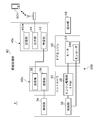
- FIG. 2 is a block diagram schematically illustrating the automatic door maintenance support system of FIG. 1.
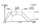
- FIG. 3 is a diagram illustrating an example of a transition of a door speed in the opening operation of the automatic door of FIG. 1.
- FIG. 2 is an explanatory diagram illustrating a method of estimating a maintenance time of the automatic door of FIG. 1.
- FIG. 2 is another explanatory diagram illustrating a method for estimating a maintenance time of the automatic door of FIG. 1.
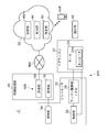
- It is a block diagram showing roughly the automatic door maintenance support system concerning a 2nd embodiment.
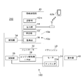
- It is a block diagram showing roughly the automatic door device concerning a 3rd embodiment.
- FIG. 8 is a flowchart showing a process of a computer program of the automatic door device of FIG. It is a front view showing roughly the automatic door to which the automatic door maintenance support system concerning a 10th embodiment was applied.
- FIG. 10 is a block diagram schematically illustrating the automatic door maintenance support system of FIG. 9.
- FIG. 10 is a diagram illustrating an example of a relationship between a stroke and a door speed of the automatic door in FIG. 9.
- FIG. 10 is a diagram illustrating another example of the relationship between the stroke and the door speed of the automatic door in FIG. 9.
- One embodiment of the present invention relates to an automatic door maintenance support system.
- This system includes an acceleration region in which the door of the automatic door is accelerated to a predetermined first speed (acceleration control state), a high-speed region in which the door is maintained at the first speed (first speed control state), A motor that drives a door in at least one of a deceleration range where the speed is reduced to a low second speed (deceleration control state) and a deceleration range where the speed is maintained at the second speed (second speed control state)
- An information acquisition unit that acquires information about the state of the motor (hereinafter, referred to as “state information”), and a specification unit that specifies information about maintenance of the automatic door by illuminating the acquired state information of the motor with a predetermined reference value. .
- the system may assist in maintaining one or more automatic doors.
- the predetermined first speed may be a relatively high speed after the door has been accelerated.
- the motor state information may be an electric numerical value of the motor, or may
- the state information of the motor described above may be acquired at a plurality of timings in at least one of the control states of the acceleration range, the high speed range, the deceleration range, and the low speed range.
- the evaluation since the evaluation is performed at a plurality of points instead of one point in the speed range, various information such as obtaining the power consumption of the motor from the motor voltages at multiple points can be obtained.
- the plurality of timings may be an intermediate timing of each speed range and a switching timing between the speed ranges.
- the motor state information in each speed range (each control state) is used. It is possible to improve the accuracy of condition diagnosis and maintenance necessity prediction. In particular, by using the state information of the motor, it is possible to configure without using a large additional device, and it is also possible to acquire the state change of the drive system and the electric system, and to isolate the portion where the condition is lowered.
- the status information can also be applied to the level evaluation of the necessity of maintenance.
- the motor status information can also be used to determine the quality of the automatic door installation, such as excessive belt tension.
- the above-described motor state information may be acquired when the control state of the acceleration range, the high speed range, the deceleration range, and the low speed range is switched. In this case, by acquiring at the time of switching, the acquisition timing becomes constant, and errors due to fluctuations in the acquisition timing can be suppressed. Further, since information is acquired at the time of switching, the amount of information is always smaller than in the case of acquiring information, and storage and processing thereof are facilitated.
- the above-mentioned reference value may be set or updated according to the motor status information acquired in the past.
- the reference value since the reference value is set based on the state information of the own motor, it is hard to be affected by individual performance differences (variation during manufacturing) of the automatic door. For example, if an initial acquisition value is used as a reference value, information can be acquired as a change from the initial value.
- by appropriately updating the reference value it is possible to eliminate the influence of variations due to environmental fluctuations such as summer and winter.
- the system described above may include a presentation unit that presents status information of the automatic door.
- a presentation unit that presents status information of the automatic door.
- the state information of the motor described above may include at least one of state information of voltage, current, rotation speed, vibration, and temperature of the motor.
- the state information of the automatic door can be specified from the state information of the voltage, current, rotation speed, vibration and temperature of the motor.
- the above-described specifying unit may classify the acquired motor state information based on a threshold value.
- the state of the motor can be accurately determined by classifying the state information by a threshold value and using the classification result.
- the threshold may be a limit above which replacement is recommended.
- Another embodiment of the present invention is an automatic door maintenance support device.
- This device includes an acceleration control state in which an automatic door is accelerated to a first speed, a first speed control state in which the door is maintained at a first speed, and a deceleration in which the speed is reduced to a second speed lower than the first speed.
- An acquisition unit that acquires state information of a motor that drives a door in at least one of a control state and a second speed control state that is held at a second speed; and acquires the acquired state information of the motor.
- an output unit for outputting For example, the automatic door maintenance support device may acquire the state information from the motor of the automatic door, and output the acquired result from the output unit to the management center.
- the management center can analyze the obtained result and specify the necessity of maintenance of the automatic door.
- the output unit may output the obtained result to a predetermined memory and store the obtained result in the memory.
- the serviceman can determine the necessity of maintenance of the automatic door from the result of storage in the memory.
- the method includes an acceleration control state in which the door of the automatic door is accelerated to a first speed, a first speed control state in which the door is maintained at the first speed, and a deceleration in which the door is reduced to a second speed lower than the first speed. Acquiring at least one of the control state and the second speed control state held at the second speed by using a sensor to obtain state information of the motor driving the door; and Identifying the information on maintenance of the automatic door by comparing the status information with a predetermined reference value.
- the accuracy of the state diagnosis of the automatic door and its components and the prediction of the necessity of the maintenance are compared with the case where the failure diagnosis is simply performed based on the number of times of opening and closing. Can be improved.
- Another aspect of the present invention is also an automatic door maintenance support method.
- the method includes an acceleration control state in which the door of the automatic door is accelerated to a first speed, a first speed control state in which the door is maintained at the first speed, and a deceleration in which the door is reduced to a second speed lower than the first speed.
- a step of monitoring the behavior of the electric numerical value of the motor driving the door based on the behavior And identifying the state information of the automatic door.
- the electric numerical value of the motor in each control state (speed range)
- the state diagnosis and maintenance of the automatic door and its components are compared with the case where the failure diagnosis is simply performed based on the number of times of opening and closing.
- the accuracy of the necessity prediction can be improved.
- the electrical value for the motor may include any of the voltage, current, rotation speed, vibration, and temperature of the motor.
- the motor status information may be an electrical numerical value corresponding to the motor status.
- the electrical value may be a motor torque, a motor power consumption, a motor drive current (hereinafter simply referred to as “current”), a motor drive voltage, or the like.
- the predetermined reference value may be a reference value set at the time of installation or maintenance of the automatic door, or may be a reference value updated and set at a predetermined time or when a predetermined event occurs. Is also good.
- the accuracy of the state diagnosis of the automatic door and its components and the prediction of the necessity of maintenance can be improved as compared with the case of performing a failure diagnosis or the like simply based on the number of times of opening and closing.
- this component includes a door roller of an automatic door, a traveling rail on which the door roller travels, a gear mechanism between a motor and a driving pulley, a driving pulley, a driven pulley, a timing belt, a guide rail that guides a lower portion of the door, around the door. Rubber packing and the like are provided.
- each part of the motor it is possible to estimate the deterioration state of each part of the motor.
- the state of deterioration of each part include deterioration of the field magnet of the motor, deterioration of the armature coil, and decrease of the lubricating oil of the rotating part.
- the above-mentioned reference value may be set according to information on the state of the motor acquired in the past (hereinafter, referred to as “past information”).
- the reference value may be set by adding a predetermined value to past information, or may be set by multiplying past information by a predetermined value.
- the predetermined value by which the past information is multiplied may be one or more values.
- This reference value may be set after maintenance work such as installation and maintenance of an automatic door (hereinafter simply referred to as “maintenance”).
- the term “after installation or maintenance” may be immediately after the installation or maintenance, or may be after a certain number of times (for example, 100 times) of opening and closing after installation or maintenance.
- the reference value may be an average value, a median value, or a specific value of the state information at the time of opening and closing a certain number of times after installation and maintenance after opening and closing.
- the specific value may be a value specified from information within a certain range among the respective pieces of state information.
- the reference value is not limited to after the installation or maintenance, but may be set at a predetermined time or when a predetermined event occurs.
- the above-mentioned reference value may be set according to information on the state of the motor acquired after opening and closing operations for a predetermined number of times.
- the reference value can be set after the hardness of a member made of a material having a large temperature characteristic such as rubber or the viscosity of grease applied to the movable portion is stabilized, so that accurate determination can be made.
- a member made of a material having a large temperature characteristic such as rubber or the viscosity of grease applied to the movable portion is stabilized, so that accurate determination can be made.
- examples of such a member include a door roller made of rubber, and examples of such grease include grease applied to a shaft or a bearing of a motor.
- the above-mentioned specifying unit may specify using a threshold.
- the threshold may be set according to at least two combinations of the weight of the door, the area of the main surface of the door, the aspect ratio of the main surface of the door, the installation environment of the door, and the type of the automatic door. In this case, the influence of the error due to the installation environment of the automatic door can be reduced.
- the identification unit may determine whether or not the deviation between the above-described reference value and the motor state information exceeds a threshold.
- the main surface of the door refers to the surface having the largest area among the respective surfaces of the door
- the type of the automatic door is set according to the capacity of the controllable motor, and other than the motor driving circuit. Are set depending on the difference in the circuit configuration.
- the above-described specifying unit may estimate the time at which maintenance should be performed based on the frequency of opening and closing the door. In this case, it is possible to predict the recommended maintenance time and the replacement time of the member.
- This opening / closing frequency may be a value obtained by evaluating the opening / closing frequency of the specific object automatic door itself for a certain period, or a value set as an estimation parameter for the specific object. You may. A value obtained by evaluating these or a set value may be stored in the storage unit as a frequency value.
- the specifying unit may estimate the time when maintenance should be performed using the stored frequency value.
- the maintenance time may be the recommended maintenance time.
- Either the threshold value, the maintenance time, or the opening / closing frequency can be set as one of the parameters. Therefore, the above-described threshold may be set based on the opening / closing frequency.
- the maintenance time may be set as a predetermined period (for example, six months or one year), and a threshold value may be set according to the predetermined period and the frequency value described above.
- the frequency of opening and closing of automatic doors of tourist facilities, leisure facilities, and the like greatly differs depending on the season, or between busy periods and non-busy periods. Also, depending on the season, it may be used while being opened or closed. For this reason, the above-mentioned opening / closing frequency may be updated at predetermined intervals. In this case, it is possible to cope with seasonal variations in the opening and closing frequency.
- the above-described frequency value may be updated with a value obtained by re-evaluating the opening / closing frequency of the target automatic door or a newly set value.
- the predetermined interval may be determined by a period during which the frequency of opening and closing of the automatic door changes, such as one month, three months, and six months.
- the above-described specifying unit may also evaluate a change in information on the state of the motor.
- a deteriorated portion can be specified to some extent.
- a fluctuation cycle can be specified by analyzing a pattern of a state fluctuation.
- a frequency analysis by Fourier transform can be used.
- the rotation cycle component of the door wheel, the rotation cycle component of the pulley, the rotation cycle component of the motor, or the non-periodic component is confirmed in the state fluctuation, it is considered that the member related to the component has deteriorated. it can.
- efficient and accurate maintenance work can be performed.
- the acquisition unit described above may acquire information on the state of the motor even in the second speed control state in which the door is held at the second speed lower than the first speed.
- the deteriorated part can be specified to some extent.
- the different speeds may be the first speed and the second speed described above.
- the acquisition unit may acquire the state information in the first speed control state held at the first speed and the state information in the second speed control state held at the second speed.
- the state information changes proportionally to the speed, it can be considered that the magnet or coil of the motor has deteriorated, and when it does not change proportionally, it can be considered that the mechanical system has deteriorated.
- the information on the state of the motor described above may be information on a current flowing through the motor.
- the state information can be easily detected without separately providing a sensor.
- the current flowing through the motor (hereinafter, referred to as “motor current”) can be detected by a current sensor provided in a path through which the current flows.
- the current sensor may be a shunt resistor connected in series with the motor.
- the motor current may be obtained from a drive voltage applied to the motor.
- the motor current may be calculated from the duty ratio of the drive voltage of the motor.
- the acquisition unit described above may acquire information on the state of the motor even in a deceleration control state in which the motor is decelerated from the first speed.
- a deceleration control state in which the motor is decelerated from the first speed.
- the state information in the deceleration control state it is possible to identify the deteriorated part to some extent. For example, when the mechanical system is deteriorated and the load is increasing, the deceleration becomes large, and when the motor is deteriorated, the deceleration becomes small. Therefore, the deteriorated portion can be specified based on the difference between them.
- a presentation unit may be provided for presenting the specified result of the above-described specified unit, and the presentation unit may be arranged near the door.
- the deterioration status can be recognized by the owner, the user, the manager, and the like of the automatic door.
- the presentation unit may be a notification device that emits light or sound, or a display device that outputs images or sound.
- the presentation unit may be provided on a blind, frame, pillar, wall, or the like of the automatic door.
- An output unit for outputting the specified result of the specified unit may be provided.
- the degradation status can be notified to a remote location.
- the output unit may output the specified result to an external device by a wired or wireless communication means, or may transmit an e-mail.
- This communication means may include a network such as the Internet.
- This communication means may output the specified result by short-range wireless communication.
- the external device may be a computer, a server, a cloud, or the like provided separately from the automatic door, or may be a mobile terminal or a smartphone possessed by a service person.
- a transmission unit that transmits the acquisition result of the acquisition unit to the cloud server may be provided.
- the acquisition unit may be provided at or near the automatic door, and the identification unit may be provided at the cloud server.
- the threshold can be easily updated.
- the state information can be analyzed by an advanced technique such as Fourier analysis.
- the transmission unit may transmit the acquisition result (state information) of the acquisition unit to the cloud server via the communication unit and the network.
- the cloud server is not particularly limited as long as it is a server provided on a cloud environment.
- This device includes an opening / closing mechanism including a door, a driving mechanism for opening and closing the door with a motor, a control unit for controlling the motor, and motor state information in a speed control state in which the door is held at a predetermined speed by the control unit. And an identification unit that illuminates the acquired state information with a predetermined reference value and identifies information related to automatic door maintenance.
- the opening / closing mechanism may include a door, a door roller that supports the door, and a rail on which the door roller runs.
- the driving mechanism includes a motor, a driving pulley driven by the motor, a driven pulley provided in a pair with the driving pulley, a belt wound around the driving pulley and the driven pulley, and a connecting portion connecting the belt and the door. It may be. According to this aspect, since acquisition and identification are performed within the range of the automatic door, connection between the acquisition unit and the identification unit is facilitated and the configuration is simplified as compared with a case where the identification unit is separately provided outside. Can be. That is, it is not necessary to separately provide a maintenance support system.
- Another aspect of the present invention is an automatic door maintenance support method.
- the method includes the steps of acquiring state information of a motor that drives the door in a speed control state in which the door of the automatic door is held at a predetermined speed, and illuminating the acquired state information with a predetermined reference value, Identifying information regarding maintenance of the door.
- the state information since the state information is used, the accuracy of the state diagnosis of the automatic door and its components and the prediction of the necessity of maintenance can be improved as compared with the case of performing a failure diagnosis or the like simply based on the number of times of opening and closing.
- Another embodiment of the present invention is a program for causing a computer to execute an automatic door maintenance support method.
- the program includes a step of acquiring state information of a motor driving the door in a speed control state in which the door of the automatic door is held at a predetermined speed, and illuminating the acquired state information with a predetermined reference value, Identifying information regarding maintenance of the door.
- the state information since the state information is used, the accuracy of the state diagnosis of the automatic door and its components and the prediction of the necessity of maintenance can be improved as compared with the case of performing a failure diagnosis or the like simply based on the number of times of opening and closing.
- FIG. 1 is a front view schematically showing an automatic door 100 to which the automatic door maintenance support system 1 according to the first embodiment is applied.
- FIG. 2 is a block diagram schematically showing the automatic door maintenance support system 1.
- Each of the functional blocks shown in FIG. 2 can be realized in terms of hardware by electronic elements such as a CPU of a computer, mechanical parts, and the like, and can be realized by software such as a computer program.
- the functional blocks realized by cooperation are drawn. Therefore, it is understood by those skilled in the art that these functional blocks can be realized in various forms by a combination of hardware and software. The same applies to functional blocks in FIGS. 6 and 7 described later.
- the automatic door maintenance support system 1 includes an automatic door 100 and an information processing unit 40.
- the automatic door 100 is driven by a motor 24 to open and close the door 12.
- the information processing section 40 processes information relating to the state of the motor 24 (hereinafter, referred to as “state information Li”). First, the automatic door 100 will be described, and the information processing unit 40 will be described later.
- the automatic door 100 includes a door engine 10, a door 12, a belt 14, a driving pulley 16, a driven pulley 18, a traveling rail 20, a suspension unit 22, a controller 30, a door sensor 32, a presentation unit 48, , A guide rail 82 and a rubber packing 84.
- the movable direction of the door 12 of this embodiment is parallel to the horizontal X-axis direction.
- the expected direction of the door 12 is parallel to a horizontal Y-axis direction orthogonal to the X-axis direction.
- the vertical direction of the door 12 is parallel to the Z-axis direction orthogonal to the X-axis direction and the Y-axis direction.
- Such notation of the direction does not limit the use posture of the automatic door 100, and the automatic door 100 can be used in any posture depending on the application.
- the presentation unit 48 will be described later.
- the door engine 10 includes a motor 24 and a gear mechanism (not shown) that drives the drive pulley 16 to rotate based on the rotation of the motor 24.
- the door engine 10 functions as a power source for opening and closing the door 12 by the driving force of the motor 24.
- the motor 24 is driven by an IPM (intelligent power module) provided in an engine drive unit 28 described later.
- the motor 24 may be a motor based on various known principles.
- the motor 24 of the present embodiment is a brushless motor having an encoder 24e using a Hall IC.
- the driven pulley 18 is provided apart from the driving pulley 16 in the X-axis direction.
- the belt 14 is looped around the outer circumference of the driving pulley 16 and the driven pulley 18.
- the belt 14 rotates the driven pulley 18 as the driving pulley 16 rotates.
- the belt 14 may be a timing belt with teeth.
- the running rail 20 is a rail member for guiding the door 12 above the door 12, and extends in the movable direction of the door 12 (X-axis direction).
- the suspension unit 22 is a mechanism for suspending the door 12 on the traveling rail 20, and is provided above the door 12.
- the suspension unit 22 has a door roller 22c that rolls on the traveling rail 20, and is supported by the traveling rail 20 via the door roller 22c.
- the door 12 is connected to the belt 14 via a connecting member 12j.
- the door sensor 32 is attached to the blind 80 or the like, and detects a pedestrian or the like.
- the controller 30 opens and closes the door 12 by controlling the motor 24 of the door engine 10 according to the detection result of a pedestrian or the like from the door sensor 32.
- the controller 30 includes an engine drive unit 28 that drives the motor 24 of the door engine 10, a control unit 26 that controls the operation of the automatic door 100, and a detection unit 34 that detects state information Li of the motor 24.
- the detection unit 34 will be described later.
- the guide rail 82 is a rail having a groove extending in the X-axis direction for guiding the steady rest 12 s extending from the lower part of the door 12.
- the rubber packing 84 is provided around the door 12 or the like mainly to improve airtightness. When the door 12 moves, the rubber packing 84 rubs against either the movable part or the fixed part.
- the automatic door 100 configured as described above, when the motor 24 drives the drive pulley 16 to rotate, the drive pulley 16 and the driven pulley 18 rotate, and the belt 14 moves in a loop.
- the suspension part 22 suspended on the belt 14 via the connecting member 12j moves on the traveling rail 20 in the X-axis direction.
- the door 12 moves in the X-axis direction together with the suspension unit 22 to perform an opening / closing operation.
- door speed Vd is proportional to the rotation speed of the motor 24.
- the automatic door 100 opens the door 12 when the door sensor 32 detects a pedestrian or the like, and closes the door 12 at a predetermined timing when the door sensor 32 stops detecting a pedestrian or the like.
- FIG. 3 is a diagram illustrating an example of a change in the door speed Vd of the door 12 during the opening operation.
- the horizontal axis represents the position from the closed position to the open position of the door 12 (hereinafter referred to as “door position”)
- the vertical axis represents the door speed Vd of the door 12 and the current for driving the motor 24 (hereinafter, referred to as “door position”).
- door position represents the position from the closed position to the open position of the door 12
- door position the current for driving the motor 24
- the opening operation of the present embodiment includes an accelerating operation for accelerating the door 12 stopped at the closed position to a predetermined first speed, a first speed control operation for maintaining the first speed, and a deceleration for decelerating to the second speed.
- This includes an operation, a second speed control operation for maintaining the second speed, and a door hitting operation for stopping the door 12 by contacting the door 12 with a stopper (not shown).
- the acceleration operation, the first speed control operation, the deceleration operation, the second speed control operation, and the door hit operation are collectively referred to as “each operation”.
- the first speed is higher than the second speed, and the second speed is lower than the first speed.
- the automatic door 100 keeps the speed Vd of the door 12 constant at the first speed. This state is called a first speed control state.
- the automatic door 100 keeps the speed Vd of the door 12 constant at the second speed. This state is called a second speed control state.
- the first speed control state and the second speed control state are collectively referred to as “each control state”.
- the operation In the acceleration operation, when the speed Vd reaches the first speed, the operation is switched to the first speed control operation.
- the first speed control operation when the door position reaches the predetermined position, the operation is switched to the deceleration operation.
- the deceleration operation when the speed reaches the second speed, the operation is switched to the second speed control operation.
- the second speed control operation the door 12 is moved to the open position. When the door 12 reaches the open position, the door 12 comes into contact with the stopper and stops by the door contact operation.
- the supply voltage to the motor 24 (hereinafter simply referred to as “motor voltage”) is controlled such that the relationship between the door position and the door speed Vd follows a predetermined acceleration curve.
- the motor voltage is pulse width modulated (PWM modulated) and is controlled by its duty ratio.
- PWM modulated pulse width modulated
- the motor 24 may be subjected to constant voltage control, constant current control, or constant acceleration control. In this operation, as shown in FIG. 3, the motor current Id increases as the door speed Vd increases.
- the motor voltage is controlled so as to suppress the fluctuation.
- the motor 24 may be controlled at a constant speed. This control may be control for feeding back the detected motor speed or control not including feedback.
- the first speed may be the maximum moving speed of the door 12 or a speed close thereto. In this operation, as shown in FIG. 3, the motor current Id is substantially constant, although there is some variation.
- the motor voltage is controlled so that the relationship between the door position and the door speed Vd follows a predetermined deceleration curve. In this operation, the motor voltage is gradually reduced, and the speed is reduced by the sliding load of the door 12 or the like.
- the brake torque may be generated by a short brake operation that short-circuits the back electromotive force of the motor 24, or the brake torque may be generated by supplying the motor 24 with a voltage having a polarity opposite to that during acceleration. .
- the motor 24 may be controlled by constant voltage control, constant current control or constant acceleration control. In this operation, as shown in FIG. 3, the motor current Id decreases as the door speed Vd decreases.
- the motor voltage is controlled so as to suppress the fluctuation.
- the motor 24 may be controlled at a constant speed.
- the door 12 that moves at the second speed is brought into contact with the stopper to stop the door 12.
- the second speed may be a speed lower than the first speed, for example, a slow speed in which the door 12 stops in a short time, in order to reduce an impact when the door 12 is brought into contact with the stopper.
- the motor current Id is substantially constant, although there is some variation.
- the door 12 comes into contact with the stopper at the open position and stops. A slight change in position of the door 12 may occur due to the recoil of the contact.
- electric power enough to maintain the door 12 at the open position may be supplied to the motor 24, or power supply to the motor 24 may be stopped. This power supply may be temporary or continuous.
- the closing operation is an operation in which the door 12 is moved from the open position to the closed position and stopped.
- the closing operation is different from the opening operation in that the moving direction of the door 12 is opposite, and, like the opening operation, the acceleration operation, the first speed control operation, the deceleration operation, the second speed control operation, and the door contact operation. And Each of these operations is similar to the opening operation, and redundant description is omitted.
- the information processing unit 40 processes the state information Li of the motor 24 to support maintenance of the automatic door 100.
- Some or all of the components of the information processing unit 40 may be provided integrally with the controller 30, may be provided separately from the controller 30, or may be provided separately from the automatic door 100. Good.
- the acquisition unit 36 and the transmission unit 38 are provided in a first block 40b integrated with the controller 30.
- the identification unit 42, the output unit 44, and the storage unit 40m are provided in a second block separate from the controller 30. 40c.
- the second block 40c is provided in a computer of a management center that manages one or a plurality of automatic doors.
- the acquisition unit 36 acquires the state information Li of the motor 24 detected by the detection unit 34.
- the acquisition unit 36 acquires the state information Li of the motor 24 that drives the door 12 in the first speed control state and the second speed control state.
- the state information Li of the present embodiment is the motor current Id.
- the acquisition unit 36 of the present embodiment acquires the state information Li from the detection result of the detection unit 34.
- the detection unit 34 can detect the motor current Id as a voltage drop of a shunt resistor (not shown) connected in series to the motor 24.
- the acquisition unit 36 can acquire the door speed Vd according to the cycle and frequency of the output signal of the encoder 24e of the motor 24.
- the acquisition unit 36 can acquire the door position of the door 12 by counting the output signal of the encoder 24e.
- the transmission unit 38 transmits the acquisition result of the acquisition unit 36 to the identification unit 42 via a network or a data bus.
- the acquisition result of the acquisition unit 36 is also the state information Li.
- the identification unit 42 illuminates the state information Li acquired by the acquisition unit 36 with a predetermined reference value Ls, and identifies information on maintenance of the automatic door 100.
- the specifying unit 42 specifies the information on the maintenance of the automatic door 100 by illuminating the state information Li with the reference value Ls.
- the reference value Ls of the present embodiment is a reference value set when the automatic door 100 is installed or when the automatic door 100 is maintained.
- the specifying unit 42 determines that maintenance is necessary when the deviation of the state information Li from the reference value Ls is large, and determines that maintenance is unnecessary when the deviation is small.
- the specifying unit 42 may determine that maintenance is required within a certain period when the deviation is medium.
- the output unit 44 outputs the specified result Sj of the specified unit 42 to the outside.
- the output unit 44 outputs the identification result Sj of the identification unit 42 to the presentation unit 48.
- the presentation unit 48 presents the specified result Sj.
- the presenting unit 48 of the present embodiment is arranged in a frame near the door 12, and has an LED 48b.
- the presentation unit 48 presents the specific result based on the lighting state of the LED 48b. In this example, the LED 48b is illuminated in green when maintenance is not required, the LED 48b is illuminated in yellow when maintenance is required within a certain period, and the LED 48b is illuminated in red when maintenance is required early.
- the output unit 44 outputs the specified result Sj to the information terminal 60h via the communication unit.
- the output unit 44 may transmit the specified result Sj as an e-mail to the information terminal 60h.
- the information terminal 60h may be a desktop type or may be portable by a service person. By displaying the identification result Sj on the information terminal 60h carried by the service person, it is possible to easily grasp the abnormality of the automatic door 100 and the necessity of maintenance. In this case, the abnormality of the automatic door and the necessity of maintenance can be easily explained to the owner of the automatic door.
- the storage unit 40m stores a reference value Ls, state information Li, a specified result Sj, a threshold Lt, and an opening / closing frequency F, which will be described later.
- the reference value Ls will be described.
- the reference value Ls may be set to a value calculated on design.
- the reference value Ls may be set to an average value of the state information of the motors of a plurality of other automatic doors of the same type.
- the reference value Ls is set according to the state information Li of the motor 24 itself acquired in the past.
- the reference value Ls is set in the state information of the motor 24 itself acquired at the time of installing the automatic door 100 or at the time of maintenance.
- the state information used for the reference value Ls may be acquired immediately after the installation and maintenance of the automatic door 100, but in this example, the opening / closing operation is performed a predetermined number of times (for example, 100 times) from the installation and maintenance of the automatic door 100. This is the state information obtained after the operation.
- the reference value Ls may be set in the state information at the time of one opening / closing operation, but in this example, the reference value Ls is an average value of a plurality of state information at the time of performing the opening / closing operation a plurality of times.
- the reference value Ls may be constant until the next maintenance. However, the state of the motor has a temperature characteristic, and may increase when the air temperature is low and decrease when the air temperature is high. Therefore, the reference value Ls may be updated every predetermined season.
- the set or updated reference value Ls is stored in the storage unit 40m.
- the specifying unit 42 of the present embodiment classifies the deviation of the state information Li from the reference value Ls using one or a plurality of thresholds Lt, and sets the classification result as the specification result Sj.
- the specifying unit 42 is configured to perform a notification prompting maintenance (hereinafter, referred to as “maintenance notification”).
- the threshold value Lt may be set to a value calculated on design.
- the speed of wear and deterioration of the components of the automatic door differs depending on the weight of the door, the magnitude of the wind pressure applied to the door, and the like.
- the threshold Lt is determined by the weight of the door 12, the area of the main surface of the door 12, the aspect ratio of the main surface of the door 12, the installation environment of the door 12 (such as a salt damage area), and the type of the automatic door 100. Can be set according to a combination of at least two of.
- the threshold Lt is set based on factors selected from these in accordance with the situation of the installation site of the automatic door 100.
- the threshold value Lt may be constant once set, but the rate of wear and deterioration may change due to various factors. For this reason, the threshold Lt may be updated in accordance with a change state of the factor.
- the set or updated threshold value Lt is stored in the storage unit 40m.
- FIGS. 4 and 5 are explanatory diagrams illustrating a method of estimating the maintenance time.
- the horizontal axis indicates elapsed time, and the vertical axis indicates state information.
- Lines indicated by reference signs A and B are prediction lines of the state information change with respect to the elapsed time.
- A1 and B1 are timings when the state information Li is detected, and are referred to herein as “detection timings”.
- A2 and B2 are timings at which the predicted lines A and B exceed the threshold Lt, and are timings at which maintenance notification is performed (hereinafter, referred to as "notification timing").
- A3 and B4 are timings at which the prediction lines A and B reach the limit value Lg, and are referred to herein as "limit times".
- the limit value Lg is a value which is assumed to have a high possibility of causing a failure when it reaches this value.
- $ P1 and P2 indicate the period from the notification time to the limit time (hereinafter referred to as "remaining period P").
- FIG. 4 shows a case where the threshold Lt is the same for the prediction lines A and B, and the remaining period P1 is shorter than the remaining period P2.
- FIG. 5 shows a case where the threshold Lt is different between the prediction lines A and B, and the remaining period P1 is equal to the remaining period P2.
- the inclination of the prediction lines A and B differs depending on the speed of wear and deterioration of the components of the automatic door (hereinafter referred to as “deterioration speed D”).
- the deterioration speed D is considered to be substantially proportional to the opening / closing frequency F of the door 12, and can be replaced with the product of the proportionality constant k and the opening / closing frequency F.
- the prediction line A has a higher opening / closing frequency F and a higher degradation speed D than the prediction line B, and thus has a shorter remaining period. From these, the remaining period P can be obtained from the limit value Lg, the threshold value Lt, and the deterioration speed D as shown in Expression 1.
- Remaining period P (limit value Lg ⁇ threshold value Lt) / deterioration speed D (Equation 1)
- Remaining period P (limit value Lg ⁇ threshold value Lt) / (k ⁇ opening / closing frequency F) (formula 2) From Equation 2, the remaining period P can be set according to the opening / closing frequency F.
- the threshold Lt is set based on the opening / closing frequency F so that the maintenance notification is performed when the remaining period P reaches a certain period. This fixed period may be, for example, 3 months, 6 months, 12 months, or the like.
- FIG. 5 shows a case where the threshold value Lt is changed according to the opening / closing frequency F.
- the threshold Lt is lower in the predicted line A having the higher opening / closing frequency F than in the predicted line B having the lower opening / closing frequency F.
- the remaining period P1 is substantially equal to the remaining period P2.
- the threshold Lt for keeping the remaining period P constant can be obtained from the limit value Lg, the remaining period P, and the deterioration speed D as shown in Expression 3.
- Threshold value Lt limit value Lg ⁇ remaining period P ⁇ deterioration speed D ⁇
- Threshold Lt limit value Lg ⁇ remaining period P ⁇ (k ⁇ opening / closing frequency F) (Equation 4) From Expression 4, the threshold Lt can be set according to the opening / closing frequency F.
- the opening / closing frequency F to be substituted into the above formulas 2 and 4 is initially set as one of the parameters.
- the opening / closing frequency F may be constant as it is initially set. However, the opening / closing frequency F may vary greatly depending on the season, or between a busy period and a non-busy period. Therefore, the opening / closing frequency F of the present embodiment is updated at predetermined intervals.
- the update interval of the opening / closing frequency F is set according to a period in which the opening / closing frequency of the automatic door changes, such as one month, three months, six months, or the like.
- the set or updated opening / closing frequency F is stored in the storage unit 40m.
- the identification unit 42 of the present embodiment also evaluates the fluctuation of the state information Li of the motor 24.
- a rotation cycle component of the door pulley 22c, a rotation cycle component of the drive pulleys 16 and 18, a rotation cycle component of the motor 24, and the like are extracted by frequency-analyzing the fluctuation of the state information Li. If these rotation cycle components are detected remarkably, it can be specified that the members related to the rotation cycle have deteriorated.
- This frequency analysis can be realized by performing a Fourier transform on the state information Li stored in the storage unit 40m in time series. If the non-periodic component is remarkably detected, deterioration of the traveling rail 20, the belt 14, the steady rest 12s, the guide rail 82, the rubber packing 84, and the like may be considered.
- the acquisition unit 36 of the present embodiment acquires the state information Li of the motor 24 even in the second speed control state in which the door 12 is maintained at the second speed lower than the first speed.
- the state information Li of the first and second speeds changes in proportion to the speed Vd of the door 12
- the magnet (not shown) or the coil (not shown) of the motor 24 has deteriorated, and the change in proportion to the change. If not, it can be specified that the mechanical system has deteriorated.
- the acquisition unit 36 of the present embodiment acquires the state information Li of the motor 24 even in the deceleration control state in which the motor 24 is decelerated from the first speed.
- the deceleration is large, it can be specified that the mechanical system has deteriorated, and when the deceleration is small, it can be specified that the magnets and coils of the motor 24 have been deteriorated.
- the opening operation or the closing operation is performed at a predetermined timing on a daily basis, the state information Li of the motor 24 is obtained, and the obtained state information Li is lit against the reference value Ls. Then, information on maintenance of the automatic door 100 is specified. This operation may be performed as a regular operation, for example, when the automatic door 100 starts or closes.
- the specified result Sj is presented to the presentation unit 48 and the information terminal 60h. A serviceman, an administrator, or the like may create a maintenance plan by confirming the necessity of maintenance according to the specified result Sj.
- state information Li and the specific result Sj may be stored in chronological order.
- Features such as the deterioration speed of the automatic door 100 can be specified from the state information Li stored in chronological order. The above is the description of the first embodiment.
- FIG. 6 is a block diagram schematically showing the automatic door maintenance support system 2, and corresponds to FIG.
- the same or equivalent components and members as those of the first embodiment are denoted by the same reference numerals.
- the description overlapping with the first embodiment will be omitted as appropriate, and the configuration different from the first embodiment will be mainly described.
- the acquisition unit 36 and the transmission unit 38 are provided at or near the automatic door 100, and the identification unit 42, the output unit 44, and the storage unit 40m are provided in the cloud server 50.
- the transmission unit 38 of the present embodiment transmits the result of acquisition (state information Li) of the acquisition unit 36 to the cloud server 50 via the network NW.
- the output unit 44 of the present embodiment outputs the specified result Sj of the specified unit 42 to the information terminal 60h via the network NW.
- the second embodiment differs from the first embodiment in these points, and other configurations are the same.
- the second embodiment configured as described above operates in the same manner as the first embodiment, and has the same operation and effect as the first embodiment.
- FIG. 7 is a block diagram schematically showing the automatic door device 200, and corresponds to FIG.
- the same or equivalent components and members as those of the first embodiment are denoted by the same reference numerals.
- the description overlapping with the first embodiment will be omitted as appropriate, and the configuration different from the first embodiment will be mainly described.
- the acquisition unit 36, the identification unit 42, the output unit 44, and the storage unit 40m are provided at or near the automatic door 100. These may be provided integrally with the controller 30.
- the functions of the acquiring unit 36 and the specifying unit 42 are realized by a computer 40e in hardware, and are realized by a program 40p of the computer 40e in software.
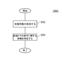
- FIG. 8 is a flowchart showing the processing S80 of the program 40p.
- the processing S80 of the program 40p includes a step S82 in which the door 12 of the automatic door 100 acquires the state information Li of the motor 24 driving the door 12 in the first speed control state, and the acquired state information Li is set to the reference value Ls.
- step S84 of identifying information relating to maintenance of the automatic door 100 The operations of steps S82 and S84 are the same as the operations of the acquisition unit 36 and the identification unit 42 described above, and redundant description will be omitted.
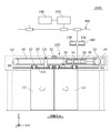
- FIG. 9 is a front view schematically showing an automatic door 100 to which the automatic door maintenance support system 1000 according to the third embodiment is applied.
- FIG. 10 is a block diagram schematically showing the automatic door maintenance support system 1.
- the automatic door maintenance support system 1000 includes a maintenance support device 140, a specifying unit 150, instead of the information processing unit 40 of the automatic door maintenance support system 1 of FIGS. And a presentation unit 160.
- the automatic door 100 is driven by a motor 24 to open and close the door 12.
- Other configurations of the information processing unit 40 of the automatic door maintenance support system 1000 are the same as those of the automatic door maintenance support system 1.
- the maintenance support device 140 acquires status information of the motor 24 to support maintenance of the automatic door 100.
- the maintenance support device 140 may be provided integrally with the controller 30, may be provided separately from the controller 30, or may be provided separately from the automatic door 100.
- the maintenance support device 140 according to the present embodiment includes an acquisition unit 136 that acquires the state information Mi of the motor 24, an output unit 138 that outputs the acquired state information Mi of the motor 24, and an acquired state information Mi of the motor 24. And a storage unit 140m for storing
- the state information Mi of the motor 24 may include at least one of a supply voltage (voltage Em), a driving current, a rotation speed, a rotation position, a vibration, and a temperature of the motor 24.
- the acquisition unit 136 of the present embodiment acquires the state information Mi from the detection result of the detection unit 134.
- the detection unit 134 of the present embodiment includes a voltage sensor 134a for detecting a supply voltage of the motor 24, a current sensor 134b for detecting a drive current of the motor 24, a speed sensor 134c for detecting the speed of the motor 24, It includes a vibration sensor 134d for detecting vibration and a temperature sensor 134e for detecting the temperature of the motor 24.
- the acquisition unit 136 of the present embodiment includes a voltage acquisition unit 136a that acquires the detection result of the voltage sensor 134a, a current acquisition unit 136b that acquires the detection result of the current sensor 134b, and a speed acquisition that acquires the detection result of the speed sensor 134c.
- Voltage sensor 134a detects voltage Em of motor 24 from its duty ratio.
- the current sensor 134b detects the drive current of the motor 24 as a voltage drop of a resistor (not shown, sometimes referred to as a shunt resistor) connected in series to the motor 24.
- the speed sensor 134c acquires the speed Vm (rotation speed) of the motor 24 according to the cycle and frequency of the output signal of the encoder (Hall IC) mounted on the motor 24. Since the door speed Vd is proportional to the speed Vm of the motor 24, it can be said that the speed sensor 134c detects the door speed Vd. Further, the rotational position of the motor 24 can be obtained by counting output signals of the encoder. In this case, the rotational position of the motor 24 over a plurality of rotations can also be detected.
- the door position (stroke value Sd) corresponds to the rotational position of the motor 24 and can be obtained by counting the output signal of the encoder.
- the temperature sensor 134e may be a sensor built in the IPM that drives the motor 24.
- the IPM may include a motor protection function such as overheat protection, short-circuit protection, overcurrent protection, and control power supply abnormality protection.
- the state information Mi may always be obtained. However, in this case, the amount of information to be obtained increases, and the capacity of the storage unit 140m required to store the information increases, which is disadvantageous in terms of size and cost. . Therefore, in the present embodiment, the state information Mi is obtained at a predetermined timing in each speed range. By doing so, the information amount of Mi can be reduced, and the capacity of the storage unit 140m can be suppressed.
- the state information Mi may be acquired at a plurality of timings.
- the state information Mi may be acquired at the timing corresponding to the intermediate position of the predetermined stroke value Sd and the end timing of each speed range.
- the diagnosis is performed based on the information of a plurality of timings, it is possible to improve the accuracy of diagnosing the presence or absence of an abnormality and the necessity of maintenance.
- the state information Mi in the speed range is evaluated not at one point but at multiple points, it is possible to obtain various information on the motor 24, such as calculating power consumption from voltages at multiple points.
- the maintenance support device 140 of the present embodiment acquires the state information Mi at the end timing of each speed range.
- the end of the speed range may be at the time of switching between a plurality of speed ranges.
- the maintenance support device 140 may acquire the state information Mi for each opening operation, may acquire it at a predetermined event, or may acquire it at a predetermined time.
- the state information Mi is acquired at the time of starting inspection of the automatic door 100.
- the state information Mi may be acquired when the automatic door which has been in the non-operation state is switched to the movable state and the test operation is performed several times. In this case, it is possible to reduce the influence of the temperature difference of the motor or the like due to the difference in the operation status immediately before.
- the state information Mi may be acquired at regular time during a time period when the operation rate is low, such as early in the morning.
- the acquisition operation of the state information Mi may be incorporated in the control sequence of the start-up inspection, and this acquisition operation may be automatically executed at the start-up inspection.
- the maintenance support device 140 stores the acquired state information Mi in the storage unit 140m.
- the maintenance support device 140 outputs the stored state information Mi to the specifying unit 150 described below via the communication unit.
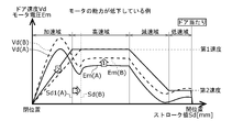
- FIG. 11 is a graph showing the door speed Vd and the voltage Em with respect to the movement stroke Sd (hereinafter, referred to as “stroke value Sd”) from the closed position to the open position of the door 12 in the opening operation.
- the solid line in this figure shows the door speed Vd (A) and the voltage Em (A) of the automatic door 100 (A) in the initial state where the motor 24 has not deteriorated.
- the broken lines in this figure indicate the door speed Vd (B) and the voltage Em (B) of the automatic door 100 (B) in a state where the performance of the motor 24 is reduced.
- the following diagnosis can be made from the graph of stroke versus speed / voltage in FIG. (1) Since the capacity of the motor 24 is low in the automatic door 100 (B), the voltage Em (B) of the automatic door 100 (B) in the high-speed range is higher than the voltage Em (A) of the automatic door 100 (A). (2) Since the capacity of the motor 24 is low in the automatic door 100 (B), the door speed Vd (B) of the automatic door 100 (B) corresponding to the same stroke value Sd in the acceleration range is the automatic door 100 (A). Is lower than the door speed Vd (A).
- a deterioration state (deterioration state) of the performance of the motor 24 according to the state information Mi of the motor 24 such as the door speed Vd and the voltage Em in each speed range.
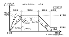
- FIG. 5 is a graph showing the door speed Vd and the voltage Em with respect to the stroke value Sd of the door 12 in the opening operation.
- the solid line in this figure shows the door speed Vd (A) and the voltage Em (A) of the automatic door 100 (A) in an initial state where the door wheel 22c is not worn.
- the broken lines in this figure show the door speed Vd (C) and the voltage Em (C) of the automatic door 100 (C) in a state where the door wheel 22c is worn.
- the following diagnosis can be made from the graph of stroke vs. speed / voltage in FIG. (1) Since the running resistance is high in the automatic door 100 (C), the voltage Em (C) of the automatic door 100 (C) in the acceleration region and the high speed region is higher than the voltage Em (A) of the automatic door 100 (A). . (2) Since the running resistance is high in the automatic door 100 (C), the door speed Vd (C) of the automatic door 100 (C) corresponding to the same stroke value Sd in the acceleration region is equal to the door speed of the automatic door 100 (A). The speed is lower than Vd (A).
- the present embodiment it is possible to diagnose an increase in running resistance due to abrasion of the door roller 22c or the like according to the state information Mi of the motor 24 such as the door speed Vd and the voltage Em in each speed range.
- FIG. 11 and FIG. 12 are compared, there is a difference in the voltage Em in the deceleration region as shown by the arrow 4 in FIG. That is, when the performance of the motor 24 is reduced, the voltage Em (B) is significantly higher than the voltage Em (A) even in the deceleration range.
- the running resistance is high, the vehicle is also decelerated by the running resistance, so that the voltage Em (C) can be smaller than the voltage Em (B) under the constant deceleration condition. Therefore, in the present embodiment, it is possible to determine which component condition is being reduced according to the magnitude of the voltage Em in the deceleration range.
- the specifying unit 150 may be provided integrally with the controller 30 or the maintenance support device 140, may be provided separately from the controller 30 or the maintenance support device 140, or may be provided separately from the automatic door 100. Is also good.
- the specifying unit 150 may be connected to the controller 30 or the maintenance support device 140 via a data bus, or may be connected via a communication network. This data bus or network may be wired or wireless.
- the communication network may be a public line or a dedicated line.
- the specifying unit 150 of the present embodiment is provided in a computer installed in a management center and connected to the maintenance support device 140 via a communication network NW. In this case, one computer can support maintenance of a plurality of automatic doors.
- the communication network NW may include the Internet.
- the identification unit 150 identifies the state information Di of the automatic door 100 according to the state information Mi of the motor 24 in order to support maintenance of the automatic door 100.
- the status information Di of the automatic door 100 is information on the status of the automatic door 100, and may be, for example, information on maintenance of the automatic door 100.
- the state information Di of the automatic door 100 is information on the necessity of maintenance such as necessity of maintenance and timing of maintenance.
- the specifying unit 150 of the present embodiment specifies the automatic door state information Di by illuminating the motor state information Mi acquired by the acquiring unit 136 with a predetermined reference value Si. In this case, the state information Di of the automatic door 100 can be specified with higher accuracy than in the case where the diagnosis is simply made based on the number of times of opening and closing.
- the identification unit 150 includes a second storage unit 152 and a calculation unit 154.
- the second storage unit 152 stores the reference value Si, the acquired state information Mi of the motor 24, and the identified state information Di of the automatic door 100.
- the calculation unit 154 specifies the state information Di of the automatic door 100 according to the reference value Si and the state information Mi of the motor 24.
- the reference value Si may be set according to motor status information of another automatic door having the same configuration as the automatic door 100.
- the reference value Si of the present embodiment is set for the automatic door 100 itself according to the state information Mi of the motor 24 acquired in the past. In this case, it is possible to reduce the influence of errors caused by manufacturing variations of the automatic door, variations in settings at the time of installation, and the like, so that the accuracy of specifying the state information Di of the automatic door 100 can be improved.
- the reference value Si may be set based on the state information Mi acquired when the door 12 is opened a predetermined number of times (for example, 100 times or 1000 times) after the automatic door 100 is installed. In this case, since the operation such as the adjustment operation or the break-in operation is performed, it is less likely to be affected by mechanical adaptation in the initial stage.
- the reference value Si of the present embodiment is set based on the state information Mi acquired during the 100th to 300th opening operations from the installation. In this case, since the reference value Si is set at the time of operation confirmation after installation, the reference value Si after setting can also be confirmed at this time.
- the reference value Si may be set by an operation of the installer or may be set automatically.
- the setting at the initial stage of the installation may be referred to as the initial setting of the reference value Si.
- the state information Mi of the motor 24 may have temperature characteristics, and may fluctuate depending on seasons such as summer and winter. Fluctuations in the state information Mi may also occur when parts or mechanisms are replaced for maintenance or when the voltage of the commercial power supply fluctuates. It is conceivable to increase the margin at the time of diagnosis in consideration of such fluctuation, but in this case, there is a possibility that the accuracy of diagnosis is reduced. Therefore, the reference value Si of the present embodiment is updated for the automatic door 100 according to the state information Mi of the motor 24 acquired in the past. Note that such an update may be referred to as an update of the reference value Si.
- the reference value Si of the present embodiment is updated according to a calendar such as a change of a season. Further, the reference value Si of the present embodiment is updated based on the state information Mi of the 100th to 300th times from the maintenance.
- the update of the reference value Si may be automatically performed, may be performed by an operator, or may be performed by an external instruction such as a management center.
- the calculation unit 154 may calculate a difference (hereinafter, referred to as “deviation”) between the acquired state information Mi of the motor 24 and the reference value Si stored in the second storage unit 152.
- the calculation unit 154 may calculate a ratio of the deviation to the reference value Si (hereinafter, referred to as “deviation ratio”).
- the specifying unit 150 may use the deviation rate as the state information Di.
- the calculation unit 154 may classify the deviation rate based on one or more threshold values.
- the necessity of maintenance of the automatic door 100 can be accurately diagnosed by using the classification result of the deviation.
- the first threshold may be set to 10%
- the second threshold may be set to 20%
- the third threshold may be set to 30%.
- the deviation rate is 10% or less, rank 1; if the deviation rate is more than 10% and 20% or less, rank 2; if the deviation rate is more than 20% and 30% or less, rank 3, and if the deviation rate exceeds 30%, It may be classified as rank 4.
- the specifying unit 150 may use the rank as the classification result as the state information Di.
- the degree of necessity of maintenance of the automatic door 100 may be set in advance according to the classification result.
- the following shows an example of the degree of necessity of maintenance.
- Rank 1 There is no need to replace parts.
- Rank 2 Although the necessity of component replacement is low for the time being, attention is required.
- Rank 3 Parts need to be replaced, and replacement within a predetermined period (for example, within six months) is recommended.
- Rank 4 The need for parts replacement is high, and prompt replacement is recommended.
- the specifying unit 150 stores the specified result specified by the calculating unit 154 in the second storage unit 152.
- the stored specific result may include at least one of a deviation rate, a classification result, and a degree of necessity of maintenance.
- the presenting unit 160 presents the state information Di of the automatic door specified by the specifying unit 150.
- Presenting the state information Di may include at least one of displaying the state information Di, printing the state information Di, and transmitting the state information Di via the communication network NW.
- the presentation unit 160 of the present embodiment includes a liquid crystal display 160m that displays the state information Di, and a portable display 160h that can display the state information Di.
- the state information Di may be transmitted to the liquid crystal display 160m from the specifying unit 150 by wire or wirelessly.
- the portable display 160h may be carried by a service person.
- the status information Di may be transmitted from the identification unit 150 to the portable display 160h via the communication network NW.
- the operator can easily grasp the necessity of maintenance for each automatic door 100.
- the necessity of maintenance of the automatic door 100 can be easily grasped.
- the service person can promptly present the state information Di to the customer, so that time loss can be reduced and timely information can be provided. Further, by printing the state information Di by the printer 160p, explanation to the customer is simplified.
- the specifying unit 42 may provide maintenance information in which status information is classified using a plurality of thresholds.
- the present invention is not limited to this.
- a torque sensor capable of detecting the torque of the motor 24 may be separately provided, and the state information Li may be a detection result of the torque sensor.
- the motor current Id is detected using a shunt resistor
- the present invention is not limited to this.
- the motor current Id may be detected using the duty ratio of the motor voltage.
- the door speed Vd includes the acceleration control state, the first speed control state, the deceleration control state, and the second speed control state has been described, but the present invention is not limited to this.
- the door speed Vd may not include one or both of the deceleration control state and the second speed control state.
- the door 12 may be configured to stop by contacting the stopper in the first speed control state.
- the present invention is not limited to this.
- the door 12 only needs to open and close a predetermined opening, and for example, may rotate in a predetermined direction.
- the door 12 may be driven by known driving means such as a chain and a sprocket, a wire and a pulley, a rack and a pinion, and a ball and a screw nut.
- driving means such as a chain and a sprocket, a wire and a pulley, a rack and a pinion, and a ball and a screw nut.
- the door speed Vd includes an acceleration range, a high speed range, a deceleration range, and a low speed range, but the present invention is not limited to this.
- the door speed Vd may not include one or both of the deceleration range and the low speed range.
- the door 12 may be configured to abut on the stopper and stop at a high speed range.
- the detection unit 134 includes the voltage sensor 134a, the current sensor 134b, the speed sensor 134c, the vibration sensor 134d, and the temperature sensor 134e has been described. Not limited. The detection unit 134 does not need to include some of them. In addition, the detection unit 134 may include another type of sensor instead of all of them.
- the acquisition unit 136 includes the voltage acquisition unit 136a, the current acquisition unit 136b, the speed acquisition unit 136c, the vibration acquisition unit 136d, and the temperature acquisition unit 136e has been described.
- the present invention is not limited to this.
- the acquisition unit 136 may not include some of them. Further, the acquisition unit 136 may include another type of acquisition unit instead of all of them.
- the present invention relates to an automatic door maintenance support system, an automatic door maintenance support device, an automatic door device, an automatic door maintenance support method, and a program.
Landscapes
- Physics & Mathematics (AREA)
- General Physics & Mathematics (AREA)
- Engineering & Computer Science (AREA)
- Automation & Control Theory (AREA)
- Power-Operated Mechanisms For Wings (AREA)
Abstract
La présente invention concerne un système d'aide à la maintenance de porte automatique 1 qui comprend une unité d'acquisition 36 qui acquiert des informations d'état pour un moteur 24 pour entraîner une porte dans un premier état de commande de vitesse dans lequel un panneau de porte d'une porte automatique 100 est maintenu à une première vitesse désignée, et une unité d'identification 42 qui compare les informations d'état acquises à une valeur de référence prescrite et identifie des informations concernant la maintenance de la porte automatique 100. Un procédé d'aide à la maintenance de porte automatique comprend une étape d'acquisition des informations d'état pour le moteur pour entraîner la porte dans un état de commande de vitesse dans lequel le panneau de porte de la porte automatique est maintenu à une vitesse désignée, et une étape de comparaison des informations d'état acquises à une valeur de référence prédéfinie et d'identification des informations relatives à la maintenance de la porte automatique 100.
Priority Applications (4)
| Application Number | Priority Date | Filing Date | Title |
|---|---|---|---|
| CA3104046A CA3104046C (fr) | 2018-08-09 | 2019-08-01 | Systeme et methode pour la gestion d'entretien de porte automatique |
| CN201980039684.7A CN112334629A (zh) | 2018-08-09 | 2019-08-01 | 自动门保养辅助系统、自动门保养辅助装置、自动门装置、自动门保养辅助方法、程序 |
| CN202610071202.8A CN121827652A (zh) | 2018-08-09 | 2019-08-01 | 自动门保养辅助系统、自动门装置、自动门保养辅助方法以及存储介质 |
| US17/123,864 US20210102999A1 (en) | 2018-08-09 | 2020-12-16 | Automatic door maintenance support system, automatic door maintenance support apparatus, automatic door apparatus, automatic door maintenance support method, and program |
Applications Claiming Priority (4)
| Application Number | Priority Date | Filing Date | Title |
|---|---|---|---|
| JP2018-150827 | 2018-08-09 | ||
| JP2018150827A JP7304685B2 (ja) | 2018-08-09 | 2018-08-09 | 自動ドア保守支援システム、自動ドア保守支援装置、自動ドア保守支援方法 |
| JP2018222679A JP7323282B2 (ja) | 2018-11-28 | 2018-11-28 | 自動ドア保守支援システム、自動ドア装置、自動ドア保守支援方法、プログラム |
| JP2018-222679 | 2018-11-28 |
Related Child Applications (1)
| Application Number | Title | Priority Date | Filing Date |
|---|---|---|---|
| US17/123,864 Continuation US20210102999A1 (en) | 2018-08-09 | 2020-12-16 | Automatic door maintenance support system, automatic door maintenance support apparatus, automatic door apparatus, automatic door maintenance support method, and program |
Publications (1)
| Publication Number | Publication Date |
|---|---|
| WO2020031833A1 true WO2020031833A1 (fr) | 2020-02-13 |
Family
ID=69414239
Family Applications (1)
| Application Number | Title | Priority Date | Filing Date |
|---|---|---|---|
| PCT/JP2019/030181 Ceased WO2020031833A1 (fr) | 2018-08-09 | 2019-08-01 | Système d'aide à la maintenance de porte automatique, dispositif d'aide à la maintenance de porte automatique, dispositif de porte automatique, procédé d'aide à la maintenance de porte automatique et programme |
Country Status (4)
| Country | Link |
|---|---|
| US (1) | US20210102999A1 (fr) |
| CN (2) | CN121827652A (fr) |
| CA (1) | CA3104046C (fr) |
| WO (1) | WO2020031833A1 (fr) |
Cited By (4)
| Publication number | Priority date | Publication date | Assignee | Title |
|---|---|---|---|---|
| US20220356746A1 (en) * | 2021-05-10 | 2022-11-10 | GM Global Technology Operations LLC | Vehicle closure cinching control systems and methods |
| WO2023202941A1 (fr) * | 2022-04-19 | 2023-10-26 | Assa Abloy Ab | Entretien prédictif de porte |
| WO2024219315A1 (fr) * | 2023-04-19 | 2024-10-24 | ナブテスコ株式会社 | Dispositif d'entraînement de porte, procédé de commande pour dispositif d'entraînement de porte et programme de commande pour dispositif d'entraînement de porte |
| WO2024228367A1 (fr) * | 2023-05-01 | 2024-11-07 | ナブテスコ株式会社 | Appareil d'entraînement de porte, procédé de commande pour appareil d'entraînement de porte et programme de commande pour appareil d'entraînement de porte |
Families Citing this family (8)
| Publication number | Priority date | Publication date | Assignee | Title |
|---|---|---|---|---|
| US11168507B2 (en) * | 2018-08-29 | 2021-11-09 | Technology Construction, Inc. | Kinematic control system for an automatic sliding panel |
| CN111425104A (zh) * | 2020-04-09 | 2020-07-17 | 智慧式有限公司 | 一种固定轨道滑动式新型物联网自动开关门窗装置 |
| JP7400691B2 (ja) | 2020-10-23 | 2023-12-19 | トヨタ自動車株式会社 | 車両部品の寿命予測装置 |
| JP7671591B2 (ja) * | 2021-02-02 | 2025-05-02 | ナブテスコ株式会社 | 引戸位置調整支援装置及び引戸位置調整支援システム |
| CN114382360B (zh) * | 2021-11-29 | 2022-08-26 | 北京中航弱电系统工程有限公司 | 一种门磁感应控制系统 |
| CN218176984U (zh) * | 2022-08-18 | 2022-12-30 | 广东欧派克家居智能科技有限公司 | 一种同步反向联动门安装机构 |
| US12227389B2 (en) * | 2023-07-18 | 2025-02-18 | G.A.L. Manufacturing Company, Llc | Telescopic linear operator |
| WO2026057645A1 (fr) * | 2024-09-12 | 2026-03-19 | Assa Abloy Entrance Systems Ab | Commande de porte coulissante basée sur une courbe de référence de vitesse de porte à secousses limitées |
Citations (4)
| Publication number | Priority date | Publication date | Assignee | Title |
|---|---|---|---|---|
| JPH09100678A (ja) * | 1995-10-06 | 1997-04-15 | Japan Servo Co Ltd | 自動ドアの開閉制御方法 |
| JP2002218083A (ja) * | 2001-01-18 | 2002-08-02 | Hitachi Building Systems Co Ltd | 自動ドアの遠隔監視装置 |
| JP2005307613A (ja) * | 2004-04-22 | 2005-11-04 | Bunka Shutter Co Ltd | 開閉装置 |
| JP2007262653A (ja) * | 2006-03-27 | 2007-10-11 | Nabtesco Corp | 開閉装置 |
Family Cites Families (10)
| Publication number | Priority date | Publication date | Assignee | Title |
|---|---|---|---|---|
| US5587565A (en) * | 1994-04-14 | 1996-12-24 | Otis Elevator Company | Method for controlling elevator doors |
| JP3547977B2 (ja) * | 1998-02-27 | 2004-07-28 | 株式会社ナブコ | 自動ドアシステムのリモート監視装置 |
| US7181369B2 (en) * | 2001-06-15 | 2007-02-20 | Nabco, Ltd. | Method and system for administering automatic door apparatus, and automatic door apparatus |
| JP2012137386A (ja) * | 2010-12-27 | 2012-07-19 | Toshiba Mitsubishi-Electric Industrial System Corp | 電動機の予防保全装置 |
| ES2720737T3 (es) * | 2013-05-17 | 2019-07-24 | Kone Corp | Disposición y procedimiento de vigilancia del estado de una puerta automática |
| US20150059989A1 (en) * | 2013-08-27 | 2015-03-05 | Herman Gutierrez | Overhead door spring alert safety system |
| CN205419373U (zh) * | 2016-03-17 | 2016-08-03 | 舟山市南炜通力电梯工程有限公司 | 一种可以监测运行状态的电梯门机装置 |
| US11373286B2 (en) * | 2016-11-07 | 2022-06-28 | Nabtesco Corporation | Status checking device for built-in object, operation checking device and method for checking built-in object |
| CN107026778A (zh) * | 2017-03-29 | 2017-08-08 | 南京赛百联人防科技有限公司 | 基于can总线协议的防护门检测系统、检测方法及信息传输方法 |
| US11168507B2 (en) * | 2018-08-29 | 2021-11-09 | Technology Construction, Inc. | Kinematic control system for an automatic sliding panel |
-
2019
- 2019-08-01 CN CN202610071202.8A patent/CN121827652A/zh active Pending
- 2019-08-01 WO PCT/JP2019/030181 patent/WO2020031833A1/fr not_active Ceased
- 2019-08-01 CA CA3104046A patent/CA3104046C/fr active Active
- 2019-08-01 CN CN201980039684.7A patent/CN112334629A/zh active Pending
-
2020
- 2020-12-16 US US17/123,864 patent/US20210102999A1/en active Pending
Patent Citations (4)
| Publication number | Priority date | Publication date | Assignee | Title |
|---|---|---|---|---|
| JPH09100678A (ja) * | 1995-10-06 | 1997-04-15 | Japan Servo Co Ltd | 自動ドアの開閉制御方法 |
| JP2002218083A (ja) * | 2001-01-18 | 2002-08-02 | Hitachi Building Systems Co Ltd | 自動ドアの遠隔監視装置 |
| JP2005307613A (ja) * | 2004-04-22 | 2005-11-04 | Bunka Shutter Co Ltd | 開閉装置 |
| JP2007262653A (ja) * | 2006-03-27 | 2007-10-11 | Nabtesco Corp | 開閉装置 |
Cited By (5)
| Publication number | Priority date | Publication date | Assignee | Title |
|---|---|---|---|---|
| US20220356746A1 (en) * | 2021-05-10 | 2022-11-10 | GM Global Technology Operations LLC | Vehicle closure cinching control systems and methods |
| US12110730B2 (en) * | 2021-05-10 | 2024-10-08 | GM Global Technology Operations LLC | Vehicle closure cinching control systems and methods |
| WO2023202941A1 (fr) * | 2022-04-19 | 2023-10-26 | Assa Abloy Ab | Entretien prédictif de porte |
| WO2024219315A1 (fr) * | 2023-04-19 | 2024-10-24 | ナブテスコ株式会社 | Dispositif d'entraînement de porte, procédé de commande pour dispositif d'entraînement de porte et programme de commande pour dispositif d'entraînement de porte |
| WO2024228367A1 (fr) * | 2023-05-01 | 2024-11-07 | ナブテスコ株式会社 | Appareil d'entraînement de porte, procédé de commande pour appareil d'entraînement de porte et programme de commande pour appareil d'entraînement de porte |
Also Published As
| Publication number | Publication date |
|---|---|
| CA3104046C (fr) | 2023-09-26 |
| CA3104046A1 (fr) | 2020-02-13 |
| CN112334629A (zh) | 2021-02-05 |
| US20210102999A1 (en) | 2021-04-08 |
| CN121827652A (zh) | 2026-04-10 |
Similar Documents
| Publication | Publication Date | Title |
|---|---|---|
| WO2020031833A1 (fr) | Système d'aide à la maintenance de porte automatique, dispositif d'aide à la maintenance de porte automatique, dispositif de porte automatique, procédé d'aide à la maintenance de porte automatique et programme | |
| JP7323282B2 (ja) | 自動ドア保守支援システム、自動ドア装置、自動ドア保守支援方法、プログラム | |
| JP7285070B2 (ja) | ホームドアの状態診断システム、ホームドアの状態診断方法、可動装置の状態診断方法 | |
| CN106200616B (zh) | 用于远程机器监视的周期分解分析 | |
| JP7215899B2 (ja) | ホームドアの保守支援システム、ホームドアの保守支援方法 | |
| JP5950705B2 (ja) | エレベータのドア装置およびドア診断方法 | |
| JP7304685B2 (ja) | 自動ドア保守支援システム、自動ドア保守支援装置、自動ドア保守支援方法 | |
| EP2694416B1 (fr) | Procédé de surveillance des conditions de fonctionnement d'un système élévateur et système élévateur | |
| CN104291174B (zh) | 电梯门的诊断装置和电梯门的诊断方法 | |
| CN101269767B (zh) | 电梯的维护管理系统 | |
| JP7235499B2 (ja) | ホームドアの状態診断システム、ホームドアの状態診断方法 | |
| EP1866231A1 (fr) | Systeme de surveillance d'etat | |
| CN104163369A (zh) | 用于监视自动门的状况的配置和方法 | |
| JP5985057B2 (ja) | ドア装置およびドアの制御方法 | |
| JP2015162032A (ja) | 移動体の診断装置 | |
| US20200087111A1 (en) | Sensor-based shutdown detection of elevator system | |
| KR20110129839A (ko) | 열차 안전 관리 시스템을 위한 도어 제어 유닛 및 그 구동 방법 | |
| JP6565781B2 (ja) | エレベーターの戸開閉診断システム | |
| JP2019111899A (ja) | 可動ホーム柵の健全性診断装置 | |
| JP2008254876A (ja) | エレベータの診断運転装置及び診断運転方法 | |
| JP2009227363A (ja) | チェーン張力測定装置及び乗客コンベアのチェーン張力測定方法 | |
| JP7163236B2 (ja) | 自動ドア監視システム | |
| JP7217658B2 (ja) | 自動ドア監視システムおよび故障予知情報生成装置 | |
| JP4486104B2 (ja) | エレベータの診断運転装置及び診断運転方法 | |
| JP2008120471A (ja) | エレベータのドア故障予測システム |
Legal Events
| Date | Code | Title | Description |
|---|---|---|---|
| 121 | Ep: the epo has been informed by wipo that ep was designated in this application |
Ref document number: 19847912 Country of ref document: EP Kind code of ref document: A1 |
|
| ENP | Entry into the national phase |
Ref document number: 3104046 Country of ref document: CA |
|
| NENP | Non-entry into the national phase |
Ref country code: DE |
|
| 122 | Ep: pct application non-entry in european phase |
Ref document number: 19847912 Country of ref document: EP Kind code of ref document: A1 |