WO2020031833A1 - 自動ドア保守支援システム、自動ドア保守支援装置、自動ドア装置、自動ドア保守支援方法、プログラム - Google Patents
自動ドア保守支援システム、自動ドア保守支援装置、自動ドア装置、自動ドア保守支援方法、プログラム Download PDFInfo
- Publication number
- WO2020031833A1 WO2020031833A1 PCT/JP2019/030181 JP2019030181W WO2020031833A1 WO 2020031833 A1 WO2020031833 A1 WO 2020031833A1 JP 2019030181 W JP2019030181 W JP 2019030181W WO 2020031833 A1 WO2020031833 A1 WO 2020031833A1
- Authority
- WO
- WIPO (PCT)
- Prior art keywords
- door
- speed
- automatic door
- motor
- state information
- Prior art date
- Legal status (The legal status is an assumption and is not a legal conclusion. Google has not performed a legal analysis and makes no representation as to the accuracy of the status listed.)
- Ceased
Links
Images




Classifications
-
- G—PHYSICS
- G01—MEASURING; TESTING
- G01R—MEASURING ELECTRIC VARIABLES; MEASURING MAGNETIC VARIABLES
- G01R31/00—Arrangements for testing electric properties; Arrangements for locating electric faults; Arrangements for electrical testing characterised by what is being tested not provided for elsewhere
- G01R31/34—Testing dynamo-electric machines
- G01R31/343—Testing dynamo-electric machines in operation
-
- E—FIXED CONSTRUCTIONS
- E05—LOCKS; KEYS; WINDOW OR DOOR FITTINGS; SAFES
- E05F—DEVICES FOR MOVING WINGS INTO OPEN OR CLOSED POSITION; CHECKS FOR WINGS; WING FITTINGS NOT OTHERWISE PROVIDED FOR, CONCERNED WITH THE FUNCTIONING OF THE WING
- E05F15/00—Power-operated mechanisms for wings
- E05F15/70—Power-operated mechanisms for wings with automatic actuation
-
- G—PHYSICS
- G05—CONTROLLING; REGULATING
- G05B—CONTROL OR REGULATING SYSTEMS IN GENERAL; FUNCTIONAL ELEMENTS OF SUCH SYSTEMS; MONITORING OR TESTING ARRANGEMENTS FOR SUCH SYSTEMS OR ELEMENTS
- G05B23/00—Testing or monitoring of control systems or parts thereof
- G05B23/02—Electric testing or monitoring
-
- G—PHYSICS
- G07—CHECKING-DEVICES
- G07C—TIME OR ATTENDANCE REGISTERS; REGISTERING OR INDICATING THE WORKING OF MACHINES; GENERATING RANDOM NUMBERS; VOTING OR LOTTERY APPARATUS; ARRANGEMENTS, SYSTEMS OR APPARATUS FOR CHECKING NOT PROVIDED FOR ELSEWHERE
- G07C3/00—Registering or indicating the condition or the working of machines or other apparatus, other than vehicles
-
- E—FIXED CONSTRUCTIONS
- E05—LOCKS; KEYS; WINDOW OR DOOR FITTINGS; SAFES
- E05F—DEVICES FOR MOVING WINGS INTO OPEN OR CLOSED POSITION; CHECKS FOR WINGS; WING FITTINGS NOT OTHERWISE PROVIDED FOR, CONCERNED WITH THE FUNCTIONING OF THE WING
- E05F15/00—Power-operated mechanisms for wings
- E05F15/60—Power-operated mechanisms for wings using electrical actuators
- E05F15/603—Power-operated mechanisms for wings using electrical actuators using rotary electromotors
- E05F15/632—Power-operated mechanisms for wings using electrical actuators using rotary electromotors for horizontally-sliding wings
-
- E—FIXED CONSTRUCTIONS
- E05—LOCKS; KEYS; WINDOW OR DOOR FITTINGS; SAFES
- E05F—DEVICES FOR MOVING WINGS INTO OPEN OR CLOSED POSITION; CHECKS FOR WINGS; WING FITTINGS NOT OTHERWISE PROVIDED FOR, CONCERNED WITH THE FUNCTIONING OF THE WING
- E05F15/00—Power-operated mechanisms for wings
- E05F15/60—Power-operated mechanisms for wings using electrical actuators
- E05F15/603—Power-operated mechanisms for wings using electrical actuators using rotary electromotors
- E05F15/632—Power-operated mechanisms for wings using electrical actuators using rotary electromotors for horizontally-sliding wings
- E05F15/643—Power-operated mechanisms for wings using electrical actuators using rotary electromotors for horizontally-sliding wings operated by flexible elongated pulling elements, e.g. belts, chains or cables
-
- E—FIXED CONSTRUCTIONS
- E05—LOCKS; KEYS; WINDOW OR DOOR FITTINGS; SAFES
- E05Y—INDEXING SCHEME ASSOCIATED WITH SUBCLASSES E05D AND E05F, RELATING TO CONSTRUCTION ELEMENTS, ELECTRIC CONTROL, POWER SUPPLY, POWER SIGNAL OR TRANSMISSION, USER INTERFACES, MOUNTING OR COUPLING, DETAILS, ACCESSORIES, AUXILIARY OPERATIONS NOT OTHERWISE PROVIDED FOR, APPLICATION THEREOF
- E05Y2201/00—Constructional elements; Accessories therefor
- E05Y2201/40—Motors; Magnets; Springs; Weights; Accessories therefor
- E05Y2201/43—Motors
- E05Y2201/434—Electromotors; Details thereof
-
- E—FIXED CONSTRUCTIONS
- E05—LOCKS; KEYS; WINDOW OR DOOR FITTINGS; SAFES
- E05Y—INDEXING SCHEME ASSOCIATED WITH SUBCLASSES E05D AND E05F, RELATING TO CONSTRUCTION ELEMENTS, ELECTRIC CONTROL, POWER SUPPLY, POWER SIGNAL OR TRANSMISSION, USER INTERFACES, MOUNTING OR COUPLING, DETAILS, ACCESSORIES, AUXILIARY OPERATIONS NOT OTHERWISE PROVIDED FOR, APPLICATION THEREOF
- E05Y2201/00—Constructional elements; Accessories therefor
- E05Y2201/60—Suspension or transmission members; Accessories therefor
- E05Y2201/622—Suspension or transmission members elements
- E05Y2201/644—Flexible elongated pulling elements
- E05Y2201/652—Belts
-
- E—FIXED CONSTRUCTIONS
- E05—LOCKS; KEYS; WINDOW OR DOOR FITTINGS; SAFES
- E05Y—INDEXING SCHEME ASSOCIATED WITH SUBCLASSES E05D AND E05F, RELATING TO CONSTRUCTION ELEMENTS, ELECTRIC CONTROL, POWER SUPPLY, POWER SIGNAL OR TRANSMISSION, USER INTERFACES, MOUNTING OR COUPLING, DETAILS, ACCESSORIES, AUXILIARY OPERATIONS NOT OTHERWISE PROVIDED FOR, APPLICATION THEREOF
- E05Y2400/00—Electronic control; Electrical power; Power supply; Power or signal transmission; User interfaces
- E05Y2400/10—Electronic control
- E05Y2400/45—Control modes
-
- E—FIXED CONSTRUCTIONS
- E05—LOCKS; KEYS; WINDOW OR DOOR FITTINGS; SAFES
- E05Y—INDEXING SCHEME ASSOCIATED WITH SUBCLASSES E05D AND E05F, RELATING TO CONSTRUCTION ELEMENTS, ELECTRIC CONTROL, POWER SUPPLY, POWER SIGNAL OR TRANSMISSION, USER INTERFACES, MOUNTING OR COUPLING, DETAILS, ACCESSORIES, AUXILIARY OPERATIONS NOT OTHERWISE PROVIDED FOR, APPLICATION THEREOF
- E05Y2400/00—Electronic control; Electrical power; Power supply; Power or signal transmission; User interfaces
- E05Y2400/10—Electronic control
- E05Y2400/45—Control modes
- E05Y2400/458—Control modes for generating service signals
-
- E—FIXED CONSTRUCTIONS
- E05—LOCKS; KEYS; WINDOW OR DOOR FITTINGS; SAFES
- E05Y—INDEXING SCHEME ASSOCIATED WITH SUBCLASSES E05D AND E05F, RELATING TO CONSTRUCTION ELEMENTS, ELECTRIC CONTROL, POWER SUPPLY, POWER SIGNAL OR TRANSMISSION, USER INTERFACES, MOUNTING OR COUPLING, DETAILS, ACCESSORIES, AUXILIARY OPERATIONS NOT OTHERWISE PROVIDED FOR, APPLICATION THEREOF
- E05Y2900/00—Application of doors, windows, wings or fittings thereof
- E05Y2900/10—Application of doors, windows, wings or fittings thereof for buildings or parts thereof
- E05Y2900/13—Type of wing
- E05Y2900/132—Doors
Definitions
- the present invention relates to an automatic door maintenance support system, an automatic door maintenance support device, an automatic door device, an automatic door maintenance support method, and a program.
- Patent Document 1 discloses a monitoring device that monitors a device used continuously for a long period of time, such as a manufacturing device, in order to suppress excessive notification.
- the monitoring device acquires a physical quantity indicating the state of the manufacturing apparatus to be monitored, and determines whether there is an abnormality based on the physical quantity.
- Patent Literature 1 discloses a method in which a mold temperature controller or a robot is set as a device to be monitored, and a method for monitoring the presence or absence of an abnormality that appears as a sign of a future failure based on a physical quantity indicating a state of each device. .
- an abnormality is notified by displaying an abnormal waveform indicating a time change of a predetermined time with respect to a current value, a vibration, or the like supplied to the target device on a graph.
- the disclosure of Patent Document 1 is vague, and it cannot be said that the disclosure of sufficient content for accurately diagnosing an abnormality of the target device is not disclosed. From these, the present inventor has recognized that there is room for improvement in the prior art from the viewpoint of accurately diagnosing an abnormality of an automatic door composed of a plurality of components.
- the present invention has been made in view of the above problems, and an object of the present invention is to provide an automatic door maintenance support technology capable of accurately diagnosing abnormalities of an automatic door and its components.
- an automatic door maintenance support system includes an automatic door maintenance support system in which an automatic door is accelerated to a predetermined first speed and a first speed is maintained at the first speed.
- the door is driven in at least one of a speed control state, a deceleration control state in which the speed is reduced to a second speed lower than the first speed, and a second speed control state in which the speed is maintained at the second speed.
- An acquisition unit that acquires the state information of the motor, and a specification unit that specifies the information regarding the maintenance of the automatic door by comparing the acquired state information of the motor with a predetermined reference value.
- the information regarding the maintenance of the automatic door can be specified based on the reference value.
- an automatic door maintenance support technology capable of accurately diagnosing an abnormality of an automatic door.
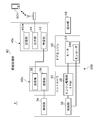
- FIG. 2 is a block diagram schematically illustrating the automatic door maintenance support system of FIG. 1.
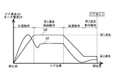
- FIG. 3 is a diagram illustrating an example of a transition of a door speed in the opening operation of the automatic door of FIG. 1.
- FIG. 2 is an explanatory diagram illustrating a method of estimating a maintenance time of the automatic door of FIG. 1.
- FIG. 2 is another explanatory diagram illustrating a method for estimating a maintenance time of the automatic door of FIG. 1.
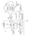
- It is a block diagram showing roughly the automatic door maintenance support system concerning a 2nd embodiment.
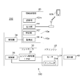
- It is a block diagram showing roughly the automatic door device concerning a 3rd embodiment.
- FIG. 8 is a flowchart showing a process of a computer program of the automatic door device of FIG. It is a front view showing roughly the automatic door to which the automatic door maintenance support system concerning a 10th embodiment was applied.
- FIG. 10 is a block diagram schematically illustrating the automatic door maintenance support system of FIG. 9.
- FIG. 10 is a diagram illustrating an example of a relationship between a stroke and a door speed of the automatic door in FIG. 9.
- FIG. 10 is a diagram illustrating another example of the relationship between the stroke and the door speed of the automatic door in FIG. 9.
- One embodiment of the present invention relates to an automatic door maintenance support system.
- This system includes an acceleration region in which the door of the automatic door is accelerated to a predetermined first speed (acceleration control state), a high-speed region in which the door is maintained at the first speed (first speed control state), A motor that drives a door in at least one of a deceleration range where the speed is reduced to a low second speed (deceleration control state) and a deceleration range where the speed is maintained at the second speed (second speed control state)
- An information acquisition unit that acquires information about the state of the motor (hereinafter, referred to as “state information”), and a specification unit that specifies information about maintenance of the automatic door by illuminating the acquired state information of the motor with a predetermined reference value. .
- the system may assist in maintaining one or more automatic doors.
- the predetermined first speed may be a relatively high speed after the door has been accelerated.
- the motor state information may be an electric numerical value of the motor, or may
- the state information of the motor described above may be acquired at a plurality of timings in at least one of the control states of the acceleration range, the high speed range, the deceleration range, and the low speed range.
- the evaluation since the evaluation is performed at a plurality of points instead of one point in the speed range, various information such as obtaining the power consumption of the motor from the motor voltages at multiple points can be obtained.
- the plurality of timings may be an intermediate timing of each speed range and a switching timing between the speed ranges.
- the motor state information in each speed range (each control state) is used. It is possible to improve the accuracy of condition diagnosis and maintenance necessity prediction. In particular, by using the state information of the motor, it is possible to configure without using a large additional device, and it is also possible to acquire the state change of the drive system and the electric system, and to isolate the portion where the condition is lowered.
- the status information can also be applied to the level evaluation of the necessity of maintenance.
- the motor status information can also be used to determine the quality of the automatic door installation, such as excessive belt tension.
- the above-described motor state information may be acquired when the control state of the acceleration range, the high speed range, the deceleration range, and the low speed range is switched. In this case, by acquiring at the time of switching, the acquisition timing becomes constant, and errors due to fluctuations in the acquisition timing can be suppressed. Further, since information is acquired at the time of switching, the amount of information is always smaller than in the case of acquiring information, and storage and processing thereof are facilitated.
- the above-mentioned reference value may be set or updated according to the motor status information acquired in the past.
- the reference value since the reference value is set based on the state information of the own motor, it is hard to be affected by individual performance differences (variation during manufacturing) of the automatic door. For example, if an initial acquisition value is used as a reference value, information can be acquired as a change from the initial value.
- by appropriately updating the reference value it is possible to eliminate the influence of variations due to environmental fluctuations such as summer and winter.
- the system described above may include a presentation unit that presents status information of the automatic door.
- a presentation unit that presents status information of the automatic door.
- the state information of the motor described above may include at least one of state information of voltage, current, rotation speed, vibration, and temperature of the motor.
- the state information of the automatic door can be specified from the state information of the voltage, current, rotation speed, vibration and temperature of the motor.
- the above-described specifying unit may classify the acquired motor state information based on a threshold value.
- the state of the motor can be accurately determined by classifying the state information by a threshold value and using the classification result.
- the threshold may be a limit above which replacement is recommended.
- Another embodiment of the present invention is an automatic door maintenance support device.
- This device includes an acceleration control state in which an automatic door is accelerated to a first speed, a first speed control state in which the door is maintained at a first speed, and a deceleration in which the speed is reduced to a second speed lower than the first speed.
- An acquisition unit that acquires state information of a motor that drives a door in at least one of a control state and a second speed control state that is held at a second speed; and acquires the acquired state information of the motor.
- an output unit for outputting For example, the automatic door maintenance support device may acquire the state information from the motor of the automatic door, and output the acquired result from the output unit to the management center.
- the management center can analyze the obtained result and specify the necessity of maintenance of the automatic door.
- the output unit may output the obtained result to a predetermined memory and store the obtained result in the memory.
- the serviceman can determine the necessity of maintenance of the automatic door from the result of storage in the memory.
- the method includes an acceleration control state in which the door of the automatic door is accelerated to a first speed, a first speed control state in which the door is maintained at the first speed, and a deceleration in which the door is reduced to a second speed lower than the first speed. Acquiring at least one of the control state and the second speed control state held at the second speed by using a sensor to obtain state information of the motor driving the door; and Identifying the information on maintenance of the automatic door by comparing the status information with a predetermined reference value.
- the accuracy of the state diagnosis of the automatic door and its components and the prediction of the necessity of the maintenance are compared with the case where the failure diagnosis is simply performed based on the number of times of opening and closing. Can be improved.
- Another aspect of the present invention is also an automatic door maintenance support method.
- the method includes an acceleration control state in which the door of the automatic door is accelerated to a first speed, a first speed control state in which the door is maintained at the first speed, and a deceleration in which the door is reduced to a second speed lower than the first speed.
- a step of monitoring the behavior of the electric numerical value of the motor driving the door based on the behavior And identifying the state information of the automatic door.
- the electric numerical value of the motor in each control state (speed range)
- the state diagnosis and maintenance of the automatic door and its components are compared with the case where the failure diagnosis is simply performed based on the number of times of opening and closing.
- the accuracy of the necessity prediction can be improved.
- the electrical value for the motor may include any of the voltage, current, rotation speed, vibration, and temperature of the motor.
- the motor status information may be an electrical numerical value corresponding to the motor status.
- the electrical value may be a motor torque, a motor power consumption, a motor drive current (hereinafter simply referred to as “current”), a motor drive voltage, or the like.
- the predetermined reference value may be a reference value set at the time of installation or maintenance of the automatic door, or may be a reference value updated and set at a predetermined time or when a predetermined event occurs. Is also good.
- the accuracy of the state diagnosis of the automatic door and its components and the prediction of the necessity of maintenance can be improved as compared with the case of performing a failure diagnosis or the like simply based on the number of times of opening and closing.
- this component includes a door roller of an automatic door, a traveling rail on which the door roller travels, a gear mechanism between a motor and a driving pulley, a driving pulley, a driven pulley, a timing belt, a guide rail that guides a lower portion of the door, around the door. Rubber packing and the like are provided.
- each part of the motor it is possible to estimate the deterioration state of each part of the motor.
- the state of deterioration of each part include deterioration of the field magnet of the motor, deterioration of the armature coil, and decrease of the lubricating oil of the rotating part.
- the above-mentioned reference value may be set according to information on the state of the motor acquired in the past (hereinafter, referred to as “past information”).
- the reference value may be set by adding a predetermined value to past information, or may be set by multiplying past information by a predetermined value.
- the predetermined value by which the past information is multiplied may be one or more values.
- This reference value may be set after maintenance work such as installation and maintenance of an automatic door (hereinafter simply referred to as “maintenance”).
- the term “after installation or maintenance” may be immediately after the installation or maintenance, or may be after a certain number of times (for example, 100 times) of opening and closing after installation or maintenance.
- the reference value may be an average value, a median value, or a specific value of the state information at the time of opening and closing a certain number of times after installation and maintenance after opening and closing.
- the specific value may be a value specified from information within a certain range among the respective pieces of state information.
- the reference value is not limited to after the installation or maintenance, but may be set at a predetermined time or when a predetermined event occurs.
- the above-mentioned reference value may be set according to information on the state of the motor acquired after opening and closing operations for a predetermined number of times.
- the reference value can be set after the hardness of a member made of a material having a large temperature characteristic such as rubber or the viscosity of grease applied to the movable portion is stabilized, so that accurate determination can be made.
- a member made of a material having a large temperature characteristic such as rubber or the viscosity of grease applied to the movable portion is stabilized, so that accurate determination can be made.
- examples of such a member include a door roller made of rubber, and examples of such grease include grease applied to a shaft or a bearing of a motor.
- the above-mentioned specifying unit may specify using a threshold.
- the threshold may be set according to at least two combinations of the weight of the door, the area of the main surface of the door, the aspect ratio of the main surface of the door, the installation environment of the door, and the type of the automatic door. In this case, the influence of the error due to the installation environment of the automatic door can be reduced.
- the identification unit may determine whether or not the deviation between the above-described reference value and the motor state information exceeds a threshold.
- the main surface of the door refers to the surface having the largest area among the respective surfaces of the door
- the type of the automatic door is set according to the capacity of the controllable motor, and other than the motor driving circuit. Are set depending on the difference in the circuit configuration.
- the above-described specifying unit may estimate the time at which maintenance should be performed based on the frequency of opening and closing the door. In this case, it is possible to predict the recommended maintenance time and the replacement time of the member.
- This opening / closing frequency may be a value obtained by evaluating the opening / closing frequency of the specific object automatic door itself for a certain period, or a value set as an estimation parameter for the specific object. You may. A value obtained by evaluating these or a set value may be stored in the storage unit as a frequency value.
- the specifying unit may estimate the time when maintenance should be performed using the stored frequency value.
- the maintenance time may be the recommended maintenance time.
- Either the threshold value, the maintenance time, or the opening / closing frequency can be set as one of the parameters. Therefore, the above-described threshold may be set based on the opening / closing frequency.
- the maintenance time may be set as a predetermined period (for example, six months or one year), and a threshold value may be set according to the predetermined period and the frequency value described above.
- the frequency of opening and closing of automatic doors of tourist facilities, leisure facilities, and the like greatly differs depending on the season, or between busy periods and non-busy periods. Also, depending on the season, it may be used while being opened or closed. For this reason, the above-mentioned opening / closing frequency may be updated at predetermined intervals. In this case, it is possible to cope with seasonal variations in the opening and closing frequency.
- the above-described frequency value may be updated with a value obtained by re-evaluating the opening / closing frequency of the target automatic door or a newly set value.
- the predetermined interval may be determined by a period during which the frequency of opening and closing of the automatic door changes, such as one month, three months, and six months.
- the above-described specifying unit may also evaluate a change in information on the state of the motor.
- a deteriorated portion can be specified to some extent.
- a fluctuation cycle can be specified by analyzing a pattern of a state fluctuation.
- a frequency analysis by Fourier transform can be used.
- the rotation cycle component of the door wheel, the rotation cycle component of the pulley, the rotation cycle component of the motor, or the non-periodic component is confirmed in the state fluctuation, it is considered that the member related to the component has deteriorated. it can.
- efficient and accurate maintenance work can be performed.
- the acquisition unit described above may acquire information on the state of the motor even in the second speed control state in which the door is held at the second speed lower than the first speed.
- the deteriorated part can be specified to some extent.
- the different speeds may be the first speed and the second speed described above.
- the acquisition unit may acquire the state information in the first speed control state held at the first speed and the state information in the second speed control state held at the second speed.
- the state information changes proportionally to the speed, it can be considered that the magnet or coil of the motor has deteriorated, and when it does not change proportionally, it can be considered that the mechanical system has deteriorated.
- the information on the state of the motor described above may be information on a current flowing through the motor.
- the state information can be easily detected without separately providing a sensor.
- the current flowing through the motor (hereinafter, referred to as “motor current”) can be detected by a current sensor provided in a path through which the current flows.
- the current sensor may be a shunt resistor connected in series with the motor.
- the motor current may be obtained from a drive voltage applied to the motor.
- the motor current may be calculated from the duty ratio of the drive voltage of the motor.
- the acquisition unit described above may acquire information on the state of the motor even in a deceleration control state in which the motor is decelerated from the first speed.
- a deceleration control state in which the motor is decelerated from the first speed.
- the state information in the deceleration control state it is possible to identify the deteriorated part to some extent. For example, when the mechanical system is deteriorated and the load is increasing, the deceleration becomes large, and when the motor is deteriorated, the deceleration becomes small. Therefore, the deteriorated portion can be specified based on the difference between them.
- a presentation unit may be provided for presenting the specified result of the above-described specified unit, and the presentation unit may be arranged near the door.
- the deterioration status can be recognized by the owner, the user, the manager, and the like of the automatic door.
- the presentation unit may be a notification device that emits light or sound, or a display device that outputs images or sound.
- the presentation unit may be provided on a blind, frame, pillar, wall, or the like of the automatic door.
- An output unit for outputting the specified result of the specified unit may be provided.
- the degradation status can be notified to a remote location.
- the output unit may output the specified result to an external device by a wired or wireless communication means, or may transmit an e-mail.
- This communication means may include a network such as the Internet.
- This communication means may output the specified result by short-range wireless communication.
- the external device may be a computer, a server, a cloud, or the like provided separately from the automatic door, or may be a mobile terminal or a smartphone possessed by a service person.
- a transmission unit that transmits the acquisition result of the acquisition unit to the cloud server may be provided.
- the acquisition unit may be provided at or near the automatic door, and the identification unit may be provided at the cloud server.
- the threshold can be easily updated.
- the state information can be analyzed by an advanced technique such as Fourier analysis.
- the transmission unit may transmit the acquisition result (state information) of the acquisition unit to the cloud server via the communication unit and the network.
- the cloud server is not particularly limited as long as it is a server provided on a cloud environment.
- This device includes an opening / closing mechanism including a door, a driving mechanism for opening and closing the door with a motor, a control unit for controlling the motor, and motor state information in a speed control state in which the door is held at a predetermined speed by the control unit. And an identification unit that illuminates the acquired state information with a predetermined reference value and identifies information related to automatic door maintenance.
- the opening / closing mechanism may include a door, a door roller that supports the door, and a rail on which the door roller runs.
- the driving mechanism includes a motor, a driving pulley driven by the motor, a driven pulley provided in a pair with the driving pulley, a belt wound around the driving pulley and the driven pulley, and a connecting portion connecting the belt and the door. It may be. According to this aspect, since acquisition and identification are performed within the range of the automatic door, connection between the acquisition unit and the identification unit is facilitated and the configuration is simplified as compared with a case where the identification unit is separately provided outside. Can be. That is, it is not necessary to separately provide a maintenance support system.
- Another aspect of the present invention is an automatic door maintenance support method.
- the method includes the steps of acquiring state information of a motor that drives the door in a speed control state in which the door of the automatic door is held at a predetermined speed, and illuminating the acquired state information with a predetermined reference value, Identifying information regarding maintenance of the door.
- the state information since the state information is used, the accuracy of the state diagnosis of the automatic door and its components and the prediction of the necessity of maintenance can be improved as compared with the case of performing a failure diagnosis or the like simply based on the number of times of opening and closing.
- Another embodiment of the present invention is a program for causing a computer to execute an automatic door maintenance support method.
- the program includes a step of acquiring state information of a motor driving the door in a speed control state in which the door of the automatic door is held at a predetermined speed, and illuminating the acquired state information with a predetermined reference value, Identifying information regarding maintenance of the door.
- the state information since the state information is used, the accuracy of the state diagnosis of the automatic door and its components and the prediction of the necessity of maintenance can be improved as compared with the case of performing a failure diagnosis or the like simply based on the number of times of opening and closing.
- FIG. 1 is a front view schematically showing an automatic door 100 to which the automatic door maintenance support system 1 according to the first embodiment is applied.
- FIG. 2 is a block diagram schematically showing the automatic door maintenance support system 1.
- Each of the functional blocks shown in FIG. 2 can be realized in terms of hardware by electronic elements such as a CPU of a computer, mechanical parts, and the like, and can be realized by software such as a computer program.
- the functional blocks realized by cooperation are drawn. Therefore, it is understood by those skilled in the art that these functional blocks can be realized in various forms by a combination of hardware and software. The same applies to functional blocks in FIGS. 6 and 7 described later.
- the automatic door maintenance support system 1 includes an automatic door 100 and an information processing unit 40.
- the automatic door 100 is driven by a motor 24 to open and close the door 12.
- the information processing section 40 processes information relating to the state of the motor 24 (hereinafter, referred to as “state information Li”). First, the automatic door 100 will be described, and the information processing unit 40 will be described later.
- the automatic door 100 includes a door engine 10, a door 12, a belt 14, a driving pulley 16, a driven pulley 18, a traveling rail 20, a suspension unit 22, a controller 30, a door sensor 32, a presentation unit 48, , A guide rail 82 and a rubber packing 84.
- the movable direction of the door 12 of this embodiment is parallel to the horizontal X-axis direction.
- the expected direction of the door 12 is parallel to a horizontal Y-axis direction orthogonal to the X-axis direction.
- the vertical direction of the door 12 is parallel to the Z-axis direction orthogonal to the X-axis direction and the Y-axis direction.
- Such notation of the direction does not limit the use posture of the automatic door 100, and the automatic door 100 can be used in any posture depending on the application.
- the presentation unit 48 will be described later.
- the door engine 10 includes a motor 24 and a gear mechanism (not shown) that drives the drive pulley 16 to rotate based on the rotation of the motor 24.
- the door engine 10 functions as a power source for opening and closing the door 12 by the driving force of the motor 24.
- the motor 24 is driven by an IPM (intelligent power module) provided in an engine drive unit 28 described later.
- the motor 24 may be a motor based on various known principles.
- the motor 24 of the present embodiment is a brushless motor having an encoder 24e using a Hall IC.
- the driven pulley 18 is provided apart from the driving pulley 16 in the X-axis direction.
- the belt 14 is looped around the outer circumference of the driving pulley 16 and the driven pulley 18.
- the belt 14 rotates the driven pulley 18 as the driving pulley 16 rotates.
- the belt 14 may be a timing belt with teeth.
- the running rail 20 is a rail member for guiding the door 12 above the door 12, and extends in the movable direction of the door 12 (X-axis direction).
- the suspension unit 22 is a mechanism for suspending the door 12 on the traveling rail 20, and is provided above the door 12.
- the suspension unit 22 has a door roller 22c that rolls on the traveling rail 20, and is supported by the traveling rail 20 via the door roller 22c.
- the door 12 is connected to the belt 14 via a connecting member 12j.
- the door sensor 32 is attached to the blind 80 or the like, and detects a pedestrian or the like.
- the controller 30 opens and closes the door 12 by controlling the motor 24 of the door engine 10 according to the detection result of a pedestrian or the like from the door sensor 32.
- the controller 30 includes an engine drive unit 28 that drives the motor 24 of the door engine 10, a control unit 26 that controls the operation of the automatic door 100, and a detection unit 34 that detects state information Li of the motor 24.
- the detection unit 34 will be described later.
- the guide rail 82 is a rail having a groove extending in the X-axis direction for guiding the steady rest 12 s extending from the lower part of the door 12.
- the rubber packing 84 is provided around the door 12 or the like mainly to improve airtightness. When the door 12 moves, the rubber packing 84 rubs against either the movable part or the fixed part.
- the automatic door 100 configured as described above, when the motor 24 drives the drive pulley 16 to rotate, the drive pulley 16 and the driven pulley 18 rotate, and the belt 14 moves in a loop.
- the suspension part 22 suspended on the belt 14 via the connecting member 12j moves on the traveling rail 20 in the X-axis direction.
- the door 12 moves in the X-axis direction together with the suspension unit 22 to perform an opening / closing operation.
- door speed Vd is proportional to the rotation speed of the motor 24.
- the automatic door 100 opens the door 12 when the door sensor 32 detects a pedestrian or the like, and closes the door 12 at a predetermined timing when the door sensor 32 stops detecting a pedestrian or the like.
- FIG. 3 is a diagram illustrating an example of a change in the door speed Vd of the door 12 during the opening operation.
- the horizontal axis represents the position from the closed position to the open position of the door 12 (hereinafter referred to as “door position”)
- the vertical axis represents the door speed Vd of the door 12 and the current for driving the motor 24 (hereinafter, referred to as “door position”).
- door position represents the position from the closed position to the open position of the door 12
- door position the current for driving the motor 24
- the opening operation of the present embodiment includes an accelerating operation for accelerating the door 12 stopped at the closed position to a predetermined first speed, a first speed control operation for maintaining the first speed, and a deceleration for decelerating to the second speed.
- This includes an operation, a second speed control operation for maintaining the second speed, and a door hitting operation for stopping the door 12 by contacting the door 12 with a stopper (not shown).
- the acceleration operation, the first speed control operation, the deceleration operation, the second speed control operation, and the door hit operation are collectively referred to as “each operation”.
- the first speed is higher than the second speed, and the second speed is lower than the first speed.
- the automatic door 100 keeps the speed Vd of the door 12 constant at the first speed. This state is called a first speed control state.
- the automatic door 100 keeps the speed Vd of the door 12 constant at the second speed. This state is called a second speed control state.
- the first speed control state and the second speed control state are collectively referred to as “each control state”.
- the operation In the acceleration operation, when the speed Vd reaches the first speed, the operation is switched to the first speed control operation.
- the first speed control operation when the door position reaches the predetermined position, the operation is switched to the deceleration operation.
- the deceleration operation when the speed reaches the second speed, the operation is switched to the second speed control operation.
- the second speed control operation the door 12 is moved to the open position. When the door 12 reaches the open position, the door 12 comes into contact with the stopper and stops by the door contact operation.
- the supply voltage to the motor 24 (hereinafter simply referred to as “motor voltage”) is controlled such that the relationship between the door position and the door speed Vd follows a predetermined acceleration curve.
- the motor voltage is pulse width modulated (PWM modulated) and is controlled by its duty ratio.
- PWM modulated pulse width modulated
- the motor 24 may be subjected to constant voltage control, constant current control, or constant acceleration control. In this operation, as shown in FIG. 3, the motor current Id increases as the door speed Vd increases.
- the motor voltage is controlled so as to suppress the fluctuation.
- the motor 24 may be controlled at a constant speed. This control may be control for feeding back the detected motor speed or control not including feedback.
- the first speed may be the maximum moving speed of the door 12 or a speed close thereto. In this operation, as shown in FIG. 3, the motor current Id is substantially constant, although there is some variation.
- the motor voltage is controlled so that the relationship between the door position and the door speed Vd follows a predetermined deceleration curve. In this operation, the motor voltage is gradually reduced, and the speed is reduced by the sliding load of the door 12 or the like.
- the brake torque may be generated by a short brake operation that short-circuits the back electromotive force of the motor 24, or the brake torque may be generated by supplying the motor 24 with a voltage having a polarity opposite to that during acceleration. .
- the motor 24 may be controlled by constant voltage control, constant current control or constant acceleration control. In this operation, as shown in FIG. 3, the motor current Id decreases as the door speed Vd decreases.
- the motor voltage is controlled so as to suppress the fluctuation.
- the motor 24 may be controlled at a constant speed.
- the door 12 that moves at the second speed is brought into contact with the stopper to stop the door 12.
- the second speed may be a speed lower than the first speed, for example, a slow speed in which the door 12 stops in a short time, in order to reduce an impact when the door 12 is brought into contact with the stopper.
- the motor current Id is substantially constant, although there is some variation.
- the door 12 comes into contact with the stopper at the open position and stops. A slight change in position of the door 12 may occur due to the recoil of the contact.
- electric power enough to maintain the door 12 at the open position may be supplied to the motor 24, or power supply to the motor 24 may be stopped. This power supply may be temporary or continuous.
- the closing operation is an operation in which the door 12 is moved from the open position to the closed position and stopped.
- the closing operation is different from the opening operation in that the moving direction of the door 12 is opposite, and, like the opening operation, the acceleration operation, the first speed control operation, the deceleration operation, the second speed control operation, and the door contact operation. And Each of these operations is similar to the opening operation, and redundant description is omitted.
- the information processing unit 40 processes the state information Li of the motor 24 to support maintenance of the automatic door 100.
- Some or all of the components of the information processing unit 40 may be provided integrally with the controller 30, may be provided separately from the controller 30, or may be provided separately from the automatic door 100. Good.
- the acquisition unit 36 and the transmission unit 38 are provided in a first block 40b integrated with the controller 30.
- the identification unit 42, the output unit 44, and the storage unit 40m are provided in a second block separate from the controller 30. 40c.
- the second block 40c is provided in a computer of a management center that manages one or a plurality of automatic doors.
- the acquisition unit 36 acquires the state information Li of the motor 24 detected by the detection unit 34.
- the acquisition unit 36 acquires the state information Li of the motor 24 that drives the door 12 in the first speed control state and the second speed control state.
- the state information Li of the present embodiment is the motor current Id.
- the acquisition unit 36 of the present embodiment acquires the state information Li from the detection result of the detection unit 34.
- the detection unit 34 can detect the motor current Id as a voltage drop of a shunt resistor (not shown) connected in series to the motor 24.
- the acquisition unit 36 can acquire the door speed Vd according to the cycle and frequency of the output signal of the encoder 24e of the motor 24.
- the acquisition unit 36 can acquire the door position of the door 12 by counting the output signal of the encoder 24e.
- the transmission unit 38 transmits the acquisition result of the acquisition unit 36 to the identification unit 42 via a network or a data bus.
- the acquisition result of the acquisition unit 36 is also the state information Li.
- the identification unit 42 illuminates the state information Li acquired by the acquisition unit 36 with a predetermined reference value Ls, and identifies information on maintenance of the automatic door 100.
- the specifying unit 42 specifies the information on the maintenance of the automatic door 100 by illuminating the state information Li with the reference value Ls.
- the reference value Ls of the present embodiment is a reference value set when the automatic door 100 is installed or when the automatic door 100 is maintained.
- the specifying unit 42 determines that maintenance is necessary when the deviation of the state information Li from the reference value Ls is large, and determines that maintenance is unnecessary when the deviation is small.
- the specifying unit 42 may determine that maintenance is required within a certain period when the deviation is medium.
- the output unit 44 outputs the specified result Sj of the specified unit 42 to the outside.
- the output unit 44 outputs the identification result Sj of the identification unit 42 to the presentation unit 48.
- the presentation unit 48 presents the specified result Sj.
- the presenting unit 48 of the present embodiment is arranged in a frame near the door 12, and has an LED 48b.
- the presentation unit 48 presents the specific result based on the lighting state of the LED 48b. In this example, the LED 48b is illuminated in green when maintenance is not required, the LED 48b is illuminated in yellow when maintenance is required within a certain period, and the LED 48b is illuminated in red when maintenance is required early.
- the output unit 44 outputs the specified result Sj to the information terminal 60h via the communication unit.
- the output unit 44 may transmit the specified result Sj as an e-mail to the information terminal 60h.
- the information terminal 60h may be a desktop type or may be portable by a service person. By displaying the identification result Sj on the information terminal 60h carried by the service person, it is possible to easily grasp the abnormality of the automatic door 100 and the necessity of maintenance. In this case, the abnormality of the automatic door and the necessity of maintenance can be easily explained to the owner of the automatic door.
- the storage unit 40m stores a reference value Ls, state information Li, a specified result Sj, a threshold Lt, and an opening / closing frequency F, which will be described later.
- the reference value Ls will be described.
- the reference value Ls may be set to a value calculated on design.
- the reference value Ls may be set to an average value of the state information of the motors of a plurality of other automatic doors of the same type.
- the reference value Ls is set according to the state information Li of the motor 24 itself acquired in the past.
- the reference value Ls is set in the state information of the motor 24 itself acquired at the time of installing the automatic door 100 or at the time of maintenance.
- the state information used for the reference value Ls may be acquired immediately after the installation and maintenance of the automatic door 100, but in this example, the opening / closing operation is performed a predetermined number of times (for example, 100 times) from the installation and maintenance of the automatic door 100. This is the state information obtained after the operation.
- the reference value Ls may be set in the state information at the time of one opening / closing operation, but in this example, the reference value Ls is an average value of a plurality of state information at the time of performing the opening / closing operation a plurality of times.
- the reference value Ls may be constant until the next maintenance. However, the state of the motor has a temperature characteristic, and may increase when the air temperature is low and decrease when the air temperature is high. Therefore, the reference value Ls may be updated every predetermined season.
- the set or updated reference value Ls is stored in the storage unit 40m.
- the specifying unit 42 of the present embodiment classifies the deviation of the state information Li from the reference value Ls using one or a plurality of thresholds Lt, and sets the classification result as the specification result Sj.
- the specifying unit 42 is configured to perform a notification prompting maintenance (hereinafter, referred to as “maintenance notification”).
- the threshold value Lt may be set to a value calculated on design.
- the speed of wear and deterioration of the components of the automatic door differs depending on the weight of the door, the magnitude of the wind pressure applied to the door, and the like.
- the threshold Lt is determined by the weight of the door 12, the area of the main surface of the door 12, the aspect ratio of the main surface of the door 12, the installation environment of the door 12 (such as a salt damage area), and the type of the automatic door 100. Can be set according to a combination of at least two of.
- the threshold Lt is set based on factors selected from these in accordance with the situation of the installation site of the automatic door 100.
- the threshold value Lt may be constant once set, but the rate of wear and deterioration may change due to various factors. For this reason, the threshold Lt may be updated in accordance with a change state of the factor.
- the set or updated threshold value Lt is stored in the storage unit 40m.
- FIGS. 4 and 5 are explanatory diagrams illustrating a method of estimating the maintenance time.
- the horizontal axis indicates elapsed time, and the vertical axis indicates state information.
- Lines indicated by reference signs A and B are prediction lines of the state information change with respect to the elapsed time.
- A1 and B1 are timings when the state information Li is detected, and are referred to herein as “detection timings”.
- A2 and B2 are timings at which the predicted lines A and B exceed the threshold Lt, and are timings at which maintenance notification is performed (hereinafter, referred to as "notification timing").
- A3 and B4 are timings at which the prediction lines A and B reach the limit value Lg, and are referred to herein as "limit times".
- the limit value Lg is a value which is assumed to have a high possibility of causing a failure when it reaches this value.
- $ P1 and P2 indicate the period from the notification time to the limit time (hereinafter referred to as "remaining period P").
- FIG. 4 shows a case where the threshold Lt is the same for the prediction lines A and B, and the remaining period P1 is shorter than the remaining period P2.
- FIG. 5 shows a case where the threshold Lt is different between the prediction lines A and B, and the remaining period P1 is equal to the remaining period P2.
- the inclination of the prediction lines A and B differs depending on the speed of wear and deterioration of the components of the automatic door (hereinafter referred to as “deterioration speed D”).
- the deterioration speed D is considered to be substantially proportional to the opening / closing frequency F of the door 12, and can be replaced with the product of the proportionality constant k and the opening / closing frequency F.
- the prediction line A has a higher opening / closing frequency F and a higher degradation speed D than the prediction line B, and thus has a shorter remaining period. From these, the remaining period P can be obtained from the limit value Lg, the threshold value Lt, and the deterioration speed D as shown in Expression 1.
- Remaining period P (limit value Lg ⁇ threshold value Lt) / deterioration speed D (Equation 1)
- Remaining period P (limit value Lg ⁇ threshold value Lt) / (k ⁇ opening / closing frequency F) (formula 2) From Equation 2, the remaining period P can be set according to the opening / closing frequency F.
- the threshold Lt is set based on the opening / closing frequency F so that the maintenance notification is performed when the remaining period P reaches a certain period. This fixed period may be, for example, 3 months, 6 months, 12 months, or the like.
- FIG. 5 shows a case where the threshold value Lt is changed according to the opening / closing frequency F.
- the threshold Lt is lower in the predicted line A having the higher opening / closing frequency F than in the predicted line B having the lower opening / closing frequency F.
- the remaining period P1 is substantially equal to the remaining period P2.
- the threshold Lt for keeping the remaining period P constant can be obtained from the limit value Lg, the remaining period P, and the deterioration speed D as shown in Expression 3.
- Threshold value Lt limit value Lg ⁇ remaining period P ⁇ deterioration speed D ⁇
- Threshold Lt limit value Lg ⁇ remaining period P ⁇ (k ⁇ opening / closing frequency F) (Equation 4) From Expression 4, the threshold Lt can be set according to the opening / closing frequency F.
- the opening / closing frequency F to be substituted into the above formulas 2 and 4 is initially set as one of the parameters.
- the opening / closing frequency F may be constant as it is initially set. However, the opening / closing frequency F may vary greatly depending on the season, or between a busy period and a non-busy period. Therefore, the opening / closing frequency F of the present embodiment is updated at predetermined intervals.
- the update interval of the opening / closing frequency F is set according to a period in which the opening / closing frequency of the automatic door changes, such as one month, three months, six months, or the like.
- the set or updated opening / closing frequency F is stored in the storage unit 40m.
- the identification unit 42 of the present embodiment also evaluates the fluctuation of the state information Li of the motor 24.
- a rotation cycle component of the door pulley 22c, a rotation cycle component of the drive pulleys 16 and 18, a rotation cycle component of the motor 24, and the like are extracted by frequency-analyzing the fluctuation of the state information Li. If these rotation cycle components are detected remarkably, it can be specified that the members related to the rotation cycle have deteriorated.
- This frequency analysis can be realized by performing a Fourier transform on the state information Li stored in the storage unit 40m in time series. If the non-periodic component is remarkably detected, deterioration of the traveling rail 20, the belt 14, the steady rest 12s, the guide rail 82, the rubber packing 84, and the like may be considered.
- the acquisition unit 36 of the present embodiment acquires the state information Li of the motor 24 even in the second speed control state in which the door 12 is maintained at the second speed lower than the first speed.
- the state information Li of the first and second speeds changes in proportion to the speed Vd of the door 12
- the magnet (not shown) or the coil (not shown) of the motor 24 has deteriorated, and the change in proportion to the change. If not, it can be specified that the mechanical system has deteriorated.
- the acquisition unit 36 of the present embodiment acquires the state information Li of the motor 24 even in the deceleration control state in which the motor 24 is decelerated from the first speed.
- the deceleration is large, it can be specified that the mechanical system has deteriorated, and when the deceleration is small, it can be specified that the magnets and coils of the motor 24 have been deteriorated.
- the opening operation or the closing operation is performed at a predetermined timing on a daily basis, the state information Li of the motor 24 is obtained, and the obtained state information Li is lit against the reference value Ls. Then, information on maintenance of the automatic door 100 is specified. This operation may be performed as a regular operation, for example, when the automatic door 100 starts or closes.
- the specified result Sj is presented to the presentation unit 48 and the information terminal 60h. A serviceman, an administrator, or the like may create a maintenance plan by confirming the necessity of maintenance according to the specified result Sj.
- state information Li and the specific result Sj may be stored in chronological order.
- Features such as the deterioration speed of the automatic door 100 can be specified from the state information Li stored in chronological order. The above is the description of the first embodiment.
- FIG. 6 is a block diagram schematically showing the automatic door maintenance support system 2, and corresponds to FIG.
- the same or equivalent components and members as those of the first embodiment are denoted by the same reference numerals.
- the description overlapping with the first embodiment will be omitted as appropriate, and the configuration different from the first embodiment will be mainly described.
- the acquisition unit 36 and the transmission unit 38 are provided at or near the automatic door 100, and the identification unit 42, the output unit 44, and the storage unit 40m are provided in the cloud server 50.
- the transmission unit 38 of the present embodiment transmits the result of acquisition (state information Li) of the acquisition unit 36 to the cloud server 50 via the network NW.
- the output unit 44 of the present embodiment outputs the specified result Sj of the specified unit 42 to the information terminal 60h via the network NW.
- the second embodiment differs from the first embodiment in these points, and other configurations are the same.
- the second embodiment configured as described above operates in the same manner as the first embodiment, and has the same operation and effect as the first embodiment.
- FIG. 7 is a block diagram schematically showing the automatic door device 200, and corresponds to FIG.
- the same or equivalent components and members as those of the first embodiment are denoted by the same reference numerals.
- the description overlapping with the first embodiment will be omitted as appropriate, and the configuration different from the first embodiment will be mainly described.
- the acquisition unit 36, the identification unit 42, the output unit 44, and the storage unit 40m are provided at or near the automatic door 100. These may be provided integrally with the controller 30.
- the functions of the acquiring unit 36 and the specifying unit 42 are realized by a computer 40e in hardware, and are realized by a program 40p of the computer 40e in software.
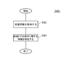
- FIG. 8 is a flowchart showing the processing S80 of the program 40p.
- the processing S80 of the program 40p includes a step S82 in which the door 12 of the automatic door 100 acquires the state information Li of the motor 24 driving the door 12 in the first speed control state, and the acquired state information Li is set to the reference value Ls.
- step S84 of identifying information relating to maintenance of the automatic door 100 The operations of steps S82 and S84 are the same as the operations of the acquisition unit 36 and the identification unit 42 described above, and redundant description will be omitted.
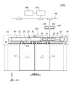
- FIG. 9 is a front view schematically showing an automatic door 100 to which the automatic door maintenance support system 1000 according to the third embodiment is applied.
- FIG. 10 is a block diagram schematically showing the automatic door maintenance support system 1.
- the automatic door maintenance support system 1000 includes a maintenance support device 140, a specifying unit 150, instead of the information processing unit 40 of the automatic door maintenance support system 1 of FIGS. And a presentation unit 160.
- the automatic door 100 is driven by a motor 24 to open and close the door 12.
- Other configurations of the information processing unit 40 of the automatic door maintenance support system 1000 are the same as those of the automatic door maintenance support system 1.
- the maintenance support device 140 acquires status information of the motor 24 to support maintenance of the automatic door 100.
- the maintenance support device 140 may be provided integrally with the controller 30, may be provided separately from the controller 30, or may be provided separately from the automatic door 100.
- the maintenance support device 140 according to the present embodiment includes an acquisition unit 136 that acquires the state information Mi of the motor 24, an output unit 138 that outputs the acquired state information Mi of the motor 24, and an acquired state information Mi of the motor 24. And a storage unit 140m for storing
- the state information Mi of the motor 24 may include at least one of a supply voltage (voltage Em), a driving current, a rotation speed, a rotation position, a vibration, and a temperature of the motor 24.
- the acquisition unit 136 of the present embodiment acquires the state information Mi from the detection result of the detection unit 134.
- the detection unit 134 of the present embodiment includes a voltage sensor 134a for detecting a supply voltage of the motor 24, a current sensor 134b for detecting a drive current of the motor 24, a speed sensor 134c for detecting the speed of the motor 24, It includes a vibration sensor 134d for detecting vibration and a temperature sensor 134e for detecting the temperature of the motor 24.
- the acquisition unit 136 of the present embodiment includes a voltage acquisition unit 136a that acquires the detection result of the voltage sensor 134a, a current acquisition unit 136b that acquires the detection result of the current sensor 134b, and a speed acquisition that acquires the detection result of the speed sensor 134c.
- Voltage sensor 134a detects voltage Em of motor 24 from its duty ratio.
- the current sensor 134b detects the drive current of the motor 24 as a voltage drop of a resistor (not shown, sometimes referred to as a shunt resistor) connected in series to the motor 24.
- the speed sensor 134c acquires the speed Vm (rotation speed) of the motor 24 according to the cycle and frequency of the output signal of the encoder (Hall IC) mounted on the motor 24. Since the door speed Vd is proportional to the speed Vm of the motor 24, it can be said that the speed sensor 134c detects the door speed Vd. Further, the rotational position of the motor 24 can be obtained by counting output signals of the encoder. In this case, the rotational position of the motor 24 over a plurality of rotations can also be detected.
- the door position (stroke value Sd) corresponds to the rotational position of the motor 24 and can be obtained by counting the output signal of the encoder.
- the temperature sensor 134e may be a sensor built in the IPM that drives the motor 24.
- the IPM may include a motor protection function such as overheat protection, short-circuit protection, overcurrent protection, and control power supply abnormality protection.
- the state information Mi may always be obtained. However, in this case, the amount of information to be obtained increases, and the capacity of the storage unit 140m required to store the information increases, which is disadvantageous in terms of size and cost. . Therefore, in the present embodiment, the state information Mi is obtained at a predetermined timing in each speed range. By doing so, the information amount of Mi can be reduced, and the capacity of the storage unit 140m can be suppressed.
- the state information Mi may be acquired at a plurality of timings.
- the state information Mi may be acquired at the timing corresponding to the intermediate position of the predetermined stroke value Sd and the end timing of each speed range.
- the diagnosis is performed based on the information of a plurality of timings, it is possible to improve the accuracy of diagnosing the presence or absence of an abnormality and the necessity of maintenance.
- the state information Mi in the speed range is evaluated not at one point but at multiple points, it is possible to obtain various information on the motor 24, such as calculating power consumption from voltages at multiple points.
- the maintenance support device 140 of the present embodiment acquires the state information Mi at the end timing of each speed range.
- the end of the speed range may be at the time of switching between a plurality of speed ranges.
- the maintenance support device 140 may acquire the state information Mi for each opening operation, may acquire it at a predetermined event, or may acquire it at a predetermined time.
- the state information Mi is acquired at the time of starting inspection of the automatic door 100.
- the state information Mi may be acquired when the automatic door which has been in the non-operation state is switched to the movable state and the test operation is performed several times. In this case, it is possible to reduce the influence of the temperature difference of the motor or the like due to the difference in the operation status immediately before.
- the state information Mi may be acquired at regular time during a time period when the operation rate is low, such as early in the morning.
- the acquisition operation of the state information Mi may be incorporated in the control sequence of the start-up inspection, and this acquisition operation may be automatically executed at the start-up inspection.
- the maintenance support device 140 stores the acquired state information Mi in the storage unit 140m.
- the maintenance support device 140 outputs the stored state information Mi to the specifying unit 150 described below via the communication unit.
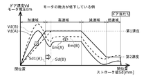
- FIG. 11 is a graph showing the door speed Vd and the voltage Em with respect to the movement stroke Sd (hereinafter, referred to as “stroke value Sd”) from the closed position to the open position of the door 12 in the opening operation.
- the solid line in this figure shows the door speed Vd (A) and the voltage Em (A) of the automatic door 100 (A) in the initial state where the motor 24 has not deteriorated.
- the broken lines in this figure indicate the door speed Vd (B) and the voltage Em (B) of the automatic door 100 (B) in a state where the performance of the motor 24 is reduced.
- the following diagnosis can be made from the graph of stroke versus speed / voltage in FIG. (1) Since the capacity of the motor 24 is low in the automatic door 100 (B), the voltage Em (B) of the automatic door 100 (B) in the high-speed range is higher than the voltage Em (A) of the automatic door 100 (A). (2) Since the capacity of the motor 24 is low in the automatic door 100 (B), the door speed Vd (B) of the automatic door 100 (B) corresponding to the same stroke value Sd in the acceleration range is the automatic door 100 (A). Is lower than the door speed Vd (A).
- a deterioration state (deterioration state) of the performance of the motor 24 according to the state information Mi of the motor 24 such as the door speed Vd and the voltage Em in each speed range.
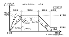
- FIG. 5 is a graph showing the door speed Vd and the voltage Em with respect to the stroke value Sd of the door 12 in the opening operation.
- the solid line in this figure shows the door speed Vd (A) and the voltage Em (A) of the automatic door 100 (A) in an initial state where the door wheel 22c is not worn.
- the broken lines in this figure show the door speed Vd (C) and the voltage Em (C) of the automatic door 100 (C) in a state where the door wheel 22c is worn.
- the following diagnosis can be made from the graph of stroke vs. speed / voltage in FIG. (1) Since the running resistance is high in the automatic door 100 (C), the voltage Em (C) of the automatic door 100 (C) in the acceleration region and the high speed region is higher than the voltage Em (A) of the automatic door 100 (A). . (2) Since the running resistance is high in the automatic door 100 (C), the door speed Vd (C) of the automatic door 100 (C) corresponding to the same stroke value Sd in the acceleration region is equal to the door speed of the automatic door 100 (A). The speed is lower than Vd (A).
- the present embodiment it is possible to diagnose an increase in running resistance due to abrasion of the door roller 22c or the like according to the state information Mi of the motor 24 such as the door speed Vd and the voltage Em in each speed range.
- FIG. 11 and FIG. 12 are compared, there is a difference in the voltage Em in the deceleration region as shown by the arrow 4 in FIG. That is, when the performance of the motor 24 is reduced, the voltage Em (B) is significantly higher than the voltage Em (A) even in the deceleration range.
- the running resistance is high, the vehicle is also decelerated by the running resistance, so that the voltage Em (C) can be smaller than the voltage Em (B) under the constant deceleration condition. Therefore, in the present embodiment, it is possible to determine which component condition is being reduced according to the magnitude of the voltage Em in the deceleration range.
- the specifying unit 150 may be provided integrally with the controller 30 or the maintenance support device 140, may be provided separately from the controller 30 or the maintenance support device 140, or may be provided separately from the automatic door 100. Is also good.
- the specifying unit 150 may be connected to the controller 30 or the maintenance support device 140 via a data bus, or may be connected via a communication network. This data bus or network may be wired or wireless.
- the communication network may be a public line or a dedicated line.
- the specifying unit 150 of the present embodiment is provided in a computer installed in a management center and connected to the maintenance support device 140 via a communication network NW. In this case, one computer can support maintenance of a plurality of automatic doors.
- the communication network NW may include the Internet.
- the identification unit 150 identifies the state information Di of the automatic door 100 according to the state information Mi of the motor 24 in order to support maintenance of the automatic door 100.
- the status information Di of the automatic door 100 is information on the status of the automatic door 100, and may be, for example, information on maintenance of the automatic door 100.
- the state information Di of the automatic door 100 is information on the necessity of maintenance such as necessity of maintenance and timing of maintenance.
- the specifying unit 150 of the present embodiment specifies the automatic door state information Di by illuminating the motor state information Mi acquired by the acquiring unit 136 with a predetermined reference value Si. In this case, the state information Di of the automatic door 100 can be specified with higher accuracy than in the case where the diagnosis is simply made based on the number of times of opening and closing.
- the identification unit 150 includes a second storage unit 152 and a calculation unit 154.
- the second storage unit 152 stores the reference value Si, the acquired state information Mi of the motor 24, and the identified state information Di of the automatic door 100.
- the calculation unit 154 specifies the state information Di of the automatic door 100 according to the reference value Si and the state information Mi of the motor 24.
- the reference value Si may be set according to motor status information of another automatic door having the same configuration as the automatic door 100.
- the reference value Si of the present embodiment is set for the automatic door 100 itself according to the state information Mi of the motor 24 acquired in the past. In this case, it is possible to reduce the influence of errors caused by manufacturing variations of the automatic door, variations in settings at the time of installation, and the like, so that the accuracy of specifying the state information Di of the automatic door 100 can be improved.
- the reference value Si may be set based on the state information Mi acquired when the door 12 is opened a predetermined number of times (for example, 100 times or 1000 times) after the automatic door 100 is installed. In this case, since the operation such as the adjustment operation or the break-in operation is performed, it is less likely to be affected by mechanical adaptation in the initial stage.
- the reference value Si of the present embodiment is set based on the state information Mi acquired during the 100th to 300th opening operations from the installation. In this case, since the reference value Si is set at the time of operation confirmation after installation, the reference value Si after setting can also be confirmed at this time.
- the reference value Si may be set by an operation of the installer or may be set automatically.
- the setting at the initial stage of the installation may be referred to as the initial setting of the reference value Si.
- the state information Mi of the motor 24 may have temperature characteristics, and may fluctuate depending on seasons such as summer and winter. Fluctuations in the state information Mi may also occur when parts or mechanisms are replaced for maintenance or when the voltage of the commercial power supply fluctuates. It is conceivable to increase the margin at the time of diagnosis in consideration of such fluctuation, but in this case, there is a possibility that the accuracy of diagnosis is reduced. Therefore, the reference value Si of the present embodiment is updated for the automatic door 100 according to the state information Mi of the motor 24 acquired in the past. Note that such an update may be referred to as an update of the reference value Si.
- the reference value Si of the present embodiment is updated according to a calendar such as a change of a season. Further, the reference value Si of the present embodiment is updated based on the state information Mi of the 100th to 300th times from the maintenance.
- the update of the reference value Si may be automatically performed, may be performed by an operator, or may be performed by an external instruction such as a management center.
- the calculation unit 154 may calculate a difference (hereinafter, referred to as “deviation”) between the acquired state information Mi of the motor 24 and the reference value Si stored in the second storage unit 152.
- the calculation unit 154 may calculate a ratio of the deviation to the reference value Si (hereinafter, referred to as “deviation ratio”).
- the specifying unit 150 may use the deviation rate as the state information Di.
- the calculation unit 154 may classify the deviation rate based on one or more threshold values.
- the necessity of maintenance of the automatic door 100 can be accurately diagnosed by using the classification result of the deviation.
- the first threshold may be set to 10%
- the second threshold may be set to 20%
- the third threshold may be set to 30%.
- the deviation rate is 10% or less, rank 1; if the deviation rate is more than 10% and 20% or less, rank 2; if the deviation rate is more than 20% and 30% or less, rank 3, and if the deviation rate exceeds 30%, It may be classified as rank 4.
- the specifying unit 150 may use the rank as the classification result as the state information Di.
- the degree of necessity of maintenance of the automatic door 100 may be set in advance according to the classification result.
- the following shows an example of the degree of necessity of maintenance.
- Rank 1 There is no need to replace parts.
- Rank 2 Although the necessity of component replacement is low for the time being, attention is required.
- Rank 3 Parts need to be replaced, and replacement within a predetermined period (for example, within six months) is recommended.
- Rank 4 The need for parts replacement is high, and prompt replacement is recommended.
- the specifying unit 150 stores the specified result specified by the calculating unit 154 in the second storage unit 152.
- the stored specific result may include at least one of a deviation rate, a classification result, and a degree of necessity of maintenance.
- the presenting unit 160 presents the state information Di of the automatic door specified by the specifying unit 150.
- Presenting the state information Di may include at least one of displaying the state information Di, printing the state information Di, and transmitting the state information Di via the communication network NW.
- the presentation unit 160 of the present embodiment includes a liquid crystal display 160m that displays the state information Di, and a portable display 160h that can display the state information Di.
- the state information Di may be transmitted to the liquid crystal display 160m from the specifying unit 150 by wire or wirelessly.
- the portable display 160h may be carried by a service person.
- the status information Di may be transmitted from the identification unit 150 to the portable display 160h via the communication network NW.
- the operator can easily grasp the necessity of maintenance for each automatic door 100.
- the necessity of maintenance of the automatic door 100 can be easily grasped.
- the service person can promptly present the state information Di to the customer, so that time loss can be reduced and timely information can be provided. Further, by printing the state information Di by the printer 160p, explanation to the customer is simplified.
- the specifying unit 42 may provide maintenance information in which status information is classified using a plurality of thresholds.
- the present invention is not limited to this.
- a torque sensor capable of detecting the torque of the motor 24 may be separately provided, and the state information Li may be a detection result of the torque sensor.
- the motor current Id is detected using a shunt resistor
- the present invention is not limited to this.
- the motor current Id may be detected using the duty ratio of the motor voltage.
- the door speed Vd includes the acceleration control state, the first speed control state, the deceleration control state, and the second speed control state has been described, but the present invention is not limited to this.
- the door speed Vd may not include one or both of the deceleration control state and the second speed control state.
- the door 12 may be configured to stop by contacting the stopper in the first speed control state.
- the present invention is not limited to this.
- the door 12 only needs to open and close a predetermined opening, and for example, may rotate in a predetermined direction.
- the door 12 may be driven by known driving means such as a chain and a sprocket, a wire and a pulley, a rack and a pinion, and a ball and a screw nut.
- driving means such as a chain and a sprocket, a wire and a pulley, a rack and a pinion, and a ball and a screw nut.
- the door speed Vd includes an acceleration range, a high speed range, a deceleration range, and a low speed range, but the present invention is not limited to this.
- the door speed Vd may not include one or both of the deceleration range and the low speed range.
- the door 12 may be configured to abut on the stopper and stop at a high speed range.
- the detection unit 134 includes the voltage sensor 134a, the current sensor 134b, the speed sensor 134c, the vibration sensor 134d, and the temperature sensor 134e has been described. Not limited. The detection unit 134 does not need to include some of them. In addition, the detection unit 134 may include another type of sensor instead of all of them.
- the acquisition unit 136 includes the voltage acquisition unit 136a, the current acquisition unit 136b, the speed acquisition unit 136c, the vibration acquisition unit 136d, and the temperature acquisition unit 136e has been described.
- the present invention is not limited to this.
- the acquisition unit 136 may not include some of them. Further, the acquisition unit 136 may include another type of acquisition unit instead of all of them.
- the present invention relates to an automatic door maintenance support system, an automatic door maintenance support device, an automatic door device, an automatic door maintenance support method, and a program.
Landscapes
- Physics & Mathematics (AREA)
- General Physics & Mathematics (AREA)
- Engineering & Computer Science (AREA)
- Automation & Control Theory (AREA)
- Power-Operated Mechanisms For Wings (AREA)
Abstract
自動ドア保守支援システム1は、自動ドア100の扉が所定の第1速度に保持される第1速度制御状態において扉を駆動するモータ24の状態情報を取得する取得部36と、取得された状態情報を所定の基準値に基づいて、自動ドア100の保守に関する情報を特定する特定部42とを備える。自動ドア保守支援方法は、自動ドアの扉が所定の速度に保持される速度制御状態において扉を駆動するモータの状態情報を取得するステップと、取得された状態情報を予め定められた基準値に基づいて、自動ドア100の保守に関する情報を特定するステップとを含む。
Description
本発明は、自動ドア保守支援システム、自動ドア保守支援装置、自動ドア装置、自動ドア保守支援方法およびプログラムに関する。
建物の開口などで自動的に扉を開閉する自動ドアでは、経時変化による部品の劣化等により故障が発生することがあり、故障が発生する前にメンテナンスすることが望ましい。しかし、使用頻度や部品のばらつき等により、個々の装置によって適切なメンテナンス時期は大きく異なる。特許文献1には、過剰な報知を抑制するために、製造装置などの長期間連続して使用される装置を監視する監視装置が記載されている。この監視装置は、監視対象となる製造装置の状態を示す物理量を取得して、その物理量に基づいて異常の有無を判定する。
特許文献1には、金型温調機やロボットを監視対象の装置とし、各装置の状態を示す物理量を基に、将来故障が生じる予兆として現れる異常の有無を監視する方法が記載されている。この方法では、対象装置に供給される電流値や振動などについて所定時間の時間変化を示す異常波形をグラフに表示することで異常報知を行う。しかし、特許文献1の開示内容は漠然としており、対象装置の異常を正確に診断するのに十分な内容が開示されているとはいえない。
これらから、本発明者は、従来技術には、複数の構成要素から構成される自動ドアの異常を精度よく診断する観点で改善の余地があることを認識した。
これらから、本発明者は、従来技術には、複数の構成要素から構成される自動ドアの異常を精度よく診断する観点で改善の余地があることを認識した。
本発明は、こうした課題に鑑みてなされたものであり、その目的は、自動ドアおよびその構成要素の異常を精度よく診断することが可能な自動ドア保守支援技術を提供することにある。
上記課題を解決するために、本発明のある態様の自動ドア保守支援システムは、自動ドアの扉が、所定の第1速度に加速される加速制御状態と、第1速度に保持される第1速度制御状態と、第1速度より低速の第2速度に減速される減速制御状態と、第2速度に保持される第2速度制御状態と、の少なくともいずれかひとつの制御状態において扉を駆動するモータの状態情報を取得する取得部と、取得されたモータの状態情報を予め定められた基準値に照らし自動ドアの保守に関する情報を特定する特定部とを備える
この態様によると、自動ドアの保守に関する情報を基準値に基づいて特定することができる。
なお、以上の任意の組み合わせや、本発明の構成要素や表現を方法、装置、プログラム、プログラムを記録した一時的なまたは一時的でない記憶媒体、システムなどの間で相互に置換したものもまた、本発明の態様として有効である。
本発明によれば、自動ドアの異常を精度よく診断することが可能な自動ドア保守支援技術を提供することができる。
まず、本発明の概要について説明する。本発明のある態様は、自動ドア保守支援システムである。このシステムは、自動ドアの扉が、所定の第1速度に加速される加速域(加速制御状態)と、第1速度に保持される高速域(第1速度制御状態)と、第1速度より低速の第2速度に減速される減速域(減速制御状態)と、第2速度に保持される減速域(第2速度制御状態)と、の少なくともいずれかひとつの制御状態において扉を駆動するモータの状態に関する情報(以下、「状態情報」という)を取得する取得部と、取得されたモータの状態情報を予め定められた基準値に照らし自動ドアの保守に関する情報を特定する特定部とを備える。このシステムは、1または複数の自動ドアの保守を支援してもよい。所定の第1速度は、扉が加速された後の比較的高速な速度であってもよい。モータの状態情報は、モータの電気的数値であってもよく、モータの負荷に関する情報を含んでもよい。
上述のモータの状態情報は、加速域、高速域、減速域、低速域の少なくともいずれかひとつの制御状態において、複数のタイミングで取得されてもよい。この場合、速度域の中の1点でなく複数の点で評価するので、多点のモータ電圧からモータの消費電力を求めるなど多様な情報を得ることができる。一例として、複数のタイミングは各速度域の中間タイミングと、速度域間の切り替えタイミングであってもよい。
この態様によれば、各速度域(各制御状態)におけるモータの状態情報を用いるので、単に開閉回数、エラー回数、動作時間などから故障診断等をする場合と比べて、自動ドアやその構成要素の状態診断や保守の必要性予測の精度を向上できる。特に、モータの状態情報を用いることにより、大きな付加装置を用いなくても構成可能で、駆動系と電気系の状態変化を取得し、コンディションが低下した個所の切り分けを図ることもできる。また、状態情報は、保守必要性のレベル評価へも適用を図ることもできる。また、モータの状態情報は、ベルトの張り過ぎなど自動ドアの施工状況の良否判定にも使用できる。
上述のモータの状態情報は、加速域、高速域、減速域、低速域の制御状態の切替え時に取得されてもよい。この場合、切替え時に取得することで、取得タイミングが一定になり、取得タイミングの変動による誤差を抑制できる。また、切替え時に情報取得するので、常時、情報取得する場合より情報量がコンパクトになりその保存や処理が容易になる。
上述の基準値は、過去に取得されたモータの状態情報に応じて設定または更新されてもよい。この場合、基準値が自己のモータの状態情報に基づいて設定されるので、自動ドアの個々の性能差(製造時のばらつき)の影響を受けにくい。例えば、初期取得値を基準値とすれば、初期に対する変化として情報を取得できる。また、基準値を適宜更新することで、夏・冬などの環境変動によるばらつきの影響をなくすことができる。
上述のシステムは、自動ドアの状態情報を提示する提示部を備えてもよい。自動ドアの状態情報を提示することにより、サービスマンや管理センターの作業員は自動ドアの状態を容易に把握できる。
上述のモータの状態情報は、モータの電圧、電流、回転速度、振動および温度の少なくとも一つの状態情報を含んでもよい。この場合、モータの電圧、電流、回転速度、振動および温度の状態情報から自動ドアの状態情報を特定できる。
上述の特定部は、取得されたモータの状態情報を閾値に基づいて分類してもよい。この場合、状態情報を閾値で分類し、その分類結果を用いることで、モータの状態を的確に判断できる。例えば、閾値は、これを越えると交換が推奨される限界値であってもよい。
本発明の別の態様は、自動ドア保守支援装置である。この装置は、自動ドアの扉が、第1速度に加速される加速制御状態と、第1速度に保持される第1速度制御状態と、第1速度より低速の第2速度に減速される減速制御状態と、第2速度に保持される第2速度制御状態と、の少なくともいずれかひとつの制御状態において扉を駆動するモータの状態情報を取得する取得部と、取得されたモータの状態情報を出力する出力部と、を備える。例えば、自動ドア保守支援装置は、自動ドアのモータから状態情報を取得し、その取得結果を出力部から管理センターに出力してもよい。この場合、管理センターは取得結果を分析して自動ドアの保守の必要性を特定することができる。また、出力部は、取得結果を所定のメモリに出力してこのメモリに記憶させてもよい。この場合、サービスマンはメモリの記憶結果から自動ドアの保守の必要性を判断することができる。
本発明の別の態様は、自動ドアの保守支援方法である。この方法は、自動ドアの扉が、第1速度に加速される加速制御状態と、第1速度に保持される第1速度制御状態と、第1速度より低速の第2速度に減速される減速制御状態と、第2速度に保持される第2速度制御状態と、の少なくともいずれかひとつの制御状態において扉を駆動するモータの状態情報をセンサを用いて取得するステップと、取得されたモータの状態情報を予め定められた基準値に照らし自動ドアの保守に関する情報を特定するステップと、を含む。この態様によれば、各速度域におけるモータの状態情報を用いるので、単に開閉回数などから故障診断等をする場合と比べて、自動ドアやその構成要素の状態診断や保守の必要性予測の精度を向上できる。
本発明の別の態様も自動ドアの保守支援方法である。この方法は、自動ドアの扉が、第1速度に加速される加速制御状態と、第1速度に保持される第1速度制御状態と、第1速度より低速の第2速度に減速される減速制御状態と、第2速度に保持される第2速度制御状態と、の少なくともいずれかひとつの制御状態において、扉を駆動するモータに関する電気的数値の挙動をモニタする工程と、その挙動をもとに自動ドアの状態情報を特定する工程とを含む。この態様によれば、各制御状態(速度域)におけるモータに関する電気的数値を用いるので、単に開閉回数などから故障診断等をする場合と比べて、自動ドアやその構成要素の状態診断や保守の必要性予測の精度を向上できる。例えば、モータに関する電気的数値は、モータの電圧、電流、回転速度、振動および温度のいずれかを含んでもよい。
モータの状態情報は、モータの状態に対応する電気的数値であってもよい。一例として、この電気的数値は、モータのトルク、モータの消費電力、モータの駆動電流(以下、単に「電流」という)、モータの駆動電圧等であってもよい。所定の基準値は、自動ドアの設置の際や保守の際に設定された基準値であってもよいし、所定の時期や所定の事象が発生した際に更新設定された基準値であってもよい。
この態様によれば、状態情報を用いるので、単に開閉回数などから故障診断等をする場合と比べて、自動ドアやその構成要素の状態診断や保守の必要性予測の精度を向上できる。また、この態様によれば、自動ドアの構成要素の摩耗、変形、劣化、汚れの付着等の状態を推定することができる。この構成要素としては、自動ドアの戸車、戸車が走行する走行レール、モータと駆動プーリの間の歯車機構、駆動プーリ、従動プーリ、タイミングベルト、扉の下部をガイドするガイドレール、扉の周囲に設けられるゴムパッキンなどが挙げられる。また、この態様によれば、モータの各部の劣化状態を推定することができる。この各部の劣化状態としては、モータの界磁磁石の劣化、電機子コイルの劣化、回転部の潤滑油の減少などが挙げられる。
上述の基準値は、過去に取得されたモータの状態に関する情報(以下、「過去の情報」という)に応じて設定されてもよい。例えば、基準値は、過去の情報に所定の値を加えて設定されてもよいし、過去の情報に所定の値を乗じて設定されてもよい。過去の情報に乗じる所定の値は1以上の値であってもよい。この場合、当該モータ自体を基準にして基準値を設定できるので、設置現場それぞれで異なる設置環境のばらつきの影響を受けにくい。この基準値は、自動ドアの設置やメンテナンス等の保守作業(以下、単に「保守」という)の後に設定してもよい。設置や保守の後とは、設置や保守の直後であってもよいし、設置や保守をしてから一定の回数(例えば、100回)開閉させた後であってもよい。
例えば、この基準値は、設置や保守をしてから一定回数開閉させたときの、それぞれの開閉時の状態情報の平均値、中央値、特定値であってもよい。特定値は、それぞれの状態情報の内、一定範囲内の情報から特定された値であってもよい。なお、この基準値は、設置や保守の後に限らず、所定の時期や所定の事象が発生した際に設定されてもよい。
上述の基準値は、予め定められた回数開閉動作した後に取得されたモータの状態に関する情報に応じて設定されてもよい。この場合、ゴムなど温度特性の大きな材料で構成される部材の硬度や、可動部に適用されたグリスの粘度が安定してから基準値を設定できるので正確な判定が可能になる。このような部材としてはゴム製の戸車が挙げられ、このようなグリスとしてはモータの軸や軸受に塗布されたグリスが挙げられる。
上述の特定部は、閾値を用いて特定してもよい。この閾値は、扉の重量、扉の主面の面積、扉の主面の縦横比、扉の設置環境および自動ドアの型式の少なくとも2つの組み合わせに応じて設定されるものであってもよい。この場合、自動ドアの設置環境による誤差の影響を低減できる。例えば、特定部は、上述の基準値とモータの状態情報との偏差が閾値を超えているか否かを判定してもよい。なお、扉の主面とは、扉の各面のうち、面積が最大の面をいい、自動ドアの型式とは、制御可能なモータの容量に応じて設定されるほか、モータの駆動回路以外の回路構成の違いによって設定されるものをいう。
上述の特定部は、扉の開閉頻度に基づいて保守すべき時期を推定してもよい。この場合、推奨される保守時期や部材の交換時期を予測できる。この開閉頻度は、一定の期間、特定対象の自動ドアの扉自体の開閉頻度を評価して得た値であってもよいし、特定対象に対して推定用のパラメータとして設定された値であってもよい。これらを評価して得た値や設定された値は、頻度値として記憶部に記憶されてもよい。特定部は、記憶された頻度値を用いて保守すべき時期を推定してもよい。
保守すべき時期は推奨保守時期であってもよい。閾値と保守すべき時期と開閉頻度とは、互いにいずれかをパラメータとして設定することができる。したがって、上述の閾値は、開閉頻度に基づいて設定されてもよい。例えば、保守すべき時期を所定の期間(例えば、半年や1年)と定め、この所定の期間と上述の頻度値とに応じて、閾値を設定してもよい。
例えば、観光施設やレジャー施設等の自動ドアは、季節によって、あるいは繁忙期と非繁忙期とで開閉頻度が大きく異なる。また、季節によっては、開いたまま、閉じたままで使用されることも考えられる。このため、上述の開閉頻度は、所定の間隔で更新されてもよい。この場合、開閉頻度の季節変動に対応できる。例えば、上述の頻度値は、対象の自動ドアの開閉頻度を再評価して得た値や新たに設定した値によって更新されてもよい。所定の間隔は、例えば、1ヶ月、3ヶ月、半年等自動ドアの開閉頻度が変化する期間で定められてもよい。
上述の特定部は、モータの状態に関する情報の変動も評価してもよい。この場合、この変動を評価することによって、劣化箇所をある程度特定できる。例えば、状態変動のパターンを分析することにより変動サイクルを特定することが可能である。この分析にはフーリエ変換による周波数分析を用いることができる。例えば、状態変動に戸車の回転周期成分、プーリの回転周期成分、モータの回転周期成分、あるいは非周期性成分が確認されたときは、その成分に関連する部材が劣化していると考えることができる。このように、劣化箇所を特定することにより、効率的で的確な保守作業を行うことができる。
上述の取得部は、扉が第1速度より低い第2速度に保持される第2速度制御状態においてもモータの状態に関する情報を取得してもよい。この場合、2つの速度制御状態における状態情報を分析することにより劣化箇所をある程度特定できる。例えば、異なる速度は、上述の第1速度と第2速度であってもよい。取得部は、第1速度に保持される第1速度制御状態での状態情報と、第2速度に保持される第2速度制御状態での状態情報と、を取得してもよい。例えば、状態情報が速度に対して比例的に変化する場合は、モータの磁石やコイルの劣化と考えることができ、比例的には変化しない場合は、機構系の劣化と考えることができる。
上述のモータの状態に関する情報は、モータに流れる電流に関する情報であってもよい。この場合、センサを別途設けることなく、容易に状態情報を検知することができる。モータに流れる電流(以下、「モータ電流」という)は、当該電流が流れる経路に設けられた電流センサにより検知することができる。回路上での電流センサの接続箇所に制限はない。例えば、電流センサはモータに直列に接続されたシャント抵抗であってもよい。モータ電流は、モータに印加される駆動電圧から取得されてもよい。例えば、モータ電流は、モータの駆動電圧のデューティ比から算出されてもよい。
上述の取得部は、第1速度から減速される減速制御状態においてもモータの状態に関する情報を取得してもよい。この場合、減速制御状態において状態情報を取得することによって、劣化箇所をある程度特定できる。例えば、機構系が劣化して負荷が増えている場合は減速度が大きくなり、モータが劣化している場合は減速度が小さくなるので、これらの差に基づき劣化箇所を特定できる。
上述の特定部の特定結果を提示する提示部を備え、この提示部は扉の近傍に配置されてもよい。この場合、自動ドアの所有者、利用者、管理者等に劣化状況を認知させることができる。例えば、提示部は、光や音を発する報知装置であってもよいし、画像や音声を出力するディスプレイ装置であってもよい。例えば、提示部は、自動ドアの無目、枠、柱、壁等に設けられてもよい。
上述の特定部の特定結果を出力する出力部を備えてもよい。この場合、遠隔地にも劣化状況を知らせることができる。例えば、出力部は、有線や無線などの通信手段によって特定結果を外部機器に出力するものであってもよいし、電子メールを送信するものであってもよい。この通信手段は、インターネットなどのネットワークを含むものであってもよい。この通信手段は、近距離無線通信によって特定結果を出力するものであってもよい。この外部機器は、自動ドアとは別に設けられたコンピュータ、サーバ、クラウド等であってもよいし、サービスマンが所持する携帯端末やスマートフォンであってもよい。
上述の取得部の取得結果をクラウドサーバに送信する送信部を備え、上述の取得部は、自動ドアまたはその近傍に設けられ、上述の特定部は、クラウドサーバに設けられてもよい。この場合、特定部をクラウドサーバに設けることにより、閾値を容易に更新することが可能になる。また、状態情報をフーリエ分析などの高度な手法により分析することができる。また、特定結果をクラウドサーバに記憶することにより、サービスマンはサーバ上の特定結果を参照しながら、効率的に保守作業をすることができる。例えば、送信部は、通信手段とネットワークを介してクラウドサーバに取得部の取得結果(状態情報)を送信するものであってもよい。クラウドサーバは、クラウド環境上に設けられたサーバであれば特に制限はない。
本発明の別の態様は、自動ドア装置である。この装置は、扉を含む開閉機構と、扉をモータで開閉駆動する駆動機構と、モータを制御する制御部と、制御部によって扉が所定の速度に保持される速度制御状態においてモータの状態情報を取得する取得部と、取得された状態情報を予め定められた基準値に照らし、自動ドアの保守に関する情報を特定する特定部とを備える。この開閉機構には、引戸の場合、扉、扉を支える戸車、および戸車が走行するレールが含まれてもよい。また、この駆動機構には、モータ、モータによって駆動される駆動プーリ、駆動プーリと対に設けられる従動プーリ、駆動プーリと従動プーリに架けわたされるベルトおよびベルトと扉とを連結する連結部が含まれてもよい。この態様によれば、自動ドアの範囲で取得と特定を行うので、特定部を外部に別途に設ける場合に比べて、取得部と特定部との接続が容易になり、構成を簡素化することができる。つまり、保守支援システムを別途設けることを要しない。
本発明のさらに別の態様は、自動ドア保守支援方法である。この方法は、自動ドアの扉が所定の速度に保持される速度制御状態において扉を駆動するモータの状態情報を取得するステップと、取得された状態情報を予め定められた基準値に照らし、自動ドアの保守に関する情報を特定するステップと、を含む。この態様によれば、状態情報を用いるので、単に開閉回数などから故障診断等をする場合と比べて、自動ドアやその構成要素の状態診断や保守の必要性予測の精度を向上できる。
本発明のさらに別の態様は、自動ドア保守支援方法をコンピュータに実行させるためのプログラムである。このプログラムは、自動ドアの扉が所定の速度に保持される速度制御状態において扉を駆動するモータの状態情報を取得するステップと、取得された状態情報を予め定められた基準値に照らし、自動ドアの保守に関する情報を特定するステップと、を含む。この態様によれば、状態情報を用いるので、単に開閉回数などから故障診断等をする場合と比べて、自動ドアやその構成要素の状態診断や保守の必要性予測の精度を向上できる。
以下、本発明を好適な実施の形態をもとに各図面を参照しながら説明する。実施の形態および変形例では、同一または同等の構成要素、部材には、同一の符号を付するものとし、適宜重複した説明は省略する。また、各図面における部材の寸法は、理解を容易にするために適宜拡大、縮小して示される。また、各図面において実施の形態を説明する上で重要ではない部材の一部は省略して表示する。
また、第1、第2などの序数を含む用語は多様な構成要素を説明するために用いられるが、この用語は一つの構成要素を他の構成要素から区別する目的でのみ用いられ、この用語によって構成要素が限定されるものではない。
また、第1、第2などの序数を含む用語は多様な構成要素を説明するために用いられるが、この用語は一つの構成要素を他の構成要素から区別する目的でのみ用いられ、この用語によって構成要素が限定されるものではない。
[第1実施形態]
図1、図2を参照して、本発明の第1実施形態に係る自動ドア保守支援システム1の構成について説明する。図1は、第1実施形態に係る自動ドア保守支援システム1が適用された自動ドア100を概略的に示す正面図である。図2は、自動ドア保守支援システム1を概略的に示すブロック図である。
図1、図2を参照して、本発明の第1実施形態に係る自動ドア保守支援システム1の構成について説明する。図1は、第1実施形態に係る自動ドア保守支援システム1が適用された自動ドア100を概略的に示す正面図である。図2は、自動ドア保守支援システム1を概略的に示すブロック図である。
図2に示す各機能ブロックは、ハードウェア的には、コンピュータのCPUをはじめとする電子素子や機械部品などで実現でき、ソフトウェア的にはコンピュータプログラムなどによって実現されるが、ここでは、それらの連携によって実現される機能ブロックを描いている。したがって、これらの機能ブロックはハードウェア、ソフトウェアの組合せによっていろいろなかたちで実現できることは、当業者には理解されるところである。後述する図6、図7の機能ブロックも同様である。
図1、図2に示すように、自動ドア保守支援システム1は、自動ドア100と、情報処理部40とを備える。自動ドア100は、モータ24に駆動され扉12を開閉動作させる。情報処理部40は、モータ24の状態に関する情報(以下、「状態情報Li」という)を処理する。まず、自動ドア100について説明し、情報処理部40については後述する。
(自動ドア)
自動ドア100は、ドアエンジン10と、扉12と、ベルト14と、駆動プーリ16と、従動プーリ18と、走行レール20と、懸架部22と、コントローラ30と、ドアセンサ32と、提示部48と、ガイドレール82と、ゴムパッキン84と、を主に含む。本実施形態の扉12の可動方向は、水平なX軸方向に平行である。扉12の見込方向は、X軸方向に直交する水平なY軸方向に平行である。扉12の上下方向は、X軸方向およびY軸方向に直交するZ軸方向に平行である。このような方向の表記は自動ドア100の使用姿勢を制限するものではなく、自動ドア100は、用途に応じて任意の姿勢で使用されうる。提示部48については後述する。
自動ドア100は、ドアエンジン10と、扉12と、ベルト14と、駆動プーリ16と、従動プーリ18と、走行レール20と、懸架部22と、コントローラ30と、ドアセンサ32と、提示部48と、ガイドレール82と、ゴムパッキン84と、を主に含む。本実施形態の扉12の可動方向は、水平なX軸方向に平行である。扉12の見込方向は、X軸方向に直交する水平なY軸方向に平行である。扉12の上下方向は、X軸方向およびY軸方向に直交するZ軸方向に平行である。このような方向の表記は自動ドア100の使用姿勢を制限するものではなく、自動ドア100は、用途に応じて任意の姿勢で使用されうる。提示部48については後述する。
ドアエンジン10は、モータ24と、モータ24の回転に基づき駆動プーリ16を回転駆動する歯車機構(不図示)と、を有する。ドアエンジン10は、モータ24の駆動力によって扉12を開閉動作させる動力源として機能する。モータ24は、後述するエンジン駆動部28に設けられたIPM(インテリジェントパワーモジュール)によって駆動される。モータ24は、公知の様々な原理に基づくモータであってもよい。本実施形態のモータ24は、ホールICを用いたエンコーダ24eを有するブラシレスモータである。
従動プーリ18は、駆動プーリ16からX軸方向に離隔して設けられる。ベルト14は、駆動プーリ16及び従動プーリ18の外周にループ状に巻き掛けられる。ベルト14は、駆動プーリ16の回転に伴って従動プーリ18を回転させる。ベルト14は、歯付きタイミングベルトであってもよい。
走行レール20は、扉12の上方において扉12を案内するためのレール部材であり、扉12の可動方向(X軸方向)に延伸する。懸架部22は、扉12を走行レール20に懸架するための機構であり、扉12の上部に設けられる。懸架部22は、走行レール20を転動する戸車22cを有し、戸車22cを介して走行レール20に支持される。扉12は、連結部材12jを介してベルト14に連結される。
ドアセンサ32は、無目80などに取り付けられ、通行人などを検知する。コントローラ30は、ドアセンサ32から通行人などの検知結果に応じてドアエンジン10のモータ24を制御して扉12を開閉する。コントローラ30は、ドアエンジン10のモータ24を駆動するエンジン駆動部28と、自動ドア100の動作を制御する制御部26と、モータ24の状態情報Liを検知する検知部34と、を含む。検知部34については後述する。
ガイドレール82は、扉12の下部から張出す振れ止め部12sを案内するためにX軸方向に延びる溝を有するレールである。扉12が移動する際、扉12の振れ止め部12sはガイドレール82に擦れる。ゴムパッキン84は、主に気密性を高めるために扉12の周囲等に設けられる。扉12が移動する際、ゴムパッキン84は可動部及び固定部のいずれかに擦れる。
このように構成された自動ドア100では、モータ24が駆動プーリ16を回転駆動すると、駆動プーリ16と従動プーリ18とが回転し、ベルト14はループ状に移動する。ベルト14が移動すると、連結部材12jを介してベルト14に懸架された懸架部22が走行レール20上をX軸方向に移動する。扉12は、懸架部22と共にX軸方向に移動して開閉動作を行う。このように動作することにより、扉12の移動速度(以下、「ドア速度Vd」という)は、モータ24の回転速度と比例する。自動ドア100は、ドアセンサ32が通行人などを検知したとき扉12を開動作させ、ドアセンサ32が通行人などを検知しなくなったら、所定のタイミングで扉12を閉動作させる。
(開動作)
図3を参照して、扉12の開動作を説明する。図3は、開動作における扉12のドア速度Vdの推移の一例を示す図である。この図では、横軸は扉12の閉位置から開位置までの位置(以下「ドア位置」という)を示し、縦軸は扉12のドア速度Vdとモータ24を駆動するための電流(以下、「モータ電流Id」という)とを示す。開動作は、閉位置で停止している扉12を、開位置まで移動させて停止させる動作である。本実施形態の開動作は、閉位置で停止している扉12を所定の第1速度まで加速する加速動作と、第1速度を保持する第1速度制御動作と、第2速度まで減速する減速動作と、第2速度を保持する第2速度制御動作と、扉12をストッパ(不図示)に接触させて停止させるドア当たり動作と、を含む。加速動作と、第1速度制御動作と、減速動作と、第2速度制御動作と、ドア当たり動作とを総称するときは「各動作」という。
図3を参照して、扉12の開動作を説明する。図3は、開動作における扉12のドア速度Vdの推移の一例を示す図である。この図では、横軸は扉12の閉位置から開位置までの位置(以下「ドア位置」という)を示し、縦軸は扉12のドア速度Vdとモータ24を駆動するための電流(以下、「モータ電流Id」という)とを示す。開動作は、閉位置で停止している扉12を、開位置まで移動させて停止させる動作である。本実施形態の開動作は、閉位置で停止している扉12を所定の第1速度まで加速する加速動作と、第1速度を保持する第1速度制御動作と、第2速度まで減速する減速動作と、第2速度を保持する第2速度制御動作と、扉12をストッパ(不図示)に接触させて停止させるドア当たり動作と、を含む。加速動作と、第1速度制御動作と、減速動作と、第2速度制御動作と、ドア当たり動作とを総称するときは「各動作」という。
図3に示すように、第1速度は第2速度より高速であり、第2速度は第1速度より低速である。第1速度制御動作では、自動ドア100は、扉12の速度Vdが第1速度で一定に保持される。この状態を第1速度制御状態という。第2速度制御動作では、自動ドア100は、扉12の速度Vdが第2速度で一定に保持される。この状態を第2速度制御状態という。第1速度制御状態と、第2速度制御状態とを総称するときは「各制御状態」という。
加速動作において、速度Vdが第1速度に達したら第1速度制御動作に切替える。第1速度制御動作において、ドア位置が所定の位置に達したら減速動作に切替える。減速動作において、速度が第2速度に達したら第2速度制御動作に切替える。第2速度制御動作において、扉12を開位置まで移動させる。扉12が開位置に達したら、ドア当たり動作により、扉12はストッパに接触して停止する。
より詳細に説明する。加速動作では、ドア位置に対するドア速度Vdの関係が所定の加速曲線に沿うようにモータ24への供給電圧(以下、単に「モータ電圧」という)が制御される。モータ電圧は、パルス幅変調(PWM変調)され、そのデューティ比によって制御される。なお、加速動作では、モータ24は定電圧制御、定電流制御または定加速度制御されてもよい。この動作では、図3に示すように、モータ電流Idはドア速度Vdが上昇するに連れて増加する。
第1速度制御動作では、速度Vdが第1速度から変動したときにその変動を抑制するようにモータ電圧が制御される。このときモータ24は、定速制御されてもよい。この制御は検知したモータ速度をフィードバックする制御であってもよいし、フィードバックを含まない制御であってもよい。第1速度は、扉12の最大移動速度またはそれに近い速度であってもよい。この動作では、図3に示すように、モータ電流Idは多少の変動はあるが、略一定である。
減速動作では、ドア位置に対するドア速度Vdの関係が所定の減速曲線に沿うようにモータ電圧が制御される。この動作では、モータ電圧を徐々に小さくして扉12の摺動負荷などによって減速する。減速動作では、モータ24の逆起電力を短絡するショートブレーキ動作によりブレーキトルクを生じさせてもよいし、モータ24に加速時とは逆極性の電圧を供給してブレーキトルクを生じさせてもよい。なお、減速動作では、モータ24は定電圧制御、定電流制御または定加速度制御されてもよい。この動作では、図3に示すように、モータ電流Idはドア速度Vdが減少するに連れて減少する。
第2速度制御動作では、速度Vdが第2速度から変動したときにその変動を抑制するようにモータ電圧が制御される。このときモータ24は、定速制御されてもよい。本実施形態では、第2速度で移動する扉12をストッパに当接させて扉12を停止させる。扉12をストッパに当接させる際の衝撃を小さくするために、第2速度は、第1速度より遅い速度、例えば、短時間で止まれる徐行速度であってもよい。この動作では、図3に示すように、モータ電流Idは多少の変動はあるが、略一定である。
ドア当たり動作では、扉12は開位置でストッパに当接して停止する。当接の反動で扉12に多少の位置変化が生じることもある。扉12が開位置で停止したとき、モータ24に扉12を開位置に維持する程度の電力を供給してもよいし、モータ24への電力供給を停止してもよい。この電力供給は一時的なものであってもよいし、継続的なものであってもよい。
(閉動作)
閉動作は、扉12を、開位置から閉位置まで移動させて停止させる動作である。閉動作は、扉12の移動方向が逆である点で開動作と異なり、開動作と同様に加速動作と、第1速度制御動作と、減速動作と、第2速度制御動作と、ドア当たり動作とを含む。これらの各動作は開動作と同様であり、重複する説明を省く。
閉動作は、扉12を、開位置から閉位置まで移動させて停止させる動作である。閉動作は、扉12の移動方向が逆である点で開動作と異なり、開動作と同様に加速動作と、第1速度制御動作と、減速動作と、第2速度制御動作と、ドア当たり動作とを含む。これらの各動作は開動作と同様であり、重複する説明を省く。
(情報処理部)
次に、図2を参照して情報処理部40について説明する。情報処理部40は、自動ドア100の保守を支援するために、モータ24の状態情報Liを処理する。情報処理部40の構成要素の一部または全部は、コントローラ30と一体的に設けられてもよいし、コントローラ30とは別に設けられてもよいし、自動ドア100から離隔して設けられてもよい。本実施形態では、取得部36および送信部38は、コントローラ30と一体の第1ブロック40bに設けられ、特定部42、出力部44および記憶部40mは、コントローラ30とは別体の第2ブロック40cに設けられる。一例として、第2ブロック40cは、1または複数の自動ドアを管理する管理センターのコンピュータに設けられる。
次に、図2を参照して情報処理部40について説明する。情報処理部40は、自動ドア100の保守を支援するために、モータ24の状態情報Liを処理する。情報処理部40の構成要素の一部または全部は、コントローラ30と一体的に設けられてもよいし、コントローラ30とは別に設けられてもよいし、自動ドア100から離隔して設けられてもよい。本実施形態では、取得部36および送信部38は、コントローラ30と一体の第1ブロック40bに設けられ、特定部42、出力部44および記憶部40mは、コントローラ30とは別体の第2ブロック40cに設けられる。一例として、第2ブロック40cは、1または複数の自動ドアを管理する管理センターのコンピュータに設けられる。
(取得部)
取得部36は、検知部34で検知したモータ24の状態情報Liを取得する。特に、取得部36は、第1速度制御状態および第2速度制御状態において扉12を駆動するモータ24の状態情報Liを取得する。状態情報Liに特別の制限はないが、本実施形態の状態情報Liは、モータ電流Idである。本実施形態の取得部36は、検知部34の検知結果から状態情報Liを取得する。検知部34は、モータ24に直列に接続されたシャント抵抗(不図示)の電圧降下として、モータ電流Idを検知することができる。
取得部36は、検知部34で検知したモータ24の状態情報Liを取得する。特に、取得部36は、第1速度制御状態および第2速度制御状態において扉12を駆動するモータ24の状態情報Liを取得する。状態情報Liに特別の制限はないが、本実施形態の状態情報Liは、モータ電流Idである。本実施形態の取得部36は、検知部34の検知結果から状態情報Liを取得する。検知部34は、モータ24に直列に接続されたシャント抵抗(不図示)の電圧降下として、モータ電流Idを検知することができる。
また、取得部36は、モータ24のエンコーダ24eの出力信号の周期や周波数に応じてドア速度Vdを取得することができる。また、取得部36は、エンコーダ24eの出力信号を計数することにより扉12のドア位置を取得することができる。
(送信部)
本実施形態の送信部38は、ネットワークまたはデータバスを介して特定部42に取得部36の取得結果を送信する。この例では、取得部36の取得結果もまた状態情報Liである。
本実施形態の送信部38は、ネットワークまたはデータバスを介して特定部42に取得部36の取得結果を送信する。この例では、取得部36の取得結果もまた状態情報Liである。
(特定部)
特定部42は、取得部36で取得した状態情報Liを所定の基準値Lsに照らし、自動ドア100の保守に関する情報を特定する。特に、特定部42は、状態情報Liを基準値Lsに照らし、自動ドア100の保守に関する情報を特定する。本実施形態の基準値Lsは、自動ドア100の設置の際や保守の際に設定された基準値である。一例として、特定部42は、状態情報Liの基準値Lsに対する偏差が大きい場合に保守が必要と判定し、この偏差が小さい場合に保守は不要と判定する。また、特定部42は、この偏差が中程度である場合に一定期間内に保守が必要と判定してもよい。
特定部42は、取得部36で取得した状態情報Liを所定の基準値Lsに照らし、自動ドア100の保守に関する情報を特定する。特に、特定部42は、状態情報Liを基準値Lsに照らし、自動ドア100の保守に関する情報を特定する。本実施形態の基準値Lsは、自動ドア100の設置の際や保守の際に設定された基準値である。一例として、特定部42は、状態情報Liの基準値Lsに対する偏差が大きい場合に保守が必要と判定し、この偏差が小さい場合に保守は不要と判定する。また、特定部42は、この偏差が中程度である場合に一定期間内に保守が必要と判定してもよい。
(出力部)
出力部44は、特定部42の特定結果Sjを外部に出力する。この例では、出力部44は、特定部42の特定結果Sjを提示部48に出力する。提示部48は、特定結果Sjを提示する。本実施形態の提示部48は、扉12近傍の枠部に配置され、LED48bを有する。提示部48はLED48bの点灯状態によって特定結果を提示する。この例では、保守が不要な場合はLED48bを緑色で点灯させ、一定期間内に保守が必要な場合はLED48bを黄色で点灯させ、早期に保守が必要な場合はLED48bを赤色で点灯させる。
出力部44は、特定部42の特定結果Sjを外部に出力する。この例では、出力部44は、特定部42の特定結果Sjを提示部48に出力する。提示部48は、特定結果Sjを提示する。本実施形態の提示部48は、扉12近傍の枠部に配置され、LED48bを有する。提示部48はLED48bの点灯状態によって特定結果を提示する。この例では、保守が不要な場合はLED48bを緑色で点灯させ、一定期間内に保守が必要な場合はLED48bを黄色で点灯させ、早期に保守が必要な場合はLED48bを赤色で点灯させる。
また、この例では、出力部44は、特定結果Sjを通信手段を介して情報端末60hに出力する。出力部44は、特定結果Sjを電子メールとして情報端末60hに送信するものであってもよい。情報端末60hは、デスクトップ型のものでもよいし、サービスマンが携帯可能なものであってもよい。サービスマンが携帯する情報端末60hに特定結果Sjを表示することで、自動ドア100の自動ドアの異常や保守の必要性を容易に把握することができる。この場合、自動ドアの異常や保守の必要性を自動ドアの所有者等に容易に説明することもできる。
記憶部40mは、後述する基準値Ls、状態情報Li、特定結果Sj、閾値Ltおよび開閉頻度Fを記憶する。
(基準値)
基準値Lsについて説明する。例えば、基準値Lsは、設計上で算出された値に設定されてもよい。また、例えば、基準値Lsは、同種の他の複数の自動ドアのモータの状態情報の平均値などに設定されてもよい。本実施形態では、基準値Lsは、過去に取得されたモータ24自体の状態情報Liに応じて設定される。特に、基準値Lsは、自動ドア100の設置の際や保守の際に取得されたモータ24自体の状態情報に設定される。基準値Lsに用いる状態情報は、自動ドア100の設置や保守の直後に取得されてもよいが、この例では、自動ドア100の設置や保守から予め定められた回数(例えば100回)開閉動作させた後に取得された状態情報である。基準値Lsは、1回開閉動作時の状態情報で設定されてもよいが、この例では、基準値Lsは、複数回数開閉動作させたときの複数の状態情報の平均値である。
基準値Lsについて説明する。例えば、基準値Lsは、設計上で算出された値に設定されてもよい。また、例えば、基準値Lsは、同種の他の複数の自動ドアのモータの状態情報の平均値などに設定されてもよい。本実施形態では、基準値Lsは、過去に取得されたモータ24自体の状態情報Liに応じて設定される。特に、基準値Lsは、自動ドア100の設置の際や保守の際に取得されたモータ24自体の状態情報に設定される。基準値Lsに用いる状態情報は、自動ドア100の設置や保守の直後に取得されてもよいが、この例では、自動ドア100の設置や保守から予め定められた回数(例えば100回)開閉動作させた後に取得された状態情報である。基準値Lsは、1回開閉動作時の状態情報で設定されてもよいが、この例では、基準値Lsは、複数回数開閉動作させたときの複数の状態情報の平均値である。
基準値Lsは、一度設定したら次の保守まで一定であってもよい。しかし、モータの状態は、温度特性を有し、気温が低いときには増大し、気温が高いときには減少することがある。このため、基準値Lsは、所定の季節ごとに更新されてもよい。設定または更新された基準値Lsは、記憶部40mに記憶される。
状態情報Liの基準値Lsに対する偏差の大小を定量的に判定するためには、閾値を用いることが望ましい。このため、本実施形態の特定部42は、状態情報Liの基準値Lsに対する偏差を1または複数の閾値Ltにより分類し、その分類結果を特定結果Sjとする。特に、特定部42は、状態情報Liの基準値Lsに対する偏差が、閾値Ltを超えたら、保守を促す報知(以下、「保守報知」という)を行うように構成される。
閾値Ltは設計上で算出された値に設定されてもよい。しかし、自動ドアの構成要素の摩耗や劣化の速度は、扉の重量や扉が受ける風圧の大小等により異なる。このため、本実施形態では、閾値Ltは、扉12の重量、扉12の主面の面積、扉12の主面の縦横比、扉12の設置環境(塩害地域など)および自動ドア100の型式の少なくとも2つの組み合わせに応じて設定可能にされる。閾値Ltは、自動ドア100の設置現場の状況に応じて、これらから選択される要素に基づき設定される。
閾値Ltは、一度設定したら一定であってもよいが、摩耗や劣化の速度は、様々な要因により変化することがある。このため、閾値Ltは、要因の変化状況に応じて更新されてもよい。設定または更新された閾値Ltは、記憶部40mに記憶される。
保守時期の推定方法について説明する。図4、図5は、保守時期の推定方法を説明する説明図である。横軸は経過時間を示し、縦軸は状態情報を示す。符号A、Bで示す線は、経過時間に対する状態情報変化の予測線である。A1、B1は、状態情報Liを検知したタイミングであり、ここでは「検知時期」という。A2、B2は、予測線A、Bが閾値Ltを超えるタイミングであり、保守報知を行う時期(以下「報知時期」という)である。A3、B4は、予測線A、Bが限界値Lgに達するタイミングであり、ここでは「限界時期」という。なお、限界値Lgは、この値に達すると故障を起す可能性が高いと想定される値である。
P1、P2は、報知時期から限界時期までの期間(以下「残余期間P」という)を示している。図4は、閾値Ltが予測線A、Bで同じである場合を示し、残余期間P1は、残余期間P2より短い。図5は、閾値Ltが予測線A、Bで異なる場合を示し、残余期間P1は、残余期間P2と等しい。
予測線A、Bの傾斜は、自動ドアの構成要素の摩耗や劣化の速度(以下、「劣化速度D」という)によって異なる。劣化速度Dは、扉12の開閉頻度Fに概ね比例すると考えられ、比例定数kと開閉頻度Fの積に置き換え可能である。つまり、予測線Aは、予測線Bより開閉頻度Fが高く劣化速度Dが速いため、残余期間が短くなる。これらから、残余期間Pは、限界値Lg、閾値Ltおよび劣化速度Dから式1に示すように求めうる。
残余期間P=(限界値Lg-閾値Lt)/劣化速度D・・・・(式1)
劣化速度Dを、比例定数kと開閉頻度Fの積に置換すると、式2が導かれる。
残余期間P=(限界値Lg-閾値Lt)/(k・開閉頻度F)・・・(式2)
式2から、開閉頻度Fに応じて残余期間Pを設定することができる。
残余期間P=(限界値Lg-閾値Lt)/劣化速度D・・・・(式1)
劣化速度Dを、比例定数kと開閉頻度Fの積に置換すると、式2が導かれる。
残余期間P=(限界値Lg-閾値Lt)/(k・開閉頻度F)・・・(式2)
式2から、開閉頻度Fに応じて残余期間Pを設定することができる。
予測線Aのように、残余期間Pが少ないタイミングで保守報知が行われると、保守が間に合わない可能性がある。このため、保守報知は残余期間Pに余裕があるタイミングで為されることが望ましい。そこで、本実施形態は、残余期間Pが一定期間に達したタイミングで保守報知を行うように、閾値Ltは、開閉頻度Fに基づいて設定される。この一定期間は、例えば、3ヶ月、6ヶ月、12ヶ月などであってもよい。
図5は、開閉頻度Fに応じて閾値Ltを変化させた場合を示す。この例では、開閉頻度Fが高い予測線Aでは、開閉頻度Fが低い予測線Bより、閾値Ltを低くしている。この結果、残余期間P1は、残余期間P2と略等しい。この残余期間Pを一定にするための閾値Ltは、限界値Lg、残余期間Pおよび劣化速度Dから式3に示すように求めうる。
閾値Lt=限界値Lg-残余期間P・劣化速度D・・・・(式3)
劣化速度Dを、比例定数kと開閉頻度Fの積に置換すると、式4が導かれる。
閾値Lt=限界値Lg-残余期間P・(k・開閉頻度F)・・・・(式4)
式4から、開閉頻度Fに応じて閾値Ltを設定することができる。
閾値Lt=限界値Lg-残余期間P・劣化速度D・・・・(式3)
劣化速度Dを、比例定数kと開閉頻度Fの積に置換すると、式4が導かれる。
閾値Lt=限界値Lg-残余期間P・(k・開閉頻度F)・・・・(式4)
式4から、開閉頻度Fに応じて閾値Ltを設定することができる。
上述の式2、式4に代入する開閉頻度Fは、パラメータの一つとして初期設定される。開閉頻度Fは、初期設定のまま一定であってもよい。しかし、開閉頻度Fは、季節によって、あるいは繁忙期と非繁忙期とで大きく異なることがある。このため、本実施形態の開閉頻度Fは、所定の間隔で更新される。開閉頻度Fの更新間隔は、例えば、1ヶ月、3ヶ月、6ヶ月等自動ドアの開閉頻度が変化する期間に応じて設定される。設定または更新された開閉頻度Fは、記憶部40mに記憶される。
自動ドアの構成要素の劣化箇所によっては、状態情報が特徴的な挙動をすることがある。このため、本実施形態の特定部42は、モータ24の状態情報Liの変動も評価する。この例では、状態情報Liの変動を周波数分析することにより、戸車22cの回転周期成分、駆動プーリ16、18の回転周期成分、モータ24の回転周期成分などを抽出する。これらの回転周期成分が顕著に検知されれば、その回転周期に関連する部材が劣化していると特定できる。この周波数分析は、記憶部40mに時系列的に記憶された状態情報Liをフーリエ変換することにより実現できる。なお、非周期性の成分が顕著に検知される場合は、走行レール20、ベルト14、振れ止め部12s、ガイドレール82、ゴムパッキン84等の劣化が考えられる。
自動ドアの構成要素の劣化箇所によっては、低速時に特徴的な挙動をすることがある。このため、本実施形態の取得部36は、扉12が第1速度より低い第2速度に保持される第2速度制御状態においても、モータ24の状態情報Liを取得する。第1、第2速度の状態情報Liが扉12の速度Vdに比例的に変化する場合は、モータ24の磁石(不図示)やコイル(不図示)の劣化と特定でき、比例的には変化しない場合は、機構系の劣化と特定できる。
自動ドアの構成要素の劣化箇所によっては、減速制御の際に特徴的な挙動をすることがある。このため、本実施形態の取得部36は、第1速度から減速される減速制御状態においてもモータ24の状態情報Liを取得する。減速度が大きい場合は、機構系の劣化と特定でき、減速度が小さい場合は、モータ24の磁石やコイルの劣化と特定できる。
このように構成された自動ドア保守支援システム1では、日常、所定のタイミングで開動作または閉動作を行い、モータ24の状態情報Liを取得し、取得された状態情報Liを基準値Lsに照らし、自動ドア100の保守に関する情報を特定する。この動作は、例えば、自動ドア100の始業時や終業時などに定時動作として実行されてもよい。特定結果Sjは、提示部48や、情報端末60hに提示される。サービスマン、管理者等は、提示された特定結果Sjに応じて保守の要否を確認して保守計画を作成してもよい。
また、状態情報Liや特定結果Sjは時系列的に記憶されてもよい。時系列的に記憶された状態情報Liから自動ドア100の劣化速度等の特徴を特定可能である。
以上が、第1実施形態の説明である。
以上が、第1実施形態の説明である。
[第2実施形態]
図6を参照して、本発明の第2実施形態に係る自動ドア保守支援システム2の構成について説明する。図6は、自動ドア保守支援システム2を概略的に示すブロック図であり、図2に対応する。第2実施形態の図面および説明では、第1実施形態と同一または同等の構成要素、部材には、同一の符号を付する。第1実施形態と重複する説明を適宜省略し、第1実施形態と相違する構成について重点的に説明する。
図6を参照して、本発明の第2実施形態に係る自動ドア保守支援システム2の構成について説明する。図6は、自動ドア保守支援システム2を概略的に示すブロック図であり、図2に対応する。第2実施形態の図面および説明では、第1実施形態と同一または同等の構成要素、部材には、同一の符号を付する。第1実施形態と重複する説明を適宜省略し、第1実施形態と相違する構成について重点的に説明する。
第2実施形態では、取得部36および送信部38は、自動ドア100またはその近傍に設けられ、特定部42、出力部44および記憶部40mは、クラウドサーバ50に設けられる。本実施形態の送信部38は、取得部36の取得結果(状態情報Li)をネットワークNWを介してクラウドサーバ50に送信する。本実施形態の出力部44は、特定部42の特定結果SjをネットワークNWを介して情報端末60hに出力する。第2実施形態は、これらの点で第1実施形態と異なり、他の構成は同様である。
このように構成された第2実施形態は、第1実施形態と同様に動作し、第1実施形態と同様の作用効果を奏する。
[第3実施形態]
図7を参照して、本発明の第3実施形態に係る自動ドア装置200の構成について説明する。図7は、自動ドア装置200を概略的に示すブロック図であり、図2に対応する。第3実施形態の図面および説明では、第1実施形態と同一または同等の構成要素、部材には、同一の符号を付する。第1実施形態と重複する説明を適宜省略し、第1実施形態と相違する構成について重点的に説明する。
図7を参照して、本発明の第3実施形態に係る自動ドア装置200の構成について説明する。図7は、自動ドア装置200を概略的に示すブロック図であり、図2に対応する。第3実施形態の図面および説明では、第1実施形態と同一または同等の構成要素、部材には、同一の符号を付する。第1実施形態と重複する説明を適宜省略し、第1実施形態と相違する構成について重点的に説明する。
第3実施形態では、取得部36、特定部42、出力部44および記憶部40mは、自動ドア100またはその近傍に設けられる。これらは、コントローラ30と一体的に設けられてもよい。特に、取得部36および特定部42の機能は、ハードウェア的には、コンピュータ40eで実現され、ソフトウェア的には、コンピュータ40eのプログラム40pによって実現される。
図8は、プログラム40pの処理S80を示すフローチャートである。プログラム40pの処理S80は、自動ドア100の扉12が、第1速度制御状態において扉12を駆動するモータ24の状態情報Liを取得するステップS82と、取得された状態情報Liを基準値Lsに照らし、自動ドア100の保守に関する情報を特定するステップS84と、を含む。ステップS82、ステップS84の動作は、上述の取得部36、特定部42の動作と同様であり、重複する説明を省く。
[第3実施形態]
図9、図10を参照して、本発明の第3実施形態に係る自動ドア保守支援システム1000の構成について説明する。図9は、第3実施形態に係る自動ドア保守支援システム1000が適用された自動ドア100を概略的に示す正面図である。図10は、自動ドア保守支援システム1を概略的に示すブロック図である。
図9、図10を参照して、本発明の第3実施形態に係る自動ドア保守支援システム1000の構成について説明する。図9は、第3実施形態に係る自動ドア保守支援システム1000が適用された自動ドア100を概略的に示す正面図である。図10は、自動ドア保守支援システム1を概略的に示すブロック図である。
図9、図10に示すように、自動ドア保守支援システム1000は、図1、図2の自動ドア保守支援システム1の情報処理部40に代えて、保守支援装置140と、特定部150と、提示部160と、を備える。自動ドア100は、モータ24に駆動され扉12を開閉動作させる。情報処理部40は、自動ドア保守支援システム1000のその他の構成は、自動ドア保守支援システム1の構成と共通である。
(保守支援装置)
保守支援装置140について説明する。保守支援装置140は、自動ドア100の保守を支援するために、モータ24の状態情報を取得する。保守支援装置140は、コントローラ30と一体的に設けられてもよいし、コントローラ30とは別に設けられてもよいし、自動ドア100から離隔して設けられてもよい。本実施形態の保守支援装置140は、モータ24の状態情報Miを取得する取得部136と、取得されたモータ24の状態情報Miを出力する出力部138と、取得されたモータ24の状態情報Miを記憶する記憶部140mと、を含む。
保守支援装置140について説明する。保守支援装置140は、自動ドア100の保守を支援するために、モータ24の状態情報を取得する。保守支援装置140は、コントローラ30と一体的に設けられてもよいし、コントローラ30とは別に設けられてもよいし、自動ドア100から離隔して設けられてもよい。本実施形態の保守支援装置140は、モータ24の状態情報Miを取得する取得部136と、取得されたモータ24の状態情報Miを出力する出力部138と、取得されたモータ24の状態情報Miを記憶する記憶部140mと、を含む。
モータ24の状態情報Miに特別の制限はなく、例えば、状態情報Miは、モータ24の供給電圧(電圧Em)、駆動電流、回転速度、回転位置、振動および温度の少なくとも1つを含んでもよい。本実施形態の取得部136は検知部134の検知結果から状態情報Miを取得する。本実施形態の検知部134は、モータ24の供給電圧を検知する電圧センサ134aと、モータ24の駆動電流を検知する電流センサ134bと、モータ24の速度を検知する速度センサ134cと、モータ24の振動を検知する振動センサ134dと、モータ24の温度を検知する温度センサ134eと、を含む。
本実施形態の取得部136は、電圧センサ134aの検知結果を取得する電圧取得部136aと、電流センサ134bの検知結果を取得する電流取得部136bと、速度センサ134cの検知結果を取得する速度取得部136cと、振動センサ134dの検知結果を取得する振動取得部136dと、温度センサ134eの検知結果を取得する温度取得部136eと、を含む。
電圧センサ134aは、モータ24の電圧Emを、そのデューティ比から検知する。
電流センサ134bは、モータ24の駆動電流を、モータ24に直列に接続された抵抗(不図示、シャント抵抗と称されることがある)の電圧降下として検知する。
速度センサ134cは、モータ24の速度Vm(回転速度)を、モータ24に搭載されたエンコーダ(ホールIC)の出力信号の周期や周波数に応じて取得する。
なお、ドア速度Vdはモータ24の速度Vmに比例するので、速度センサ134cは、ドア速度Vdを検知しているといえる。
また、モータ24の回転位置は、エンコーダの出力信号を計数することにより取得することができる。
この場合、モータ24の複数回転に亘る回転位置も検出可能である。また、ドア位置(ストローク値Sd)は、モータ24の回転位置に対応しており、エンコーダの出力信号を計数することにより取得することができる。
電流センサ134bは、モータ24の駆動電流を、モータ24に直列に接続された抵抗(不図示、シャント抵抗と称されることがある)の電圧降下として検知する。
速度センサ134cは、モータ24の速度Vm(回転速度)を、モータ24に搭載されたエンコーダ(ホールIC)の出力信号の周期や周波数に応じて取得する。
なお、ドア速度Vdはモータ24の速度Vmに比例するので、速度センサ134cは、ドア速度Vdを検知しているといえる。
また、モータ24の回転位置は、エンコーダの出力信号を計数することにより取得することができる。
この場合、モータ24の複数回転に亘る回転位置も検出可能である。また、ドア位置(ストローク値Sd)は、モータ24の回転位置に対応しており、エンコーダの出力信号を計数することにより取得することができる。
実施の形態では、温度センサ134eは、モータ24を駆動するIPMに内蔵されたセンサであってもよい。IPMは、過熱保護、短絡保護、過電流保護、制御電源異常保護などのモータ保護機能を備えてもよい。
状態情報Miを常時取得するようにしてもよいが、この場合、取得する情報量が大きくなり、これを記憶するために必要な記憶部140mの容量が増え、サイズやコストの面で不利である。
このため、本実施形態では、状態情報Miは各速度域における所定のタイミングで取得される。このようにすることによりMiの情報量を小さくし、記憶部140mの容量を抑制することができる。
このため、本実施形態では、状態情報Miは各速度域における所定のタイミングで取得される。このようにすることによりMiの情報量を小さくし、記憶部140mの容量を抑制することができる。
各速度域において、複数のタイミングで状態情報Miを取得してもよい。例えば、各速度域で、所定のストローク値Sdの中間位置に対応するタイミングと、各速度域の終期のタイミングとで状態情報Miを取得してもよい。この場合、複数のタイミングの情報により診断するので、異常の有無や保守の要否の診断精度を向上することができる。また、速度域中の状態情報Miを一点でなく多点で評価するので、多点の電圧から消費電力を求めるなど、モータ24に関する多様な情報を得ることができる。
本実施形態の保守支援装置140は、各速度域の終期のタイミングで状態情報Miを取得する。速度域の終期は、複数の速度域間の切替のときであってもよい。
保守支援装置140は、状態情報Miを開動作毎に取得してもよいし、所定のイベントの際に取得してもよいし、所定の時刻に取得してもよい。本実施形態は、自動ドア100の始業点検の際に状態情報Miを取得する。例えば、非稼働状態であった自動ドアを可動状態に切り替え、数度の試験運転をする際に状態情報Miを取得してもよい。この場合、直前の稼働状況の差によるモータなどの温度差の影響を小さくできる。また、連続運転で非稼働状態がない場合は、早朝など稼働率が低い時間帯に状態情報Miを定時取得してもよい。状態情報Miの取得動作を始業点検の制御シーケンス中に組み込み、この取得動作が始業点検の際に自動的に実行されてもよい。
保守支援装置140は、取得した状態情報Miを記憶部140mに記憶する。保守支援装置140は、記憶した状態情報Miを通信手段を介して後述する特定部150に出力する。
次に、特定部150を説明する前に、自動ドア100の構成要素が劣化した場合の特性変化について説明する。
まず、図11を参照して、モータ24が劣化してその能力が低下した場合における、自動ドア100のドア速度Vdの特性変化を説明する。モータ24の能力低下としては界磁磁石(不図示)の減磁などが考えられ、この場合、トルク定数(駆動電流に対する発生トルクの比率)が低下する。図11は、開動作における扉12の閉位置から開位置までの移動ストロークSd(以下、「ストローク値Sd」と呼ぶ)に対するドア速度Vdと電圧Emを示すグラフである。この図の実線は、モータ24が劣化していない初期状態の自動ドア100(A)のドア速度Vd(A)および電圧Em(A)を示す。この図の破線は、モータ24の能力が低下した状態の自動ドア100(B)のドア速度Vd(B)および電圧Em(B)を示す。
図11のストローク対速度・電圧のグラフから、以下の診断をすることができる。
(1)自動ドア100(B)ではモータ24の能力が低いため、高速域の自動ドア100(B)の電圧Em(B)は、自動ドア100(A)の電圧Em(A)より高い。
(2)自動ドア100(B)ではモータ24の能力が低いため、加速域で同じストローク値Sdに対応する、自動ドア100(B)のドア速度Vd(B)は、自動ドア100(A)のドア速度Vd(A)より低い。
(3)自動ドア100(B)では加速終了までの制御が正常でないため、加速終了時(第1速度に達したとき)における、自動ドア100(B)のストローク値Sd(B)は、自動ドア100(A)のストローク値Sd(A)より長い。この制御が正常でない原因は、モータ24の能力低下に起因すると判断できる。
(1)自動ドア100(B)ではモータ24の能力が低いため、高速域の自動ドア100(B)の電圧Em(B)は、自動ドア100(A)の電圧Em(A)より高い。
(2)自動ドア100(B)ではモータ24の能力が低いため、加速域で同じストローク値Sdに対応する、自動ドア100(B)のドア速度Vd(B)は、自動ドア100(A)のドア速度Vd(A)より低い。
(3)自動ドア100(B)では加速終了までの制御が正常でないため、加速終了時(第1速度に達したとき)における、自動ドア100(B)のストローク値Sd(B)は、自動ドア100(A)のストローク値Sd(A)より長い。この制御が正常でない原因は、モータ24の能力低下に起因すると判断できる。
このように、本実施形態によれば、各速度域におけるドア速度Vdおよび電圧Emなどのモータ24の状態情報Miに応じてモータ24の能力の低下状態(劣化状態)を診断することができる。
次に、図12を参照して、戸車22cの摩耗などで扉12の走行抵抗が増加した場合における、自動ドア100のドア速度Vdの特性変化を説明する。図5は、開動作における扉12のストローク値Sdに対するドア速度Vdと電圧Emを示すグラフである。この図の実線は、戸車22cが摩耗していない初期状態の自動ドア100(A)のドア速度Vd(A)および電圧Em(A)を示す。この図の破線は、戸車22cが摩耗した状態の自動ドア100(C)のドア速度Vd(C)および電圧Em(C)を示す。
図12のストローク対速度・電圧のグラフから、以下の診断をすることができる。
(1)自動ドア100(C)では走行抵抗が高いため、加速域および高速域の自動ドア100(C)の電圧Em(C)は、自動ドア100(A)の電圧Em(A)より高い。
(2)自動ドア100(C)では走行抵抗が高いため、加速域で同じストローク値Sdに対応する、自動ドア100(C)のドア速度Vd(C)は、自動ドア100(A)のドア速度Vd(A)より低い。
(3)自動ドア100(C)では加速終了までの制御が正常でないため、加速終了時(第1速度に達したとき)における、自動ドア100(C)のストローク値Sd(C)は、自動ドア100(A)のストローク値Sd(A)より長い。この制御が正常でない原因は、走行抵抗が高いことに起因すると判断できる。
(1)自動ドア100(C)では走行抵抗が高いため、加速域および高速域の自動ドア100(C)の電圧Em(C)は、自動ドア100(A)の電圧Em(A)より高い。
(2)自動ドア100(C)では走行抵抗が高いため、加速域で同じストローク値Sdに対応する、自動ドア100(C)のドア速度Vd(C)は、自動ドア100(A)のドア速度Vd(A)より低い。
(3)自動ドア100(C)では加速終了までの制御が正常でないため、加速終了時(第1速度に達したとき)における、自動ドア100(C)のストローク値Sd(C)は、自動ドア100(A)のストローク値Sd(A)より長い。この制御が正常でない原因は、走行抵抗が高いことに起因すると判断できる。
このように、本実施形態によれば、各速度域におけるドア速度Vdおよび電圧Emなどのモータ24の状態情報Miに応じて戸車22cの摩耗などによる走行抵抗の増加を診断することができる。
また、図11、図12を比較したとき、図12の矢印4で示すように、減速域での電圧Emに違いがある。つまり、モータ24の能力が低下した場合、減速域でも電圧Em(B)は電圧Em(A)より顕著に大きくなる。一方、走行抵抗が高い場合、走行抵抗によっても減速されるから、減速度一定の条件では電圧Em(C)は電圧Em(B)より小さくて済む。したがって、本実施形態では、減速域の電圧Emの大小によりどの構成要素のコンディションが低下しているかを判定することができる。
(特定部)
次に、図9、図10を参照して、特定部150について説明する。特定部150は、コントローラ30や保守支援装置140と一体的に設けられてもよいし、コントローラ30や保守支援装置140とは別に設けられてもよいし、自動ドア100から離隔して設けられてもよい。特定部150は、コントローラ30や保守支援装置140と、データバスで接続されてもよいし、通信ネットワークを介して接続されてもよい。このデータバスやネットワークは、有線であってもよいし、無線であってもよい。また、この通信ネットワークは、公衆回線であってもよいし、専用回線であってもよい。本実施形態の特定部150は、管理センターに設置され通信ネットワークNWを介して保守支援装置140と接続されたコンピュータ内に設けられている。この場合、ひとつのコンピュータで、複数の自動ドアを保守支援することができる。通信ネットワークNWはインターネットを含んでもよい。
次に、図9、図10を参照して、特定部150について説明する。特定部150は、コントローラ30や保守支援装置140と一体的に設けられてもよいし、コントローラ30や保守支援装置140とは別に設けられてもよいし、自動ドア100から離隔して設けられてもよい。特定部150は、コントローラ30や保守支援装置140と、データバスで接続されてもよいし、通信ネットワークを介して接続されてもよい。このデータバスやネットワークは、有線であってもよいし、無線であってもよい。また、この通信ネットワークは、公衆回線であってもよいし、専用回線であってもよい。本実施形態の特定部150は、管理センターに設置され通信ネットワークNWを介して保守支援装置140と接続されたコンピュータ内に設けられている。この場合、ひとつのコンピュータで、複数の自動ドアを保守支援することができる。通信ネットワークNWはインターネットを含んでもよい。
特定部150は、自動ドア100の保守を支援するために、モータ24の状態情報Miに応じて自動ドア100の状態情報Diを特定する。自動ドア100の状態情報Diは、自動ドア100の状態に関する情報であり、例えば、自動ドア100の保守に関する情報であってもよい。本実施形態では、自動ドア100の状態情報Diは、保守の要否や保守すべき時期など保守の必要性に関する情報である。本実施形態の特定部150は、取得部136で取得されたモータの状態情報Miを予め定められた基準値Siに照らし自動ドアの状態情報Diを特定する。この場合、単に開閉回数などから診断する場合に比べて、自動ドア100の状態情報Diを精度よく特定できる。
特定部150は、第2記憶部152と、演算部154と、を含む。第2記憶部152は、基準値Si、取得されたモータ24の状態情報Miおよび特定された自動ドア100の状態情報Diを記憶する。演算部154は、基準値Siとモータ24の状態情報Miとに応じて自動ドア100の状態情報Diを特定する。
基準値Siは、自動ドア100と同様の構成を有する他の自動ドアのモータの状態情報に応じて設定されてもよい。本実施形態の基準値Siは、自動ドア100自体について、過去に取得されたモータ24の状態情報Miに応じて設定される。この場合、自動ドアの製造バラツキや設置時のセッティングのバラツキなどに起因する誤差の影響を小さくできるので、自動ドア100の状態情報Diの特定精度を向上できる。
一例として、自動ドア100を設置してから、扉12を所定回数(例えば100回、1000回)開動作させたときに取得された状態情報Miに基づき基準値Siが設定されてもよい。この場合、調整運転や慣らし運転などの動作させた後にするので、初期段階での機械的ななじみの影響を受けにくい。
本実施形態の基準値Siは、設置から100回目~300回目の開動作時に取得された状態情報Miに基づき設定される。この場合、設置後の動作確認の際に基準値Siが設定されるため、この際に設定後の基準値Siも確認できる。基準値Siは、設置作業者の操作によって設定されてもよいし、自動的に設定されてもよい。なお、このように設置初期に設定することを、基準値Siの初期設定ということがある。
モータ24の状態情報Miは、温度特性を有することがあり、夏・冬などの季節により変動することが考えられる。状態情報Miの変動は、メンテナンスで部品や機構を交換したときや商用電源の電圧が変動したときにも生じるおそれがある。このような変動を考慮して診断時のマージンを大きくすることも考えられるが、この場合、診断精度が低下するおそれがある。このため、本実施形態の基準値Siは、自動ドア100について、過去に取得されたモータ24の状態情報Miに応じて更新される。なお、このような更新を基準値Siの更新ということがある。
本実施形態の基準値Siは、季節の変わり目などカレンダに応じて更新される。また、本実施形態の基準値Siは、メンテナンスから100回目~300回目の状態情報Miに基づき更新される。基準値Siの更新は、自動的になされてもよいし、作業者の操作によってなされてもよいし、管理センターなど外部からの指示によってなされてもよい。
次に、モータ24の状態情報Miを基準値Siに照らし自動ドア100の保守の必要性に関する情報(状態情報Di)を特定する一例を説明する。演算部154は、取得されたモータ24の状態情報Miの、第2記憶部152に記憶された基準値Siとの差(以下、「偏差」という)を算出してもよい。演算部154は、偏差の基準値Siに対する比率(以下、「偏差率」という)を算出してもよい。特定部150は、偏差率を状態情報Diとしてもよい。
演算部154は、偏差率を1または複数の閾値に基づいて分類してもよい。偏差の分類結果を用いることにより、自動ドア100の保守の必要性を的確に診断することができる。例えば、第1閾値を10%、第2閾値を20%、第3閾値を30%に設定してもよい。この場合、偏差率が10%以下ではランク1、偏差率が10%を超え20%以下ではランク2、偏差率が20%を超え30%以下ではランク3、偏差率が30%を超える場合はランク4と分類してもよい。特定部150は、分類結果であるランクを状態情報Diとしてもよい。
分類結果に対応して、自動ドア100の保守の必要性の程度を予め設定してもよい。以下に、保守の必要性の程度の一例を示す。ランク1:部品交換の必要性はない。ランク2:当面部品交換の必要性は低いが、注意を要する。ランク3:部品交換の必要性があり、所定期間内(例えば、半年内)の交換が推奨される。ランク4:部品交換の必要性は高く、速やかな交換が推奨される。 特定部150は、演算部154で特定された特定結果を第2記憶部152に記憶する。記憶される特定結果は、偏差率と、分類結果と、保守の必要性の程度の少なくともひとつを含んでもよい。
(提示部)
次に、提示部160を説明する。提示部160は、特定部150で特定された自動ドアの状態情報Diを提示する。状態情報Diを提示することは、状態情報Diを表示すること、状態情報Diを印刷すること、および通信ネットワークNWを介して状態情報Diを送信することの少なくとも一つを含んでもよい。本実施形態の提示部160は、状態情報Diを表示する液晶ディスプレイ160mと、状態情報Diを表示可能な携帯ディスプレイ160hと、を含んでいる。液晶ディスプレイ160mには、特定部150から有線または無線により状態情報Diを送信してもよい。携帯ディスプレイ160hはサービスマンが携帯するものであってもよい。携帯ディスプレイ160hには、特定部150から通信ネットワークNWを介して状態情報Diを送信してもよい。
次に、提示部160を説明する。提示部160は、特定部150で特定された自動ドアの状態情報Diを提示する。状態情報Diを提示することは、状態情報Diを表示すること、状態情報Diを印刷すること、および通信ネットワークNWを介して状態情報Diを送信することの少なくとも一つを含んでもよい。本実施形態の提示部160は、状態情報Diを表示する液晶ディスプレイ160mと、状態情報Diを表示可能な携帯ディスプレイ160hと、を含んでいる。液晶ディスプレイ160mには、特定部150から有線または無線により状態情報Diを送信してもよい。携帯ディスプレイ160hはサービスマンが携帯するものであってもよい。携帯ディスプレイ160hには、特定部150から通信ネットワークNWを介して状態情報Diを送信してもよい。
液晶ディスプレイ160mに状態情報Diを表示することにより、作業者は、自動ドア100ごとの保守の必要性を容易に把握することができる。また、例えば、メンテナンス、定期検査あるいは営業の場面で、サービスマンが携帯する携帯ディスプレイ160hに状態情報Diを表示することで、自動ドア100の保守の必要性を容易に把握することができる。この場合、サービスマンは、顧客に対して状態情報Diを速やかに提示できるので、時間のロスを減らしタイムリーな情報提供をすることができる。また、プリンタ160pにより状態情報Diを印刷することにより、顧客への説明が簡単になる。
以上、本発明の各実施形態をもとに説明した。これらの実施形態は例示であり、いろいろな変形および変更が本発明の特許請求の範囲内で可能なこと、またそうした変形例および変更も本発明の特許請求の範囲にあることは当業者に理解されるところである。従って、本明細書での記述および図面は限定的ではなく例証的に扱われるべきものである。
[変形例]
以下、変形例について説明する。変形例の図面および説明では、実施形態と同一または同等の構成要素、部材には、同一の符号を付する。実施形態と重複する説明を適宜省略し、第1実施形態と相違する構成について重点的に説明する。
以下、変形例について説明する。変形例の図面および説明では、実施形態と同一または同等の構成要素、部材には、同一の符号を付する。実施形態と重複する説明を適宜省略し、第1実施形態と相違する構成について重点的に説明する。
第1実施形態の説明では、特定部42が一つの閾値を用いて特定する例を示したが、本発明はこれに限定されない。特定部は複数の閾値を用いて状態情報を分類した保守情報を提供するようにしてもよい。
第1実施形態の説明では、状態情報Liがモータ電流Idである例を示したが、本発明はこれに限定されない。例えば、モータ24のトルクを検知可能なトルクセンサを別途に設け、状態情報Liは、このトルクセンサの検知結果であってもよい。
第1実施形態の説明では、モータ電流Idがシャント抵抗を用いて検知される例を示したが、本発明はこれに限定されない。例えば、モータ電流Idは、モータ電圧のデューティ比を用いて検知されてもよい。
第1実施形態の説明では、ドア速度Vdが加速制御状態と、第1速度制御状態と、減速制御状態と、第2速度制御状態とを含む例を示したが、本発明はこれに限定されない。例えば、ドア速度Vdは減速制御状態または第2速度制御状態の一方または両方を含まなくてもよい。この場合、扉12は第1速度制御状態でストッパに当接して停止するように構成されてもよい。
第1実施形態の説明では、扉12が所定の方向に水平移動する例を示したが、本発明はこれに限定されない。扉12は所定の開口を開閉するものであればよく、例えば所定の方向に回転するものであってもよい。
第1実施形態の説明では、ベルト14を用いて扉12を駆動する例を示したが、本発明はこれに限定されない。扉12は、チェーンとスプロケット、ワイヤとプーリ、ラックとピニオン、ボールとスクリュウナットなどの公知の駆動手段により駆動されてもよい。
実施の形態の説明では、ドア速度Vdが加速域と、高速域と、減速域と、低速域とを含む例を示したが、本発明はこれに限定されない。例えば、ドア速度Vdは減速域または低速域の一方または両方を含まなくてもよい。この場合、扉12は高速域でストッパに当接して停止するように構成されてもよい。
実施の形態の説明では、検知部134は、電圧センサ134aと、電流センサ134bと、速度センサ134cと、振動センサ134dと、温度センサ134eと、を含む例を示したが、本発明はこれに限定されない。検知部134は、これらの一部を備えなくてもよい。また、検知部134は、これらのすべてに代えて別の種類のセンサを備えてもよい。
実施の形態の説明では、取得部136は、電圧取得部136aと、電流取得部136bと、速度取得部136cと、振動取得部136dと、温度取得部136eと、を含む例を示したが、本発明はこれに限定されない。取得部136は、これらの一部を備えなくてもよい。また、取得部136は、これらのすべてに代えて別の種類の取得部を備えてもよい。
上述の変形例は、第1実施形態と同様の作用・効果を奏する。
上述した各実施形態と変形例の任意の組み合わせもまた本発明の実施形態として有用である。組み合わせによって生じる新たな実施形態は、組み合わされる実施形態および変形例それぞれの効果をあわせもつ。
本発明は、自動ドア保守支援システム、自動ドア保守支援装置、自動ドア装置、自動ドア保守支援方法およびプログラムに関する。
1、2・・自動ドア保守支援システム、 10・・ドアエンジン、 12・・扉、 14・・ベルト、 24・・モータ、 26・・制御部、 34・・検知部、 36・・取得部、 38・・送信部、 40・・情報処理部、 40e・・コンピュータ、 40m・・記憶部、 40p・・プログラム、 42・・特定部、 44・・出力部、 48・・提示部、 50・・クラウドサーバ、 60h・・情報端末、 100・・自動ドア、 138・・出力部、 150・・特定部、 160・・提示部、200・・自動ドア装置。
Claims (26)
- 自動ドアの扉が、所定の第1速度に加速される加速制御状態と、前記第1速度に保持される第1速度制御状態と、前記第1速度より低速の第2速度に減速される減速制御状態と、前記第2速度に保持される第2速度制御状態と、の少なくともいずれかひとつの制御状態において前記扉を駆動するモータの状態情報を取得する取得部と、
取得された前記モータの状態情報を予め定められた基準値に照らし前記自動ドアの保守に関する情報を特定する特定部と、
を備える自動ドア保守支援システム。 - 前記モータの状態情報は、前記加速制御状態、前記第1速度制御状態、前記減速制御状態、前記第2速度制御状態の少なくともいずれかひとつの制御状態において複数のタイミングで取得される請求項1に記載の自動ドア保守支援システム。
- 前記モータの状態情報は、前記加速制御状態、前記第1速度制御状態、前記減速制御状態、前記第2速度制御状態の切替え時に取得される請求項1に記載の自動ドア保守支援システム。
- 前記基準値は、過去に取得された前記モータの状態情報に応じて設定または更新される請求項1から3のいずれかに記載の自動ドア保守支援システム。
- 特定された前記自動ドアの状態を提示する提示部を備える請求項1から4のいずれかに記載の自動ドア保守支援システム。
- 前記モータの状態情報は、前記モータの電圧、電流、回転速度、振動および温度の少なくともひとつの情報を含む請求項1から5のいずれかに記載の自動ドア保守支援システム。
- 前記特定部は、取得された前記モータの状態情報を閾値に基づいて分類する請求項1から6のいずれかに記載の自動ドア保守支援システム。
- 自動ドアの扉が、所定の第1速度に加速される加速制御状態と、前記第1速度に保持される第1速度制御状態と、前記第1速度より低速の第2速度に減速される減速制御状態と、前記第2速度に保持される第2速度制御状態と、の少なくともいずれかひとつの制御状態において前記扉を駆動するモータの状態情報を取得する取得部と、
取得された前記モータの状態情報を出力する出力部と、
を備える自動ドア保守支援装置。 - 自動ドアの扉が、所定の第1速度に加速される加速制御状態と、前記第1速度に保持される第1速度制御状態と、前記第1速度より低速の第2速度に減速される減速制御状態と、前記第2速度に保持される第2速度状態と、の少なくともいずれかひとつの制御状態において前記扉を駆動するモータの状態情報を取得するステップと、
取得された前記モータの状態情報を予め定められた基準値に照らし前記自動ドアの保守に関する情報を特定するステップと、を含む自動ドア保守支援方法。 - 自動ドアの扉が、所定の第1速度に加速される加速制御状態と、前記第1速度に保持される第1速度制御状態と、前記第1速度より低速の第2速度に減速される減速制御状態と、前記第2速度に保持される第2速度制御状態と、の少なくともいずれかひとつの制御状態において前記扉を駆動するモータに関する電気的数値の挙動をモニタする工程と、
その挙動をもとに前記自動ドアの保守に関する情報を特定する工程と、を含む自動ドア保守支援方法。 - 前記取得部は、前記扉が、前記第1速度制御状態において前記扉を駆動するモータの状態情報を取得する取得する請求項1に記載の自動ドア保守支援システム。
- 前記基準値は、過去に取得された前記モータの状態情報に応じて設定される請求項11に記載の自動ドア保守支援システム。
- 前記基準値は、予め定められた回数開閉動作した後に取得された前記モータの状態情報に応じて設定される請求項12に記載の自動ドア保守支援システム。
- 前記特定部は、前記扉の重量、前記扉の主面の面積、前記扉の主面の縦横比、前記扉の設置環境および前記自動ドアの型式の少なくとも2つの組み合わせに応じて設定される閾値を用いて特定する請求項11から13のいずれかに記載の自動ドア保守支援システム。
- 前記特定部は、前記扉の開閉頻度に基づいて保守すべき時期を推定する請求項14に記載の自動ドア保守支援システム。
- 前記開閉頻度は、所定の間隔で更新される請求項15に記載の自動ドア保守支援システム。
- 前記特定部は、前記モータの状態情報の変動も評価する請求項11から16のいずれかに記載の自動ドア保守支援システム。
- 前記取得部は、前記扉が前記第1速度より低い第2速度に保持される歳2速度制御状態においても前記モータの状態情報を取得する請求項11から17のいずれかに記載の自動ドア保守支援システム。
- 前記モータの状態情報は、前記モータに流れる電流に関する情報である請求項11から18のいずれかに記載の自動ドア保守支援システム。
- 前記取得部は、前記減速制御状態においても前記モータの状態情報を取得する請求項11から19のいずれかに記載の自動ドア保守支援システム。
- 前記特定部の特定結果を提示する提示部を備え、
前記提示部は前記扉の近傍に配置される請求項11から20のいずれかに記載の自動ドア保守支援システム。 - 前記特定部の特定結果を出力する出力部を備える請求項11から21のいずれかに記載の自動ドア保守支援システム。
- 前記取得部の取得結果をクラウドサーバに送信する送信部を備え、
前記取得部は、前記自動ドアまたはその近傍に設けられ、
前記特定部は、前記クラウドサーバに設けられる請求項11から22のいずれかに記載の自動ドア保守支援システム。 - 扉を含む開閉機構と、
前記扉をモータで開閉駆動する駆動機構と、
前記モータを制御する制御部と、
前記制御部によって前記扉が所定の速度に保持される速度制御状態において前記モータの状態情報を取得する取得部と、
取得された前記状態情報を予め定められた基準値に基づいて前記扉の異常を特定する特定部と
を備える自動ドア装置。 - 自動ドアの扉が所定の速度に保持される速度制御状態において前記扉を駆動するモータの状態情報を取得するステップと、
取得された前記状態情報を予め定められた基準値に基づいて前記自動ドアの異常を特定するステップと
を含む自動ドア保守支援方法。 - 自動ドアの扉が所定の速度に保持される速度制御状態において前記扉を駆動するモータの状態情報を取得するステップと、
取得された前記状態情報を予め定められた基準値に基づいて前記自動ドアの異常を特定するステップと
を含む自動ドア保守支援方法をコンピュータに実行させるためのプログラム。
Priority Applications (4)
| Application Number | Priority Date | Filing Date | Title |
|---|---|---|---|
| CA3104046A CA3104046C (en) | 2018-08-09 | 2019-08-01 | System and method for automatic door maintenance management |
| CN201980039684.7A CN112334629A (zh) | 2018-08-09 | 2019-08-01 | 自动门保养辅助系统、自动门保养辅助装置、自动门装置、自动门保养辅助方法、程序 |
| CN202610071202.8A CN121827652A (zh) | 2018-08-09 | 2019-08-01 | 自动门保养辅助系统、自动门装置、自动门保养辅助方法以及存储介质 |
| US17/123,864 US20210102999A1 (en) | 2018-08-09 | 2020-12-16 | Automatic door maintenance support system, automatic door maintenance support apparatus, automatic door apparatus, automatic door maintenance support method, and program |
Applications Claiming Priority (4)
| Application Number | Priority Date | Filing Date | Title |
|---|---|---|---|
| JP2018-150827 | 2018-08-09 | ||
| JP2018150827A JP7304685B2 (ja) | 2018-08-09 | 2018-08-09 | 自動ドア保守支援システム、自動ドア保守支援装置、自動ドア保守支援方法 |
| JP2018222679A JP7323282B2 (ja) | 2018-11-28 | 2018-11-28 | 自動ドア保守支援システム、自動ドア装置、自動ドア保守支援方法、プログラム |
| JP2018-222679 | 2018-11-28 |
Related Child Applications (1)
| Application Number | Title | Priority Date | Filing Date |
|---|---|---|---|
| US17/123,864 Continuation US20210102999A1 (en) | 2018-08-09 | 2020-12-16 | Automatic door maintenance support system, automatic door maintenance support apparatus, automatic door apparatus, automatic door maintenance support method, and program |
Publications (1)
| Publication Number | Publication Date |
|---|---|
| WO2020031833A1 true WO2020031833A1 (ja) | 2020-02-13 |
Family
ID=69414239
Family Applications (1)
| Application Number | Title | Priority Date | Filing Date |
|---|---|---|---|
| PCT/JP2019/030181 Ceased WO2020031833A1 (ja) | 2018-08-09 | 2019-08-01 | 自動ドア保守支援システム、自動ドア保守支援装置、自動ドア装置、自動ドア保守支援方法、プログラム |
Country Status (4)
| Country | Link |
|---|---|
| US (1) | US20210102999A1 (ja) |
| CN (2) | CN121827652A (ja) |
| CA (1) | CA3104046C (ja) |
| WO (1) | WO2020031833A1 (ja) |
Cited By (4)
| Publication number | Priority date | Publication date | Assignee | Title |
|---|---|---|---|---|
| US20220356746A1 (en) * | 2021-05-10 | 2022-11-10 | GM Global Technology Operations LLC | Vehicle closure cinching control systems and methods |
| WO2023202941A1 (en) * | 2022-04-19 | 2023-10-26 | Assa Abloy Ab | Predictive maintenance of door |
| WO2024219315A1 (ja) * | 2023-04-19 | 2024-10-24 | ナブテスコ株式会社 | ドア駆動装置、ドア駆動装置の制御方法、及びドア駆動装置の制御プログラム |
| WO2024228367A1 (ja) * | 2023-05-01 | 2024-11-07 | ナブテスコ株式会社 | ドア駆動装置、ドア駆動装置の制御方法、及びドア駆動装置の制御プログラム |
Families Citing this family (8)
| Publication number | Priority date | Publication date | Assignee | Title |
|---|---|---|---|---|
| US11168507B2 (en) * | 2018-08-29 | 2021-11-09 | Technology Construction, Inc. | Kinematic control system for an automatic sliding panel |
| CN111425104A (zh) * | 2020-04-09 | 2020-07-17 | 智慧式有限公司 | 一种固定轨道滑动式新型物联网自动开关门窗装置 |
| JP7400691B2 (ja) | 2020-10-23 | 2023-12-19 | トヨタ自動車株式会社 | 車両部品の寿命予測装置 |
| JP7671591B2 (ja) * | 2021-02-02 | 2025-05-02 | ナブテスコ株式会社 | 引戸位置調整支援装置及び引戸位置調整支援システム |
| CN114382360B (zh) * | 2021-11-29 | 2022-08-26 | 北京中航弱电系统工程有限公司 | 一种门磁感应控制系统 |
| CN218176984U (zh) * | 2022-08-18 | 2022-12-30 | 广东欧派克家居智能科技有限公司 | 一种同步反向联动门安装机构 |
| US12227389B2 (en) * | 2023-07-18 | 2025-02-18 | G.A.L. Manufacturing Company, Llc | Telescopic linear operator |
| WO2026057645A1 (en) * | 2024-09-12 | 2026-03-19 | Assa Abloy Entrance Systems Ab | Sliding door control based on jerk-limited door speed reference curve |
Citations (4)
| Publication number | Priority date | Publication date | Assignee | Title |
|---|---|---|---|---|
| JPH09100678A (ja) * | 1995-10-06 | 1997-04-15 | Japan Servo Co Ltd | 自動ドアの開閉制御方法 |
| JP2002218083A (ja) * | 2001-01-18 | 2002-08-02 | Hitachi Building Systems Co Ltd | 自動ドアの遠隔監視装置 |
| JP2005307613A (ja) * | 2004-04-22 | 2005-11-04 | Bunka Shutter Co Ltd | 開閉装置 |
| JP2007262653A (ja) * | 2006-03-27 | 2007-10-11 | Nabtesco Corp | 開閉装置 |
Family Cites Families (10)
| Publication number | Priority date | Publication date | Assignee | Title |
|---|---|---|---|---|
| US5587565A (en) * | 1994-04-14 | 1996-12-24 | Otis Elevator Company | Method for controlling elevator doors |
| JP3547977B2 (ja) * | 1998-02-27 | 2004-07-28 | 株式会社ナブコ | 自動ドアシステムのリモート監視装置 |
| US7181369B2 (en) * | 2001-06-15 | 2007-02-20 | Nabco, Ltd. | Method and system for administering automatic door apparatus, and automatic door apparatus |
| JP2012137386A (ja) * | 2010-12-27 | 2012-07-19 | Toshiba Mitsubishi-Electric Industrial System Corp | 電動機の予防保全装置 |
| ES2720737T3 (es) * | 2013-05-17 | 2019-07-24 | Kone Corp | Disposición y procedimiento de vigilancia del estado de una puerta automática |
| US20150059989A1 (en) * | 2013-08-27 | 2015-03-05 | Herman Gutierrez | Overhead door spring alert safety system |
| CN205419373U (zh) * | 2016-03-17 | 2016-08-03 | 舟山市南炜通力电梯工程有限公司 | 一种可以监测运行状态的电梯门机装置 |
| US11373286B2 (en) * | 2016-11-07 | 2022-06-28 | Nabtesco Corporation | Status checking device for built-in object, operation checking device and method for checking built-in object |
| CN107026778A (zh) * | 2017-03-29 | 2017-08-08 | 南京赛百联人防科技有限公司 | 基于can总线协议的防护门检测系统、检测方法及信息传输方法 |
| US11168507B2 (en) * | 2018-08-29 | 2021-11-09 | Technology Construction, Inc. | Kinematic control system for an automatic sliding panel |
-
2019
- 2019-08-01 CN CN202610071202.8A patent/CN121827652A/zh active Pending
- 2019-08-01 WO PCT/JP2019/030181 patent/WO2020031833A1/ja not_active Ceased
- 2019-08-01 CA CA3104046A patent/CA3104046C/en active Active
- 2019-08-01 CN CN201980039684.7A patent/CN112334629A/zh active Pending
-
2020
- 2020-12-16 US US17/123,864 patent/US20210102999A1/en active Pending
Patent Citations (4)
| Publication number | Priority date | Publication date | Assignee | Title |
|---|---|---|---|---|
| JPH09100678A (ja) * | 1995-10-06 | 1997-04-15 | Japan Servo Co Ltd | 自動ドアの開閉制御方法 |
| JP2002218083A (ja) * | 2001-01-18 | 2002-08-02 | Hitachi Building Systems Co Ltd | 自動ドアの遠隔監視装置 |
| JP2005307613A (ja) * | 2004-04-22 | 2005-11-04 | Bunka Shutter Co Ltd | 開閉装置 |
| JP2007262653A (ja) * | 2006-03-27 | 2007-10-11 | Nabtesco Corp | 開閉装置 |
Cited By (5)
| Publication number | Priority date | Publication date | Assignee | Title |
|---|---|---|---|---|
| US20220356746A1 (en) * | 2021-05-10 | 2022-11-10 | GM Global Technology Operations LLC | Vehicle closure cinching control systems and methods |
| US12110730B2 (en) * | 2021-05-10 | 2024-10-08 | GM Global Technology Operations LLC | Vehicle closure cinching control systems and methods |
| WO2023202941A1 (en) * | 2022-04-19 | 2023-10-26 | Assa Abloy Ab | Predictive maintenance of door |
| WO2024219315A1 (ja) * | 2023-04-19 | 2024-10-24 | ナブテスコ株式会社 | ドア駆動装置、ドア駆動装置の制御方法、及びドア駆動装置の制御プログラム |
| WO2024228367A1 (ja) * | 2023-05-01 | 2024-11-07 | ナブテスコ株式会社 | ドア駆動装置、ドア駆動装置の制御方法、及びドア駆動装置の制御プログラム |
Also Published As
| Publication number | Publication date |
|---|---|
| CA3104046C (en) | 2023-09-26 |
| CA3104046A1 (en) | 2020-02-13 |
| CN112334629A (zh) | 2021-02-05 |
| US20210102999A1 (en) | 2021-04-08 |
| CN121827652A (zh) | 2026-04-10 |
Similar Documents
| Publication | Publication Date | Title |
|---|---|---|
| WO2020031833A1 (ja) | 自動ドア保守支援システム、自動ドア保守支援装置、自動ドア装置、自動ドア保守支援方法、プログラム | |
| JP7323282B2 (ja) | 自動ドア保守支援システム、自動ドア装置、自動ドア保守支援方法、プログラム | |
| JP7285070B2 (ja) | ホームドアの状態診断システム、ホームドアの状態診断方法、可動装置の状態診断方法 | |
| CN106200616B (zh) | 用于远程机器监视的周期分解分析 | |
| JP7215899B2 (ja) | ホームドアの保守支援システム、ホームドアの保守支援方法 | |
| JP5950705B2 (ja) | エレベータのドア装置およびドア診断方法 | |
| JP7304685B2 (ja) | 自動ドア保守支援システム、自動ドア保守支援装置、自動ドア保守支援方法 | |
| EP2694416B1 (en) | Method for monitoring operating condition of an elevator system and an elevator system | |
| CN104291174B (zh) | 电梯门的诊断装置和电梯门的诊断方法 | |
| CN101269767B (zh) | 电梯的维护管理系统 | |
| JP7235499B2 (ja) | ホームドアの状態診断システム、ホームドアの状態診断方法 | |
| EP1866231A1 (en) | Condition monitoring system | |
| CN104163369A (zh) | 用于监视自动门的状况的配置和方法 | |
| JP5985057B2 (ja) | ドア装置およびドアの制御方法 | |
| JP2015162032A (ja) | 移動体の診断装置 | |
| US20200087111A1 (en) | Sensor-based shutdown detection of elevator system | |
| KR20110129839A (ko) | 열차 안전 관리 시스템을 위한 도어 제어 유닛 및 그 구동 방법 | |
| JP6565781B2 (ja) | エレベーターの戸開閉診断システム | |
| JP2019111899A (ja) | 可動ホーム柵の健全性診断装置 | |
| JP2008254876A (ja) | エレベータの診断運転装置及び診断運転方法 | |
| JP2009227363A (ja) | チェーン張力測定装置及び乗客コンベアのチェーン張力測定方法 | |
| JP7163236B2 (ja) | 自動ドア監視システム | |
| JP7217658B2 (ja) | 自動ドア監視システムおよび故障予知情報生成装置 | |
| JP4486104B2 (ja) | エレベータの診断運転装置及び診断運転方法 | |
| JP2008120471A (ja) | エレベータのドア故障予測システム |
Legal Events
| Date | Code | Title | Description |
|---|---|---|---|
| 121 | Ep: the epo has been informed by wipo that ep was designated in this application |
Ref document number: 19847912 Country of ref document: EP Kind code of ref document: A1 |
|
| ENP | Entry into the national phase |
Ref document number: 3104046 Country of ref document: CA |
|
| NENP | Non-entry into the national phase |
Ref country code: DE |
|
| 122 | Ep: pct application non-entry in european phase |
Ref document number: 19847912 Country of ref document: EP Kind code of ref document: A1 |