WO2020044577A1 - Four à foyer mécanique - Google Patents
Four à foyer mécanique Download PDFInfo
- Publication number
- WO2020044577A1 WO2020044577A1 PCT/JP2018/039867 JP2018039867W WO2020044577A1 WO 2020044577 A1 WO2020044577 A1 WO 2020044577A1 JP 2018039867 W JP2018039867 W JP 2018039867W WO 2020044577 A1 WO2020044577 A1 WO 2020044577A1
- Authority
- WO
- WIPO (PCT)
- Prior art keywords
- combustion stage
- stage
- grate
- burn
- combustion
- Prior art date
- Legal status (The legal status is an assumption and is not a legal conclusion. Google has not performed a legal analysis and makes no representation as to the accuracy of the status listed.)
- Ceased
Links
Images





Classifications
-
- F—MECHANICAL ENGINEERING; LIGHTING; HEATING; WEAPONS; BLASTING
- F23—COMBUSTION APPARATUS; COMBUSTION PROCESSES
- F23G—CREMATION FURNACES; CONSUMING WASTE PRODUCTS BY COMBUSTION
- F23G5/00—Incineration of waste; Incinerator constructions; Details, accessories or control therefor
- F23G5/02—Incineration of waste; Incinerator constructions; Details, accessories or control therefor with pretreatment
- F23G5/04—Incineration of waste; Incinerator constructions; Details, accessories or control therefor with pretreatment drying
- F23G5/05—Incineration of waste; Incinerator constructions; Details, accessories or control therefor with pretreatment drying using drying grates
-
- F—MECHANICAL ENGINEERING; LIGHTING; HEATING; WEAPONS; BLASTING
- F23—COMBUSTION APPARATUS; COMBUSTION PROCESSES
- F23G—CREMATION FURNACES; CONSUMING WASTE PRODUCTS BY COMBUSTION
- F23G5/00—Incineration of waste; Incinerator constructions; Details, accessories or control therefor
- F23G5/44—Details; Accessories
-
- F—MECHANICAL ENGINEERING; LIGHTING; HEATING; WEAPONS; BLASTING
- F23—COMBUSTION APPARATUS; COMBUSTION PROCESSES
- F23G—CREMATION FURNACES; CONSUMING WASTE PRODUCTS BY COMBUSTION
- F23G5/00—Incineration of waste; Incinerator constructions; Details, accessories or control therefor
- F23G5/002—Incineration of waste; Incinerator constructions; Details, accessories or control therefor characterised by their grates
-
- F—MECHANICAL ENGINEERING; LIGHTING; HEATING; WEAPONS; BLASTING
- F23—COMBUSTION APPARATUS; COMBUSTION PROCESSES
- F23G—CREMATION FURNACES; CONSUMING WASTE PRODUCTS BY COMBUSTION
- F23G5/00—Incineration of waste; Incinerator constructions; Details, accessories or control therefor
- F23G5/50—Control or safety arrangements
-
- F—MECHANICAL ENGINEERING; LIGHTING; HEATING; WEAPONS; BLASTING
- F23—COMBUSTION APPARATUS; COMBUSTION PROCESSES
- F23H—GRATES; CLEANING OR RAKING GRATES
- F23H7/00—Inclined or stepped grates
- F23H7/06—Inclined or stepped grates with movable bars disposed parallel to direction of fuel feeding
- F23H7/08—Inclined or stepped grates with movable bars disposed parallel to direction of fuel feeding reciprocating along their axes
Definitions
- the present invention relates to a stoker furnace.
- Priority is claimed on Japanese Patent Application No. 2018-161817, filed on August 30, 2018, the content of which is incorporated herein by reference.
- a stoker furnace that can efficiently incinerate a large amount of incinerated materials without sorting them.
- a stoker furnace there is known a stoker furnace in which a stoker is configured in a stepwise manner and provided with a drying stage, a combustion stage, and a post-combustion stage so as to perform drying, combustion, and post-combustion functions.
- the inclination of the stoker is being studied.
- the inclination angle of the stalker is such that the downstream side in the transport direction of the installation surface of all of the drying stage, the combustion stage, and the post-combustion stage faces downward. Something you are doing.
- the drying stage is simply referred to as downward (the same applies to the combustion stage and the post-combustion stage).
- a drying stage is inclined downward, and a combustion stage and a post-combustion stage are horizontally arranged.
- the combustion stage is inclined downward and the downstream side of the installation surface of the post-combustion stage is inclined upward in the transport direction, all stages as described in Patent Document 5 are inclined upward. There is something.
- the combustion stage is simply referred to as upward (the same applies to the drying stage and the post-combustion stage).
- Patent Document 6 in a stoker in which all stages are inclined upward, moving grate of a drying stage, a combustion stage, and a post-combustion stage are controlled in order to control a combustion completion position of an incineration object. Techniques for driving with different driving devices are described.
- JP-A-6-265125 JP-A-59-86814 Japanese Utility Model Publication No. 6-84140 JP-B-57-12053 Japanese Utility Model Publication No. 57-127129 JP-A-3-28618
- incinerated materials having various properties material, shape, and moisture content
- the incinerated material having a slippery material or a spherical shape such as a spherical shape, or a material having a high moisture content (moisture content).
- moisture content moisture content
- the burn-out point may exceed the target burn-off point set by the stoker furnace. There is a problem that the incineration material is liable to remain unburned.
- Patent Literature 1 In the stoker furnaces described in Patent Literature 1, Patent Literature 2, Patent Literature 3, and Patent Literature 4, the drying stage is inclined downward and the combustion stage is inclined downward or horizontal.
- the incinerated material having a slippery material or a shape that easily rolls is conveyed to the post-combustion stage earlier than other incinerated materials, so that the incinerated material is discharged without being incinerated sufficiently.
- the incinerated material having a slippery material or an easily rolling shape is used.
- the incinerated material with high water content and high moisture content accumulates at the bottom of the step (fall wall) located between the feeder and the drying stage, making it difficult to be transported to the combustion stage. There is a problem that it may be necessary to stop at a certain time.
- An object of the present invention is to provide a stoker furnace capable of continuously charging incinerated materials regardless of the properties of the incinerated materials and eliminating unburned unburned materials.
- the stoker furnace supplies the incineration material from the feeder, and includes a plurality of fixed grate and a plurality of moving grate in the drying stage, the combustion stage, and the post-combustion stage, and the incineration material is provided.
- a burn-off point detection device that obtains a detection signal corresponding to the position of a burn-off point of the incineration object, and the movement of the drying stage.
- the post-combustion stage is continuously connected to the combustion stage without any step, and is arranged so as to be inclined so that the downstream side in the transport direction is upward
- the control device is configured to perform the detection Receiving the signal, if the position of the burn-off point corresponding to the detection signal obtained by the burn-off point detection device does not exceed the target burn-off point, the moving grate of the combustion stage and the post-combustion stage Without changing the drive speed of the moving grate, if the position of the burn-off point corresponding to the detection signal is located downstream of the target burn-off
- the incineration of any property can be conveyed to the combustion stage without any delay, and the upward direction of the combustion stage and the post-combustion stage Due to the inclination, the incinerated material is sufficiently burned and conveyed without easily sliding down or rolling down after the combustion stage.
- the incinerated material can be continuously charged irrespective of the properties of the incinerated material, and the unburned residue of the incinerated material can be eliminated.
- the burn-off point is located downstream of the target burn-off point in the transport direction, the driving speed of the moving grate in the post-combustion stage is reduced, so that the layer of the incineration material is kept on the combustion stage side.
- the incineration material can be incinerated more continuously. That is, the incinerated material can be incinerated by the step without giving an impact to the incinerated material.
- the fixed grate and the moving grate are arranged so as to be inclined such that the downstream side in the transport direction faces upward with respect to an installation surface of the drying stage, the combustion stage, and the post-combustion stage. May be.
- at least a part of the plurality of moving grate of the combustion stage may be a grate with a protrusion having a protrusion at a tip.
- the burn-off point detection device may be a thermocouple installed on a grate surface of at least one of the combustion stage and the post-combustion stage.
- the position of the burn-off point can be set with a cheaper configuration by employing a thermocouple as the burn-off point detection device that acquires a detection signal corresponding to the burn-off point.
- the burn-off point detection device may be an imaging device that detects a temperature distribution in the combustion stage or the post-combustion stage.
- the position of the burn-off point can be set more accurately by adopting the imaging device as the burn-off point detection device that acquires the detection signal corresponding to the burn-off point.
- a first wind box arranged corresponding to the drying stage, a first pressure measuring device that outputs a first pressure signal corresponding to a pressure or a pressure change of the first wind box, and the combustion
- a second wind box arranged in accordance with the stage, a second pressure measuring device that outputs a second pressure signal corresponding to the pressure or pressure change of the second wind box, and the drying stage is installed in the drying stage;
- a drying stage temperature measuring device that outputs a temperature signal corresponding to a temperature or a temperature change of the stage, further comprising: the control device receives the temperature signal, the first pressure signal, and the second pressure signal, The pressure or the pressure change corresponding to the first pressure signal is equal to or greater than a first threshold, and the pressure or the pressure change corresponding to the second pressure signal is less than a second threshold, and corresponds to the temperature signal.
- the temperature or the temperature change If not less than a third threshold, increase the driving speed of the moving grate of the drying stage, the pressure or the pressure change corresponding to the first pressure signal is less than the first threshold, and the second pressure When the pressure or the pressure change corresponding to the signal is equal to or more than the second threshold, and the temperature or the temperature change corresponding to the temperature signal is less than the third threshold, the moving grate of the drying stage is The drive speed may be controlled to be slow.
- the incinerated material can be continuously charged regardless of the property of the incinerated material, and the unburned material of the incinerated material can be eliminated.
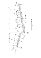
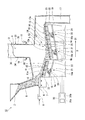
- the stoker furnace of the present embodiment is a stoker furnace for burning incinerators such as refuse, and as shown in FIG. 1, a hopper 2 for temporarily storing incinerators B and an incinerator for burning the incinerators B.
- the feeder 4 continuously extrudes the incinerated material B supplied onto the feed table 7 via the hopper 2 into the incinerator 3.
- the feeder 4 reciprocates on the feed table 7 with a predetermined stroke by the feeder driving device 8.
- the incinerator 3 is provided above the stoker 5 and has a combustion chamber 9 composed of a primary combustion chamber and a secondary combustion chamber.
- a secondary air supply nozzle 10 that supplies secondary air to the combustion chamber 9 is connected to the incinerator 3.
- the stalker 5 is a combustion device in which grate 15 and 16 are arranged in a stepwise manner.
- the incineration material B burns on the stoker 5.
- the direction in which the incinerated material B is transported is referred to as a transport direction D.
- the incinerated material B is transported on the stoker 5 in the transport direction D. 1, 2 and 3, the right side is the downstream side D1 in the transport direction.
- the surface on which the grate 15 or 16 is attached is referred to as an installation surface, and is installed on a horizontal plane with the upstream end (11b, 12b, 13b) of the drying stage 11, the combustion stage 12, or the post-combustion stage 13 as a center.
- the angle formed on the side in the transport direction D formed by the surface is referred to as a stalker inclination angle (installation angle).
- installation angle When the downstream direction D1 of the installation surface in the transport direction is upward from the horizontal plane, the stoker inclination angle is a positive value.
- the stoker inclination angle is a negative value. This will be described here.
- the stoker 5 includes a drying stage 11 for drying the incinerated material B, a combustion stage 12 for incinerating the incinerated material B, and a complete incineration of unburned matter (post-combustion) from the upstream side in the conveying direction of the incinerated material B. )), And a post-combustion stage 13.
- the stoker 5 performs drying, combustion, and post-combustion in the drying stage 11, the combustion stage 12, and the post-combustion stage 13 while sequentially transporting the incinerated material B.
- the stoker furnace 1 supplies the first air box 6a for supplying the primary air blown by the blower (not shown) to the drying stage 11, the second air box 6b for supplying the combustion stage 12, and the post-combustion stage 13.
- the drying stage 11, the combustion stage 12, and the post-combustion stage 13 have a plurality of fixed grate 15 and a plurality of moving grate 16.
- the fixed grate 15 and the moving grate 16 are alternately arranged in the transport direction D.
- the moving grate 16 reciprocates in the transport direction D of the incinerated material B.
- the object B on the stoker 5 is transported and agitated by the reciprocating motion of the moving grate 16. That is, the lower part of the incinerated material B is moved and replaced with the upper part.
- the drying stage 11 receives the incinerated material B pushed out by the feeder 4 and dropped into the incinerator 3, evaporates the moisture of the incinerated material B, and partially decomposes it.
- the combustion stage 12 ignites the incinerated material B dried in the drying stage 11 by the primary air supplied from the second wind box 6b, and burns volatiles and fixed carbon.
- the post-combustion stage 13 burns unburned components such as fixed carbon which have passed through without being burned in the combustion stage 12 until they become completely ash.
- An ash outlet 17 is provided at the outlet of the post-combustion stage 13. The ash is discharged from the incinerator 3 through the ash outlet 17.
- the stoker furnace 1 includes a first driving device 18 a for driving the moving grate 16 of the drying stage 11, a second driving device 18 b for driving the moving grate 16 of the combustion stage 12, and a moving grate 16 of the post-combustion stage 13. And a third driving device 18c for driving the driving device.
- the first driving device 18a, the second driving device 18b, and the third driving device 18c are controlled by the control device 30.
- the driving devices 18a, 18b, 18c are attached to beams 19 provided on the stalker 5.
- Each of the driving devices 18a, 18b, and 18c has a hydraulic cylinder 20 attached to the beam 19, an arm 21 operated by the hydraulic cylinder 20, and a beam 22 connected to a tip of the arm 21.
- the beam 22 and the moving grate 16 are connected via a bracket 23.
- the arm 21 operates by the expansion and contraction of the rod of the hydraulic cylinder 20.
- the beam 22 configured to move along the installation surfaces 11a, 12a, 13a of the stalker 5 moves, and the moving grate 16 connected to the beam 22 is driven.
- the drive devices 18a, 18b, and 18c of the present embodiment use the hydraulic cylinder 20, but the present invention is not limited to this.
- a hydraulic motor, an electric cylinder, a conductive linear motor, or the like can be used.
- the form of the driving devices 18a, 18b, 18c is not limited to the above-described form, and may be any form as long as the movable grate 16 can be reciprocated.
- the beam 22 and the hydraulic cylinder 20 may be directly connected and driven without disposing the arm 21.
- control device 30 sets the driving speed of the moving grate 16 in the drying stage 11, the combustion stage 12, and the post-combustion stage 13 to the same speed or the drying stage 11, the combustion stage 12, And the post-combustion stage 13 can control to different speeds.
- the fixed grate 15 and the moving grate 16 are located on the downstream side in the transport direction with respect to the installation surfaces 11 a, 12 a, and 13 a of the drying stage 11, the combustion stage 12, and the post-combustion stage 13.
- D1 is arranged so as to be inclined upward.
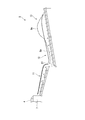
- a part of the moving grate 16 of the drying stage 11 is a grate 16P with projections (the others are normal grate described later).
- the moving grate 16 in the range R1 of 50% to 80% from the downstream side D1 in the conveyance direction of the length in the conveyance direction D of the drying stage 11 is a grate 16P with projections.
- the grate with projection 16 ⁇ / b> P has a plate-shaped grate main body 25 and a triangular protrusion 26 provided at the tip of the grate main body 25.
- the protrusion 26 protrudes upward from the upper surface of the grate main body 25.
- the shape of the projection 26 is not limited to this, and may be, for example, a trapezoidal shape or a round shape.
- the fixed grate 15 in FIG. 3 is a grate having no protrusion on the top surface of the tip, and this shape is called a normal grate.
- the moving grate 16 is a grate with projections 16P.
- the present invention is not limited to this, and both the moving grate 16 and the fixed grate 15 may be grate with projections.
- the range in which the grate with projections 16P is provided is not limited to the above-described range.
- all grate in the drying stage 11 may be the grate with projections 16P.
- all the grate (fixed grate 15 and moving grate 16) in the drying stage 11 may be a normal grate.
- a part of the moving grate 16 in the combustion stage 12 is a grate 16P with projections.
- the moving grate 16 in the range R2 of 50% to 80% from the downstream side in the transport direction is the grate 16P with projections.
- the other moving grate 16 of the combustion stage 12 is a normal grate.
- both the moving grate 16 and the fixed grate 15 may be formed as projection grate 16P, or all grate (the fixed grate 15 and the moving The grate 16) may be a normal grate.
- the moving grate 16 and the fixed grate 15 are all shown as normal grate in FIG. 2, but like the drying stage 11 and the combustion stage 12, the grate with projection 16P is used. May be adopted.
- the drying stage 11 of the stoker 5 of the present embodiment is arranged downward. That is, the installation surface 11a of the drying stage 11 is inclined so that the downstream side D1 in the transport direction becomes lower.
- the stoker inclination angle ⁇ 1 of the drying stage 11 which is an angle between the horizontal plane centered on the upstream end 11b of the drying stage 11 and the transport direction side of the installation surface 11a is ⁇ 15 ° ( ⁇ 15 °). The angle is between ⁇ 25 ° (minus 25 °).
- the combustion stage 12 of the stoker 5 of this embodiment is arranged upward. That is, the installation surface 12a of the combustion stage 12 is inclined such that the downstream side D1 in the transport direction is higher.
- the stoker inclination angle ⁇ 2 of the combustion stage 12 that is the angle between the horizontal plane centered on the upstream end 12b of the combustion stage 12 and the transport direction side of the installation surface 12a is from + 5 ° (plus 5 degrees). The angle is between + 15 ° (plus 15 degrees), preferably between + 8 ° (plus 8 degrees) and + 12 ° (plus 12 degrees).
- the post-combustion stage 13 of the stoker 5 of the present embodiment is arranged upward. That is, the installation surface 13a of the post-combustion stage 13 is inclined such that the downstream side D1 in the transport direction becomes higher.
- the stoker inclination angle ⁇ 3 of the post-combustion stage 13 which is the angle between the horizontal plane around the upstream end 13b of the post-combustion stage 13 and the transport direction side of the installation surface 13a is the same as the stoker inclination angle ⁇ 2 of the combustion stage 12. is there.
- the stoker inclination angle ⁇ 3 of the post-combustion stage 13 which is the angle between the horizontal plane centered on the upstream end 13b of the post-combustion stage 13 and the transport direction side of the installation surface 13a is + 5 ° (+5 degrees).
- a step (fall wall) 27 is formed between the drying stage 11 and the combustion stage 12.
- the downstream end 11c of the drying stage 11 in the transport direction is formed to be vertically higher than the upstream end 12b of the combustion stage 12 in the transport direction.
- the combustion stage 12 and the post-combustion stage 13 are positioned such that the downstream end 12c of the combustion stage 12 in the transport direction and the upstream end 13b of the post-combustion stage 13 in the transport direction are at the same height. Is formed. Accordingly, the downstream end 13c of the post-combustion stage 13 in the transport direction is disposed above the downstream end 12c of the combustion stage 12 in the transport direction in the vertical direction.
- the function of the drying stage 11 is to efficiently dry moisture in the incinerator B by radiant heat from the flame above the incinerator B in the combustion stage 12 and sensible heat of the primary air from below the grate.
- the radiant heat from the flame has a higher contribution to the drying than the sensible heat of the primary air, and the upper layer of the incinerated material B is more likely to be dried.
- the drying speed is improved by moving the lower part of the incineration object B upward by the stirring operation by the grate and replacing it with the upper part.
- the absolute value of the stoker inclination angle is larger than the angle of repose of the incinerated material B, it collapses under its own weight, and a layer of the incinerated material B is not formed.
- the absolute value of the stoker inclination angle is made smaller than the angle of repose of the incineration object B, the stoker is realized, but the movement of the incineration object B by gravity (movement by its own weight) decreases.
- gravity acts in a direction to push the incinerated material B back from the transport direction. If the transport amount of the incinerated material B by the stalker 5 is smaller than the amount of the incinerated material B, the transport limit is reached and the processing becomes impossible.
- the optimum stoker inclination angle differs depending on the amount of the incinerator B to be charged and the water content of the incinerator B.
- description will be made assuming that the amount of the incinerator B to be charged is large and the moisture content is high (the amount of water is large), and the case where the load of the incinerator to be charged is large. Conversely, when the amount of the incinerator B to be charged is small and the moisture content is low, the load of the incinerator to be charged is small.
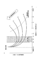
- the horizontal axis represents the stoker inclination angle of the drying stage 11
- the vertical axis represents the required stoker length of the drying stage 11
- the input incinerator load is the smallest in order from (1) when the input incinerator load is the highest.
- the required stoker length is a distance at which 95% of the moisture of the to-be-incinerated material B is dried.
- the “angle of repose” on the horizontal axis indicates the angle of repose of the incinerated material B.
- the stoker inclination angle of ⁇ 30 ° is the limit for forming the layer of the incineration material B.
- the required stoker length decreases as the stoker inclination angle decreases, but when the stoker inclination angle turns to a positive value, the required stoker length gradually increases. This is because, when the stoker inclination angle becomes a positive value, the installation surface becomes upward, and the transport speed becomes slow. As a result, the layer of the incinerator B becomes thicker, and the incinerator B in the lower layer hardly dries. Because it becomes.
- the incinerated material B is in any property and quantity.
- the optimum stoker inclination angle of the drying stage 11 that can properly process the stoker and minimize the stoker length is ⁇ 15 ° ( ⁇ 15 °) corresponding to the stoker length near the lowest point of the curve of (1). ) To ⁇ 25 ° (minus 25 °) is within an appropriate range. Then, the optimum value is ⁇ 20 ° ( ⁇ 20 °).
- the stoker inclination angle of the drying stage 11 is in the appropriate range as described above, the stoker inclination angle of the combustion stage 12 is between + 8 ° (plus 8 degrees) to + 12 ° (plus 12 degrees). The reason why the angle is suitable will be described.
- the function of the combustion stage 12 is to maintain the temperature of the layer of the incinerator B by radiant heat from the flame and self-combustion heat, to promote generation of combustible gas by pyrolysis of volatile matter, and to burn fixed carbon remaining after pyrolysis. Is what you do.
- the required stoker length of the combustion stage 12 is determined by the time required for burning the fixed carbon.
- FIG. 5 shows that when the stoker inclination angle of the drying stage 11 is within the appropriate range as described above, the horizontal axis is the stoker inclination angle of the combustion stage, the vertical axis is the required stoker length of the combustion stage, and The relationship between the stoker inclination angle of the combustion stage and the required stoker length of the combustion stage is plotted in order from the case where the load is the largest (1) to the case where the load of the incineration material is the smallest (4).
- the required stoker length of the combustion stage is a distance at which 95% of the combustible component volatilizes or burns.
- the stoker inclination angle of ⁇ 30 ° is the limit for forming the layer of the incineration material B.
- the required stoker length decreases as the angle becomes gentler.
- the appropriate range of the stoker inclination angle can be a range surrounded by a dashed line shown in FIG.
- the stoker inclination angle in the drying stage 11 is within an appropriate range, so that the reduction of the moisture content and the volume of the waste are promoted. For this reason, for example, even if the load in the drying stage 11 corresponds to (1), the load changes in the combustion stage 12 to those corresponding to (3) and (4). Stalker inclination angle can be adopted. That is, since the combustion stage can be directed upward, the residence time required for burning the fixed carbon can be secured, and the stoker length can be further reduced.
- FIG. 6 shows the case where the horizontal axis represents the stoker inclination angle of the combustion stage 12 and the vertical axis represents the stoker length required for both the drying stage 11 and the combustion stage 12, and the load of the incineration material B to be introduced is the largest (1)
- the plot of the relationship between the stoker inclination angle of the combustion stage 12 and the stoker length required in both the drying stage 11 and the combustion stage 12 until the load on the incinerator B to be introduced is the smallest (4). It is.
- the stoker inclination angle of the drying stage 11 is set to an optimum value of ⁇ 20 ° ( ⁇ 20 °).
- the appropriate range of the stoker inclination angle of the combustion stage 12 is approximately an angle between + 5 ° (+5 degrees) to + 15 ° (+15 degrees), more specifically, It can be seen that the angle is between + 8 ° (plus 8 degrees) and + 12 ° (plus 12 degrees).
- the stoker inclination angle of the drying stage 11 is the optimum value of ⁇ 20 ° ( ⁇ 20 degrees)
- the optimum value of the stoker inclination angle of the combustion stage 12 is + 10 ° (+10 degrees).
- the required stoker lengths of the drying stage 11 and the combustion stage 12 can be as short as possible by setting the respective stoker inclination angles within an appropriate range, particularly an optimum value.
- the burn-off point P is a point at which the burning of the incinerated material B on the stoker 5 with the flame is substantially completed.
- the driving speed (moving speed) of the moving grate 16 in each stage is adjusted according to the burn-off point P of the incineration material B. Has the ability to change.
- the target burn-off point Pt which is an ideal burn-off point, is set downstream from the center of the combustion stage 12 when viewed in the transport direction D.
- the target burn-off point Pt is set on the combustion stage 12. If the position of the burn-off point P is on the upstream side in the transport direction from the target burn-off point Pt, the length of the layer of the incinerated material B in the transport direction D is short, and there is a possibility that combustion may not be efficient.
- the length of the layer of the incinerated material B in the transport direction D is long, and there is a possibility that the incinerated material B may remain unburned. is there.
- the thermocouple 31 which is a device for detecting the burn-off point, is installed on the surface of the fixed grate 15 or the movable grate 16 near the target burn-off point Pt among the grate of the combustion stage 12.
- the thermocouple 31 measures the temperature of the grate that fluctuates when the incinerated material B burns on the stoker 5. The measured temperature becomes a detection signal corresponding to the position of the burn-off point P of the incineration material B.
- the control device 30 estimates the burn-off point estimator 30a and the burn-off point estimator 30a to estimate the position of the burn-off point P corresponding to the grate temperature T (detection signal) measured by the thermocouple 31.
- a drive control unit 30b that controls the drives 18a, 18b, 18c based on the position of the burn-off point P.
- the inventors have found that there is a correlation between the grate temperature T of the combustion stage 12 and the position of the burn-off point P. For example, when the target burn-off point Pt as shown in FIG. 2 is set, when the grate temperature T is T1 ° C., the burn-out point P matches the target burn-off point Pt, and the grate temperature T becomes T1 ° C. If it is lower, the burn-out point P is located upstream of the target burn-off point Pt in the transport direction, and if the grate temperature T is higher than T1 ° C., the burn-out point P is downstream of the target burn-off point Pt in the transport direction. It has been found that it can be determined that it is located on the side.
- the present inventors set the driving speed of the moving grate 16 of the post-combustion stage 13 to be lower than the driving speed of the moving grate 16 of the combustion stage 12, thereby moving the layer of the incineration B closer to the combustion stage 12 side. It has been found that it can be deposited. That is, it was found that the layer of the incineration object B remained on the combustion stage 12 side with respect to the post-combustion stage 13 by reducing the driving speed of the moving grate 16 in the post-combustion stage 13.
- the burn-off point estimating unit 30a estimates the position of the burn-off point P based on the grate temperature T of the combustion stage 12 measured by the thermocouple 31.
- the burn-off point P matches the target burn-off point Pt, and when the grate temperature T is lower than T1 ° C.,
- the burn-off point P is located downstream of the target burn-off point Pt in the transport direction. judge.
- the control device 30 drives the moving grate 16 of each of the drying stage 11, the combustion stage 12, and the post-combustion stage 13 at a predetermined driving speed (predetermined speed).
- the predetermined speed of the moving grate 16 in the drying stage 11 is the first driving speed V1
- the predetermined speed of the moving grate 16 in the combustion stage 12 is the second driving speed V2
- the predetermined speed of the moving grate 16 in the post-combustion stage 13 is the first speed.
- V3 V3 or V1 ⁇ V2 ⁇ V3 depending on the properties of the incinerated material B.
- V1 ⁇ V2 ⁇ V3 is often set.
- V2 is a driving speed that makes one round trip in approximately 100 seconds.
- the driving speed is set according to the property of the incinerated material B, and thus this speed is only an example and is not limited to this.
- the drive control unit 30b of the control device 30 determines whether or not the moving stage of the combustion stage 12 is moving when the burn-off point P is at the same position as the target burn-off point Pt or is located upstream of the target burn-off point Pt in the transport direction.
- the second drive device 18b and the third drive device 18c are controlled so as not to change the drive speed of the grate 16 and the moving grate 16 of the post-combustion stage 13. Accordingly, the moving grate 16 of the combustion stage 12 is driven while maintaining the second drive speed V2 which is a predetermined speed, and the moving grate 16 of the post-combustion stage 13 is driven while maintaining the third drive speed V3 which is a predetermined speed. . That is, the moving grate 16 of the combustion stage 12 and the post-combustion stage 13 continue to be driven at the same drive speed as before.
- the drive control unit 30b determines that the driving speed of the moving grate 16 of the post-combustion stage 13 is The second driving device 18b and the third driving device 18c are controlled to drive at a driving speed lower than the driving speed of the second driving device 18b.
- the drive control unit 30b For example, the third driving device 18c is controlled so that the driving speed of the moving grate 16 in the post-combustion stage 13 is further reduced than V3. In other words, the drive control unit 30b controls the drive speed of the moving grate 16 in the post-combustion stage 13 to be lower than before.
- the driving speed of the moving grate 16 in the post-combustion stage 13 can be 30% to 80% of the driving speed of the moving grate 16 in the combustion stage 12.
- the simulation showed that the layer of the incinerated material B was deposited as indicated by the solid line Ba. Since the layer of the incineration material B is formed as shown by the solid line Ba, the agitation is effectively performed by the grate with projections 16P in the combustion stage 12, and the time for holding the incineration material B on the combustion stage 12 Not only to earn money, but also to result in effective combustion. Therefore, the unburned residue of the incinerated material B discharged from the post-combustion stage 13 can be reduced.
- the drying stage 11 since the drying stage 11 is inclined downward, the incineration object B of any property can be transported to the combustion stage 12 without any delay, and the combustion stage 12 Since the post-combustion stage 13 is inclined upward, the incinerated material B is sufficiently burned and conveyed without easily sliding down or rolling down the downstream of the combustion stage 12.
- the incinerated material B having a slippery material or a shape that easily rolls the material is conveyed to the combustion stage 12 early by rolling on the drying stage 11, so that the drying stage 11 may not be sufficiently dried.
- the combustion stage 12 and the post-combustion stage 13 are inclined upward, the incineration material B that has rolled down the drying stage 11 does not further roll down the combustion stage 12 and the post-combustion stage 13.
- always dry and incinerated since the incinerated material B having a high moisture content is conveyed to the combustion stage 12 while being dried without staying in the drying stage 11, it is also necessarily sufficiently incinerated in the combustion stage 12. Thereby, the incinerated material B can be continuously charged irrespective of the properties of the incinerated material B, and the unburned material of the incinerated material B can be eliminated.
- the incinerated material B that has rolled down the drying stage 11 has a strong momentum and passes through the combustion stage 12 at that moment, it is at least stopped in the post-combustion stage 13 and discharged from the post-combustion stage 13. Absent. Since the post-combustion stage 13 and the combustion stage 12 are continuously connected without any level difference, even if the incinerated material B that is not sufficiently burned to the post-combustion stage 13 rolls and advances, for example, the self-weight is reduced. To return to the combustion stage 12 to perform combustion. That is, it is possible to minimize the discharge of the incompletely burned incinerator B.
- the driving speed of the moving grate 16 of the post-combustion stage 13 should be lower than the driving speed of the moving grate 16 of the combustion stage 12.
- the layer of the incineration material B can be retained on the combustion stage 12 side.
- the thickness of the layer of the incineration material B on the combustion stage 12 is maintained, and the grate of the combustion stage 12 can be protected.
- the grate 15 and 16 can be protected by the layer of the incinerated material B, and the processing can be performed even when a processing object larger than expected is thrown in.
- An object can be transported in the transport direction D.
- thermocouple 31 as a burn-off point detecting device for obtaining a detection signal corresponding to the burn-off point P, the position of the burn-off point P can be set with a cheaper configuration.
- the position of the burn-off point P corresponds to the grate temperature T measured by the thermocouple 31 disposed on the grate of the combustion stage 12, but is not limited thereto.
- a configuration may be adopted in which the temperature change (change speed) of the grate temperature T measured by the thermocouple 31 is monitored, and the position of the burn-off point P is estimated based on the temperature change of the grate temperature T.
- the thermocouple 31 is provided in the combustion stage 12.
- the present invention is not limited to this, and the thermocouple may be provided in at least one of the combustion stage 12 and the post-combustion stage 13. When the thermocouple 31 is installed in the combustion stage 12, the downstream side of the combustion stage 12 is desirable, and when the thermocouple 31 is installed in the post-combustion stage 13, the upstream side of the post-combustion stage 13 is desirable.
- the burn-off point detection device may be configured to include a plurality of thermocouples. That is, the thermocouples may be arranged, for example, on the upstream side of the combustion stage 12, the downstream side of the combustion stage 12, the upstream side of the post-combustion stage 13, and the downstream side of the post-combustion stage 13, respectively.
- the number of thermocouples is not limited to this, and can be appropriately changed according to the size of the stoker 5 and the cost.
- a plurality of thermocouples may be arranged in the depth direction of the paper of FIG.
- the stoker furnace of the present embodiment measures the grate temperature Td of the drying stage 11 and outputs a temperature signal corresponding thereto to the control device 30B (drying stage temperature measurement device).
- the apparatus includes, for example, a drying stage thermocouple 32) and measures the pressure PR1 in the first wind box 6a disposed below the drying stage 11 and outputs a corresponding first pressure signal to the control device 30B.
- a second pressure measurement which measures the pressure PR2 in the first pressure measuring device 33a and the second wind box 6b arranged below the combustion stage 12 and outputs a corresponding second pressure signal to the control device 30B.
- the drying stage thermocouple 32 is preferably installed on the surface of the fixed grate 15 or the moving grate 16 of the drying stage 11 downstream of the center of the drying stage 11 when viewed in the transport direction D.
- the control device 30B of the present embodiment adds the driving speed of the moving grate 16 of the combustion stage 12 and the driving speed of the moving grate 16 of the post-combustion stage 13 based on the grate temperatures T and Td and the pressures PR1 and PR2. The driving speed of the moving grate 16 of the drying stage 11 is controlled.
- the control device 30B of the present embodiment sets a threshold (first threshold corresponding to the first wind box 6a and second threshold corresponding to the second wind box 6b) for the pressure in the wind box.
- the threshold value is set based on the thickness of the incinerated material B deposited on the stoker on the wind box. Note that the first threshold value and the second threshold value may be set to the same value, or may be set to different values depending on the properties of the incinerated material B. If the pressure in the wind box is equal to or larger than the threshold, the control device 30 determines that the thickness of the layer of the incineration object B is excessive.
- the pressure PR2 in the second wind box 6b is lower than the threshold value (second threshold value)
- the threshold value (first threshold value) it is determined that the layer of the incineration object B on the combustion stage 12 is thin and the processing capability of the combustion stage 12 has a margin. can do.
- the pressure PR1 of the first wind box 6a is equal to or higher than the threshold value (first threshold value) and the grate temperature Td of the drying stage 11 is equal to or higher than a predetermined temperature (third threshold value), Is thick, and it can be determined that the incineration B is being burned in the drying stage 11.
- the control device 30B first performs control for driving the moving grate of the drying stage 11 at the predetermined speed V1. Then, the control device 30B performs the same control as that of the stoker furnace 1 of the first embodiment, and the pressure PR1 in the first wind box 6a is equal to or more than a threshold (first threshold) and the pressure PR1 in the second wind box 6b.
- first threshold a threshold
- second threshold value the threshold value
- third threshold value a predetermined temperature
- Control is performed to make the speed higher than the predetermined speed V1.
- the control device 30 determines that the pressure PR1 in the first wind box 6a is less than the threshold value (first threshold value), the pressure PR2 in the second wind box 6b is not less than the threshold value (second threshold value), and the drying stage 11
- the grate temperature Td is lower than a predetermined temperature (third threshold value)
- control is performed to make the driving speed of the moving grate 16 of the drying stage 11 slower than the predetermined speed V1.
- the control device 30B performs control by comparing the pressures PR1 and PR2 with the corresponding thresholds, but is not limited thereto.
- the control device 30B may be configured to monitor and control a pressure change (change speed) of the pressures PR1 and PR2.
- the control device 30B may be configured to monitor and control a temperature change (change speed) of the grate temperature Td of the drying stage 11.
- the first pressure signal is a signal corresponding to a pressure change of the pressure PR1
- the second pressure signal is a signal corresponding to a pressure change of the pressure PR2
- the temperature signal is a signal corresponding to a temperature change of the grate temperature Td.
- the first threshold value, the second threshold value, and the third threshold value may be set in correspondence with these signals.
- the stoker furnace 1 ⁇ / b> C of the present embodiment includes, as a burn-off point detection device, an imaging device 34 installed above the post-combustion stage 13, specifically, on the ceiling of the furnace.
- the imaging device 34 is a camera or a sensor that can detect a temperature distribution.
- the temperature distribution detected by the imaging device 34 downstream of the combustion stage 12 or upstream of the post-combustion stage 13 is a detection signal corresponding to the position of the burn-off point P of the incineration object B.
- the burn-off point estimation unit 30a of the control device estimates the position of the burn-off point P based on the temperature distribution detected by the imaging device 34.
- the driving device control unit 30b sets the drive grate 16 after the moving grate 16 of the combustion stage 12
- the second driving device 18b and the third driving device 18c are controlled such that the moving grate 16 of the combustion stage 13 is driven at the same driving speed.
- the drive control unit 30b determines that the driving speed of the moving grate 16 in the post-combustion stage 13 is lower than in the first embodiment.
- the second driving device 18b and the third driving device 18c are controlled so that the driving speed is lower than the driving speed of the moving grate 16 of the combustion stage 12.
- the position of the burn-off point P can be more accurately estimated.
- the embodiments of the present invention have been described in detail with reference to the drawings.
- the specific configuration is not limited to the embodiments, and includes a design change or the like without departing from the gist of the present invention.
- tip of the grate 15,16 is arrange
- tip of the grate 15,16 of the drying stage 11 May be arranged to face the upstream side in the transport direction.
- thermocouple and the imaging device may be used as the burn-off point detection device, but also the position of the burn-off point P may be estimated using both the thermocouple and the imaging device.
- the first embodiment or the second embodiment is combined with the third embodiment may be adopted.
Landscapes
- Engineering & Computer Science (AREA)
- Mechanical Engineering (AREA)
- General Engineering & Computer Science (AREA)
- Chemical & Material Sciences (AREA)
- Combustion & Propulsion (AREA)
- Incineration Of Waste (AREA)
Abstract
Priority Applications (10)
| Application Number | Priority Date | Filing Date | Title |
|---|---|---|---|
| KR1020217008829A KR102318973B1 (ko) | 2018-08-30 | 2018-10-26 | 스토커로 |
| SG11202003129PA SG11202003129PA (en) | 2018-08-30 | 2018-10-26 | Stoker furnace |
| EP18931954.4A EP3845806B1 (fr) | 2018-08-30 | 2018-10-26 | Four à foyer mécanique |
| RU2020114364A RU2731612C1 (ru) | 2018-08-30 | 2018-10-26 | Стокерная печь |
| DK18931954.4T DK3845806T3 (da) | 2018-08-30 | 2018-10-26 | Stoker-ovn |
| CN201880002956.1A CN111133251B (zh) | 2018-08-30 | 2018-10-26 | 机械炉排炉 |
| MYPI2020001791A MY199411A (en) | 2018-08-30 | 2018-10-26 | Stoker furnace |
| BR112020008004-7A BR112020008004B1 (pt) | 2018-08-30 | 2018-10-26 | forno carregador |
| PL18931954.4T PL3845806T3 (pl) | 2018-08-30 | 2018-10-26 | Palenisko rusztowe |
| PH12020550227A PH12020550227A1 (en) | 2018-08-30 | 2020-04-06 | Stoker furnace |
Applications Claiming Priority (2)
| Application Number | Priority Date | Filing Date | Title |
|---|---|---|---|
| JP2018161817A JP6450987B1 (ja) | 2018-08-30 | 2018-08-30 | ストーカ炉 |
| JP2018-161817 | 2018-08-30 |
Publications (1)
| Publication Number | Publication Date |
|---|---|
| WO2020044577A1 true WO2020044577A1 (fr) | 2020-03-05 |
Family
ID=65020380
Family Applications (1)
| Application Number | Title | Priority Date | Filing Date |
|---|---|---|---|
| PCT/JP2018/039867 Ceased WO2020044577A1 (fr) | 2018-08-30 | 2018-10-26 | Four à foyer mécanique |
Country Status (13)
| Country | Link |
|---|---|
| EP (1) | EP3845806B1 (fr) |
| JP (1) | JP6450987B1 (fr) |
| KR (1) | KR102318973B1 (fr) |
| CN (1) | CN111133251B (fr) |
| BR (1) | BR112020008004B1 (fr) |
| DK (1) | DK3845806T3 (fr) |
| MY (1) | MY199411A (fr) |
| PH (1) | PH12020550227A1 (fr) |
| PL (1) | PL3845806T3 (fr) |
| RU (1) | RU2731612C1 (fr) |
| SG (1) | SG11202003129PA (fr) |
| TW (1) | TWI697644B (fr) |
| WO (1) | WO2020044577A1 (fr) |
Families Citing this family (6)
| Publication number | Priority date | Publication date | Assignee | Title |
|---|---|---|---|---|
| KR102475048B1 (ko) * | 2020-12-22 | 2022-12-07 | 지엔원에너지(주) | 스토커 타입의 소각로 및 그 제어방법 |
| KR102574488B1 (ko) * | 2021-03-23 | 2023-09-04 | 재단법인 포항산업과학연구원 | 연소 안정화를 위한 소각로의 운전 제어 장치 및 방법 |
| CN114060826B (zh) * | 2021-11-23 | 2024-05-28 | 浦湘生物能源股份有限公司 | 一种焚烧炉自动焚烧控制方法及控制系统 |
| DE102022107219A1 (de) | 2022-03-28 | 2023-09-28 | Hitachi Zosen Inova Steinmüller GmbH | Verfahren zum Betreiben eines Schubrosts und Schubrost |
| CN116293703A (zh) * | 2023-04-28 | 2023-06-23 | 重庆滨南生态科技有限公司 | 多炉膛顺逆推组合分级气化燃烧炉 |
| WO2026063808A1 (fr) * | 2024-09-20 | 2026-03-26 | Tautan Nicolae Valer | Chaudières à vapeur ctdl sur combustible solide mélangé ayant une humidité élevée > 40 % avec chambre de combustion au gaz naturel (gn) et/au gn + combustible h2 écologique |
Citations (12)
| Publication number | Priority date | Publication date | Assignee | Title |
|---|---|---|---|---|
| JPS5712053B2 (fr) | 1973-07-28 | 1982-03-09 | ||
| JPS57127129U (fr) | 1973-10-08 | 1982-08-07 | ||
| JPS5986814A (ja) | 1982-11-10 | 1984-05-19 | Sanki Eng Co Ltd | ごみ焼却炉における自動燃焼制御方法 |
| JPH0328618A (ja) | 1989-02-23 | 1991-02-06 | Ebara Infilco Co Ltd | 焼却炉の燃焼制御方法 |
| JPH05141640A (ja) * | 1991-11-19 | 1993-06-08 | Kubota Corp | 焼却炉の燃焼制御装置 |
| JPH06265125A (ja) | 1993-03-15 | 1994-09-20 | Unitika Ltd | ごみ焼却炉の火格子 |
| JPH0684140U (ja) | 1993-04-23 | 1994-12-02 | 株式会社クボタ | ゴミ焼却炉 |
| JPH06341628A (ja) * | 1993-06-03 | 1994-12-13 | Kubota Corp | ゴミ焼却炉 |
| JPH1137436A (ja) * | 1997-07-16 | 1999-02-12 | Sumitomo Heavy Ind Ltd | 水平ストーカ式ごみ焼却炉のごみ送り制御方式 |
| JP2005214513A (ja) * | 2004-01-29 | 2005-08-11 | Takuma Co Ltd | ストーカ型ごみ焼却炉によるごみの燃焼方法 |
| JP6397107B1 (ja) * | 2017-10-17 | 2018-09-26 | 三菱重工環境・化学エンジニアリング株式会社 | ごみ等の被焼却物燃焼用ストーカ炉 |
| JP2018161817A (ja) | 2017-03-27 | 2018-10-18 | セイコーエプソン株式会社 | 記録装置 |
Family Cites Families (8)
| Publication number | Priority date | Publication date | Assignee | Title |
|---|---|---|---|---|
| SU855345A1 (ru) * | 1979-08-03 | 1981-08-15 | Ордена Трудового Красного Знамени Академия Коммунального Хозяйства Им.К.Д.Памфилова | Мусоросжигательна печь |
| SU1441136A1 (ru) * | 1986-11-24 | 1988-11-30 | Предприятие П/Я А-3513 | Топка дл сжигани твердых бытовых и промышленных отходов |
| JPH08285241A (ja) * | 1995-04-11 | 1996-11-01 | Kubota Corp | ゴミ焼却炉 |
| JP3669779B2 (ja) * | 1996-08-02 | 2005-07-13 | 株式会社クボタ | ゴミ焼却炉の燃焼制御装置 |
| TW200829835A (en) * | 2006-09-04 | 2008-07-16 | Mitsubishi Heavy Ind Ltd | Stoker type incinerator and its combustion control method |
| JP5013808B2 (ja) * | 2006-10-13 | 2012-08-29 | 三菱重工環境・化学エンジニアリング株式会社 | ストーカ式焼却炉の燃焼制御装置 |
| CN101101122B (zh) * | 2007-08-01 | 2010-10-13 | 重庆科技学院 | 复合式炉排焚烧炉一次风供风装置 |
| CN201096345Y (zh) * | 2007-08-02 | 2008-08-06 | 重庆科技学院 | 多列分段驱动复合式垃圾焚烧炉 |
-
2018
- 2018-08-30 JP JP2018161817A patent/JP6450987B1/ja active Active
- 2018-10-26 DK DK18931954.4T patent/DK3845806T3/da active
- 2018-10-26 CN CN201880002956.1A patent/CN111133251B/zh active Active
- 2018-10-26 MY MYPI2020001791A patent/MY199411A/en unknown
- 2018-10-26 RU RU2020114364A patent/RU2731612C1/ru active
- 2018-10-26 PL PL18931954.4T patent/PL3845806T3/pl unknown
- 2018-10-26 KR KR1020217008829A patent/KR102318973B1/ko active Active
- 2018-10-26 BR BR112020008004-7A patent/BR112020008004B1/pt active IP Right Grant
- 2018-10-26 WO PCT/JP2018/039867 patent/WO2020044577A1/fr not_active Ceased
- 2018-10-26 SG SG11202003129PA patent/SG11202003129PA/en unknown
- 2018-10-26 EP EP18931954.4A patent/EP3845806B1/fr active Active
-
2019
- 2019-06-28 TW TW108122842A patent/TWI697644B/zh active
-
2020
- 2020-04-06 PH PH12020550227A patent/PH12020550227A1/en unknown
Patent Citations (12)
| Publication number | Priority date | Publication date | Assignee | Title |
|---|---|---|---|---|
| JPS5712053B2 (fr) | 1973-07-28 | 1982-03-09 | ||
| JPS57127129U (fr) | 1973-10-08 | 1982-08-07 | ||
| JPS5986814A (ja) | 1982-11-10 | 1984-05-19 | Sanki Eng Co Ltd | ごみ焼却炉における自動燃焼制御方法 |
| JPH0328618A (ja) | 1989-02-23 | 1991-02-06 | Ebara Infilco Co Ltd | 焼却炉の燃焼制御方法 |
| JPH05141640A (ja) * | 1991-11-19 | 1993-06-08 | Kubota Corp | 焼却炉の燃焼制御装置 |
| JPH06265125A (ja) | 1993-03-15 | 1994-09-20 | Unitika Ltd | ごみ焼却炉の火格子 |
| JPH0684140U (ja) | 1993-04-23 | 1994-12-02 | 株式会社クボタ | ゴミ焼却炉 |
| JPH06341628A (ja) * | 1993-06-03 | 1994-12-13 | Kubota Corp | ゴミ焼却炉 |
| JPH1137436A (ja) * | 1997-07-16 | 1999-02-12 | Sumitomo Heavy Ind Ltd | 水平ストーカ式ごみ焼却炉のごみ送り制御方式 |
| JP2005214513A (ja) * | 2004-01-29 | 2005-08-11 | Takuma Co Ltd | ストーカ型ごみ焼却炉によるごみの燃焼方法 |
| JP2018161817A (ja) | 2017-03-27 | 2018-10-18 | セイコーエプソン株式会社 | 記録装置 |
| JP6397107B1 (ja) * | 2017-10-17 | 2018-09-26 | 三菱重工環境・化学エンジニアリング株式会社 | ごみ等の被焼却物燃焼用ストーカ炉 |
Non-Patent Citations (1)
| Title |
|---|
| See also references of EP3845806A4 |
Also Published As
| Publication number | Publication date |
|---|---|
| PH12020550227A1 (en) | 2021-02-08 |
| BR112020008004B1 (pt) | 2021-02-17 |
| RU2731612C1 (ru) | 2020-09-07 |
| PL3845806T3 (pl) | 2024-10-07 |
| CN111133251B (zh) | 2021-01-12 |
| DK3845806T3 (da) | 2024-09-30 |
| EP3845806A4 (fr) | 2022-06-08 |
| TWI697644B (zh) | 2020-07-01 |
| KR102318973B1 (ko) | 2021-10-28 |
| JP2020034232A (ja) | 2020-03-05 |
| BR112020008004A2 (pt) | 2020-08-18 |
| EP3845806A1 (fr) | 2021-07-07 |
| SG11202003129PA (en) | 2020-07-29 |
| MY199411A (en) | 2023-10-26 |
| KR20210040158A (ko) | 2021-04-12 |
| EP3845806B1 (fr) | 2024-07-17 |
| CN111133251A (zh) | 2020-05-08 |
| TW202009419A (zh) | 2020-03-01 |
| JP6450987B1 (ja) | 2019-01-16 |
Similar Documents
| Publication | Publication Date | Title |
|---|---|---|
| JP6450987B1 (ja) | ストーカ炉 | |
| EP3699490B1 (fr) | Four de chauffeur pour brûler un matériau à incinérer | |
| EP3845805B1 (fr) | Four à chargeur | |
| EP3734155B1 (fr) | Dispositif d'étanchéité de four à chargement mécanique et four à chargement mécanique | |
| JP3219379U (ja) | ストーカ炉 | |
| JP6481231B1 (ja) | ストーカ炉 | |
| JP2013178008A (ja) | 焼却設備及び焼却設備の制御方法 | |
| JP2019199991A (ja) | 廃棄物焼却炉及び廃棄物焼却方法 |
Legal Events
| Date | Code | Title | Description |
|---|---|---|---|
| 121 | Ep: the epo has been informed by wipo that ep was designated in this application |
Ref document number: 18931954 Country of ref document: EP Kind code of ref document: A1 |
|
| REG | Reference to national code |
Ref country code: BR Ref legal event code: B01A Ref document number: 112020008004 Country of ref document: BR |
|
| ENP | Entry into the national phase |
Ref document number: 112020008004 Country of ref document: BR Kind code of ref document: A2 Effective date: 20200422 |
|
| NENP | Non-entry into the national phase |
Ref country code: DE |
|
| ENP | Entry into the national phase |
Ref document number: 2018931954 Country of ref document: EP Effective date: 20210330 |