WO2020049920A1 - Commutateur d'image médicale - Google Patents
Commutateur d'image médicale Download PDFInfo
- Publication number
- WO2020049920A1 WO2020049920A1 PCT/JP2019/030481 JP2019030481W WO2020049920A1 WO 2020049920 A1 WO2020049920 A1 WO 2020049920A1 JP 2019030481 W JP2019030481 W JP 2019030481W WO 2020049920 A1 WO2020049920 A1 WO 2020049920A1
- Authority
- WO
- WIPO (PCT)
- Prior art keywords
- input
- output
- frame
- displayed
- operation screen
- Prior art date
- Legal status (The legal status is an assumption and is not a legal conclusion. Google has not performed a legal analysis and makes no representation as to the accuracy of the status listed.)
- Ceased
Links
Images






Classifications
-
- H—ELECTRICITY
- H04—ELECTRIC COMMUNICATION TECHNIQUE
- H04N—PICTORIAL COMMUNICATION, e.g. TELEVISION
- H04N7/00—Television systems
- H04N7/18—Closed-circuit television [CCTV] systems, i.e. systems in which the video signal is not broadcast
- H04N7/181—Closed-circuit television [CCTV] systems, i.e. systems in which the video signal is not broadcast for receiving images from a plurality of remote sources
-
- A—HUMAN NECESSITIES
- A61—MEDICAL OR VETERINARY SCIENCE; HYGIENE
- A61B—DIAGNOSIS; SURGERY; IDENTIFICATION
- A61B1/00—Instruments for performing medical examinations of the interior of cavities or tubes of the body by visual or photographical inspection, e.g. endoscopes; Illuminating arrangements therefor
-
- A—HUMAN NECESSITIES
- A61—MEDICAL OR VETERINARY SCIENCE; HYGIENE
- A61B—DIAGNOSIS; SURGERY; IDENTIFICATION
- A61B1/00—Instruments for performing medical examinations of the interior of cavities or tubes of the body by visual or photographical inspection, e.g. endoscopes; Illuminating arrangements therefor
- A61B1/04—Instruments for performing medical examinations of the interior of cavities or tubes of the body by visual or photographical inspection, e.g. endoscopes; Illuminating arrangements therefor combined with photographic or television appliances
- A61B1/045—Control thereof
-
- A—HUMAN NECESSITIES
- A61—MEDICAL OR VETERINARY SCIENCE; HYGIENE
- A61B—DIAGNOSIS; SURGERY; IDENTIFICATION
- A61B90/00—Instruments, implements or accessories specially adapted for surgery or diagnosis and not covered by any of the groups A61B1/00 - A61B50/00, e.g. for luxation treatment or for protecting wound edges
-
- A—HUMAN NECESSITIES
- A61—MEDICAL OR VETERINARY SCIENCE; HYGIENE
- A61B—DIAGNOSIS; SURGERY; IDENTIFICATION
- A61B90/00—Instruments, implements or accessories specially adapted for surgery or diagnosis and not covered by any of the groups A61B1/00 - A61B50/00, e.g. for luxation treatment or for protecting wound edges
- A61B90/36—Image-producing devices or illumination devices not otherwise provided for
- A61B90/37—Surgical systems with images on a monitor during operation
-
- G—PHYSICS
- G02—OPTICS
- G02B—OPTICAL ELEMENTS, SYSTEMS OR APPARATUS
- G02B23/00—Telescopes, e.g. binoculars; Periscopes; Instruments for viewing the inside of hollow bodies; Viewfinders; Optical aiming or sighting devices
- G02B23/24—Instruments or systems for viewing the inside of hollow bodies, e.g. fibrescopes
-
- G—PHYSICS
- G06—COMPUTING OR CALCULATING; COUNTING
- G06F—ELECTRIC DIGITAL DATA PROCESSING
- G06F3/00—Input arrangements for transferring data to be processed into a form capable of being handled by the computer; Output arrangements for transferring data from processing unit to output unit, e.g. interface arrangements
- G06F3/01—Input arrangements or combined input and output arrangements for interaction between user and computer
- G06F3/048—Interaction techniques based on graphical user interfaces [GUI]
- G06F3/0481—Interaction techniques based on graphical user interfaces [GUI] based on specific properties of the displayed interaction object or a metaphor-based environment, e.g. interaction with desktop elements like windows or icons, or assisted by a cursor's changing behaviour or appearance
- G06F3/0482—Interaction with lists of selectable items, e.g. menus
-
- G—PHYSICS
- G06—COMPUTING OR CALCULATING; COUNTING
- G06F—ELECTRIC DIGITAL DATA PROCESSING
- G06F3/00—Input arrangements for transferring data to be processed into a form capable of being handled by the computer; Output arrangements for transferring data from processing unit to output unit, e.g. interface arrangements
- G06F3/01—Input arrangements or combined input and output arrangements for interaction between user and computer
- G06F3/048—Interaction techniques based on graphical user interfaces [GUI]
- G06F3/0484—Interaction techniques based on graphical user interfaces [GUI] for the control of specific functions or operations, e.g. selecting or manipulating an object, an image or a displayed text element, setting a parameter value or selecting a range
-
- H—ELECTRICITY
- H04—ELECTRIC COMMUNICATION TECHNIQUE
- H04N—PICTORIAL COMMUNICATION, e.g. TELEVISION
- H04N21/00—Selective content distribution, e.g. interactive television or video on demand [VOD]
- H04N21/40—Client devices specifically adapted for the reception of or interaction with content, e.g. set-top-box [STB]; Operations thereof
- H04N21/43—Processing of content or additional data, e.g. demultiplexing additional data from a digital video stream; Elementary client operations, e.g. monitoring of home network or synchronising decoder's clock; Client middleware
- H04N21/431—Generation of visual interfaces for content selection or interaction; Content or additional data rendering
-
- H—ELECTRICITY
- H04—ELECTRIC COMMUNICATION TECHNIQUE
- H04N—PICTORIAL COMMUNICATION, e.g. TELEVISION
- H04N21/00—Selective content distribution, e.g. interactive television or video on demand [VOD]
- H04N21/40—Client devices specifically adapted for the reception of or interaction with content, e.g. set-top-box [STB]; Operations thereof
- H04N21/43—Processing of content or additional data, e.g. demultiplexing additional data from a digital video stream; Elementary client operations, e.g. monitoring of home network or synchronising decoder's clock; Client middleware
- H04N21/436—Interfacing a local distribution network, e.g. communicating with another STB or one or more peripheral devices inside the home
-
- H—ELECTRICITY
- H04—ELECTRIC COMMUNICATION TECHNIQUE
- H04N—PICTORIAL COMMUNICATION, e.g. TELEVISION
- H04N21/00—Selective content distribution, e.g. interactive television or video on demand [VOD]
- H04N21/40—Client devices specifically adapted for the reception of or interaction with content, e.g. set-top-box [STB]; Operations thereof
- H04N21/47—End-user applications
- H04N21/472—End-user interface for requesting content, additional data or services; End-user interface for interacting with content, e.g. for content reservation or setting reminders, for requesting event notification, for manipulating displayed content
-
- H—ELECTRICITY
- H04—ELECTRIC COMMUNICATION TECHNIQUE
- H04N—PICTORIAL COMMUNICATION, e.g. TELEVISION
- H04N5/00—Details of television systems
- H04N5/222—Studio circuitry; Studio devices; Studio equipment
- H04N5/262—Studio circuits, e.g. for mixing, switching-over, change of character of image, other special effects ; Cameras specially adapted for the electronic generation of special effects
- H04N5/268—Signal distribution or switching
-
- H—ELECTRICITY
- H04—ELECTRIC COMMUNICATION TECHNIQUE
- H04N—PICTORIAL COMMUNICATION, e.g. TELEVISION
- H04N7/00—Television systems
- H04N7/18—Closed-circuit television [CCTV] systems, i.e. systems in which the video signal is not broadcast
-
- A—HUMAN NECESSITIES
- A61—MEDICAL OR VETERINARY SCIENCE; HYGIENE
- A61B—DIAGNOSIS; SURGERY; IDENTIFICATION
- A61B90/00—Instruments, implements or accessories specially adapted for surgery or diagnosis and not covered by any of the groups A61B1/00 - A61B50/00, e.g. for luxation treatment or for protecting wound edges
- A61B90/36—Image-producing devices or illumination devices not otherwise provided for
- A61B90/361—Image-producing devices, e.g. surgical cameras
- A61B2090/3612—Image-producing devices, e.g. surgical cameras with images taken automatically
-
- A—HUMAN NECESSITIES
- A61—MEDICAL OR VETERINARY SCIENCE; HYGIENE
- A61B—DIAGNOSIS; SURGERY; IDENTIFICATION
- A61B90/00—Instruments, implements or accessories specially adapted for surgery or diagnosis and not covered by any of the groups A61B1/00 - A61B50/00, e.g. for luxation treatment or for protecting wound edges
- A61B90/50—Supports for surgical instruments, e.g. articulated arms
- A61B2090/502—Headgear, e.g. helmet, spectacles
-
- G—PHYSICS
- G06—COMPUTING OR CALCULATING; COUNTING
- G06F—ELECTRIC DIGITAL DATA PROCESSING
- G06F2203/00—Indexing scheme relating to G06F3/00 - G06F3/048
- G06F2203/048—Indexing scheme relating to G06F3/048
- G06F2203/04803—Split screen, i.e. subdividing the display area or the window area into separate subareas
-
- G—PHYSICS
- G06—COMPUTING OR CALCULATING; COUNTING
- G06F—ELECTRIC DIGITAL DATA PROCESSING
- G06F3/00—Input arrangements for transferring data to be processed into a form capable of being handled by the computer; Output arrangements for transferring data from processing unit to output unit, e.g. interface arrangements
- G06F3/01—Input arrangements or combined input and output arrangements for interaction between user and computer
- G06F3/048—Interaction techniques based on graphical user interfaces [GUI]
- G06F3/0487—Interaction techniques based on graphical user interfaces [GUI] using specific features provided by the input device, e.g. functions controlled by the rotation of a mouse with dual sensing arrangements, or of the nature of the input device, e.g. tap gestures based on pressure sensed by a digitiser
- G06F3/0488—Interaction techniques based on graphical user interfaces [GUI] using specific features provided by the input device, e.g. functions controlled by the rotation of a mouse with dual sensing arrangements, or of the nature of the input device, e.g. tap gestures based on pressure sensed by a digitiser using a touch-screen or digitiser, e.g. input of commands through traced gestures
- G06F3/04883—Interaction techniques based on graphical user interfaces [GUI] using specific features provided by the input device, e.g. functions controlled by the rotation of a mouse with dual sensing arrangements, or of the nature of the input device, e.g. tap gestures based on pressure sensed by a digitiser using a touch-screen or digitiser, e.g. input of commands through traced gestures for inputting data by handwriting, e.g. gesture or text
Definitions
- the present invention relates to a medical image switcher.
- Patent Document 1 As a prior art document that discloses an apparatus (hereinafter, referred to as a medical image switcher) that realizes the above-described switching of images and the like, Patent Document 1 below is exemplified.
- Patent Literature 1 discloses a medical system that automatically determines whether a monitor connected to a video switcher is compatible with three dimensions and automatically selects a monitor according to the dimensions of an input image. I have.
- a medical image switcher (video switcher) included in the medical system disclosed in Patent Document 1 is connected to a monitor capable of displaying a video signal input from the input terminal when a button of an input terminal is operated on a touch panel. It is possible to highlight the operation button of the output terminal, or to hide the operation button of the output terminal connected to the monitor that cannot display the video signal input from the input terminal.
- buttons of the input terminal may include buttons that are not used for switching images and the like during the operation. As a result, there is a concern that a human error such as an erroneous operation or an incorrect view may be induced.
- the present invention has been made in view of the above problems, and provides a medical image switcher that can be more easily operated by a user.
- a medical image switcher for inputting a medical image from any one of a plurality of input channels and outputting the image from an output channel connected to the input channel among the plurality of output channels, wherein at least a first operation screen Display means capable of displaying a first operation screen and a second operation screen, and operation input means capable of accepting a pointing operation with respect to the first operation screen and the second operation screen.
- a plurality of input frames corresponding to each of the channels, and a plurality of output frames corresponding to each of the plurality of output channels are displayed, and the input frame and the input frame displayed on the first operation screen are displayed.
- the input frame and the output frame specified based on a pointing operation on the first operation screen are displayed, and are displayed on the second operation screen.
- One of the input frames among the input frames is associated with any of the output frames displayed on the second operation screen based on a pointing operation on the second operation screen.
- a medical image switcher is provided, wherein an input channel corresponding to the input frame and an output channel corresponding to the output frame are connected based on a pointing operation on an operation screen.
- the first operation screen for setting the channel to be used and the second operation screen for switching the video and the like are separated, before the phase where the switching of the video and the like is actually required (for example, during surgery). Channels not used can be thinned out. Therefore, the operation relating to the switching of the video and the like in this situation can be made simpler, and human errors can be suppressed.
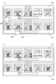
- FIG. 1 is a configuration diagram illustrating a configuration of a medical imaging system according to an embodiment. It is a lineblock diagram showing the composition of the medical image switcher concerning this embodiment. It is a figure showing the 1st operation screen displayed on a touch panel device.
- FIG. 7 is a schematic diagram for explaining an operation method for a first operation screen.
- FIG. 7 is a schematic diagram for explaining an operation method for a first operation screen.
- FIG. 7 is a schematic diagram for explaining an operation method for a first operation screen.
- FIG. 7 is a schematic diagram for explaining an operation method for a first operation screen.
- FIG. 7 is a schematic diagram for explaining an operation method for a first operation screen. It is a figure showing the display mode of the 2nd operation screen displayed on a touch panel device.
- FIG. 1 is a configuration diagram illustrating a configuration of a medical imaging system according to an embodiment. It is a lineblock diagram showing the composition of the medical image switcher concerning this embodiment. It is a figure showing the 1st operation
- FIG. 9 is a schematic diagram for explaining an operation method for a second operation screen.
- FIG. 9 is a schematic diagram for explaining an operation method for a second operation screen.
- FIG. 9 is a schematic diagram for explaining an operation method for a second operation screen. It is a figure showing another display mode of the 2nd operation screen displayed on a touch panel device.
- FIG. 1 is a configuration diagram illustrating a configuration of a medical imaging system 1000 according to the present embodiment. Note that arrows shown in FIG. 1 indicate an output source and an input destination of a video transmitted and received between respective components. Therefore, the exchange of information and data other than video does not necessarily have to match the content indicated by each arrow.
- the medical image system 1000 includes a medical image switcher 100, a medical device group 200 connected to an input channel of the medical image switcher 100, and a monitor group 300 and an encoder 400 connected to an output channel of the medical image switcher 100. ing.
- the medical image system 1000 downloads and stores the image supplied from the encoder 400 via the network 500, requests the server 600 via the network 500 for the image, and transmits the requested image to the server 600.
- a viewer group 700 that acquires and displays (reproduces) the information from the device 600 via the network 500.
- the medical image switcher 100 is a device that inputs medical images from any of a plurality of input channels and outputs the images from an output channel connected to the input channel among the plurality of output channels.
- FIG. 2 is a configuration diagram showing the configuration of the medical image switcher 100.
- the components of the medical image switcher 100 are roughly divided into a switcher main body 110 and a control panel 120.
- the switcher main body 110 has a plurality of input terminals provided for each input channel and a plurality of output terminals provided for each output channel.
- the switcher body 110 has 20 input terminals and 20 output terminals. That is, the switcher main body 110 can input an image from a maximum of 20 input channels, and can output an image from a maximum of 20 output channels.
- the number of input terminals and output terminals of the switcher main body 110 is not limited to the above number (20) and can be changed as appropriate.
- the control panel 120 is a component that receives an operation related to the switcher main body 110, and the operation includes at least an operation of determining an input channel and an output channel to be connected to each other (switching between an input source and an output source).
- the control panel 120 includes a touch panel device 121 and a keyboard 122.
- the touch panel device 121 is a device integrally including a display device capable of displaying an operation screen for operating the switcher main body 110 and a position input device capable of receiving a pointing operation (touch operation) on the operation screen. Since the operation screen includes at least a first operation screen and a second operation screen, which will be described later, the touch panel device 121 can be said to be a configuration that realizes a display unit and an operation input unit according to the present invention.
- the keyboard 122 is a peripheral device connected to the touch panel device 121, and is used for a part of the operation related to the switcher main body 110 (particularly, an operation that requires character input).
- the touch panel device 121 that can realize the display unit and the operation input unit as a single device is exemplified.
- a configuration in which the display unit and the operation input unit are realized as a plurality of devices for example, (A configuration in which a pointing device is separately provided).
- a configuration in which a keyboard 122 is provided as hardware separately from the touch panel device 121 is exemplified.
- a screen keyboard (software keyboard) displayed on the touch panel device 121 instead of or in combination with the keyboard 122 May be adopted.
- an operation field camera 201 is a camera that captures an image of the operative field from a position facing the operative field and outputs the captured image to the medical image switcher 100.
- the head camera 202 is a camera that is set on the head of a practitioner (surgeon) and outputs a captured image to the medical image switcher 100.
- the electronic medical record 203 is a computer device that stores a medical record (medical record) regarding a subject (patient) who undergoes an operation, and outputs the stored medical record to the medical image switcher 100.
- the number of medical records output from the electronic medical record 203 is not limited to one, and may be plural.
- the electronic medical record 203 can output the medical records separately for each input channel of the medical image switcher 100.
- the living body measuring device 204 is a measuring device that measures living body information (blood pressure, pulse rate, electrocardiogram, respiration rate, body temperature, etc.) of the subject and outputs the measured living body information to the medical image switcher 100.
- the endoscope 205 is provided with a lens of a camera, a forceps hole, or the like at a distal end of a tube inserted into the body of the subject, and outputs an image captured by the camera to the medical image switcher 100. It is.
- the microscope 206 is a medical device that enlarges and displays and captures a minute part (such as a nerve or a blood vessel of the subject) to a size that can be seen with the naked eye, and outputs an enlarged and captured image to the medical image switcher 100. It is possible.
- the ultrasonic diagnostic apparatus 207 is a medical device that applies ultrasonic waves to an object (the chest, abdomen, and the like of the subject) to visualize the echo, and is sometimes referred to as an “echo”.
- the ultrasonic diagnostic apparatus 207 can output an image based on the reflected ultrasonic waves to the medical image switcher 100.
- the fluoroscopic imaging device 208 is a medical device that irradiates an object (the subject) with an X-ray and generates an X-ray image based on the transmitted X-ray, and transmits the generated X-ray image to the medical image switcher 100. Output is possible.
- the medical device group 200 described here is a specific example, and some of them may be missing in the implementation of the present invention, or another medical device not listed here may be included.
- video data related to a video or the like (including a medical record or a measurement result of biological information) generated by the medical device group 200, and a device (a monitor group 300 or a viewer group 700 described later) to which the video data is input. ) Will be described below as being equivalent to the “medical image”.
- the monitor group 300 is a display device that inputs video data output from the medical device group 200 via the medical video switcher 100 and displays the input video data.
- the number of display devices corresponding to the monitor group 300 is not particularly limited, and may be a single display device.
- the encoder 400 inputs video data output from the medical device group 200 via the medical video switcher 100, performs encoding processing (encoding) on the input video data, and transfers the video data to the server 600. Convert to a suitable format.
- the encoder 400 in the present embodiment has four input systems, and can input video data from each of the four output channels in the medical video switcher 100, and performs encoding processing on each video data. Can be stored in the server 600.
- the number of input systems of the encoder 400 is not particularly limited, and may be smaller or larger than four.
- the network 500 can be configured by various computer networks such as the Internet and a LAN (Local Area Network) or a combination thereof. Further, the communication connection between the components included in the network may be wired communication, wireless communication, or a combination thereof.
- LAN Local Area Network
- the viewer group 700 is a computer device having an access right to the server 600, and can request display (reproduction) of video data stored in the server 600 according to the access right.
- the server 600 distributes the requested video via the network 500 in response to the display request from the viewer group 700.
- the reproduction of the video by the viewer group 700 may be download reproduction or streaming reproduction.
- the display device corresponding to the monitor group 300 is provided in the operating room, and that the computer device corresponding to the viewer group 700 is provided outside the operating room.
- the display device corresponding to the monitor group 300 may be provided outside the operating room, or at least a part of the computer device corresponding to the viewer group 700 may be provided in the operating room.
- the operation screen displayed on the touch panel device 121 includes at least a first operation screen and a second operation screen.
- the first operation screen is an operation screen for accepting an operation for designating an input channel and an output channel related to a video or the like displayed on the second operation screen.
- the second operation screen is an operation screen for displaying an image related to the input channel and the output channel specified in the first operation screen, and accepting an operation of switching between an input channel and an output channel to be connected.
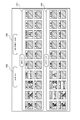
- FIG. 3 is a diagram illustrating a first operation screen displayed on the touch panel device 121.
- 4 to 8 are schematic diagrams for explaining an operation method on the first operation screen.
- the first operation screen includes an input list 1201 displaying 20 display frames (hereinafter, referred to as input frames) corresponding to each of the 20 input channels, and 20 input frames corresponding to each of the 20 output channels.
- An output list 1202 that displays a display frame (hereinafter, referred to as an output frame) is displayed.
- the user can arbitrarily set a name for each of the input frame displayed in the input list 1201 and the output frame displayed in the output list 1202, and the set name is the name of each input frame or each output frame. Displayed at the top.
- each input frame and each output frame conforms to the physical arrangement of the input terminals and output terminals provided on the switcher main body 110.
- the input frames arranged in the upper row of the input list 1201 will be referred to as input frames A1 to A10 in order from the left in order to distinguish and call them.
- the input frames are referred to as input frames A11 to A20 in order from the left.
- the output frames are referred to as output frames B1 to B10 in order from the left.
- output frames are referred to as output frames B11 to B20 in order from the left.
- shaded input frames (specifically, input frames A5 to A7 and input frames A9 to A20) and shaded output frames (specifically, output frames B5 to B10 and output frame B14).
- To B20 are not designated as input frames and output frames to be displayed on the second operation screen (the designations have been canceled), and the other input frames and output frames are displayed on the second operation screen. These are designated as input frames and output frames.
- the name of the "operative field camera” is set, and the video currently being input from the operative field camera 201 (video being captured) Is displayed.
- the name of “head camera” is set, and a thumbnail image of the video (video being captured) currently input from the head camera 202 Is displayed.
- the name of the “electronic medical record” is set, and the image currently input from the electronic medical record 203 (the medical record of the patient). (CT image) is displayed.
- the name of "biological information” is set, and the image (measurement result of the biometric information) currently input from the biometric device 204. Is displayed.
- the input frame A8 corresponding to the input terminal connected to the fluoroscopic imaging device 208 is given the name of “fluoroscopic imaging device”, and the image (X of the subject) currently input from the fluoroscopic imaging device 208 is input. The line image) is displayed.
- the name of “endoscope” is set in the input frame A6 corresponding to the input terminal connected to the endoscope 205, it is not specified as the input frame to be displayed on the second operation screen. Thumbnail images are not displayed.
- the name of “microscope” is set in the input frame A7 corresponding to the input terminal connected to the microscope 206, the thumbnail image is displayed because it is not specified as the input frame to be displayed on the second operation screen. Not done.
- the name of “ultrasonic diagnostic device” is set, but it is not specified as the input frame to be displayed on the second operation screen. Therefore, the thumbnail image is not displayed.
- the input frames A9 to A20 corresponding to the other input terminals have not been set by the user and have not been designated as the input frames to be displayed on the second operation screen (the medical devices corresponding to the input channels). No thumbnail image is displayed because the group 200 does not exist).
- the name “wall monitor” is set in the output frame B1 corresponding to the output terminal connected to the wall monitor (not shown), which is one of the monitor groups 300.
- the input frame A1 is associated with the output frame B1, and the thumbnail image of the video (the video captured by the operation field camera 201) currently input to the input frame A1 is displayed.
- the output frame B2 corresponding to an output terminal connected to a ceiling monitor (not shown), which is one of the monitor groups 300
- the name of “ceiling monitor 1” is set.
- the input frame A4 is associated with the output frame B2, and a thumbnail image of a video (measurement result of biological information) that is currently input is displayed in the input frame A4.
- the output frame B3 which is one of the monitor groups 300 and corresponds to an output terminal connected to a ceiling-mounted monitor (not shown) different from the above-mentioned ceiling-mounted monitor, has a name of “ceiling-mounted monitor 2”. Is set. At the time shown in FIG. 3, the input frame A3 is associated with the output frame B3, and the thumbnail image of the video (CT image, which is a medical record of the patient) currently input to the input frame A3 is displayed. Is done.
- the input frame A8 is associated with the output frame B4, and the thumbnail image of the video (X-ray image of the subject) that is currently being input is displayed in the input frame A8.
- the name of “encoder 1” is set in the output frame B11 corresponding to the output terminal connected to the first input system of the encoder 400.
- the input frame A1 is associated with the output frame B11, and the thumbnail image of the video (the video captured by the operation field camera 201) that is currently input to the input frame A1 is displayed.
- the name of "encoder 2" is set, and the input frame A2 is associated at the time shown in FIG.
- the thumbnail image of the video (video captured by the head camera 202) currently input in the input frame A2 is displayed.
- the name of "encoder 3" is set, and the input frame A4 is associated at the time shown in FIG. Then, a thumbnail image of the video (measurement result of the biological information) currently input in the input frame A4 is displayed.
- the output frame B14 corresponding to the output terminal connected to the fourth input system of the encoder 400 has the name "Encoder 4", but is designated as the output frame to be displayed on the second operation screen. No thumbnail image is displayed.
- the output frames B5 to B10 and B15 to B20 corresponding to the other output terminals have not been set by the user and have not been designated as input frames to be displayed on the second operation screen. Do not show.
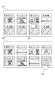
- FIGS. 4 and 5 show a specific example of an operation method for the first operation screen (an operation method for specifying an input channel and an output channel for an image or the like displayed on the second operation screen).
- one or more input frames and one or more output frames are designated based on a pointing operation on the first operation screen from among the input frames and output frames displayed on the first operation screen. By doing so, an input frame or an output frame displayed on the second operation screen can be obtained.
- the “pointing operation on the first operation screen” specifically refers to touching a display area in which an input frame or an output frame to be specified is displayed twice (double touch).
- 5A simulate the movement of the hand of the user who double-touches, and are not actually displayed on the touch panel device 121. Absent. Note that the double touch described here is a specific example of an operation of specifying an input frame or an output frame to be displayed on the second operation screen. Instead of this operation or in combination with this operation, another pointing operation is performed. A similar process may be realized.
- the thumbnail image of the video (the video captured by the head camera 202) displayed in the input frame A2 is displayed as a double image.
- Recognition becomes more difficult than before the touch (for example, the brightness of the thumbnail image is reduced).
- the user can recognize that the designation has been canceled (not designated) (see FIG. 4B).
- the display mode of the output frame B14 changes (for example, the brightness of the output frame B14 is improved). This allows the user to recognize the designation (see FIG. 5B).
- a display mode in which a designated input frame (or output frame) and a deselected input frame (or output frame) can be distinguished.
- the present invention is not limited to this.
- the presence / absence of the designation may be displayed separately from the input frame or the output frame, or the presence / absence of the designation may be represented by a part of the input frame or the output frame (the color of the frame portion or the like).
- an input frame in which no image is input from the medical device group 200 and an output frame associated with the input frame during the period in which the first operation screen is displayed can be displayed on the second operation screen.
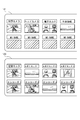
- FIGS. One specific example of an operation method for the first operation screen (an operation method for associating the input frame displayed on the first operation screen with the output frame displayed on the first operation screen) is shown in FIGS. .
- the pointing symbols OP3 and OP4 shown in FIG. 6 simulate the movement of the user's hand performing drag and release, and are not actually displayed on the touch panel device 121.
- drag and release specifically means that after the pointing operation on one input frame A3 is received on the first operation screen, the position of the pointing operation is changed while the pointing operation is continued. This is an operation method of moving from the input frame A3 to one output frame B14, and canceling the pointing operation in the output frame B14.
- the medical image switcher 100 associates the input frame A3 with the output frame B14.
- the copy image CP1 of the thumbnail image displayed in the input frame moves in accordance with the movement of the pointing operation, and
- the copy image CP1 of the thumbnail image disappears.
- the pointing symbols OP5 and OP6 shown in FIG. 7 simulate the movement of the user's hand touching the input frame A3 and the output frame B14 one time each (one touch at a time). It is not displayed on the device 121.
- the “one touch at a time” is, specifically, an operation method in which, on the first operation screen, after receiving a pointing operation for one input frame A3, a new pointing operation for one output frame B14 is received. . Even when the operation method is received, the medical image switcher 100 associates the input frame A3 with the output frame B14. In this case, in contrast to the case shown in FIG. 6 (when drag and release is received), a pointing operation for one input box A3 is received, and then a new pointing operation for one output box B14 is received. Until the above, there is a difference that a copy image (corresponding to the copy image CP1) of the thumbnail image displayed in the input frame A3 is not displayed.
- the input frame A3 and the output frame B14 are associated with each other, and as a result, the thumbnail of the video (CT image of the subject) currently input to the input frame A3 is output to the output frame B14. An image is displayed (see FIG. 8).
- “Drag and release” and “one touch” for the first operation screen display the first operation screen at the preparation stage of the operation (before displaying the second operation screen) and at the beginning of the operation (display the second operation screen) ),
- the output frame and the input frame are associated with each other.
- drag and release” and “one touch” are specific examples of the operation of associating the input frame displayed on the first operation screen with the output frame displayed on the first operation screen.
- the same processing may be realized by another pointing operation instead of or in combination with this operation.
- a layout list display button 1203 and a layout save button 1204 are provided in addition to the input list 1201 and the output list 1202.
- the layout save button 1204 is used for the current layout of the first operation screen (specifically, the correspondence between the input frame and the output frame in the first operation screen, the names set for the input and output frames in the first operation screen). , And whether or not these input frames and output frames are specified) are pointed.
- a name can be set for the layout to be stored, and different layouts can be stored depending on the surgical procedure, the operator, and the like.
- a layout list display button 1203 is used to perform a pointing operation when displaying a layout list (not shown) of the first operation screen saved so far. When the layout displayed in the list is specified, the first operation screen is changed to the specified new layout.
- the first operation screen is a pointing operation (shown in FIGS. 6 and 7) for associating the input frame displayed on the first operation screen with the output frame displayed on the first operation screen.
- Pointing operation is a pointing operation (FIGS. 4 and 5) for designating an input frame and an output frame to be displayed on the second operation screen from the input frame and the output frame displayed on the first operation screen. (Pointing operation shown in FIG. 3) can be accepted.
- the first operation screen includes a pointing operation (at least a correspondence between the input frame and the output frame based on the first pointing operation and the designation of the input frame and the output frame based on the second pointing operation).
- a pointing operation on the layout save button 1204 can be accepted.
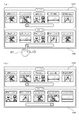
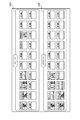
- FIG. 9 is a diagram illustrating a second operation screen displayed on the touch panel device 121.
- 10 to 12 are schematic diagrams for explaining an operation method for the second operation screen.
- the second operation screen displays an input frame and an output frame designated based on a pointing operation on the first operation screen.
- Each input frame is displayed in an input list 1205, and each output frame is an output frame. It is displayed in the list 1206.
- the input frames arranged in the input list 1205 are referred to as input frames C1 to C5 in order from the left to distinguish and call them.
- the output frames are referred to as output frames D1 to D5 in order from the left.
- the second operation screen illustrated in FIG. 9 is based on the settings described with reference to FIG. More specifically, in the input list 1205, an input frame C1 displayed by specifying the input frame A1, an input frame C2 displayed by specifying the input frame A2, and an input displayed by specifying the input frame A5 are displayed. A frame C3, an input frame C4 displayed by specifying the input frame A11, and an input frame C5 displayed by specifying the input frame A12 are included.
- the output list 1206 includes an output frame D1 displayed by specifying the output frame B1, an output frame D2 displayed by specifying the output frame B2, an output frame D4 displayed by specifying the output frame B3, An output frame D4 displayed by specifying the output frame B4 and an output frame D5 displayed by specifying the output frame B11 are included.
- the input frame displayed in the input list 1205 and the output frame displayed in the output list 1206 include the name and the output list set in the input frame displayed in the corresponding input list 1201. The name set for the output frame displayed in 1202 is given.
- the second operation screen displays the input frame and the output frame specified in the first operation screen with the input frame and the output frame left-justified. That is, the arrangement of the input frame and the output frame displayed on the second operation screen can be expressed as being aggregated as compared with the arrangement of the input frame and the output frame specified on the first operation screen.
- the change of the arrangement of the input frame and the output frame displayed on the second operation screen is not limited to the left justification as in the present embodiment, and may be compared with the arrangement of the input frame and the output frame displayed on the first operation screen. Anything that can be easily viewed by the user is sufficient.
- the number of input frames and output frames displayed on the second operation screen is five each, which is smaller than the number of input frames and output frames (20 each) on the first operation screen.
- the input frame and the output frame displayed on the second operation screen can be enlarged as compared with the input frame and the output frame displayed on the first operation screen. For this reason, the input frame and the output frame displayed on the second operation screen can be more easily recognized by the user than the input frame and the output frame displayed on the first operation screen.
- FIG. 10 illustrates a specific example of the operation related to the slide bar.
- the pointing symbol OP7 illustrated in FIG. 10A simulates the movement of the user's hand that slides the buttons of the slide bar to the right, and is not actually displayed on the touch panel device 121.
- the output frame displayed outside the display area specifically, the output frame An output frame D6 displayed by specifying the output frame B12 and an output frame D7 displayed by specifying the output frame B13 are displayed in the display area (see FIG. 10B).
- the operation related to the slide bar described in the present embodiment is a specific example of an operation of displaying an input frame or an output frame outside the display area in the display area on the second operation screen, instead of this operation or this operation.
- a similar process may be implemented by a swipe operation on the input list 1205 or the output list 1206 (operation of rubbing the screen of the touch panel device 121 in the left-right direction) in combination.
- the medical image switcher 100 performs a pointing operation on the second operation screen with respect to one of the input frames displayed on the second operation screen with respect to any one of the output frames displayed on the second operation screen.
- the input channel corresponding to the input frame and the output channel corresponding to the output frame associated based on the pointing operation on the second operation screen can be connected.
- the “pointing operation on the second operation screen” specifically has two patterns shown in FIGS. 11 and 12.
- FIG. 11 illustrates a specific example of the above-described “pointing operation on the second operation screen”.
- the pointing symbols OP8 and OP9 shown in FIG. 11A simulate the movement of the user's hand performing drag and release, and are not actually displayed on the touch panel device 121.
- “drag and release” means that, after a pointing operation on one input frame C1 is received on the second operation screen, the position of the pointing operation is changed to an input frame while the pointing operation is continued.
- the medical image switcher 100 moves from C1 to one output frame D2 and releases the pointing operation in the output frame D2.
- the operation method hereinafter, referred to as a first case
- the medical image switcher 100 When the operation method is received (hereinafter, referred to as a first case), the medical image switcher 100 ,
- the input frame C1 is associated with the output frame D2.
- the copy image CP2 of the thumbnail image displayed in the input frame is displayed on the second operation screen. It moves in accordance with the movement, and when the pointing operation is released, the copy image CP2 of the thumbnail image disappears.
- FIG. 12 illustrates another specific example of the “pointing operation on the second operation screen”.
- the pointing symbols OP10 and OP11 shown in FIG. 12A simulate the movement of the user's hand touching the input frame C1 and the output frame D2 once (one touch each). It is not actually displayed on the touch panel device 121.
- the term “per touch” is specifically an operation method in which, on the second operation screen, after receiving a pointing operation for one input frame C1, a pointing operation for one output frame D2 is newly received. Even when the operation method is received (hereinafter, referred to as a second case), the medical image switcher 100 associates the input frame C1 with the output frame D2.
- “Drag and release” and “one touch” for the second operation screen assume that the output frame and the input frame during the operation (when the second operation screen is displayed) are associated with each other. In other words, it is assumed that a situation where hands are taken in other work and a situation where image switching operation frequently occurs rather than a preparation stage for surgery (a stage where the first operation screen is displayed). Operation is facilitated by thinning out the displayed input and output frames in the preparation stage. Note that the above “drag and release” and “one touch” are specific examples of the operation of associating the input frame displayed on the second operation screen with the output frame displayed on the second operation screen. The same processing may be realized by another pointing operation instead of or in combination with this operation.
- FIGS. 11 (b) and 12 (b) As shown, in each case, the thumbnail image displayed in the output frame D2 is switched from the measurement result of the biometric device 204 to the video image of the operation field camera 201. As described above, the same process for switching the video (the process of associating the input frame C1 and the output frame D2) is realized by a plurality of operation methods. Can be switched. In addition, since the display mode changes when each operation is received (the presence / absence of the copy image CP2 is different), the user can visually identify which operation is being performed. It is possible to suppress human errors such as erroneous operations and viewing mistakes.
- the thumbnail images displayed in the output frame D1 and the output frame D2 are based on the video of the same content (both are the video captured by the surgical field camera 201). That is, the same video can be output from the output channels corresponding to the output frames D1 and D2. That is, the medical image switcher 100 corresponds to the input frame when a plurality of output frames displayed on the second operation screen are associated with one input frame displayed on the second operation screen. In other words, the video input from the input channel is output from each of the output channels corresponding to the plurality of output frames.
- the touch panel device 121 can separately display the first operation screen and the second operation screen having the above-described features, and the user can input from the medical device group 200 according to the display. Switching can be performed with respect to the video and the like. Therefore, the operation related to switching is further simplified, and as a result, erroneous operation by the user is suppressed.
- the medical image switcher according to the present invention is not limited to the case where it is used as a component of the medical image system 1000 shown in FIG. 1, but may be used as a component of another system.
- the medical image switcher according to the present invention is an invention that is established as a single unit regardless of the configuration of peripheral devices.
- the medical image switcher according to the present invention is not limited to the configuration illustrated in FIG. 2, and the configuration can be appropriately changed without impairing the spirit of the present invention.
- the switcher main body 110 and the control panel 120 are integrated. (Single device).
- the second operation screen of the medical image switcher according to the present invention is not limited to a mode in which the input frame and the output frame are fixed to five as shown in FIG. You may.
- the number of input frames and output frames displayed on the second operation screen does not necessarily have to be the same, and one may be larger than the other.
- the number of input frames and output frames displayed on the first operation screen shown in FIG. 3 are designated to be displayed on the second operation screen, as shown in FIG. It may be possible to adjust the number of input frames and output frames displayed at one time to 20 each. At this time, even if the display size of the input and output frames displayed on the second operation screen is equal to the display size of the number of input and output frames displayed on the first operation screen. Good.
- the input frame and the output frame are displayed in an enlarged manner.
- the number of input frames and output frames displayed on the second operation screen is equal to the number of input frames and output frames displayed on the first operation screen (for example, as shown in FIG. 13)
- the image is displayed in a size substantially equal to the size of the frame and the output frame.
- a medical image switcher for inputting a medical image from any of a plurality of input channels and outputting the image from an output channel connected to the input channel among the plurality of output channels, wherein at least a first operation screen and a second Display means capable of displaying an operation screen, and operation input means capable of accepting a pointing operation on the first operation screen and the second operation screen, wherein the first operation screen includes a plurality of input channels.
- the first operation screen includes a plurality of input channels.
- the second operation screen displays the input frame and the output frame specified based on a pointing operation on the first operation screen, and the input frame displayed on the second operation screen
- One of the input frames is associated with one of the output frames displayed on the second operation screen based on a pointing operation on the second operation screen, and a pointing operation on the second operation screen is performed.
- the arrangement of the input frame and the output frame displayed on the second operation screen is aggregated as compared with the arrangement of the input frame and the output frame specified on the first operation screen (1).
- the medical image switcher according to 1.
- the input frame and the output frame displayed on the second operation screen can be enlarged as compared with the input frame and the output frame displayed on the first operation screen (1) or (2).
- the medical image switcher according to 1. (4) When the input frame and the output frame displayed on the second operation screen are smaller than the number of the input frame and the output frame displayed on the first operation screen, the input frame and the output frame When the input frame and the output frame displayed on the second operation screen are displayed larger than the output frame and are equal to the number of the input frames and the output frames displayed on the first operation screen.
- the medical image switcher according to (3) which is displayed in a size substantially equal to the input frame and the output frame.
- the position of the pointing operation moves from the input frame to the one output frame while the pointing operation is continued. Then, in the first case in which the pointing operation is released in the output frame, the input frame is associated with the output frame, and in the second operation screen, after the pointing operation for one of the input frames is received,
- the medical image switcher according to any one of (1) to (4), wherein the input frame is associated with the output frame also in a second case in which a pointing operation is newly performed on one of the output frames.
- a thumbnail image of the video currently being input is displayed.
- the thumbnail image is displayed in the input frame.
- the copy image of the thumbnail image moves in accordance with the movement of the pointing operation, and when the pointing operation is released, the copy image of the thumbnail image disappears.
- one of the input frames (5)
- the medical image switcher according to (5) wherein a copy image of the thumbnail image displayed in the input frame is not displayed until a pointing operation for a new one of the output frames is received after a pointing operation for the input frame is received.
- the first operation screen includes: a first pointing operation for associating the input frame displayed on the first operation screen with the output frame displayed on the first operation screen; From the input frame and the output frame displayed on the operation screen, a second pointing operation for designating the input frame and the output frame to be displayed on the second operation screen, and at least the first pointing A third pointing operation for saving the correspondence between the input frame and the output frame based on the operation and the designation of the input frame and the output frame based on the second pointing operation can be accepted.
- the medical image switcher according to any one of (1) to (8).
Landscapes
- Engineering & Computer Science (AREA)
- Health & Medical Sciences (AREA)
- Life Sciences & Earth Sciences (AREA)
- Physics & Mathematics (AREA)
- General Engineering & Computer Science (AREA)
- Theoretical Computer Science (AREA)
- Surgery (AREA)
- Multimedia (AREA)
- Signal Processing (AREA)
- Human Computer Interaction (AREA)
- General Physics & Mathematics (AREA)
- Nuclear Medicine, Radiotherapy & Molecular Imaging (AREA)
- Biomedical Technology (AREA)
- Veterinary Medicine (AREA)
- Pathology (AREA)
- Public Health (AREA)
- General Health & Medical Sciences (AREA)
- Heart & Thoracic Surgery (AREA)
- Medical Informatics (AREA)
- Molecular Biology (AREA)
- Animal Behavior & Ethology (AREA)
- Radiology & Medical Imaging (AREA)
- Optics & Photonics (AREA)
- Oral & Maxillofacial Surgery (AREA)
- Biophysics (AREA)
- Gynecology & Obstetrics (AREA)
- Databases & Information Systems (AREA)
- Astronomy & Astrophysics (AREA)
- User Interface Of Digital Computer (AREA)
- Two-Way Televisions, Distribution Of Moving Picture Or The Like (AREA)
- Instruments For Viewing The Inside Of Hollow Bodies (AREA)
- Endoscopes (AREA)
- Closed-Circuit Television Systems (AREA)
- Measuring And Recording Apparatus For Diagnosis (AREA)
Abstract
L'invention concerne un commutateur d'image médicale qui peut être actionné plus facilement par un utilisateur. Sur la base d'une opération de pointage sur un premier écran de commande sur lequel sont affichées une pluralité de trames d'entrée, correspondant respectivement à une pluralité de canaux d'entrée, et une pluralité de trames de sortie, correspondant respectivement à une pluralité de canaux de sortie, le commutateur d'image médicale (100) spécifie une ou plusieurs trames d'entrée et une ou plusieurs trames de sortie. Sur la base d'une opération de pointage sur un second écran de commande sur lequel les trames d'entrée et les trames de sortie spécifiées sur la base de l'opération de pointage sur le premier écran de commande sont affichées, le commutateur d'image médicale (100) associe une trame d'entrée à l'une des trames de sortie et connecte le canal d'entrée correspondant à la trame d'entrée associée au canal de sortie correspondant à la trame de sortie.
Priority Applications (2)
| Application Number | Priority Date | Filing Date | Title |
|---|---|---|---|
| CN201980058005.0A CN112654281B (zh) | 2018-09-06 | 2019-08-02 | 医疗影像切换器 |
| US17/266,022 US20210385391A1 (en) | 2018-09-06 | 2019-08-02 | Medical video switcher |
Applications Claiming Priority (2)
| Application Number | Priority Date | Filing Date | Title |
|---|---|---|---|
| JP2018-167233 | 2018-09-06 | ||
| JP2018167233A JP6440136B1 (ja) | 2018-09-06 | 2018-09-06 | 医療映像スイッチャー |
Publications (1)
| Publication Number | Publication Date |
|---|---|
| WO2020049920A1 true WO2020049920A1 (fr) | 2020-03-12 |
Family
ID=64668566
Family Applications (1)
| Application Number | Title | Priority Date | Filing Date |
|---|---|---|---|
| PCT/JP2019/030481 Ceased WO2020049920A1 (fr) | 2018-09-06 | 2019-08-02 | Commutateur d'image médicale |
Country Status (4)
| Country | Link |
|---|---|
| US (1) | US20210385391A1 (fr) |
| JP (1) | JP6440136B1 (fr) |
| CN (1) | CN112654281B (fr) |
| WO (1) | WO2020049920A1 (fr) |
Families Citing this family (2)
| Publication number | Priority date | Publication date | Assignee | Title |
|---|---|---|---|---|
| JP6857372B1 (ja) | 2020-02-06 | 2021-04-14 | 株式会社Medi Plus | 医療映像処理システム及びエンコード装置 |
| JP6948043B1 (ja) * | 2020-08-05 | 2021-10-13 | 株式会社Medi Plus | 医療映像システム及び医療映像処理装置 |
Citations (3)
| Publication number | Priority date | Publication date | Assignee | Title |
|---|---|---|---|---|
| JP2016036592A (ja) * | 2014-08-08 | 2016-03-22 | オリンパス株式会社 | 医療システム |
| WO2016189949A1 (fr) * | 2015-05-22 | 2016-12-01 | オリンパス株式会社 | Système de traitement médical |
| WO2017056762A1 (fr) * | 2015-10-02 | 2017-04-06 | ソニー株式会社 | Dispositif de commande médical, procédé de commande, programme et système de commande médical |
Family Cites Families (14)
| Publication number | Priority date | Publication date | Assignee | Title |
|---|---|---|---|---|
| JP2002233536A (ja) * | 2001-02-08 | 2002-08-20 | Olympus Optical Co Ltd | 内視鏡手術システム |
| JP4508981B2 (ja) * | 2005-08-18 | 2010-07-21 | ティーオーエー株式会社 | モニタディスプレイ装置及びそれを用いた監視システム |
| EP2612592A4 (fr) * | 2010-08-31 | 2014-06-25 | Fujifilm Corp | Dispositif ainsi que procédé d'affichage d'informations médicales, et programme |
| CN103188987B (zh) * | 2010-11-02 | 2015-08-05 | 伊顿株式会社 | 手术机器人系统及其腹腔镜操作方法以及体感式手术用图像处理装置及其方法 |
| CN105120734B (zh) * | 2013-04-03 | 2017-03-08 | 奥林巴斯株式会社 | 显示三维影像的内窥镜系统 |
| EP3037939A4 (fr) * | 2013-11-21 | 2017-05-31 | Olympus Corporation | Dispositif d'affichage d'image |
| WO2015151780A1 (fr) * | 2014-04-02 | 2015-10-08 | ソニー株式会社 | Dispositif de commande de connexion et procédé de commande de connexion |
| JP6501525B2 (ja) * | 2015-01-08 | 2019-04-17 | キヤノン株式会社 | 情報処理装置、情報処理方法およびプログラム |
| WO2016158593A1 (fr) * | 2015-03-30 | 2016-10-06 | テルモ株式会社 | Dispositif et procédé de traitement d'image, et programme |
| TW201635970A (zh) * | 2015-04-10 | 2016-10-16 | Huede Healthtech Co Ltd | 醫療影像的多螢幕播送裝置及其程序執行方式 |
| JP6490001B2 (ja) * | 2015-12-25 | 2019-03-27 | ウエストユニティス株式会社 | メディカルシステム |
| JP6352503B2 (ja) * | 2016-09-30 | 2018-07-04 | 株式会社Medi Plus | 医療動画像表示システム |
| JP6369706B1 (ja) * | 2017-12-27 | 2018-08-08 | 株式会社Medi Plus | 医療動画処理システム |
| JP6360271B1 (ja) * | 2018-04-06 | 2018-07-18 | 株式会社Medi Plus | 医療動画処理システム |
-
2018
- 2018-09-06 JP JP2018167233A patent/JP6440136B1/ja active Active
-
2019
- 2019-08-02 WO PCT/JP2019/030481 patent/WO2020049920A1/fr not_active Ceased
- 2019-08-02 US US17/266,022 patent/US20210385391A1/en not_active Abandoned
- 2019-08-02 CN CN201980058005.0A patent/CN112654281B/zh active Active
Patent Citations (3)
| Publication number | Priority date | Publication date | Assignee | Title |
|---|---|---|---|---|
| JP2016036592A (ja) * | 2014-08-08 | 2016-03-22 | オリンパス株式会社 | 医療システム |
| WO2016189949A1 (fr) * | 2015-05-22 | 2016-12-01 | オリンパス株式会社 | Système de traitement médical |
| WO2017056762A1 (fr) * | 2015-10-02 | 2017-04-06 | ソニー株式会社 | Dispositif de commande médical, procédé de commande, programme et système de commande médical |
Also Published As
| Publication number | Publication date |
|---|---|
| JP6440136B1 (ja) | 2018-12-19 |
| US20210385391A1 (en) | 2021-12-09 |
| JP2020039432A (ja) | 2020-03-19 |
| CN112654281B (zh) | 2024-10-29 |
| CN112654281A (zh) | 2021-04-13 |
Similar Documents
| Publication | Publication Date | Title |
|---|---|---|
| US10631712B2 (en) | Surgeon's aid for medical display | |
| US8328793B2 (en) | Device, system and method for integrating different medically applicable apparatuses | |
| US9526586B2 (en) | Software tools platform for medical environments | |
| US11412998B2 (en) | Multi-source medical display | |
| US20090268986A1 (en) | System for the playback of medical images | |
| JP2000107136A (ja) | 画像表示型の医療診断装置を用いて得られた画像情報を表示するための画像システム | |
| WO2004104921A2 (fr) | Systeme et procede de traitement automatique d'images endoscopiques | |
| US10674968B2 (en) | Adjustable overlay patterns for medical display | |
| US11694725B2 (en) | Information processing apparatus and information processing method | |
| JP2005110878A (ja) | 手術支援システム | |
| EP4376402A1 (fr) | Système de traitement d'informations, procédé de traitement d'informations, et programme | |
| JP2020081280A (ja) | 画像表示制御システム、画像表示システム及び画像解析装置 | |
| KR20130053587A (ko) | 의료기기 및 이를 이용한 의료영상 디스플레이 방법 | |
| CN101441863A (zh) | 用于在大显示器上显示医学图像的输入装置 | |
| JP6440136B1 (ja) | 医療映像スイッチャー | |
| JP6948043B1 (ja) | 医療映像システム及び医療映像処理装置 | |
| US11806181B2 (en) | Display system, display control device, and display control method | |
| JP2005111081A (ja) | 内視鏡画像表示処理装置 | |
| JP2004194704A (ja) | 医用画像診断装置 | |
| US12619780B2 (en) | Information processing system and information processing method | |
| EP2866162A1 (fr) | Affichage médical multisources | |
| US12027257B2 (en) | Beacon-based systems and methods for generating medical facility metrics | |
| JP5322570B2 (ja) | 医用画像処理装置 | |
| WO2024202956A1 (fr) | Dispositif de traitement de données médicales et système médical | |
| CN119817092A (zh) | 信息处理装置、信息处理系统以及信息处理程序 |
Legal Events
| Date | Code | Title | Description |
|---|---|---|---|
| 121 | Ep: the epo has been informed by wipo that ep was designated in this application |
Ref document number: 19856898 Country of ref document: EP Kind code of ref document: A1 |
|
| NENP | Non-entry into the national phase |
Ref country code: DE |
|
| 122 | Ep: pct application non-entry in european phase |
Ref document number: 19856898 Country of ref document: EP Kind code of ref document: A1 |