WO2020054488A1 - Appareil de distribution de boisson - Google Patents
Appareil de distribution de boisson Download PDFInfo
- Publication number
- WO2020054488A1 WO2020054488A1 PCT/JP2019/034484 JP2019034484W WO2020054488A1 WO 2020054488 A1 WO2020054488 A1 WO 2020054488A1 JP 2019034484 W JP2019034484 W JP 2019034484W WO 2020054488 A1 WO2020054488 A1 WO 2020054488A1
- Authority
- WO
- WIPO (PCT)
- Prior art keywords
- hot water
- beverage
- extractor
- supplied
- unit
- Prior art date
- Legal status (The legal status is an assumption and is not a legal conclusion. Google has not performed a legal analysis and makes no representation as to the accuracy of the status listed.)
- Ceased
Links
Images













Classifications
-
- A—HUMAN NECESSITIES
- A47—FURNITURE; DOMESTIC ARTICLES OR APPLIANCES; COFFEE MILLS; SPICE MILLS; SUCTION CLEANERS IN GENERAL
- A47J—KITCHEN EQUIPMENT; COFFEE MILLS; SPICE MILLS; APPARATUS FOR MAKING BEVERAGES
- A47J31/00—Apparatus for making beverages
- A47J31/42—Beverage-making apparatus with incorporated grinding or roasting means for coffee
-
- A—HUMAN NECESSITIES
- A47—FURNITURE; DOMESTIC ARTICLES OR APPLIANCES; COFFEE MILLS; SPICE MILLS; SUCTION CLEANERS IN GENERAL
- A47J—KITCHEN EQUIPMENT; COFFEE MILLS; SPICE MILLS; APPARATUS FOR MAKING BEVERAGES
- A47J31/00—Apparatus for making beverages
- A47J31/24—Coffee-making apparatus in which hot water is passed through the filter under pressure, i.e. in which the coffee grounds are extracted under pressure
- A47J31/32—Coffee-making apparatus in which hot water is passed through the filter under pressure, i.e. in which the coffee grounds are extracted under pressure with hot water under air pressure
-
- A—HUMAN NECESSITIES
- A47—FURNITURE; DOMESTIC ARTICLES OR APPLIANCES; COFFEE MILLS; SPICE MILLS; SUCTION CLEANERS IN GENERAL
- A47J—KITCHEN EQUIPMENT; COFFEE MILLS; SPICE MILLS; APPARATUS FOR MAKING BEVERAGES
- A47J31/00—Apparatus for making beverages
- A47J31/06—Filters or strainers for coffee or tea makers ; Holders therefor
-
- A—HUMAN NECESSITIES
- A47—FURNITURE; DOMESTIC ARTICLES OR APPLIANCES; COFFEE MILLS; SPICE MILLS; SUCTION CLEANERS IN GENERAL
- A47J—KITCHEN EQUIPMENT; COFFEE MILLS; SPICE MILLS; APPARATUS FOR MAKING BEVERAGES
- A47J31/00—Apparatus for making beverages
- A47J31/40—Beverage-making apparatus with dispensing means for adding a measured quantity of ingredients, e.g. coffee, water, sugar, cocoa, milk, tea
- A47J31/401—Beverage-making apparatus with dispensing means for adding a measured quantity of ingredients, e.g. coffee, water, sugar, cocoa, milk, tea whereby the powder ingredients and the water are delivered to a mixing bowl
-
- A—HUMAN NECESSITIES
- A47—FURNITURE; DOMESTIC ARTICLES OR APPLIANCES; COFFEE MILLS; SPICE MILLS; SUCTION CLEANERS IN GENERAL
- A47J—KITCHEN EQUIPMENT; COFFEE MILLS; SPICE MILLS; APPARATUS FOR MAKING BEVERAGES
- A47J31/00—Apparatus for making beverages
- A47J31/44—Parts or details or accessories of beverage-making apparatus
- A47J31/4403—Constructional details
- A47J31/4407—Lids, covers or knobs
-
- G—PHYSICS
- G07—CHECKING-DEVICES
- G07F—COIN-FREED OR LIKE APPARATUS
- G07F13/00—Coin-freed apparatus for controlling dispensing or fluids, semiliquids or granular material from reservoirs
-
- G—PHYSICS
- G07—CHECKING-DEVICES
- G07F—COIN-FREED OR LIKE APPARATUS
- G07F13/00—Coin-freed apparatus for controlling dispensing or fluids, semiliquids or granular material from reservoirs
- G07F13/06—Coin-freed apparatus for controlling dispensing or fluids, semiliquids or granular material from reservoirs with selective dispensing of different fluids or materials or mixtures thereof
Definitions
- the present invention relates to a beverage supply device.
- Patent Document 1 Conventionally, a beverage supply device for supplying a beverage to a container has been proposed in Patent Document 1.
- the beverage supply device proposed in Patent Literature 1 supplies pressurized air for stirring to an extractor to which raw materials pulverized by a pulverizer are supplied and hot water is supplied by hot water supply means, and the raw materials are mixed. After stirring with hot water, pressurized air for extraction is supplied to extract the beverage, which is then supplied to a container such as a cup.
- the extractor when the supply amount of the beverage to the container is equal to or larger than the capacity of the extractor, the extractor after supplying the pressurized air for extraction to extract the beverage is used. After the hot water is supplied again through the hot water supply means, pressurized air for stirring is supplied and stirred, and then the beverage is extracted by supplying the pressurized air for extraction again, and the beverage is supplied to the container. Is common. Since the stirring is performed after the hot water is supplied again, the time required for supplying the beverage to the container is prolonged.
- the present invention has been made in view of the above circumstances, and has as its object to provide a beverage supply device capable of shortening the beverage supply time even when the supply amount of the beverage to the container is equal to or larger than the capacity of the extractor. .
- the beverage supply device is configured such that, while the raw material crushed by the crusher is supplied, the pressurized air for stirring is supplied to the extractor to which the hot water is supplied by the hot water supply means.
- the control unit causes the hot water supply unit to add hot water to the extractor during extraction of the beverage when a supply amount of the beverage to the container is equal to or larger than a volume of the extractor. It is characterized by the following.
- control means causes the hot water supply means to add hot water to the brewing machine which is extracting the beverage by being pressurized while the inside is closed. It is characterized by the following.
- the present invention is also characterized in that, in the beverage supply device, the control means changes a supply speed of the hot water by the hot water supply means according to a kind of the beverage to be supplied.
- the present invention is also characterized in that, in the beverage supply device, the control means changes the pressure of the pressurized air for stirring supplied to the extractor according to the type of beverage to be supplied.
- the present invention is also characterized in that, in the beverage supply device, the hot water supply means swirls and supplies the hot water in such a manner as to abut on an inner wall surface of a cylinder constituting the extractor.
- the present invention also provides the beverage supply device, wherein the hot water supply means includes: a first sending unit that sends a fixed amount of hot water from a hot water tank that stores hot water to an auxiliary tank; And a second transmission unit for transmitting the data to the second transmission unit.
- the hot water supply means includes: a first sending unit that sends a fixed amount of hot water from a hot water tank that stores hot water to an auxiliary tank; And a second transmission unit for transmitting the data to the second transmission unit.
- the present invention is also characterized in that, in the beverage supply device, the second delivery unit has a delivery amount larger than the delivery amount of the first delivery unit.
- the present invention is also characterized in that in the beverage supply device, the substantially cylindrical cylinder constituting the extractor is configured such that an opening edge of an upper surface opening and a lower surface opening is sealed with a sealing material.
- the sealing material includes a plurality of endless protrusions formed on an inner peripheral surface of the beverage supply device, and is formed on an inner surface of a mounting recess formed on the opening edge.
- the projection is abutted while being elastically deformed, so that the projection is attached to the mounting recess and the edge of the opening is sealed.
- the sealing material is formed with a locking projection protruding radially outward on a part of an outer peripheral surface, and a locking hole formed in the mounting recess is formed.
- the locking projection is inserted from the inside to be mounted in the mounting recess to seal the opening edge.
- the control means when the supply amount of the beverage to the container is equal to or larger than the capacity of the extractor, the control means causes the hot water supply means to add the hot water to the extractor during the extraction of the beverage. Is supplied again and agitated, whereas the effect of shortening the supply time of the beverage can be achieved.
- the first sending unit sends a fixed amount of hot water from the hot water tank to the auxiliary tank
- the second sending unit pressurizes the hot water in the auxiliary tank and sends it to the extractor. Since a fixed amount of hot water temporarily stored in the tank is supplied, it is possible to satisfactorily supply a predetermined amount even when the hot water is pressurized to the extractor.
- the second sending section since the second sending section has a larger sending amount than the first sending section, the second sending section has an effect that the hot water can be prevented from overflowing from the auxiliary tank.
- the substantially cylindrical cylinder constituting the extractor is configured such that the opening edges of the upper surface opening and the lower surface opening are sealed with a sealing material. This eliminates the need to remove the extractor, and can simplify the cleaning operation of the extractor.
- FIG. 1 is a perspective view illustrating an external configuration of a beverage supply device according to an embodiment of the present invention.
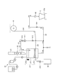
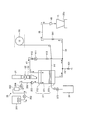
- Drawing 2 is a mimetic diagram showing typically each component of a drink supply device which is an embodiment of the invention.
- FIG. 3 is a front view showing the internal structure of the main body cabinet shown in FIG.
- FIG. 4 is a perspective view showing the structure of the front door shown in FIG.
- FIG. 5 is a perspective view showing the raw material box shown in FIG.
- FIG. 6 is a perspective view showing the raw material box shown in FIG. 2 and its peripheral structure.
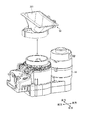
- FIG. 7 is an exploded perspective view showing the pulverizer shown in FIG. 2 and its peripheral structure.
- FIG. 8 is a perspective view showing the raw material chute shown in FIGS. 6 and 7.
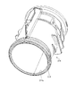
- FIG. 9 is a perspective view showing the cylinder shown in FIG.
- FIG. 10 is a perspective view showing the cylinder shown in FIG.
- FIG. 11 is an exploded perspective view of a main part of the cylinder shown in FIG.
- FIG. 12 is an exploded perspective view of a main part of the cylinder shown in FIG.
- FIG. 13 is a longitudinal sectional view of the sealing material shown in FIGS.
- FIG. 14 is a longitudinal sectional view of the cylinder shown in FIG.
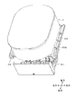
- FIG. 15 is a perspective view showing a mounting structure of the filter block shown in FIG.
- FIG. 16 is an exploded perspective view showing the filter block shown in FIG. 15 and its peripheral structure.
- FIG. 17 is a perspective view showing a mounting structure of the filter block shown in FIG. FIG.
- FIG. 18 is a sectional view showing the operation of the filter block shown in FIG.
- FIG. 19 is a plan view of the storage box shown in FIG.
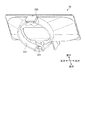
- FIG. 20 is an exploded perspective view showing an attached state of the nozzle shown in FIG.
- FIG. 21 is a perspective view showing a mounting state of the nozzle shown in FIG. 2 in a cross section.
- FIG. 22 is an exploded perspective view showing the configuration of the nozzle shown in FIGS. 20 and 21.
- FIG. 23 is a perspective view showing the nozzle body shown in FIG.
- FIG. 24 is a perspective view showing the configuration of the fan box shown in FIG.
- FIG. 25 is an exploded perspective view showing the configuration of the fan box shown in FIG.
- FIG. 26 is a plan view showing a rail portion of the fan box shown in FIGS. 24 and 25.
- FIG. 27 is a schematic diagram illustrating a procedure of supplying a beverage by the sales control unit of the control unit illustrated in FIG. 2.
- FIG. 28 is a schematic diagram illustrating a procedure of supplying a beverage by the sales control unit of the control unit illustrated in FIG. 2.
- FIG. 29 is a schematic diagram illustrating a procedure of supplying a beverage by the sales control unit of the control unit illustrated in FIG. 2.
- FIG. 30 is a schematic diagram illustrating a procedure of supplying a beverage by the sales control unit of the control unit illustrated in FIG. 2.
- FIG. 31 is a schematic diagram illustrating a procedure of supplying a beverage by the sales control unit of the control unit illustrated in FIG. 2.
- FIG. 32 is a schematic diagram illustrating a procedure of supplying a beverage by the sales control unit of the control unit illustrated in FIG. 2.
- FIG. 33 is a flowchart illustrating the content of a paper filter determination process performed by the setting control unit illustrated in FIG. 2.
- FIG. 1 and 2 each show a beverage supply device according to an embodiment of the present invention.
- FIG. 1 is a perspective view showing an external configuration
- FIG. 2 schematically shows each component. It is a schematic diagram.
- the beverage supply device exemplified here is, for example, a coffee machine installed in a store such as a convenience store, and performs, for example, coffee bean grind and extraction processing of dripping, and, for example, supplies a beverage such as coffee to a container C such as a cup. Supply.
- a beverage supply device includes an apparatus main body 1.
- the apparatus main body 1 includes a main body cabinet 10 and a front door 20. As shown in FIG. 3, the main body cabinet 10 has a substantially rectangular parallelepiped shape having an opening (hereinafter, also referred to as a front opening) 11 on the front surface. Inside the main body cabinet 10, a beverage producing unit 30 for producing a beverage (for example, coffee) and a control unit (control means) 60 are provided.
- the front door 20 is a door body having a size sufficient to close the front opening 11 of the main body cabinet 10.
- the front door 20 is provided at the left edge on the front side of the main body cabinet 10 so as to be swingable around a central axis of a shaft (not shown) extending along the vertical direction.
- the opening 11 can be opened and closed.
- the front surface of the front door 20 constitutes a customer service surface. As shown in FIG. 4, a display unit 21, a beverage supply unit 22, and an opening / closing door 23 are provided.
- the display unit 21 is configured by, for example, a liquid crystal touch panel, and can display various information according to a command given from the control unit 60 and can perform an input operation such as a touch operation.
- the display unit 21 sends a sales signal to the control unit 60 when an input operation such as a touch operation is performed.
- the beverage supply unit 22 is provided below the display unit 21 and has a stage 22a.
- the stage 22a mounts the container C, and is provided with an arc-shaped stopper 22b.
- the door 23 is made of a light-transmitting material such as a transparent resin, for example, and has a size sufficient to cover the entrance 22c of the beverage supply unit 22.
- the opening / closing door 23 has its left end pivotally supported by the front door 20 and can swing in the front-rear direction. In other words, the opening / closing door 23 can swing in the front-rear direction in a manner approaching and separating from the beverage supply unit 22, and when swinging rearward in a manner close to the beverage supply unit 22, the entrance of the beverage supply unit 22
- the inlet 22c of the beverage supply unit 22 can be opened when swinging forward in a mode separated from the beverage supply unit 22.
- the beverage generating unit 30 includes a raw material box 31, a crusher 33, a hot water supply means 35, an extractor 37, a storage box 39, a pressurized air supply line 41, a drain line 43, and a nozzle 45.
- the raw material box 31 accommodates roasted coffee beans as a beverage raw material, and is provided in such a manner that a part thereof protrudes upward from the top plate portion 12 of the main body cabinet 10. As shown in FIGS. 5 and 6, the raw material box 31 is provided with a raw material supply driving unit 311. The raw material supply driving unit 311 is driven when a driving command is given from the control unit 60. The raw material supply drive unit 311 pays out a predetermined amount of coffee beans included in the drive command.
- the raw material box 31 is provided with gutters (gutter members) 312 at both left and right ends.
- the gutter 312 gradually inclines downward as its bottom surface moves forward.
- the gutter 312 forms a gap 13 between the top plate 12 of the main body cabinet 10, that is, a gap 13 between a part of the raw material box 31 protruding above the top plate 12 and the opening edge 12 a of the top plate 12. It is provided in the lower region, and receives the liquid that has entered through the gap 13 and guides it to a region outside the beverage producing unit 30.
- a plurality of ribs 312a are attached to the gutter 312 to improve the strength.
- a regulation plate 313 for restricting the scattering of the coffee beans in the paying out of the coffee beans by the raw material supply driving unit 311 is attached, whereby the paying out of the coffee beans is directed downward. Done.
- the crusher 33 is a so-called mill, and is driven when a drive command is given from the control unit 60.
- the pulverizer 33 is installed below the raw material box 31, and is connected to the raw material box 31 via a raw material chute 32.
- the raw material chute 32 has an inlet 321 for introducing the coffee beans discharged from the raw material box 31 at an upper portion, and drops the introduced coffee beans at a lower portion.
- a drop outlet 322 is formed.
- Such a raw material chute 32 is mounted on the crusher 33 such that the discharge port 322 communicates with the inlet of the crusher 33.
- the raw material chute 32 is provided with a leaf spring 323 at a lower portion, and the leaf spring 323 comes into contact with a peripheral portion of an inlet portion of the crusher 33, so that the raw material chute 32 is moved upward by its own restoring force. It is urging towards. That is, the leaf spring 323 is an urging means that is interposed between the raw material chute 32 and the crusher 33 and urges the raw material chute 32 in a manner to approach the raw material box 31 while being separated from the crusher 33. .
- the crusher 33 crushes the coffee beans delivered from the raw material box 31 and guided by the raw material chute 32 to extract the ground coffee beans (hereinafter also referred to as ground coffee beans) through the powder chute 34.
- the machine 37 is supplied.
- the powder chute 34 is formed by integrating each component with a resin.
- the hot water supply means 35 is for supplying hot water to the extractor 37, and includes a hot water tank 351, a metering pump (first delivery section) 352, an auxiliary tank 353, a hot water supply pump (second delivery section) 354, and a check valve. 355 are sequentially connected to a hot water supply line 356 formed by a hot water supply pipe.
- the hot water tank 351 is for heating water such as tap water supplied from a water supply means (not shown) by a heater 351a and storing it as hot water.
- the metering pump 352 is driven in accordance with a command given from the control unit 60. When driven, the metering pump 352 sends a fixed amount of hot water from the hot water tank 351 to the auxiliary tank 353.
- the auxiliary tank 353 has a smaller volume than the hot water tank 351 and temporarily stores the hot water sent out by the metering pump 352.
- the hot water supply pump 354 is driven in accordance with a command given from the control unit 60, and when driven, pressurizes hot water in the auxiliary tank 353 and sends it to the extractor 37.
- the hot water supply pump 354 is configured so that the delivery amount is larger than the delivery amount of the metering pump 352.
- the check valve 355 is a valve body that allows the hot water sent from the hot water supply pump 354 to pass toward the extractor 37, while restricting the hot water from passing from the extractor 37 toward the auxiliary tank 353. is there. Although not shown in the drawing, the check valve 355 is arranged so as to be thermally connected to the hot water tank 351.
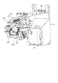
- the extractor 37 is what is called a so-called brewer unit, and extracts coffee from ground coffee beans fed from the grinder 33 via the powder chute 34 and hot water supplied by the hot water supply means 35. is there.
- a beverage supply line 38 is connected to such an extractor 37.
- the beverage supply line 38 is configured by a single beverage supply pipe or by connecting a plurality of beverage supply pipes, and supplies the coffee extracted by the extractor 37 to the nozzle 45.
- the beverage supply line 38 is provided with a first pinch valve 381 on the way.
- the first pinch valve 381 opens and closes in response to a command given from the control unit 60. When the first pinch valve 381 is opened, it allows the passage of fluid, and when it is closed, it passes the fluid. It regulates.
- the extractor 37 includes a cylinder 371, a lid 372, and a filter block 373.
- FIG. 9 and FIG. 10 are perspective views each showing a cylinder 371 constituting the extractor 37.
- the cylinder 371 has a substantially cylindrical shape, and is provided detachably with respect to the main body cabinet 10 (the apparatus main body 1).
- annular sealing materials 374 such as packings are respectively mounted on mounting recesses 371c and 371d formed on the opening edges of the upper surface opening 371a and the lower surface opening 371b. This seals the opening edge.
- such a sealing material 374 has a plurality of (for example, four) endless protruding pieces 374a formed on the inner peripheral surface thereof in a circumferential direction so as to be separated from each other.
- a locking projection 374b is formed on a part of the outer peripheral surface of the seal member 374 so as to project outward in the radial direction.
- the sealing member 374 abuts against the inner surfaces of the mounting recesses 371c and 371d while elastically deforming the projection 374a, and also engages with the locking holes 371c1 and 371d1 formed in the mounting recesses 371c and 371d.
- the locking projection 374b is inserted from the inside into the mounting recesses 371c and 371d to seal the opening edge.
- the lid 372 moves in a manner to approach or separate from the upper surface opening 371a of the cylinder 371 by, for example, driving a driving mechanism 372a such as a motor in accordance with a command given from the controller 60. 371a is opened and closed.
- the lid 372 has a hole for allowing ground coffee beans supplied through the powder chute 34 to be supplied to the cylinder 371, and hot water supplied by the hot water supply means 35 is supplied to the cylinder 371. Holes are formed to allow the holes to be removed.
- the filter block 373 is provided below the cylinder 371, and is connected to the beverage supply line 38.
- the filter block 373 moves up and down in a manner approaching and separating from the cylinder 371 by driving a motor 373 a in response to a command given from the control unit 60.
- such a filter block 373 is detachably provided in a filter storage section 47 attached to the main body cabinet 10. That is, the filter block 373 is detachably provided to the apparatus main body 1.
- the filter storage portion 47 rotatably supports and stores the filter roll FR around which the paper filter PF is wound.
- the filter storage unit 47 is provided with a rotation detection unit 471.
- the rotation detection unit 471 is configured by, for example, an encoder or the like, and is a rotation detection unit that detects rotation of the filter roll FR.
- the rotation detecting section 471 sends a rotation signal to the control section 60 when detecting the rotation of the filter roll FR.
- a groove 373b is formed at the rear end of the filter block 373, and a protrusion 472 formed in the filter housing 47 is inserted into the groove 373b and mounted on the apparatus main body 1.
- Such a filter block 373 is provided with a paper roller unit 375, a first cutter unit 376, and a second cutter unit 377, as shown in FIG.
- the paper roller unit 375 holds the paper filter PF that is pulled out from the filter roll FR and guided by the guide roller GR.
- the paper roller unit 375 rotates when an operation command is given from the control unit 60.
- the first cutter section 376 is provided below the paper roller section 375 to cut the paper filter PF.
- the first cutter portion 376 has a blade portion 376a for cutting the paper filter PF at a lower end edge portion, and is a portion extending along the vertical direction.
- the second cutter section 377 is provided on the rear side of the paper roller section 375, and is for cutting the paper filter PF.
- the second cutter portion 377 has a blade portion 377a for cutting the paper filter PF at an upper edge.
- such a filter block 373 is configured such that the paper filter PF drawn out from the filter roll FR passes between the cylinder 371 and the filter block 373 as shown by a broken line (a).
- the paper filter PF is set in a predetermined path, the paper filter PF is fed out from the filter roll FR by the rotation of the paper roller unit 375. That is, the paper roller unit 375 allows a feeding operation in which the paper filter PF can be fed from the filter roll FR.
- the paper filter PF pulled out from the filter roll FR is not set in a predetermined path as shown by the one-dot chain line (b) and the two-dot chain line (c), the following occurs. That is, when the paper filter PF is set as shown by the one-dot chain line (b), the displacement of the paper filter PF is regulated by the protrusion 472 inserted into the groove 373b. The feeding out of the paper filter PF is restricted. When the paper filter PF is set as shown by the two-dot chain line (c), the paper filter PF is cut into the second cutter 377 by the rotation of the paper roller 375, and the paper filter PF is fed out from the filter roll FR. Be regulated.
- the filter block 373 restricts the feeding of the paper filter PF when the paper filter PF is not set in a predetermined path.
- FIG. 19 is a plan view showing the storage box 39 shown in FIG.
- the storage box 39 is installed in a lower region of the extractor 37, and stores the extraction residue generated by extracting the beverage with the extractor 37 together with the paper filter PF.
- the storage box 39 includes a partition member 391, and is divided into an area 39a for storing the extracted slag and an area 39b for storing the paper filter PF by the partition member 391.
- the pressurized air supply line 41 is configured by connecting a plurality of pressurized air supply pipes. One end of the pressurized air supply line 41 is connected to the lid 372, and the other end is connected to the middle of the beverage supply line 38.
- the pressurized air supply line 41 is provided with an air pump 411, a second pinch valve 412, and a third pinch valve 413.
- the air pump 411 is driven in accordance with a command given from the control unit 60, and compresses and sends out air.
- the second pinch valve 412 is provided on one end side (the lid 372 side) of the air pump 411.
- the second pinch valve 412 opens and closes in response to a command given from the control unit 60, and allows passage of fluid when in an open state, and allows passage of fluid when in a closed state. It regulates.
- the third pinch valve 413 is provided on the other end side (the beverage supply line 38 side) of the air pump 411.
- the third pinch valve 413 opens and closes in response to a command given from the control unit 60, and allows passage of fluid when in an open state, and allows passage of fluid when in a closed state. It regulates.
- the drainage line 43 is configured by connecting one or more drainage pipes, and is provided so as to branch off from the middle of the beverage supply line 38.
- the drain line 43 is provided with a fourth pinch valve 431.
- the fourth pinch valve 431 opens and closes in response to a command given from the control unit 60, and allows passage of fluid when in an open state, and allows passage of fluid when in a closed state. It regulates.
- the nozzle 45 is detachable from the nozzle mounting portion 24 provided on the front door 20.
- the nozzle 45 is mounted on the nozzle mounting section 24 so as to face the beverage supply section 22, as shown in FIG. That is, the nozzle 45 is detachably provided so as to face the beverage supply unit 22.
- the nozzle 45 discharges the beverage supplied through the beverage supply line 38 to the container C mounted on the stage 22a.
- the nozzle 45 has a configuration in which the opening 451a is closed by a lid 452 with respect to a nozzle main body 451 having an opening 451a at an upper portion thereof.
- the beverage supply line 38 is connected so as to communicate with the hole 452a.
- a joint member 46 is provided at an end of the beverage supply line 38, and a light-shielding portion 461 is formed on the joint member 46.
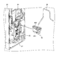
- the nozzle mounting section 24 is provided with a nozzle detecting section (detecting means) 25.
- the nozzle detection unit 25 is configured by a so-called optical sensor or the like.
- the nozzle detection unit 25 is turned on only when light emitted from a light emitting unit (not shown) is blocked by the light blocking unit 461 of the joint member 46 of the beverage supply line 38 connected to the nozzle 45, This is to detect that the nozzle 45 connected to the beverage supply line 38 is attached in a manner facing the beverage supply unit 22.
- the nozzle detection unit 25 gives the detection result to the control unit 60 as a signal.
- the nozzle body 451 has a discharge port 451b for discharging a beverage at a front part, and air supplied with the beverage is supplied to a rear part separated from the discharge port 451b. It has a discharge port 451c for discharging.
- the discharge port 451c is provided on the back surface of the front door 20 outside the beverage supply unit 22, as shown in FIGS. It faces the discharged discharge path 26.
- the discharge path 26 communicates with a drain tray 27 formed below the beverage supply unit 22.
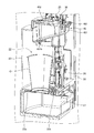
- a fan box 50 is provided in the main body cabinet 10 in a state adjacent to the beverage producing unit 30.
- the fan box 50 is for sucking the steam generated in the beverage producing unit 30 by the action of the exhaust fan F disposed at the left bottom portion inside the main body cabinet 10. And at the upper end of an exhaust path 55 formed between the two.
- the fan box 50 has a box-like shape, and has a filter opening 51 formed on the front surface thereof.
- a fan filter 52 is removably mounted through the filter opening 51. Things.
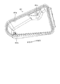
- a rail portion 53 is formed on the lower surface of the upper portion and the upper surface of the lower portion of the fan box 50 as shown in FIG.
- the rail portion 53 can guide the fan filter 52 that is being inserted or withdrawn while being partly curved so as to be inclined in the left-right direction.
- the control unit 60 controls the operation of each unit of the beverage supply apparatus according to programs and data stored in a storage unit (not shown).
- the control unit 60 may be realized by, for example, causing a processing device such as a CPU (Central Processing Unit) to execute a program, that is, realized by software, or realized by hardware such as an IC (Integrated Circuit). Alternatively, it may be realized by using software and hardware together.
- a processing device such as a CPU (Central Processing Unit) to execute a program, that is, realized by software, or realized by hardware such as an IC (Integrated Circuit). Alternatively, it may be realized by using software and hardware together.
- the control unit 60 includes a sales control unit 61 and a setting control unit 62.
- the sales control unit 61 controls the production and supply of the beverage in the beverage production unit 30.
- the setting control unit 62 determines whether or not the setting of the paper filter PF is normal, and performs a paper filter determination process described later.
- the coffee beverage can be supplied to the container C placed on the stage 22a of the beverage supply unit 22 as follows. It is assumed that hot water at a predetermined temperature is generated and stored in the hot water tank 351, and the third pinch valve 381, the second pinch valve 412, and the fourth pinch valve 431 are closed and the third pinch valve 431 is closed. It is assumed that the pinch valve 413 is in the open state.
- the sales control section 61 of the control section 60 to which the sales signal of the selected beverage is given turns the filter block 373 upward as shown in FIG.
- a drive command is given to the raw material supply driving unit 311 to pay out the coffee beans in an amount corresponding to the beverage to the crusher 33, and a drive command is given to the crusher 33 to crush and extract the coffee beans.
- Machine 37 After that, the driving of the raw material supply driving unit 311 is stopped. It is assumed that the beverage selected by the user has a supply amount to the container C equal to or larger than the capacity of the extractor 37 (cylinder 371).
- the sales control section 61 drives the metering pump 352 to send a fixed amount of hot water from the hot water tank 351 to the auxiliary tank 353, and also drives the hot water supply pump 354 to pressurize the hot water in the auxiliary tank 353 and send it to the extractor 37. Then, hot water is charged into the extractor 37. After that, the driving of the metering pump 352 and the hot water supply pump 354 is stopped.
- the sales control unit 61 drives the air pump 411 to use a part of the beverage supply line 38 to supply pressurized air (pressurized air for stirring) to the cylinder 371 as shown in FIG. It is supplied to stir (forced stirring) the ground coffee beans and hot water. After that, the driving of the air pump 411 is stopped.
- the sales control unit 61 having forcedly agitated the ground coffee beans and the hot water in this manner moves the lid 372 downward to close the upper opening 371a of the cylinder 371 and closes the third pinch valve 413. Then, the first pinch valve 381 and the second pinch valve 412 are opened, and the air pump 411 is driven. The fourth pinch valve 431 is kept closed.
- coffee is extracted by supplying pressurized air (pressurized air for extraction) to the cylinder 371, and the extracted coffee is fed to the nozzle 45 via the beverage supply line 38. It is supplied and discharged to the container C from the discharge port 451b of the nozzle 45.
- a discharge port 451c for discharging pressurized air supplied together with coffee through the beverage supply line 38 is separated from the discharge port 451b, and faces the discharge path 26 provided outside the beverage supply unit 22 at the nozzle 45. Since it is provided in a manner, the pressurized air can be discharged to the discharge path 26.
- the sales control unit 61 As described above, since the supply amount of the beverage selected by the user to the container C is equal to or larger than the capacity of the extractor 37 (cylinder 371), the sales control unit 61, as shown in FIG. While the coffee is being discharged from the container to the container C, the fixed-quantity pump 352 is driven to send a fixed amount of hot water from the hot water tank 351 to the auxiliary tank 353, and the hot-water supply pump 354 is driven to pressurize and extract the hot water in the auxiliary tank 353. Device 37.
- the hot water temporarily stored in the auxiliary tank 353 is sent out in a pressurized state to the extractor 37, and the coffee extracted using the hot water is discharged from the nozzle 45 to the container C, so that a predetermined amount of coffee is discharged.
- the sales control unit 61 stops driving the metering pump 352, the hot water supply pump 354, and the air pump 411. Thereby, the user can take out the container C from the beverage supply unit 22 by swinging the opening / closing door 23 in the opening direction.
- the sales control unit 61 releases the internal pressure of the cylinder 371 by moving the lid 372 upward to open the upper surface opening 371a of the cylinder 371. Then, the sales control unit 61 supplies hot water from the hot water supply means 35 to the extractor 37 to clean the inside of the cylinder 371, and opens the fourth pinch valve 431, and as shown in FIG. The water remaining in the extractor 37 is discharged via the.
- the sales control unit 61 that has discharged the water in this manner closes the fourth pinch valve 431, and moves the filter block 373 downward as shown in FIG. Then, the sales control unit 61 gives an operation command to the paper roller unit 375 to feed out the paper filter PF by a predetermined amount, and causes the extraction box generated by extracting the coffee beverage to be stored in the storage box 39 together with the paper filter PF, The supply of coffee this time ends.
- control unit 60 sales control unit 61 of the beverage supply device, when the supply amount of coffee to the container C is equal to or larger than the capacity of the extractor 37 (cylinder 371), controls the extractor 37 that is extracting coffee.
- the hot water is supplied by the hot water supply means 35.
- a cleaning operation and a rinsing operation for distributing only hot water to the beverage generating unit 30 are performed periodically. Then, when a sales signal is given after the cleaning operation or when the rinsing operation is performed, the setting control unit 62 of the control unit 60 performs the following paper filter before the supply of the beverage and the rinsing operation. Perform the judgment process.
- FIG. 33 is a flowchart showing the contents of a paper filter determination process performed by the setting control unit 62 shown in FIG.
- the setting control unit 62 sends an operation command to the paper roller unit 375 (step S101), and waits for input of a rotation signal from the rotation detection unit 471 (step S102).
- the filter block 373 is provided on the apparatus main body 1 so as to be detachable, and regulates the feeding of the paper filter PF when the paper filter PF is not set in a predetermined path.
- Step S102 when the rotation signal from the rotation detecting unit 471 is input (Step S102: Yes), the setting control unit 62 determines that the setting of the paper filter PF is normal (Step S103), and operates the paper roller unit 375. A stop command is sent (step S104), and thereafter, the procedure is returned to end the current processing.
- step S102 when the rotation signal is not input from the rotation detecting unit 471 even after the predetermined time has elapsed (step S102: No), the setting control unit 62 determines that the feeding of the paper filter PF is restricted. Assuming that the filter roll FR does not rotate, it is determined that the setting of the paper filter PF is abnormal (step S105), and a display command for displaying the occurrence of the abnormality on the display unit 21 is transmitted (step S106). Then, the setting control unit 62 sends an operation stop command to the paper roller unit 375 (step S107), and thereafter returns the procedure to end the current process.
- the nozzle detection unit 25 detects that the nozzle 45 connected to the beverage supply line 38 is mounted in a manner facing the beverage supply unit 22, the nozzle 45 is not sufficiently connected to the beverage supply line 38. It is possible to avoid being mounted in a state facing the beverage supply unit 22 as it is, and it is possible to prevent coffee (beverage) from leaking due to the connection between the nozzle 45 and the beverage supply line 38.
- the discharge port 451c of the nozzle 45 is separated from the discharge port 451b and faces the discharge path 26 provided outside the beverage supply unit 22, the pressurized air supplied together with the coffee is discharged. It can be discharged to the passage 26 and can be prevented from being discharged to the container C, and the risk of foreign matter entering the container C can be reduced.
- the rail portion 53 formed on the fan box 50 guides the fan filter 52 in the middle of insertion or withdrawal in a posture inclined in the left-right direction. Regardless, the fan filter 52 can be easily inserted into and removed from the fan box 50.
- the storage box 39 is divided into a region 39a for storing the extraction residue by the partition member 391 and a region 39b for storing the paper filter PF, the extraction residue and the paper filter PF can be easily separated. Can be.
- the leaf spring 323 interposed between the raw material chute 32 and the pulverizer 33 urges the raw material chute 32 in a mode in which the raw material chute 32 is separated from the pulverizer 33 and is close to the raw material box 31. Even if the installation height of the crusher 33 varies, the raw material chute 32 can be pressed against the raw material box 31, and the connection between the raw material box 31 and the crusher 33 can be improved.
- the gutter 312 provided integrally with the raw material box 31 receives the liquid that has entered through the gap 13 in the top plate portion 12 of the main body cabinet 10 and guides the liquid to a region outside the beverage producing unit 30. It is possible to prevent the beverage from dropping into the beverage generation unit 30.
- the controller 60 (sales controller 61) supplies hot water to the extractor 37 that is extracting coffee by the hot water supply means 35. Since it is added, the supply time of coffee can be shortened in contrast to the conventional method of supplying hot water and stirring.
- the cylinder 371 constituting the extractor 37 is configured such that the opening edges of the upper surface opening 371a and the lower surface opening 371b are sealed by the sealing material 374, so that there is no need to remove the sealing material from the lid as in the related art.
- the cleaning operation of the extractor 37 can be simplified.
- the sealing material 374 abuts against the inner surfaces of the mounting recesses 371c and 371d while elastically deforming the projection 374a, even if the pressure inside the cylinder 371 increases during coffee extraction or the like, the mounting recess 371c, The state of being attached to the 371d can be maintained, and the pressure resistance can be improved.
- the sealing material 374 is attached to the mounting recesses 371c and 371d by inserting the locking projections 374b into the locking holes 371c1 and 371d1 from the inside.
- the seal member 374 can be easily removed from the mounting recesses 371c and 371d by being separated from the mounting recesses 371c and 371d.
- the metering pump 352 sends a fixed amount of hot water from the hot water tank 351 to the auxiliary tank 353, and the hot water pump 354 pressurizes the hot water in the auxiliary tank 353 and sends it to the extractor 37. Even when the hot water is pressurized, a predetermined amount can be satisfactorily supplied.
- the filter block 373 restricts the feeding of the paper filter PF when the paper filter PF is not set in a predetermined path.
- the rotation detecting unit 471 detects the rotation of the filter roll FR, it is determined that the setting of the paper filter PF is normal, while the rotation detecting unit 471 detects the rotation of the filter.
- the setting of the paper filter PF is determined to be abnormal, so that the setting of the paper filter PF can be determined satisfactorily.
- the first cutter portion 376 constituting the filter block 373 extends in the vertical direction, it is possible to suppress the accumulation of ground coffee beans and the like on the first cutter portion 376.
- the nozzle detection unit 25 is turned on and connected to the beverage supply line 38 only when the light emitted from the light emitting unit is blocked by the light blocking unit 461 of the joint member 46.
- a light shielding unit may be provided in the nozzle.
- the end of the beverage supply line provided with the joint member is always connected to the nozzle mounting portion, and when the nozzle is mounted on the nozzle mounting portion, the joint member engages with the nozzle and the light shielding portion of the nozzle. May block the light of the detection means.
- the form is not particularly limited as long as the detecting means can detect that the nozzle connected to the beverage supply line is attached in a manner facing the beverage supply unit.
- the storage box 39 is divided into the region 39a for storing the extracted slag by the partition member 391 and the region 39b for storing the paper filter PF.
- the region 39a for storing the extracted slag by the partition member 391 There is no particular limitation on the form, and by installing a small box for storing the paper filter inside the storage box, it is divided into a region for storing the extraction slag and a region for storing the paper filter. May be configured.
- the gutter 312 is provided integrally with the raw material box 31.
- the place where the gutter member is installed is not particularly limited.
- the gutter member is hung on the top plate of the main body cabinet. It may be provided in an aspect.
- the present invention may be configured as follows. That is, the speed of supplying hot water to the extractor by the hot water supply means may be changed according to the type of beverage to be supplied. Thereby, the degree of stirring between the raw material and the hot water can be changed, and the taste of the beverage to be extracted can be adjusted. Further, in the present invention, the hot water supply means may be configured to supply hot water by rotating the hot water in such a manner as to contact the inner wall surface of the cylinder. Thereby, the hot water can be stirred with the whole raw material charged into the extractor.
- the fixed amount pump 352 sends the fixed amount of hot water from the hot water tank 351 to the auxiliary tank 353.
- the fixed amount pump is not limited to the fixed amount pump and is configured by a valve or the like. Is also good. That is, a fixed amount of hot water may be sent to the auxiliary tank by opening the valve continuously for a predetermined time.
- the material of the filter block 373 is not particularly described, but in the present invention, the filter block may be made of a resin material in which an antibacterial material is appropriately mixed. Thereby, propagation of various bacteria can be suppressed.
- the display unit 21 displays that an abnormality has occurred. If it is determined that the filter set is abnormal, an alarm such as a buzzer sound may be output by the notification unit to urge the worker such as an employee of the store to reset the paper filter.
- refilling of the filter roll into the filter storage portion may be performed from the front or from behind.
- SYMBOLS 1 Device main body, 10 ... Main body cabinet, 20 ... Front door, 22 ... Beverage supply part, 30 ... Beverage production part, 31 ... Raw material box, 33 ... Crusher, 35 ... Hot water supply means, 37 ... Extractor, 39 ... Housing Box, 41: Pressurized air supply line, 43: Drain line, 45: Nozzle, 50: Fan box, 60: Control unit, C: Container, FR: Filter roll, PF: Paper filter.
Landscapes
- Engineering & Computer Science (AREA)
- Food Science & Technology (AREA)
- Physics & Mathematics (AREA)
- General Physics & Mathematics (AREA)
- Apparatus For Making Beverages (AREA)
Abstract
L'invention concerne un appareil de distribution de boisson comprenant une unité de commande (60) destinée à entraîner l'acheminement d'air sous pression pour l'agitation vers une machine d'extraction (37) dans laquelle est introduite une matière première broyée par une machine de broyage (33) et dans laquelle est acheminée de l'eau chaude par un moyen d'alimentation en eau chaude (35) de sorte à entraîner l'agitation de la matière première et de l'eau chaude, l'unité de commande entraînant l'acheminement d'air sous pression à extraire vers la machine d'extraction (37), après l'agitation, de sorte à provoquer l'extraction d'une boisson, puis l'appareil de distribution de boisson acheminant la boisson extraite par la machine d'extraction (37) vers un récipient C. Lorsque la quantité de boisson distribuée dans le récipient C est supérieure ou égale à la capacité volumétrique de la machine d'extraction (37), l'unité de commande (60) entraîne l'ajout d'eau chaude par le moyen d'alimentation en eau chaude (35) à ladite machine (37) pendant l'extraction de la boisson.
Priority Applications (3)
| Application Number | Priority Date | Filing Date | Title |
|---|---|---|---|
| CN201980051904.8A CN112533515B (zh) | 2018-09-14 | 2019-09-02 | 饮料供给装置 |
| KR1020217003218A KR102480177B1 (ko) | 2018-09-14 | 2019-09-02 | 음료 공급 장치 |
| US17/159,757 US12048392B2 (en) | 2018-09-14 | 2021-01-27 | Beverage supply apparatus |
Applications Claiming Priority (6)
| Application Number | Priority Date | Filing Date | Title |
|---|---|---|---|
| JP2018173088A JP6702381B2 (ja) | 2018-09-14 | 2018-09-14 | 飲料供給装置 |
| JP2018-173088 | 2018-09-14 | ||
| JP2018173098A JP6702382B2 (ja) | 2018-09-14 | 2018-09-14 | 飲料供給装置 |
| JP2018-173098 | 2018-09-14 | ||
| JP2018-174284 | 2018-09-18 | ||
| JP2018174284A JP6702383B2 (ja) | 2018-09-18 | 2018-09-18 | 飲料供給装置 |
Related Child Applications (1)
| Application Number | Title | Priority Date | Filing Date |
|---|---|---|---|
| US17/159,757 Continuation US12048392B2 (en) | 2018-09-14 | 2021-01-27 | Beverage supply apparatus |
Publications (1)
| Publication Number | Publication Date |
|---|---|
| WO2020054488A1 true WO2020054488A1 (fr) | 2020-03-19 |
Family
ID=69777588
Family Applications (1)
| Application Number | Title | Priority Date | Filing Date |
|---|---|---|---|
| PCT/JP2019/034484 Ceased WO2020054488A1 (fr) | 2018-09-14 | 2019-09-02 | Appareil de distribution de boisson |
Country Status (4)
| Country | Link |
|---|---|
| US (1) | US12048392B2 (fr) |
| KR (1) | KR102480177B1 (fr) |
| CN (1) | CN112533515B (fr) |
| WO (1) | WO2020054488A1 (fr) |
Families Citing this family (3)
| Publication number | Priority date | Publication date | Assignee | Title |
|---|---|---|---|---|
| JP7501378B2 (ja) * | 2021-01-08 | 2024-06-18 | 富士電機株式会社 | 飲料供給装置 |
| JP1748599S (ja) * | 2023-01-25 | 2023-07-13 | 飲料供給機 | |
| TWI852514B (zh) * | 2023-04-27 | 2024-08-11 | 日商富士電機股份有限公司 | 飲料供給裝置 |
Citations (8)
| Publication number | Priority date | Publication date | Assignee | Title |
|---|---|---|---|---|
| JPS59147283U (ja) * | 1983-03-18 | 1984-10-02 | 東芝機器株式会社 | 自動販売機の温水供給制御装置 |
| JPH113466A (ja) * | 1997-06-13 | 1999-01-06 | Matsushita Refrig Co Ltd | 抽出装置 |
| JP2008168113A (ja) * | 2006-12-15 | 2008-07-24 | Fuji Electric Retail Systems Co Ltd | 飲料抽出装置およびこれを備えた飲料供給装置 |
| JP2008281110A (ja) * | 2007-05-10 | 2008-11-20 | Nok Corp | 密封構造 |
| JP2010179093A (ja) * | 2009-01-09 | 2010-08-19 | Fuji Electric Retail Systems Co Ltd | 飲料抽出装置のペーパーフィルタ送出し装置 |
| JP2011033082A (ja) * | 2009-07-30 | 2011-02-17 | Toyoda Gosei Co Ltd | シール構造 |
| JP2012142025A (ja) * | 2006-06-13 | 2012-07-26 | Fuji Electric Retail Systems Co Ltd | 飲料抽出装置 |
| WO2016132412A1 (fr) * | 2015-02-18 | 2016-08-25 | パナソニックIpマネジメント株式会社 | Dispositif de fourniture de boissons |
Family Cites Families (29)
| Publication number | Priority date | Publication date | Assignee | Title |
|---|---|---|---|---|
| US3379116A (en) * | 1966-05-31 | 1968-04-23 | Columware Inc | Beverage or food dispenser |
| US5083504A (en) * | 1989-03-27 | 1992-01-28 | Sanyo Electric Co., Ltd. | Drink extraction apparatus |
| DE4212288A1 (de) * | 1992-04-11 | 1993-10-14 | Braun Ag | Brüheinrichtung für eine Haushalts-Espressomaschine |
| JPH09327389A (ja) * | 1996-06-11 | 1997-12-22 | Sanden Corp | コーヒー抽出装置及びコーヒー抽出方法 |
| JPH09327385A (ja) * | 1996-06-11 | 1997-12-22 | Sanden Corp | コーヒー抽出装置 |
| US6079317A (en) * | 1998-12-15 | 2000-06-27 | Sanyo Electric Co., Ltd. | Beverage extraction apparatus |
| JP3852656B2 (ja) * | 1999-11-26 | 2006-12-06 | 富士電機リテイルシステムズ株式会社 | 炭酸飲料供給装置 |
| JP2004194719A (ja) * | 2002-12-16 | 2004-07-15 | Eiken Industries Co Ltd | 調理装置 |
| JP2004246616A (ja) * | 2003-02-13 | 2004-09-02 | Fuji Electric Retail Systems Co Ltd | 飲料自動販売機 |
| US20050193891A1 (en) * | 2004-03-08 | 2005-09-08 | Brent Garson | Espresso making apparatus and method of brewing espresso |
| JP2006190238A (ja) | 2004-12-07 | 2006-07-20 | Fuji Electric Retail Systems Co Ltd | 飲料抽出装置および飲料抽出方法 |
| FR2896676B1 (fr) * | 2006-02-01 | 2011-07-01 | Nielsen Innovation | Appareil destine a confectionner une infusion de the ou de cafe |
| US9993105B2 (en) * | 2008-05-01 | 2018-06-12 | Bunn-O-Matic Corporation | Method of making a beverage with a controllable brewer |
| US8286547B1 (en) * | 2008-05-23 | 2012-10-16 | Food Equipment Technologies Company, Inc. | Automated french press-like quality producing, high volume, automated, electric beverage maker |
| JP4692638B2 (ja) * | 2009-01-09 | 2011-06-01 | 富士電機リテイルシステムズ株式会社 | 飲料調理装置およびこれを備えた飲料提供装置 |
| DE202009014945U1 (de) * | 2009-08-05 | 2010-09-23 | Nestec S.A. | Kapsel mit reliefförmigen Dichtungselement |
| US9295358B2 (en) * | 2009-10-28 | 2016-03-29 | Bkon Llc | Vacuum brewed beverage machine and vacuum brewing method |
| CN102160746B (zh) * | 2011-01-27 | 2014-04-02 | 苏州工业园区咖乐美电器有限公司 | 咖啡机的冲泡装置 |
| CN203354228U (zh) * | 2013-06-28 | 2013-12-25 | 淮安龙之梦科技有限公司 | 一种两端拆装的滤茶杯 |
| JP6402423B2 (ja) * | 2014-06-25 | 2018-10-10 | サンデンホールディングス株式会社 | 飲料供給装置 |
| JP6449596B2 (ja) * | 2014-08-29 | 2019-01-09 | サンデンホールディングス株式会社 | 飲料供給装置 |
| US9980602B2 (en) * | 2015-02-04 | 2018-05-29 | Hamilton Beach Brands, Inc. | Beverage maker |
| KR102449928B1 (ko) * | 2015-02-19 | 2022-09-30 | 로버트 알름블라드 | 자동화된 커피 및 차 메이커와 자동화된 압력 브루어 |
| ITUB20156010A1 (it) * | 2015-11-30 | 2017-05-30 | Amici Caffe Ag | Metodo e macchina per la preparazione di bevande |
| US10779675B2 (en) * | 2015-12-07 | 2020-09-22 | Bunn-O-Matic Corporation | Brewer system, method and apparatus |
| US20170303712A1 (en) * | 2016-04-25 | 2017-10-26 | Arie Pisarevsky | Portable capsule percolator drinking cup |
| CN109414134A (zh) * | 2016-06-27 | 2019-03-01 | 沙克忍者运营有限责任公司 | 自动咖啡机以及制备冲泡饮料的方法 |
| CN206518464U (zh) * | 2016-12-02 | 2017-09-26 | 苏州源德侬电器科技有限公司 | 咖啡胶囊壳 |
| CN207101133U (zh) * | 2017-02-27 | 2018-03-16 | 深圳前海小智萌品科技有限公司 | 冲调漏斗组件和冲奶机 |
-
2019
- 2019-09-02 KR KR1020217003218A patent/KR102480177B1/ko active Active
- 2019-09-02 CN CN201980051904.8A patent/CN112533515B/zh active Active
- 2019-09-02 WO PCT/JP2019/034484 patent/WO2020054488A1/fr not_active Ceased
-
2021
- 2021-01-27 US US17/159,757 patent/US12048392B2/en active Active
Patent Citations (8)
| Publication number | Priority date | Publication date | Assignee | Title |
|---|---|---|---|---|
| JPS59147283U (ja) * | 1983-03-18 | 1984-10-02 | 東芝機器株式会社 | 自動販売機の温水供給制御装置 |
| JPH113466A (ja) * | 1997-06-13 | 1999-01-06 | Matsushita Refrig Co Ltd | 抽出装置 |
| JP2012142025A (ja) * | 2006-06-13 | 2012-07-26 | Fuji Electric Retail Systems Co Ltd | 飲料抽出装置 |
| JP2008168113A (ja) * | 2006-12-15 | 2008-07-24 | Fuji Electric Retail Systems Co Ltd | 飲料抽出装置およびこれを備えた飲料供給装置 |
| JP2008281110A (ja) * | 2007-05-10 | 2008-11-20 | Nok Corp | 密封構造 |
| JP2010179093A (ja) * | 2009-01-09 | 2010-08-19 | Fuji Electric Retail Systems Co Ltd | 飲料抽出装置のペーパーフィルタ送出し装置 |
| JP2011033082A (ja) * | 2009-07-30 | 2011-02-17 | Toyoda Gosei Co Ltd | シール構造 |
| WO2016132412A1 (fr) * | 2015-02-18 | 2016-08-25 | パナソニックIpマネジメント株式会社 | Dispositif de fourniture de boissons |
Also Published As
| Publication number | Publication date |
|---|---|
| US20210145204A1 (en) | 2021-05-20 |
| CN112533515B (zh) | 2023-12-15 |
| KR102480177B1 (ko) | 2022-12-21 |
| CN112533515A (zh) | 2021-03-19 |
| KR20210025648A (ko) | 2021-03-09 |
| US12048392B2 (en) | 2024-07-30 |
Similar Documents
| Publication | Publication Date | Title |
|---|---|---|
| WO2020054488A1 (fr) | Appareil de distribution de boisson | |
| JP6635162B1 (ja) | 飲料供給装置 | |
| JP6635161B1 (ja) | 飲料供給装置 | |
| JP7443773B2 (ja) | 飲料供給装置 | |
| JP6702381B2 (ja) | 飲料供給装置 | |
| JP6702382B2 (ja) | 飲料供給装置 | |
| WO2020054482A1 (fr) | Dispositif de distribution de boisson | |
| JP6702383B2 (ja) | 飲料供給装置 | |
| JP2020043932A (ja) | 飲料供給装置 | |
| CN114747938B (zh) | 饮料供给装置 | |
| JP2020043933A (ja) | 飲料供給装置 | |
| JP2020043934A (ja) | 飲料供給装置 | |
| JP7509325B1 (ja) | 飲料供給装置 | |
| WO2024161693A1 (fr) | Dispositif de distribution de boisson | |
| JP2021180713A (ja) | 飲料供給装置 | |
| JP2022107389A (ja) | 飲料供給装置 | |
| JP7414098B1 (ja) | 飲料供給装置 | |
| JP2021108958A (ja) | 飲料供給装置 | |
| JP2021145772A (ja) | 飲料供給装置 | |
| JP2023172232A (ja) | 飲料供給装置 | |
| CN111065300A (zh) | 饮料供给装置 |
Legal Events
| Date | Code | Title | Description |
|---|---|---|---|
| 121 | Ep: the epo has been informed by wipo that ep was designated in this application |
Ref document number: 19860356 Country of ref document: EP Kind code of ref document: A1 |
|
| ENP | Entry into the national phase |
Ref document number: 20217003218 Country of ref document: KR Kind code of ref document: A |
|
| NENP | Non-entry into the national phase |
Ref country code: DE |
|
| 122 | Ep: pct application non-entry in european phase |
Ref document number: 19860356 Country of ref document: EP Kind code of ref document: A1 |