WO2020090370A1 - 既設構造物の補強装置および付帯設備取付装置 - Google Patents
既設構造物の補強装置および付帯設備取付装置 Download PDFInfo
- Publication number
- WO2020090370A1 WO2020090370A1 PCT/JP2019/039570 JP2019039570W WO2020090370A1 WO 2020090370 A1 WO2020090370 A1 WO 2020090370A1 JP 2019039570 W JP2019039570 W JP 2019039570W WO 2020090370 A1 WO2020090370 A1 WO 2020090370A1
- Authority
- WO
- WIPO (PCT)
- Prior art keywords
- band
- angle
- angle member
- tightening
- members
- Prior art date
- Legal status (The legal status is an assumption and is not a legal conclusion. Google has not performed a legal analysis and makes no representation as to the accuracy of the status listed.)
- Ceased
Links
Images


Classifications
-
- E—FIXED CONSTRUCTIONS
- E04—BUILDING
- E04H—BUILDINGS OR LIKE STRUCTURES FOR PARTICULAR PURPOSES; SWIMMING OR SPLASH BATHS OR POOLS; MASTS; FENCING; TENTS OR CANOPIES, IN GENERAL
- E04H12/00—Towers; Masts or poles; Chimney stacks; Water-towers; Methods of erecting such structures
- E04H12/24—Cross arms
-
- E—FIXED CONSTRUCTIONS
- E04—BUILDING
- E04G—SCAFFOLDING; FORMS; SHUTTERING; BUILDING IMPLEMENTS OR AIDS, OR THEIR USE; HANDLING BUILDING MATERIALS ON THE SITE; REPAIRING, BREAKING-UP OR OTHER WORK ON EXISTING BUILDINGS
- E04G23/00—Working measures on existing buildings
- E04G23/02—Repairing, e.g. filling cracks; Restoring; Altering; Enlarging
- E04G23/0218—Increasing or restoring the load-bearing capacity of building construction elements
-
- E—FIXED CONSTRUCTIONS
- E04—BUILDING
- E04G—SCAFFOLDING; FORMS; SHUTTERING; BUILDING IMPLEMENTS OR AIDS, OR THEIR USE; HANDLING BUILDING MATERIALS ON THE SITE; REPAIRING, BREAKING-UP OR OTHER WORK ON EXISTING BUILDINGS
- E04G23/00—Working measures on existing buildings
- E04G23/02—Repairing, e.g. filling cracks; Restoring; Altering; Enlarging
-
- E—FIXED CONSTRUCTIONS
- E04—BUILDING
- E04H—BUILDINGS OR LIKE STRUCTURES FOR PARTICULAR PURPOSES; SWIMMING OR SPLASH BATHS OR POOLS; MASTS; FENCING; TENTS OR CANOPIES, IN GENERAL
- E04H12/00—Towers; Masts or poles; Chimney stacks; Water-towers; Methods of erecting such structures
- E04H12/02—Structures made of specified materials
- E04H12/08—Structures made of specified materials of metal
- E04H12/10—Truss-like structures
Definitions
- the present invention provides a reinforcing device for an existing structure that can be reinforced by attaching it to an angle member that constitutes the existing structure, and an auxiliary device such as an antenna or a lightning rod can be attached to the existing structure such as a steel tower.
- the present invention relates to equipment installation devices.
- Structures such as steel towers and buildings are made of angled materials and other shaped steel, and due to various factors such as earthquakes and weather, the angled materials and shaped steel are deformed, buckled, and deteriorated over time.
- a reinforcing device that reinforces such an existing structure there is Japanese Patent No. 6301212 “Reinforcing device for an existing steel structure” of the applicant.
- Patent Document 1 uses a parallel type angle steel assembly in which a first angle steel material and a second angle steel material are combined so that one sides of both angle steel materials are arranged in parallel in close proximity to each other. A reinforcing device for an existing steel frame structure configured as described above is described.
- the device described in Patent Document 1 has a width larger than the width of both sides of the first chevron steel material, and one end edge in the width direction abuts the inner corner of the first chevron steel material and the opening formed by both sides.
- the first reinforcing plate member is arranged so as to be positioned in the middle where the angle is divided into two and extends over the entire length in the length direction of the first angle steel member, and the width is larger than the width of both sides of the second angle steel member. Then, one end edge in the width direction abuts on the inner corner of the second angle steel and is positioned in the middle where the angle of the opening formed by both sides is divided into two, so that the entire length in the length direction of the second angle steel is obtained.
- the second reinforcing plate member extending over the first and second chevron steel members is integrally fixed to the first chevron steel member at a plurality of positions in the longitudinal direction of the first and second chevron steel members, and the second reinforcing plate member is A plurality of fixing mechanisms for integrally fixing the two angle steel materials, and the fixing mechanism is provided for the first and second angle steel materials.
- Supporting plate member arranged so as to penetrate through a gap formed between the two sides and extend in a direction orthogonal to the longitudinal direction of the first and second angle steel materials, and project outside the first angle steel material.
- First and second fixing fittings each having one end fixed to the tip of the first reinforcing plate by the first fixing bolts and nuts, and the tip of the second reinforcing plate protruding outside the second chevron steel.
- Third and fourth fixing fittings one ends of which are respectively fixed by second fixing bolts and nuts, and supports protruding outward from a gap formed between the other sides of the first and second angle steel materials.
- the first tightening bolt / nut for press-contacting the inner corner of the second chevron material, the other end of the second fixing member and the other end of the fifth fixing member are arranged to face each other, and both ends are close to each other.
- Patent Document 2 is an auxiliary equipment attaching device for attaching an auxiliary equipment to an angle material having a L-shaped cross section that constitutes a building, and includes a fixture for fixing the auxiliary equipment to the angle material,
- the fixture includes two band members arranged so as to sandwich both sides of the angle member from the respective outer side surfaces, and an inner side of the angle member so as to bisect an angle formed by both sides of the angle member inside the angle member.
- a band auxiliary member arranged to extend in a direction away from a corner, an extending end of the band auxiliary member protruding from the angle member, and a coupling bolt / nut for connecting one end of each band member.
- auxiliary equipment attaching device which has a support body provided at an end and to which an auxiliary equipment is attached.
- the first to sixth fixing brackets are used to fix the first to third fixing bolts and nuts and the first to third tightening bolts. It is fixed using a nut.
- the 1st to 3rd fixing bolts / nuts and the 1st to 3rd tightening bolts / nuts are attached to each two places, and the holding force and stability when the reinforcing device is attached to the angle steel Although it is expensive, the weight of the reinforcing device itself is heavy and the number of parts is large.
- the incidental equipment attachment device described in Patent Document 2 attaches importance to the holding force and stability when the device is attached to the angle member. Therefore, as shown in FIGS. -The two nuts are used for fixing, but the distance between the two bolts is also required, so the width of the band member becomes large and the device itself becomes heavy.
- the present invention has been made to solve the above-mentioned conventional problems, and is a reinforcement device for an existing structure that can be easily attached to an angle member that constitutes the existing structure, and an antenna or a lightning rod. It is an object of the present invention to provide an incidental equipment attaching device that can attach incidental equipment such as.
- the reinforcing device for an existing structure is configured by using an angle member having both sides having an L-shaped cross section, and the reinforcing device holds both sides of the angle member from the outer surface side of each.
- Two band members that are arranged, and a band auxiliary member that is arranged so as to divide the angle formed by both sides of the angle member inside the angle member so as to bisect from the inside corner of the angle member.
- the connecting bolt / nut and the tightening bolt / nut are the one end of the band member and the other.
- reinforcing ribs are provided on the outer surface of the band member. The reinforcing ribs are provided on either the upper part or the lower part, and when the two band members are combined and attached to the angle member, the reinforcing ribs of the two band members are located on vertically different sides. It is characterized by that.
- the end portion of the band auxiliary member has a width and the angle member is pressed from the inside, so that the angle member and the band member can be fixed more closely. It was found that even one each of the coupling bolt / nut and the tightening bolt / nut can be sufficiently fixed. Therefore, in the present invention, the connecting bolts and nuts and the tightening bolts and nuts are not arranged to be arranged in plural sets at one end and the other end of the band member, and only one set is arranged respectively. It was done.
- reinforcing ribs may be provided on the outer surface of the band member.
- the reinforcing ribs are provided on either the upper part or the lower part of the two band members, and when the two band members are combined and attached to the angle member, the reinforcing ribs of the two band members are on different sides from each other. It may be located.
- Reinforcing ribs may be provided on both upper and lower sides of the band member, but it was found that it is sufficiently strong if it is provided on only one of the upper and lower parts. If the reinforcing ribs are provided on only one side of the band member, the labor for manufacturing the reinforcing device itself is saved and the weight of the device itself is reduced. By reducing the distance between the bolt and the rib plate, the deformation can be suppressed to be small. By alternately arranging the reinforcing ribs, the balance of crimpability to the angle member is maintained.
- Each band member has a length larger than the width of one side, and is joined to the extending end of the band auxiliary member by a bolt / nut for joining with a holding part that is slidably contacted with the outer surface of the one side.
- the other end of each band member that is fastened in the direction serves as a fastening portion.
- the reinforcing rib is composed of a part that extends over the connecting part and the connecting part, and a part that extends over the sandwiching part and the tightening part.
- one of the band members may be bent so that the longitudinal end of the band member covers the longitudinal end of the other band member.
- the rotation of the device itself can be suppressed, and the movement of the angle member in the longitudinal direction can be converged.
- the joining bolt and the tightening bolt may be welded to the band member in advance.
- bolts are passed through the bolt holes on site and tightened with nuts, but especially when working in high places, it is not easy to tighten the nuts while fixing the bolts with a wrench, and in terms of safety, it may drop or fall. High risk.
- the nut side can be tightened and fixed with a single spanner, and the mounting work can be completed easily.
- An incidental equipment attaching device is for attaching an incidental equipment to an angle member having both sides having a L-shaped cross section that constitutes a structure, and is provided with a fixture for fixing the incidental equipment to the angle member,
- the fixture includes two band members arranged so as to sandwich both sides of the angle member from the respective outer side surfaces, and an inner side of the angle member so as to bisect an angle formed by both sides of the angle member inside the angle member.
- a band auxiliary member arranged to extend in a direction away from a corner, an extending end of the band auxiliary member protruding from the angle member, and a coupling bolt / nut for connecting one end of each band member.
- the outer corners formed by both sides of the angle member are tightened in the direction in which the other ends of the band members approach each other so that each band member does not slide along the outer surface of the side of the angle member.
- the tightening bolts and nuts that move to the outer corner side and press the edge of the band auxiliary member to the inner corner of the angle member to integrally fix the band auxiliary member to the angle member, and the extension of the band auxiliary member.
- an accessory installation device having a support body provided at an end portion and attached with accessory equipment, a plurality of coupling bolts and nuts and tightening bolts and nuts are arranged at one end and the other end of the band member, respectively.
- a reinforcing rib is provided on the outer surface of the band member, and the reinforcing rib is provided on either one of the upper part and the lower part of the two band members.
- the reinforcing ribs are located on the sides where the reinforcing ribs of the two band members are vertically different from each other when the two band members are combined and attached to the angle member. It is characterized in that so.
- each band member of the accessory installation device is also provided with a band auxiliary member, so that the end portion of the band auxiliary member has a width and the angle member is pressed from the inside. It was found that even one fastening bolt / nut and one fastening bolt / nut can be adequately secured because they can be fixed more closely. Therefore, the connecting bolts and nuts and the tightening bolts and nuts are not arranged to be arranged in plural sets at one end and the other end of the band member, but only one set is arranged. is there.
- reinforcing ribs may be provided on the outer surface of the band member. Further, the reinforcing ribs are provided on either the upper part or the lower part of the two band members, and when the two band members are combined and attached to the angle member, the reinforcing ribs of the two band members are vertically different from each other. It is good to be located on the side.
- the reinforcing ribs may be provided on both the upper and lower sides, but if they are provided on one of the upper and lower sides and the reinforcing ribs are alternately provided on the angle member, the strength is sufficient.
- each band member of the accessory installation device also has a length larger than the width of one side and a sandwiching part that is in sliding contact with the outer surface of the one side, and the extending end of the band auxiliary member.
- the reinforcing rib may be composed of a portion that extends over the connecting portion and the connecting portion and a portion that extends over the holding portion and the tightening portion.
- the reinforcing rib may include the connecting portion, the connecting portion, and the holding portion and the holding portion. The strength of the part is increasing.
- one of the band members may be bent so that the end of the other band member in the longitudinal direction covers the end of the other band member in the longitudinal direction.
- the connecting bolts and tightening bolts of the accessory equipment mounting device may be welded to the band member in advance.
- the existing structure reinforcing device and incidental equipment attaching device according to the present invention are configured as described above, and the following effects can be obtained.
- the reinforcing rib is only on one side, so that the tightening device can be easily inserted and fixed.
- the width of the band member can be narrowed and the number of reinforcing ribs and the number of bolts can be reduced as compared with the conventional product, the weight of the device itself can be reduced.
- FIG. 6 shows a front view in the embodiment of FIG. 5.
- FIG. 6 shows a side view of the embodiment of FIG. 5. It is the front view and side view which showed the band auxiliary member in the embodiment of FIG.
- FIG. 1 It is a one part schematic perspective view which shows one Embodiment at the time of applying the reinforcement apparatus which concerns on this invention to the truss structure which is an existing steel frame structure (2nd Embodiment). It is a one part schematic perspective view which showed another embodiment different from the embodiment of FIG. It is an expansion perspective view which expanded a part of embodiment of FIGS. It is a schematic explanatory drawing which shows an example in case the lightning rod is attached to the existing steel tower for antennas using the incidental equipment attachment apparatus which concerns on this invention (3rd Embodiment). It is a front view which shows the incidental equipment attachment device at the time of attaching a lightning rod to the angle material which comprises the steel tower for antennas shown in FIG. FIG.
- FIG. 14 is a plan view of the incidental equipment attachment device taken along the line AA of FIG. 13.
- FIG. 14 is a plan view of the incidental equipment attaching device taken along the line BB of FIG. 13.
- FIG. 14 is an exploded perspective view of a part of the accessory installation device shown in FIG. 13.
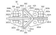
- the reinforcing device 30 includes a first band member 301 and a second band member 302, which are symmetrically arranged so as to sandwich both sides of the angle member 12 from the outer surface sides thereof, a band auxiliary member 303, and a pair of couplings. Bolt and nut 304 and a set of tightening bolts and nuts 305.
- the first band member 301 and the second band member 302 correspond to the two band members in the claims.
- the first band member 301 is made of a steel plate material, and is arranged to extend in a direction orthogonal to the width direction of the one side 121 so as to contact the outer surface of the one side 121 of the angle member 12.
- the first holding part 3011 having a length larger than the width of the one side 121 and press-contacted to the outer surface of the one side 121 of the angle member 12 and one end of the first holding part 3011.
- a first connecting portion 3012 obliquely provided to one end of the auxiliary member 303, and a first connecting portion provided at the tip of the first connecting portion 3012 and connected to one end of the band auxiliary member 303.
- 3013 and a first tightening portion 3014 that is provided at the end of the first sandwiching portion 3011 opposite to the first connecting portion 3012 and that generates a tightening force on the first band member 301.
- a reinforcing rib 3015 is provided between the first connecting portion 3012 and the first connecting portion 3013 at the connecting portion between the first connecting portion 3012 and the first connecting portion 3013. It is provided in.
- a reinforcing rib 3016 is provided between the first holding portion 3011 and the first tightening portion 3014 at the joint between the first holding portion 3011 and the first tightening portion 3014. It is provided in.
- the second band member 302 is also made of a steel plate material and extends in a direction orthogonal to the width direction of the other side 122 so as to contact the outer surface of the other side 122 of the angle member 12.
- the second band member 302 is in pressure contact with the outer surface of the other side 122 of the angle member 12, and has a second holding portion 3021 having a length larger than the width of the other side 122, and one end portion of the second holding portion 3021.
- a second connecting portion 3022 obliquely extending from the one end portion to one end portion of the band auxiliary member 303, and coupled to one end portion of the band auxiliary member 303 provided at the tip of the second connecting portion 3022.
- a second tightening part 3024 which is provided at the end of the second sandwiching part 3021 located opposite to the second combining part 3023 and which generates a tightening force on the second band member 302.
- a reinforcing rib 3025 is provided between the second connecting portion 3022 and the second connecting portion 3023 at the connecting portion between the second connecting portion 3022 and the second connecting portion 3023. It is provided in. Further, in order to increase the rigidity of the second band member 302, a reinforcing rib 3026 is provided between the second holding portion 3021 and the second tightening portion 3024 at a connecting portion between the second holding portion 3021 and the second tightening portion 3024. It is provided in.
- the reinforcing ribs 3015 and 3016 provided on the first band member 301 and the reinforcing ribs 3025 and 3026 provided on the second band member 302 are, as shown in FIG. 2, the first band member 301 and the second band member 302. Are provided on either the upper part or the lower part, and when two band members are combined and attached to the angle member 12, reinforcing ribs are provided on different sides.
- the reinforcing ribs By alternately arranging the reinforcing ribs, the crimpability to the angle member 12 becomes uniform, and a good balance is achieved.
- by alternately arranging the reinforcing ribs and reducing the portion where the reinforcing ribs are provided it is possible to induce some deformation and improve the adhesiveness with the angle member 12, and to the angle member 12. You can expect stability.
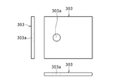
- the band auxiliary member 303 exerts an auxiliary function when being fixed to the angle member 12 by the first and second band members 301 and 302, and is formed from a strip-shaped steel plate material. As shown in FIG. 1, the band auxiliary member 303 extends in a direction away from the inner corner portion 124 of the angle member 12 so as to bisect the angle formed by both sides 121 and 122 inside the angle member 12. Are arranged.
- the connecting bolts and nuts 304 are provided on both sides 121 and 122 of the angle member 12 with one end of the band auxiliary member 303 being the first connecting portion 3013 of the first band member 301 and the second connecting portion of the second band member 302. In the state of being sandwiched by 3023, these both coupling parts 3013 and 3023 are fixed to one end of the band auxiliary member 303 and integrated.
- the tightening bolts / nuts 305 are formed on the opposite side to the inner sides of the both sides 121 and 122 of the angle member 12, that is, at the outer corner portion 123 formed by the both sides 121 and 122 and the first tightening portion 3014 of the first band member 301.
- the first band member 301 is slidably contacted along the outer surface of the one side 121 of the angle member 12 while the outer corner portion of the angle member 12 is slidably contacted. It is for moving to the 123 side.
- the tightening bolt / nut 305 moves toward the outer corner portion 123 side of the angle member 12 while slidingly contacting the second band member 302 along the outer surface of the other side 122 of the angle member 12.
- the other end 303 b of the auxiliary member 303 is for pressing against the inner corner portion 124 of the angle member 12.
- the tightening bolt / nut 305 presses the first holding portion 3011 of the first band member 301 and the second holding portion 3021 of the second band member 302 to the outer surface of both sides 121 and 122 of the angle member 12.
- the first band member 301, the second band member 302, and the band auxiliary member 303 are fixed to the angle member 12.
- the joining bolt 304 and the tightening bolt 305 may be welded to the band member in advance.
- the reinforcing device 30 When the reinforcing device 30 is attached to the angle member 12, it can be fixed by simply tightening the nut side with one spanner, and the attaching work can be simplified.
- the bending angle of the first band member 301 and the second band member 302 was about 45 degrees, but in the present embodiment, it is about 60 degrees. Since it is a very difficult work to manufacture a steel sheet by bending it at 45 degrees, it is easier to bend the steel sheet if it is set at about 60 degrees. Further, the contact between the first band member 301 and the second band member 302 and the end portion of the angle member 12 becomes gentle, and the pressure bonding property to the inside of the angle member 12 becomes higher. The distance from the coupling bolt 304 is reduced, and the amount of bending of the band members 301 and 302 and the band auxiliary member 303 can be suppressed when tightening the band, so that the band members can be more reliably fixed.
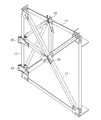
- a steel frame structure (truss structure) that constitutes a saw roof of a factory building is opposed to a horizontal member at a predetermined angle obliquely upward with respect to the horizontal member.
- the inclined members arranged, the vertical members that connect the horizontal members to each other, and the bracing members that connect the horizontal members and the inclined members that are separated by the vertical members diagonally to each other.
- the angle member 12 is made of equilateral angle steel having an L-shaped cross section. Further, both ends of each vertical member and both ends of each bracing member are connected to the horizontal member and the inclined member through gusset plates provided on the horizontal member and the inclined member.
- the steel material forming the steel frame structure for the saw roof it is possible to use a flat steel, a CT steel, a channel steel or the like in addition to the L-shaped equilateral angle steel.
- the reinforcing device 30 for reinforcing the angle member 12 shown in FIG. 11 has the configuration shown in FIGS. 1 to 4, and includes the first band member 301 and the second band member 302 that are combined so as to sandwich the angle member 12, and the angle member 12.
- the band auxiliary member 303 arranged so as to divide the inner corner portion 124 of the material 12 into two parts, the connecting bolt / nut 304 for connecting the first connecting portion 3013 and the second connecting portion 3023, the first tightening portion 3014 and the second The tightening portion 3024 and a tightening bolt / nut 305 for tightening the tightening portion 3024.
- the reinforcing ribs are provided on the lower part of the first band member 301 and the upper part of the second band member 302.
- the reinforcing ribs 3015 and 3016 provided on the first band member 301 and the reinforcing ribs 3025 and 3026 provided on the second band member 302 are alternately arranged on the upper and lower sides, so that the crimping property to the angle member 12 is improved. Well balanced.
- the existing angle member 12 can be easily and surely reinforced and reinforced. It is easy and easy to handle and manage the fixing parts at the time of implementation, and at the same time, the work time required for the reinforcement can be shortened and the cost of the reinforcement work can be reduced.
- an existing antenna tower 10 (corresponding to the structure described in the claims) is composed of four angle members 12 which are pillars made of equilateral angle steel with both sides of the L shape being equal, and these angle members 12 And a truss structure material 13 that is provided between them.
- a parabolic antenna 14 for communication is installed on the uppermost part of the antenna tower 10, and a lightning rod 15 (corresponding to incidental equipment described in the claims) extends above the antenna tower 10. .. Further, a plurality of receiving antennas 17 are installed around the platform 16 provided on the antenna tower 10 below the parabolic antenna 14. Further, a plurality of transmitting antennas 19 are installed around the platform 18 provided on the antenna tower 10 below the platform 16.
- the incidental equipment attachment device 30 is for attaching the lightning rod 15 to the angle member 12 of the antenna tower 10, and includes a fixture 20 for fixing the lightning rod 15 to the angle member 12, as shown in FIGS. ..
- the fixture 20 includes a first band member 301 and a second band member 302, which are symmetrically arranged so as to sandwich both sides of the angle member 12 from the respective outer side surfaces, a band auxiliary member 303, and a set of couplings.
- the first band member 301 and the second band member 302 correspond to the two band members in the claims.
- the first band member 301 is used for fixing the lightning rod 15 to the angle member 12, is made of a steel plate material, and is in the width direction of the one side 121 so as to be in contact with the outer surface of the one side 121 of the angle member 12. It is arranged so as to extend in a direction orthogonal to.
- the first band member 301 is in pressure contact with the outer surface of the one side 121 of the angle member 12 and has a first sandwiching portion 3011 having a length larger than the width of the one side 121.
- the first connecting portion 3012 is provided at one end of the first holding portion 3011 and extends obliquely from the one end toward the one end of the band auxiliary member 303, and is provided at the tip of the first connecting portion 3012.
- a first coupling portion 3013 coupled to one end of the auxiliary member 303 and an end portion of the first holding portion 3011 located opposite to the first coupling portion 3012 are provided to generate a tightening force on the first band member 301. It has one tightening portion 3014.
- a reinforcing rib 3015 is provided between the first connecting portion 3012 and the first connecting portion 3013 at the connecting portion between the first connecting portion 3012 and the first connecting portion 3013. It is provided in.
- a reinforcing rib 3016 is provided between the first holding portion 3011 and the first tightening portion 3014 at the joint between the first holding portion 3011 and the first tightening portion 3014. It is provided in.
- the second band member 302 is used to fix the lightning rod 15 to the angle member 12, is made of a steel plate material, and is formed in the width direction of the other side 122 so as to contact the outer surface of the other side 122 of the angle member 12. It is arranged so as to extend in a direction orthogonal to.
- the second band member 302 is in pressure contact with the outer surface of the other side 122 of the angle member 12, and has a second holding portion 3021 having a length larger than the width of the other side 122, and one end portion of the second holding portion 3021.
- a second connecting portion 3022 obliquely extending from the one end portion to one end portion of the band auxiliary member 303, and coupled to one end portion of the band auxiliary member 303 provided at the tip of the second connecting portion 3022.
- a second tightening part 3024 which is provided at the end of the second sandwiching part 3021 located opposite to the second combining part 3023 and which generates a tightening force on the second band member 302.
- a reinforcing rib 3025 is provided between the second connecting portion 3022 and the second connecting portion 3023 at the connecting portion between the second connecting portion 3022 and the second connecting portion 3023. It is provided in. Further, in order to increase the rigidity of the second band member 302, a reinforcing rib 3026 is provided between the second holding portion 3021 and the second tightening portion 3024 at a connecting portion between the second holding portion 3021 and the second tightening portion 3024. It is provided in.
- the band assisting member 303 has a strip-like shape, which has an auxiliary function when the support body 306 is fixed to the angle member 12 by the first and second band members 301 and 302 and is also used to support the support body 306. It is formed from the steel sheet material.
- the band auxiliary member 303 extends in a direction away from the inner corner portion 124 of the angle member 12 so as to bisect the angle formed by both sides 121 and 122 inside the angle member 12. Are arranged.
- the band auxiliary member 303 has a connecting portion 3031 integrally provided by extending one end of the band auxiliary member 303 opposite to the inner corner portion 124 of the angle member 12 in the longitudinal direction of the band auxiliary member 303.
- a support body 306 that supports the lightning rod 15 that is an auxiliary facility is attached to the connecting portion 3031.
- the support body 306 is for attaching the lightning rod 15 to the fixture 30, and as shown in FIGS. 13 and 14, a cylindrical support 306a of a predetermined length and a reinforcing member fixed to the outer periphery of the lower end of the support 306a by welding. It has a mounting portion 306c with a rib 306b, and by mounting this mounting portion 306c to the connecting portion 3031 with a bolt / nut 307 consisting of a set of high-strength bolts / nuts, the lightning rod 15 is integrated with the angle member 12. It is configured to be fixed.
- the connecting bolts and nuts 304 are provided on both sides 121 and 122 of the angle member 12 with one end of the band auxiliary member 303 being the first connecting portion 3013 of the first band member 301 and the second connecting portion of the second band member 302.
- these both coupling parts 3013 and 3023 are fixed to one end of the band assisting member 303 to be integrated, and are composed of high-strength bolts and nuts, in addition to the coupling nut 304a,
- a lock nut 304b is provided to prevent the coupling nut 304a from loosening.
- the tightening bolts / nuts 305 are formed on the opposite side to the inner sides of the both sides 121 and 122 of the angle member 12, that is, at the outer corner portion 123 formed by the both sides 121 and 122 and the first tightening portion 3014 of the first band member 301.
- the first band member 301 is slidably contacted along the outer surface of the one side 121 of the angle member 12 while the outer corner portion of the angle member 12 is slidably contacted. It is for moving to the 123 side.
- the tightening bolt / nut 305 moves toward the outer corner portion 123 side of the angle member 12 while slidingly contacting the second band member 302 along the outer surface of the other side 122 of the angle member 12.
- the other end 303 b of the auxiliary member 303 is for pressing against the inner corner portion 124 of the angle member 12.
- the tightening bolt / nut 305 presses the first holding portion 3011 of the first band member 301 and the second holding portion 3021 of the second band member 302 to the outer surface of both sides 121 and 122 of the angle member 12. This is for fixing the first band member 301, the second band member 302, and the band auxiliary member 303 to the angle member 12.
- the tightening bolt / nut 305 is a high-strength bolt / nut, and in addition to the tightening nut 305a, a lock nut 305b for preventing the tightening nut 305a from loosening is provided.
- the first coupling portion 3013 of the first band member 301 and the second coupling portion 3023 of the second band member 302 are superposed on both sides of the band assistance member 303 in plane symmetry, and the band assistance member is The bolt hole 303a of the first coupling portion 3013 and the bolt hole 3023a of the second coupling portion 3023 are aligned with the bolt hole 303a of the 303.
- the bolts of the coupling bolts and nuts 304 are inserted into the bolt holes of these three members, and the coupling nuts 304a are screwed into the insertion tip portions of the first band member 301 and the second band member 302. Temporarily coupled to the auxiliary member 303.
- the bolts of the joining bolts and nuts 304 can be opened in a direction away from the band auxiliary member 303 with the bolts as fulcrums.
- the distance between the first tightening portion 3014 including the first sandwiching portion 3011 of the first band member 301 and the second tightening portion 3024 including the second sandwiching portion 3021 of the second band member 302 is set to be equal to both sides of the angle member 12. It is preferable that the first band member 301 and the second band member 302 are incorporated in the angle member 12 by making the gap larger than the interval between 121 and 122.
- the first band member 301 and the second band member 302 in the opened state are rotated in a direction in which the angle member 12 is sandwiched from both side surfaces by using the bolts of the connecting bolts and nuts 304 as fulcrums, and then the first band member
- the first holding portion 3011 of the member 301 is brought into contact with the outer surface of the one side 121 of the angle member 12, and the second holding portion 3021 of the second band member 302 is brought into contact with the outer surface of the other side 122 of the angle member 12.
- the first band member 301 and the second band member 302 are fixed to the band auxiliary member 303 by tightening the coupling nut 304a, and the first sandwiching portion 3011 is attached to the outer surface of the side 121 on one side of the angle member 12.
- the second holding portion 3021 is pressed against the outer surface of the other side 122 of the angle member 12.
- the lock band 304b is screwed onto the bolt of the coupling bolt / nut 304 and tightened to securely fix the first band member 301 and the second band member 302 to the band auxiliary member 303.
- the bolts of the tightening bolts and nuts 305 are inserted through the bolt holes 3014a formed in the first tightening portion 3014 of the first band member 301 and the bolt holes 3024a formed in the second tightening portion 3024 of the second band member 302. ,
- the first tightening portion 3014 and the second tightening portion 3024 are tightened in a direction in which they approach each other by screwing a tightening nut 305a into the insertion end portion of the first band member 301 to one side of the angle member 12.
- the angle member 12 is slid toward the outside corner portion 123 side of the angle member 12 while being pressed against the outside surface of the angle member 121, and at the same time, the second band member 302 is pressed along the outside surface of the other side 122 of the angle member 12. To the outside corner portion 123 side.
- the other end portion 303b of the band assisting member 303 is strongly pressed against the inner corner portion 124 of the angle member 12, and the first holding portion 3011 of the first band member 301 and the second holding portion 3021 of the second band member 302 are pushed.
- the outer surface of one side 121 and the outer surface of the other side 122 of the angle member 12 are brought into pressure contact with each other.
- the first and second band members 301, 302 and the band auxiliary member 303 are fixed to the angle member 12 and integrated.
- the lock nut 305b is screwed onto the bolt of the tightening bolt / nut 305 and tightened to securely fix the fixture 20 to the angle member 12.
- a part of the first sandwiching portion 3011 of the first band member 301 near the first tightening portion 3014 partially comes into pressure contact with the outer surface of the one side 121 of the angle member 12, and A part of the second holding part 3021 of the 2 band member 302 near the second tightening part 3024 partially press-contacts with the outer surface of the other side 122 of the angle member 12, and does not contact with other parts except these parts.
- the outer side surfaces of both sides 121 and 122 of the angle member 12 and the first holding portion 3011 of the first band member 301 and the second holding portion 3021 of the second band member 302, which are opposed to the outer side surfaces contact the entire surface. It is desirable that the structure has a partial contact structure and that the tightening force is concentrated on both side corners of the angle member 12.
- the attachment portion 306c provided on the column 306a is connected to the band auxiliary member 303 by a set of bolts and nuts 307. It is performed by fixing to 3031.
- the number of the fixtures 20 for fixing the support 306a of the support body 306 to the angle member 12 is not limited to one, and a plurality of fixtures 20 may be used depending on the function, scale, installation location, etc. of the lightning rod 15.
- the procedure for attaching the incidental equipment attaching device 30 to the angle member 12 is not limited to the above-described method, and may be changed according to the environment of the steel tower to which the incidental equipment attaching device 30 is attached or the attaching position to the iron tower. Is done.
- the first band member 301 and the second band member 302 are integrally coupled to the band auxiliary member 303 by the coupling bolts and nuts 304, and in this state, By tightening the first tightening portion 3014 of the first band member 301 and the second tightening portion 3024 of the second band member 302 with the tightening bolts and nuts 305 in a direction in which they approach each other, the first band member 301 is made of an angle member.
- the first band member 301 is slid to the outer corner portion 123 side of the angle member 12 while being pressed against the outer surface of one side 121 of the angle member 12, and the second band member 302 is moved to the other side 122 of the angle member 12.
- the angle member 12 While being pressed against the outer surface, the angle member 12 is slid toward the outer corner portion 123 side, and further, the band auxiliary member 303 The end portion 303b is strongly pressed against the inner corner portion 124 of the angle member 12, and the first holding portion 3011 of the first band member 301 and the second holding portion 3021 of the second band member 302 are connected to one side 121 of the angle member 12.
- the band auxiliary member 303 and the first and second band members 301 and 302 are fixed to and integrated with the angle member 12 by press-contacting the outer surface and the outer surface of the other side 122, respectively.
- the fastener 20 is fixed to the angle member 12 only by tightening the tightening bolts and nuts 305 in the direction in which the first tightening portion 3014 of the first band member 301 and the second tightening portion 3024 of the second band member 302 approach each other. Since it can be fixed, efficiency and cost reduction of the work of attaching the lightning rod 15 to the steel tower can be realized.
- first band member 301 and the second band member 302 are reinforced by the reinforcing ribs 3015, 3016, 3025, 3026, the rigidity of the first and second band members 301, 302 is improved and the fixture 20
- the angle member 12 and the angle member 12 can be integrated more strongly.
- the incidental equipment attachment device 30 is not limited to the attachment of the antenna and the lightning rod to the steel tower shown in the above embodiment, and the angle material made of the angle steel or the pair of angle steel materials forming the parallel type angle steel assembly. It is needless to say that the present invention can be applied to the attachment of other incidental equipment including an antenna and a lightning rod to a structure using, and various changes can be made without departing from the requirements described in the claims.
Landscapes
- Engineering & Computer Science (AREA)
- Architecture (AREA)
- Structural Engineering (AREA)
- Civil Engineering (AREA)
- Chemical & Material Sciences (AREA)
- Materials Engineering (AREA)
- Wood Science & Technology (AREA)
- Life Sciences & Earth Sciences (AREA)
- Chemical Kinetics & Catalysis (AREA)
- Electrochemistry (AREA)
- Mechanical Engineering (AREA)
- Working Measures On Existing Buildindgs (AREA)
- Clamps And Clips (AREA)
- Mutual Connection Of Rods And Tubes (AREA)
Abstract
Description
以下、本発明に係る既設構造物の補強装置30の第1の実施形態について、図1~4を参照して説明する。
以下、本発明に係る補強装置30を用いてアングル材12の補強をする第2の実施形態について、図9~11を参照して説明する。
以下、本発明に係る付帯設備取付装置を用いて避雷針15を取り付ける第38の実施形態について、図12~16を参照して説明する。
30…補強装置または付帯設備取付装置、301…第1バンド部材、3011…第1挟持部、3012…第1連結部、3013…第1結合部、3014…第1締め付け部、3015…補強用リブ、3016…補強用リブ、302…第2バンド部材、3021…第2挟持部、3022…第2連結部、3023…第2結合部、3024…第2締め付け部、3025…補強用リブ、3026…補強用リブ、3027…屈曲部、3028…屈曲部、303…バンド補助部材、303a…バンド補助部材のボルト孔、303b…バンド補助部材の他端部、3031…連結部、304…結合用ボルト・ナット、304a…結合用ナット、304b…ロックナット、305…締め付け用ボルト・ナット、305a…締め付け用ナット、305b…ロックナット、306…支持体、306a…支柱、306b…補強用リブ、306c…取付部
Claims (6)
- 断面がL形を呈する両辺を有するアングル材を用いて構成されている既設構造物の補強装置であって、
前記補強装置は、
前記アングル材の両辺をそれぞれの外側面側から挟持するように配置される2つのバンド部材と、
前記アングル材の内側に該アングル材の両辺が形成する角度を二分するように前記アングル材の内側角部から離間する方向に延在して配置されるバンド補助部材と、
前記アングル材から突出する前記バンド補助部材の延在端部と、前記各バンド部材の一端部とを結合する結合用ボルト・ナットと、
前記アングル材の両辺が形成する外側角部側で前記各バンド部材の他端部を互いに接近する方向に締め付けることにより前記各バンド部材を前記アングル材の辺の外側面に沿い摺接させながら前記外側角部側へ移動し、前記バンド補助部材の端縁を前記アングル材の内側角部に押圧することにより前記バンド補助部材を前記アングル材に一体に固定する締め付け用ボルト・ナットと、
を有する既設構造物の補強装置において、
前記結合用ボルト・ナットおよび前記締め付け用ボルト・ナットは、前記バンド部材の前記一端部および前記他端部に、それぞれ複数組配置する構成とはせずに、それぞれ1組のみ配置するようにし、
前記バンド部材の外面には補強用リブが設けられており、
前記補強用リブは、前記2つのバンド部材の上部または下部のいずれか一方に設けられており、
前記補強用リブは、前記2つのバンド部材を組み合わせて前記アングル材に取り付けた時に前記2つのバンド部材の補強用リブが互いに上下異なる側に位置するようにしたことを特徴とする既設構造物の補強装置。 - 請求項1記載の既設構造物の補強装置において、
前記各バンド部材は、前記一方の辺の幅より大きい長さを有しかつ当該一方の辺の外側面に摺接される挟持部と、前記バンド補助部材の延在端部に前記結合用ボルト・ナットにより結合される結合部と、前記挟持部と前記結合部とを連結する連結部と、前記連結部と反対に位置する前記挟持部の端部に設けられた締め付け部を有し、
前記締め付け用ボルト・ナットにより互いに接近する方向に締め付けられる前記各バンド部材の他端部は、前記締め付け部であることを特徴とする既設構造物の補強装置。 - 請求項1または2記載の既設構造物の補強装置において、
組み合わせる2つの前記バンド部材において、
いずれか一方の前記バンド部材の長手方向の端部が他方のバンド部材の長手方向の端部を覆うように屈曲している
ことを特徴とする既設構造物の補強装置。 - 構造物を構成する断面がL形を呈する両辺を有するアングル材に付帯設備を取り付けるための付帯設備取付装置であって、
前記付帯設備を前記アングル材に固定する固定具を備え、
前記固定具は、
前記アングル材の両辺をそれぞれの外側面側から挟持するように配置される2つのバンド部材と、
前記アングル材の内側に該アングル材の両辺が形成する角度を二分するように前記アングル材の内側角部から離間する方向に延在して配置されるバンド補助部材と、
前記アングル材から突出する前記バンド補助部材の延在端部と、前記各バンド部材の一端部とを結合する結合用ボルト・ナットと、
前記アングル材の両辺が形成する外側角部側で前記各バンド部材の他端部を互いに接近する方向に締め付けることにより前記各バンド部材を前記アングル材の辺の外側面に沿い摺接させながら前記外側角部側へ移動し、前記バンド補助部材の端縁を前記アングル材の内側角部に押圧することより前記バンド補助部材を前記アングル材に一体に固定する締め付け用ボルト・ナットと、
前記バンド補助部材の延在端部に設けられ前記付帯設備が取り付けられる支持体とを有する付帯設備取付装置において、
前記結合用ボルト・ナットおよび前記締め付け用ボルト・ナットは、前記バンド部材の前記一端部および前記他端部に、それぞれ複数組配置する構成とはせずに、それぞれ1組のみ配置するようにし、
前記バンド部材の外面には補強用リブが設けられており、
前記補強用リブは、前記2つのバンド部材の上部または下部のいずれか一方に設けられており、
前記補強用リブは、前記2つのバンド部材を組み合わせて前記アングル材に取り付けた時に前記2つのバンド部材の補強用リブが互いに上下異なる側に位置するようにしたことを特徴とする付帯設備取付装置。 - 請求項4記載の付帯設備取付装置において、
前記各バンド部材は、前記一方の辺の幅より大きい長さを有しかつ当該一方の辺の外側面に摺接される挟持部と、前記バンド補助部材の延在端部に前記結合用ボルト・ナットにより結合される結合部と、前記挟持部と前記結合部とを連結する連結部と、前記連結部と反対に位置する前記挟持部の端部に設けられた締め付け部を有し、
前記締め付け用ボルト・ナットにより互いに接近する方向に締め付けられる前記各バンド部材の他端部は、前記締め付け部であることを特徴とする付帯設備取付装置。 - 請求項4または5記載の付帯設備取付装置において、
組み合わせる2つの前記バンド部材において、
いずれか一方の前記バンド部材の長手方向の端部が他方のバンド部材の長手方向の端部を覆うように屈曲していることを特徴とする付帯設備取付装置。
Priority Applications (9)
| Application Number | Priority Date | Filing Date | Title |
|---|---|---|---|
| CN201980033181.9A CN112189076A (zh) | 2018-11-01 | 2019-10-08 | 现有结构物的加强装置及附带设备安装装置 |
| NZ775492A NZ775492B2 (en) | 2018-11-01 | 2019-10-08 | Reinforcement device for existing structure and incidental facility attaching device |
| CA3083455A CA3083455C (en) | 2018-11-01 | 2019-10-08 | Reinforcing device of existing structure and incidental equipment attaching device |
| EP19878658.4A EP3875710A4 (en) | 2018-11-01 | 2019-10-08 | REINFORCEMENT DEVICE FOR EXISTING STRUCTURE AND DEVICE FOR ATTACHING AN RANDOM INSTALLATION |
| US16/961,335 US11286680B2 (en) | 2018-11-01 | 2019-10-08 | Reinforcement device for existing structure and incidental facility attaching device |
| MYPI2020003253A MY201344A (en) | 2018-11-01 | 2019-10-08 | Reinforcing device of existing structure and incidental equipment attaching device |
| RU2020129201A RU2754690C1 (ru) | 2018-11-01 | 2019-10-08 | Устройство для усиления существующей конструкции и устройство для крепления дополнительного оборудования |
| AU2019372495A AU2019372495B2 (en) | 2018-11-01 | 2019-10-08 | Reinforcement device for existing structure and incidental facility attaching device |
| PH12020550710A PH12020550710A1 (en) | 2018-11-01 | 2020-05-26 | Reinforcing device of existing structure and incidental equipment attaching device |
Applications Claiming Priority (2)
| Application Number | Priority Date | Filing Date | Title |
|---|---|---|---|
| JP2018206306A JP6591026B1 (ja) | 2018-11-01 | 2018-11-01 | 既設構造物の補強装置および付帯設備取付装置 |
| JP2018-206306 | 2018-11-01 |
Publications (1)
| Publication Number | Publication Date |
|---|---|
| WO2020090370A1 true WO2020090370A1 (ja) | 2020-05-07 |
Family
ID=68234856
Family Applications (1)
| Application Number | Title | Priority Date | Filing Date |
|---|---|---|---|
| PCT/JP2019/039570 Ceased WO2020090370A1 (ja) | 2018-11-01 | 2019-10-08 | 既設構造物の補強装置および付帯設備取付装置 |
Country Status (11)
| Country | Link |
|---|---|
| US (1) | US11286680B2 (ja) |
| EP (1) | EP3875710A4 (ja) |
| JP (1) | JP6591026B1 (ja) |
| CN (1) | CN112189076A (ja) |
| AU (1) | AU2019372495B2 (ja) |
| CA (1) | CA3083455C (ja) |
| MY (1) | MY201344A (ja) |
| PH (1) | PH12020550710A1 (ja) |
| RU (1) | RU2754690C1 (ja) |
| SA (1) | SA521421729B1 (ja) |
| WO (1) | WO2020090370A1 (ja) |
Families Citing this family (3)
| Publication number | Priority date | Publication date | Assignee | Title |
|---|---|---|---|---|
| CN113789973B (zh) * | 2021-09-15 | 2022-05-24 | 山东大学 | 一种螺栓承压环抱式输电铁塔角钢加固与矫正装置 |
| CN114109119B (zh) * | 2021-12-13 | 2023-07-11 | 国网陕西省电力公司榆林供电公司 | 一种输电塔主材碳纤维装配式加固结构 |
| CN114517592B (zh) * | 2021-12-31 | 2023-07-25 | 中国能源建设集团广东省电力设计研究院有限公司 | 一种铁塔角钢加固结构以及加固方法 |
Citations (8)
| Publication number | Priority date | Publication date | Assignee | Title |
|---|---|---|---|---|
| JPS6119786B2 (ja) * | 1981-08-26 | 1986-05-19 | Tohoku Denryoku Kk | |
| JPS631212B2 (ja) | 1981-04-01 | 1988-01-11 | Nissan Motor | |
| JPS6464B2 (ja) * | 1981-05-13 | 1989-01-05 | Terumo Corp | |
| JP2008291620A (ja) * | 2007-05-24 | 2008-12-04 | Keigo Ishii | 補強金物 |
| JP2008308937A (ja) * | 2007-06-18 | 2008-12-25 | Daiwa House Ind Co Ltd | 座屈拘束ブレース |
| JP2014139384A (ja) * | 2013-01-21 | 2014-07-31 | I&C Consulting Co Ltd | 山形鋼の補強装置及び山形鋼の補強施行方法 |
| JP2018080482A (ja) | 2016-11-15 | 2018-05-24 | 株式会社アイ・ティ・シ・コンサルティング | 付帯設備取付装置 |
| JP6368569B2 (ja) * | 2014-07-15 | 2018-08-01 | 株式会社アイ・ティ・シ・コンサルティング | 既設鉄骨構造物の補強装置 |
Family Cites Families (18)
| Publication number | Priority date | Publication date | Assignee | Title |
|---|---|---|---|---|
| US1403051A (en) * | 1920-04-10 | 1922-01-10 | Henry E Moore | Steel tower |
| US2073889A (en) * | 1934-06-09 | 1937-03-16 | William A Trout | Framed structure |
| US2145232A (en) * | 1937-06-24 | 1939-01-31 | Missouri Rolling Mill Corp | Steel tower member |
| US2664636A (en) * | 1952-05-26 | 1954-01-05 | Kenneth E Schneider | Line holder |
| US3499258A (en) * | 1966-11-08 | 1970-03-10 | Richier Sa | Assembled steel structure sections |
| SU1096368A1 (ru) * | 1982-11-15 | 1984-06-07 | Государственный Проектный Институт "Днепрпроектстальконструкция" | Усиление узла металлической фермы |
| SU1206413A1 (ru) * | 1984-02-23 | 1986-01-23 | Государственный Проектный И Научно-Исследовательский Институт "Укрниипроектстальконструкция" | Устройство дл усилени сжатого стержн |
| JPS6119786A (ja) | 1984-07-09 | 1986-01-28 | Honda Motor Co Ltd | 鉄及び鉄合金、銅及び銅合金、亜鉛、亜鉛メッキ、アルミニウムの気化性防錆剤 |
| US7836656B2 (en) * | 2007-06-01 | 2010-11-23 | Crosbie Patrick J | Tower module, system and method |
| US20090025308A1 (en) * | 2007-07-26 | 2009-01-29 | Deans Brian W | Seismic support and reinforcement systems |
| JP2010024747A (ja) * | 2008-07-22 | 2010-02-04 | Tokyo Electric Power Co Inc:The | 山形鋼部材の座屈補強方法及び当該方法において使用する補強具 |
| KR101019425B1 (ko) * | 2008-09-26 | 2011-03-07 | 한국전력공사 | 압축좌굴내력 보강기구 및 이의 체결 방법 |
| US8307609B2 (en) * | 2010-04-01 | 2012-11-13 | Korea Electric Power Corporation | Reinforcement device for lateral buckling stress and method of engaging reinforcement device |
| CN202359830U (zh) * | 2011-07-21 | 2012-08-01 | 天津求实电力规划设计有限公司 | 新型输电铁塔的加固装置 |
| JP6210453B2 (ja) * | 2013-09-30 | 2017-10-11 | 三和テッキ株式会社 | アングル鉄塔用の支線取付金具 |
| JP6301212B2 (ja) | 2014-07-15 | 2018-03-28 | 株式会社アイ・ティ・シ・コンサルティング | 既設鉄骨構造物の補強装置 |
| CN104389438B (zh) * | 2014-12-10 | 2017-03-01 | 华北水利水电大学 | 一种混凝土柱的抗震加固机构和方法 |
| JP6119786B2 (ja) * | 2015-03-25 | 2017-04-26 | コニカミノルタ株式会社 | 静電潜像現像用トナー |
-
2018
- 2018-11-01 JP JP2018206306A patent/JP6591026B1/ja active Active
-
2019
- 2019-10-08 WO PCT/JP2019/039570 patent/WO2020090370A1/ja not_active Ceased
- 2019-10-08 RU RU2020129201A patent/RU2754690C1/ru active
- 2019-10-08 CA CA3083455A patent/CA3083455C/en active Active
- 2019-10-08 AU AU2019372495A patent/AU2019372495B2/en active Active
- 2019-10-08 US US16/961,335 patent/US11286680B2/en active Active
- 2019-10-08 MY MYPI2020003253A patent/MY201344A/en unknown
- 2019-10-08 CN CN201980033181.9A patent/CN112189076A/zh active Pending
- 2019-10-08 EP EP19878658.4A patent/EP3875710A4/en active Pending
-
2020
- 2020-05-26 PH PH12020550710A patent/PH12020550710A1/en unknown
-
2021
- 2021-04-12 SA SA521421729A patent/SA521421729B1/ar unknown
Patent Citations (8)
| Publication number | Priority date | Publication date | Assignee | Title |
|---|---|---|---|---|
| JPS631212B2 (ja) | 1981-04-01 | 1988-01-11 | Nissan Motor | |
| JPS6464B2 (ja) * | 1981-05-13 | 1989-01-05 | Terumo Corp | |
| JPS6119786B2 (ja) * | 1981-08-26 | 1986-05-19 | Tohoku Denryoku Kk | |
| JP2008291620A (ja) * | 2007-05-24 | 2008-12-04 | Keigo Ishii | 補強金物 |
| JP2008308937A (ja) * | 2007-06-18 | 2008-12-25 | Daiwa House Ind Co Ltd | 座屈拘束ブレース |
| JP2014139384A (ja) * | 2013-01-21 | 2014-07-31 | I&C Consulting Co Ltd | 山形鋼の補強装置及び山形鋼の補強施行方法 |
| JP6368569B2 (ja) * | 2014-07-15 | 2018-08-01 | 株式会社アイ・ティ・シ・コンサルティング | 既設鉄骨構造物の補強装置 |
| JP2018080482A (ja) | 2016-11-15 | 2018-05-24 | 株式会社アイ・ティ・シ・コンサルティング | 付帯設備取付装置 |
Non-Patent Citations (1)
| Title |
|---|
| See also references of EP3875710A4 |
Also Published As
| Publication number | Publication date |
|---|---|
| AU2019372495B2 (en) | 2020-10-01 |
| EP3875710A1 (en) | 2021-09-08 |
| NZ775492A (en) | 2021-10-29 |
| JP6591026B1 (ja) | 2019-10-16 |
| CN112189076A (zh) | 2021-01-05 |
| RU2754690C1 (ru) | 2021-09-06 |
| SA521421729B1 (ar) | 2022-11-13 |
| CA3083455C (en) | 2021-01-12 |
| JP2020070652A (ja) | 2020-05-07 |
| CA3083455A1 (en) | 2020-05-07 |
| MY201344A (en) | 2024-02-17 |
| AU2019372495A1 (en) | 2020-06-04 |
| EP3875710A4 (en) | 2022-07-06 |
| PH12020550710A1 (en) | 2021-04-26 |
| US20210310264A1 (en) | 2021-10-07 |
| US11286680B2 (en) | 2022-03-29 |
Similar Documents
| Publication | Publication Date | Title |
|---|---|---|
| JP6400064B2 (ja) | 付帯設備取付装置 | |
| US8732917B2 (en) | Standing seam roof clamp | |
| WO2020090370A1 (ja) | 既設構造物の補強装置および付帯設備取付装置 | |
| JP2013151832A (ja) | 鉄骨部材の補剛構造及び方法 | |
| JP4683579B1 (ja) | 木造建築物の補強構造 | |
| JP5060278B2 (ja) | 新設下地材及びその取付構造 | |
| JP2009215824A (ja) | 鋼構造の補強構造 | |
| JP6301212B2 (ja) | 既設鉄骨構造物の補強装置 | |
| JP2017057704A (ja) | ブレース連結金具 | |
| JP5912481B2 (ja) | 建築用取付具 | |
| JP4771861B2 (ja) | 鋼構造の補強構造 | |
| JP3234289U (ja) | クランプ装置 | |
| JP6368569B2 (ja) | 既設鉄骨構造物の補強装置 | |
| JP3153547U (ja) | 鉄骨柱及び鉄骨梁の接合構造 | |
| NZ775492B2 (en) | Reinforcement device for existing structure and incidental facility attaching device | |
| JP2011174333A (ja) | 屋根上取付具およびその取付構造 | |
| JPH0374312B2 (ja) | ||
| KR100468512B1 (ko) | 강관비계 결속용 클램프 | |
| JP3161023U (ja) | 鉄骨柱及び鉄骨梁の接合構造 | |
| CN212163203U (zh) | 矩形管束锁付支架 | |
| JPH08135016A (ja) | 鉄骨部材の接合金物 | |
| JP2000179076A (ja) | 壁体取付構造 | |
| JPS6353338B2 (ja) | ||
| JP2018003248A (ja) | 支柱台座 | |
| JPH0635009Y2 (ja) | 取付金具 |
Legal Events
| Date | Code | Title | Description |
|---|---|---|---|
| ENP | Entry into the national phase |
Ref document number: 3083455 Country of ref document: CA |
|
| ENP | Entry into the national phase |
Ref document number: 2019372495 Country of ref document: AU Date of ref document: 20191008 Kind code of ref document: A |
|
| 121 | Ep: the epo has been informed by wipo that ep was designated in this application |
Ref document number: 19878658 Country of ref document: EP Kind code of ref document: A1 |
|
| NENP | Non-entry into the national phase |
Ref country code: DE |
|
| ENP | Entry into the national phase |
Ref document number: 2019878658 Country of ref document: EP Effective date: 20210601 |