WO2020101003A1 - Pneu à roulage à plat - Google Patents
Pneu à roulage à plat Download PDFInfo
- Publication number
- WO2020101003A1 WO2020101003A1 PCT/JP2019/044781 JP2019044781W WO2020101003A1 WO 2020101003 A1 WO2020101003 A1 WO 2020101003A1 JP 2019044781 W JP2019044781 W JP 2019044781W WO 2020101003 A1 WO2020101003 A1 WO 2020101003A1
- Authority
- WO
- WIPO (PCT)
- Prior art keywords
- bead filler
- tire
- bead
- height
- run
- Prior art date
- Legal status (The legal status is an assumption and is not a legal conclusion. Google has not performed a legal analysis and makes no representation as to the accuracy of the status listed.)
- Ceased
Links
Images



Classifications
-
- B—PERFORMING OPERATIONS; TRANSPORTING
- B60—VEHICLES IN GENERAL
- B60C—VEHICLE TYRES; TYRE INFLATION; TYRE CHANGING; CONNECTING VALVES TO INFLATABLE ELASTIC BODIES IN GENERAL; DEVICES OR ARRANGEMENTS RELATED TO TYRES
- B60C15/00—Tyre beads, e.g. ply turn-up or overlap
- B60C15/0009—Tyre beads, e.g. ply turn-up or overlap features of the carcass terminal portion
- B60C15/0036—Tyre beads, e.g. ply turn-up or overlap features of the carcass terminal portion with high ply turn-up, i.e. folded around the bead core and terminating radially above the point of maximum section width
-
- B—PERFORMING OPERATIONS; TRANSPORTING
- B60—VEHICLES IN GENERAL
- B60C—VEHICLE TYRES; TYRE INFLATION; TYRE CHANGING; CONNECTING VALVES TO INFLATABLE ELASTIC BODIES IN GENERAL; DEVICES OR ARRANGEMENTS RELATED TO TYRES
- B60C15/00—Tyre beads, e.g. ply turn-up or overlap
- B60C15/0009—Tyre beads, e.g. ply turn-up or overlap features of the carcass terminal portion
- B60C15/0054—Tyre beads, e.g. ply turn-up or overlap features of the carcass terminal portion with ply turn-up portion parallel and adjacent to carcass main portion
-
- B—PERFORMING OPERATIONS; TRANSPORTING
- B60—VEHICLES IN GENERAL
- B60C—VEHICLE TYRES; TYRE INFLATION; TYRE CHANGING; CONNECTING VALVES TO INFLATABLE ELASTIC BODIES IN GENERAL; DEVICES OR ARRANGEMENTS RELATED TO TYRES
- B60C15/00—Tyre beads, e.g. ply turn-up or overlap
- B60C15/06—Flipper strips, fillers, or chafing strips and reinforcing layers for the construction of the bead
- B60C15/0603—Flipper strips, fillers, or chafing strips and reinforcing layers for the construction of the bead characterised by features of the bead filler or apex
-
- B—PERFORMING OPERATIONS; TRANSPORTING
- B60—VEHICLES IN GENERAL
- B60C—VEHICLE TYRES; TYRE INFLATION; TYRE CHANGING; CONNECTING VALVES TO INFLATABLE ELASTIC BODIES IN GENERAL; DEVICES OR ARRANGEMENTS RELATED TO TYRES
- B60C15/00—Tyre beads, e.g. ply turn-up or overlap
- B60C15/06—Flipper strips, fillers, or chafing strips and reinforcing layers for the construction of the bead
- B60C15/0603—Flipper strips, fillers, or chafing strips and reinforcing layers for the construction of the bead characterised by features of the bead filler or apex
- B60C15/0607—Flipper strips, fillers, or chafing strips and reinforcing layers for the construction of the bead characterised by features of the bead filler or apex comprising several parts, e.g. made of different rubbers
-
- B—PERFORMING OPERATIONS; TRANSPORTING
- B60—VEHICLES IN GENERAL
- B60C—VEHICLE TYRES; TYRE INFLATION; TYRE CHANGING; CONNECTING VALVES TO INFLATABLE ELASTIC BODIES IN GENERAL; DEVICES OR ARRANGEMENTS RELATED TO TYRES
- B60C17/00—Tyres characterised by means enabling restricted operation in damaged or deflated condition; Accessories therefor
- B60C17/0009—Tyres characterised by means enabling restricted operation in damaged or deflated condition; Accessories therefor comprising sidewall rubber inserts, e.g. crescent shaped inserts
-
- B—PERFORMING OPERATIONS; TRANSPORTING
- B60—VEHICLES IN GENERAL
- B60C—VEHICLE TYRES; TYRE INFLATION; TYRE CHANGING; CONNECTING VALVES TO INFLATABLE ELASTIC BODIES IN GENERAL; DEVICES OR ARRANGEMENTS RELATED TO TYRES
- B60C15/00—Tyre beads, e.g. ply turn-up or overlap
- B60C15/06—Flipper strips, fillers, or chafing strips and reinforcing layers for the construction of the bead
- B60C15/0603—Flipper strips, fillers, or chafing strips and reinforcing layers for the construction of the bead characterised by features of the bead filler or apex
- B60C2015/061—Dimensions of the bead filler in terms of numerical values or ratio in proportion to section height
-
- B—PERFORMING OPERATIONS; TRANSPORTING
- B60—VEHICLES IN GENERAL
- B60C—VEHICLE TYRES; TYRE INFLATION; TYRE CHANGING; CONNECTING VALVES TO INFLATABLE ELASTIC BODIES IN GENERAL; DEVICES OR ARRANGEMENTS RELATED TO TYRES
- B60C15/00—Tyre beads, e.g. ply turn-up or overlap
- B60C15/06—Flipper strips, fillers, or chafing strips and reinforcing layers for the construction of the bead
- B60C2015/0617—Flipper strips, fillers, or chafing strips and reinforcing layers for the construction of the bead comprising a cushion rubber other than the chafer or clinch rubber
- B60C2015/0621—Flipper strips, fillers, or chafing strips and reinforcing layers for the construction of the bead comprising a cushion rubber other than the chafer or clinch rubber adjacent to the carcass turnup portion
-
- B—PERFORMING OPERATIONS; TRANSPORTING
- B60—VEHICLES IN GENERAL
- B60C—VEHICLE TYRES; TYRE INFLATION; TYRE CHANGING; CONNECTING VALVES TO INFLATABLE ELASTIC BODIES IN GENERAL; DEVICES OR ARRANGEMENTS RELATED TO TYRES
- B60C17/00—Tyres characterised by means enabling restricted operation in damaged or deflated condition; Accessories therefor
- B60C17/0009—Tyres characterised by means enabling restricted operation in damaged or deflated condition; Accessories therefor comprising sidewall rubber inserts, e.g. crescent shaped inserts
- B60C2017/0054—Physical properties or dimensions of the inserts
-
- B—PERFORMING OPERATIONS; TRANSPORTING
- B60—VEHICLES IN GENERAL
- B60C—VEHICLE TYRES; TYRE INFLATION; TYRE CHANGING; CONNECTING VALVES TO INFLATABLE ELASTIC BODIES IN GENERAL; DEVICES OR ARRANGEMENTS RELATED TO TYRES
- B60C17/00—Tyres characterised by means enabling restricted operation in damaged or deflated condition; Accessories therefor
- B60C17/0009—Tyres characterised by means enabling restricted operation in damaged or deflated condition; Accessories therefor comprising sidewall rubber inserts, e.g. crescent shaped inserts
- B60C2017/0054—Physical properties or dimensions of the inserts
- B60C2017/0063—Modulus; Hardness; Loss modulus or "tangens delta"
Definitions
- the present invention relates to a run flat tire.
- Pneumatic tires are attached to the rim and are mounted on the vehicle with the inside filled with air.
- the internal air pressure causes the load when the vehicle is running, but when the air inside the pneumatic tire leaks due to puncture or the like. , It becomes difficult to receive the load. In other words, since the load supported by the air pressure is supported by the sidewall portion, the sidewall portion is greatly deformed, which makes traveling difficult.
- run-flat running As a pneumatic tire capable of running in a state where air leaks due to puncture, so-called run-flat running, a side reinforcing rubber layer is provided inside the sidewall part to improve bending rigidity of the sidewall part.
- Run-flat tires are known. That is, the run-flat tire can travel by suppressing the deformation of the sidewall portion even when the air filled therein leaks and a large load acts on the sidewall portion.
- run-flat tires may have a poorer riding comfort due to the side reinforcing rubber layer.
- a large load is applied to the sidewalls, ensuring durability. Will also be important. Therefore, various techniques are used in the conventional run-flat tire having the side reinforcing rubber layer in order to ensure these performances.
- a side reinforcing rubber layer is provided in the sidewall portion, and a rubber member according to the purpose is arranged outside the turnup portion of the carcass in the tire width direction. This improves ride comfort and durability during runflat driving.
- Japanese Patent No. 5228794 Japanese Patent No. 6319415 JP, 2005-205594, A JP, 2017-56815, A Japanese Patent No. 6249518 Japanese Patent No. 5835171
- the durability in the run-flat running also tends to be improved, but when the rigidity in the tire radial direction becomes higher, the riding comfort in normal running deteriorates. Easier to do.
- the run-flat durability which is the durability during run-flat traveling
- the ride-comfort performance which is the riding comfort during normal traveling
- the present invention has been made in view of the above, and an object of the present invention is to provide a run flat tire that can achieve both run flat durability and riding comfort performance.
- a run flat tire according to the present invention has a sidewall portion arranged on both sides in the tire width direction and a tire radial direction inner side of each sidewall portion.
- a carcass to be folded back a side reinforcing rubber layer arranged on the tire inner surface side of the carcass in the sidewall portion, and a tire width direction inner side of a turnup portion that is a portion folded back to the tire width direction outer side of the bead core in the carcass.
- first bead filler arranged on the tire radial direction outer side of the bead core, and a second bead filler arranged on the tire width direction outer side of the turn-up portion, the first bead filler, A tire diameter from the reference position on the tire radial direction inner side of the tire cross-section height to the outer end portion in the tire radial direction of the first bead filler, which is arranged to overlap the side reinforcing rubber layer via the carcass.
- the first bead filler height which is the height in the direction, is 30% or less of the tire cross-sectional height
- the second bead filler is disposed so as to overlap the first bead filler via the carcass
- the second bead filler height which is the height in the tire radial direction from the reference position to the outer end portion in the tire radial direction of the second bead filler, is 50% or more of the tire cross-sectional height
- 1 bead filler and the second bead filler the cross-sectional area of the second bead filler in the tire meridional section is within the range of 150% or more and 400% or less of the cross-sectional area of the first bead filler in the tire meridional section.
- the side reinforcing rubber layer, the first bead filler, and the second bead filler are located on one side of the tire equatorial plane in the tire width direction, the side reinforcing rubber layer, the first bead filler, and the second bead filler.
- the sum S ALL of the cross-sectional areas in the tire meridional section with the bead filler is (0.16 ⁇ SH ⁇ LI-1100) ⁇ S ALL ⁇ (when the tire section height is SH and the load index is LI. It is characterized by satisfying the relationship of 0.16 ⁇ SH ⁇ LI-800).
- the first bead filler height is within a range of 23% or more and 30% or less of the tire cross-section height
- the second bead filler height is the tire cross-section height.
- the cross-sectional area of the second bead filler in the tire meridional section is the tire meridional section. It is preferable that the cross-sectional area of the first bead filler is 150% or more and 200% or less.
- the overlap amount of the side reinforcing rubber layer and the first bead filler overlapping with each other through the carcass is 20% or more and 50% or less of a height of the first bead filler.
- the first bead filler and the second bead filler, the overlap amount of overlapping via the carcass within the range of 40% or more and 70% or less of the first bead filler height.
- the first bead filler and the second bead filler within the range of 40% or more and 70% or less of the first bead filler height.
- the side reinforcing rubber layer and the first bead filler have an overlapping amount within the range of 8 mm or more and 16 mm or less through the carcass, and the first bead filler and The second bead filler preferably has an overlap amount of 10 mm or more and 20 mm or less overlapping with the carcass.
- the side reinforcing rubber layer, the first bead filler, and the second bead filler are the modulus MRFL at 100% extension of the side reinforcing rubber layer and the first bead filler. It is preferable that the modulus M BFL at 100% extension and the modulus M 2FL at 100% extension of the second bead filler satisfy the relationship of M BFL > M RFL > M 2FL .
- the side reinforcing rubber layer, the first bead filler, and the second bead filler are the modulus MRFL at 100% extension of the side reinforcing rubber layer and the first bead filler.
- the modulus M BFL at 100% elongation and the modulus M 2FL at 100% elongation of the second bead filler are (2.0 ⁇ M 2FL )> M BFL > M RFL > (1.5 ⁇ M 2FL ). It is preferable to satisfy the relationship.
- the tire cross-section height is preferably 100 mm or more.
- the height of the first bead filler is preferably within a range of 24 mm or more and 33 mm or less.
- the height of the second bead filler is preferably in the range of 54 mm or more and 78 mm or less.
- the difference between the first bead filler height and the second bead filler height is 30% or more of the tire cross-section height between the first bead filler and the second bead filler. Preferably.
- the run-flat tire according to the present invention has the effect of achieving both run-flat durability and ride comfort.
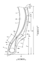
- FIG. 1 is a meridional sectional view of a main part of a run-flat tire according to the present embodiment.
- FIG. 2 is a detailed view of the vicinity of the bead portion in FIG.
- FIG. 3A is a chart showing the results of a performance evaluation test of a run flat tire.
- FIG. 3B is a chart showing the results of the performance evaluation test of the run flat tire.
- FIG. 3C is a chart showing the results of the performance evaluation test of the run flat tire.
- FIG. 3D is a chart showing the results of the performance evaluation test of the run flat tire.
- FIG. 1 is a meridional sectional view of a main part of a run flat tire 1 according to the present embodiment.
- the tire radial direction means a direction orthogonal to the tire rotation axis (not shown) of the run flat tire 1 configured as a pneumatic tire
- the tire radial direction inner side means the tire rotation axis in the tire radial direction.
- To the outer side in the tire radial direction means the side away from the tire rotation axis in the tire radial direction.
- the tire circumferential direction means a circumferential direction with the tire rotation axis as the central axis.
- the tire width direction means a direction parallel to the tire rotation axis
- the tire width direction inner side is a side facing the tire equatorial plane (tire equatorial line) CL in the tire width direction
- the tire width direction outer side is the tire width direction.
- the tire equatorial plane CL is a plane orthogonal to the tire rotation axis of the run flat tire 1 and passing through the center of the tire width of the run flat tire 1.
- the tire width is the width in the tire width direction between the outermost portions in the tire width direction, that is, the distance between the portions farthest from the tire equatorial plane CL in the tire width direction.
- the tire equatorial line is a line on the tire equatorial plane CL and extending along the tire circumferential direction of the run flat tire 1.
- the tire equatorial line is designated by the same reference numeral “CL” as the tire equatorial plane.
- the run-flat tire 1 of the present embodiment has a tread portion 2, shoulder portions 3 located on both sides of the tread portion 2 in the tire width direction, and sidewall portions 4 sequentially continuous from each shoulder portion 3. And a bead portion 5.
- the run flat tire 1 also includes a carcass 6, a belt layer 7, a belt cover 8, an inner liner 9, and a side reinforcing rubber layer 10.
- the tread portion 2 has a tread rubber 2A, which is a rubber member, and is exposed at the outermost side in the tire radial direction of the run flat tire 1.
- the surface of the tread portion 2 constitutes a part of the contour of the run flat tire 1.
- a tread surface 21 is formed on the outer peripheral surface of the tread portion 2, that is, on the tread surface that comes into contact with the road surface during traveling.
- the tread surface 21 is provided with a plurality of main grooves 22 which are straight main grooves extending in the tire circumferential direction and parallel to the tire equator line CL.
- the tread surface 21 also includes a plurality of main grooves 22. Thereby, a plurality of land portions 23 extending along the tire circumferential direction are formed.
- the main groove 22 may be formed to be bent or curved in the tire width direction while extending along the tire circumferential direction.
- the tread surface 21 is provided with a lug groove 24 extending in the land portion 23 in a direction intersecting with the tire circumferential direction.
- the lug groove 24 may communicate with the main groove 22, or at least one end thereof may not communicate with the main groove 22 and may terminate in the land portion 23.
- the land portion 23 is formed in a block shape divided by the main groove 22 and the lug groove 24 in the tire width direction and the tire circumferential direction, respectively.
- the lug groove 24 may be formed so as to extend in the tire width direction and be inclined in the tire circumferential direction, or to be bent or curved in the tire circumferential direction while extending in the tire width direction.
- the shoulder portion 3 is a portion on both sides in the tire width direction of the tread portion 2, and is made of a tread rubber 2A which is a rubber material forming the tread portion 2.
- a pair of sidewall portions 4 is arranged by being arranged on both sides of the tread portion 2 in the tire width direction, and the pair of sidewall portions 4 extend from the shoulder portion 3 to the inner side in the tire radial direction. Is formed.
- the sidewall portion 4 formed in this way is a portion exposed to the outermost side in the tire width direction of the run flat tire 1, and has a side rubber 4A that is a rubber material.
- the bead portions 5 are arranged inside the respective sidewall portions 4 in the radial direction of the tire, that is, the bead portions 5 are arranged in a pair like the sidewall portions 4.
- a bead core 50 and a first bead filler 51 are arranged in each of the pair of bead portions 5.
- the second bead filler 52 is arranged from the position where the bead portion 5 is arranged in the tire radial direction toward the tire radial outside.
- the bead core 50 is formed by winding a bead wire which is a steel wire in a ring shape.
- the first bead filler 51 is a rubber member arranged along the carcass 6, and has a JIS-A hardness at 20 ° C. of 68 or more and 99 or less.
- JIS-A hardness in this case is the durometer hardness measured at a temperature of 20 ° C. using an A type durometer according to JIS K-6253.
- the carcass 6 is bridged in a toroidal shape between the bead portions 5 arranged on both sides in the tire width direction to form the skeleton of the run flat tire 1. Specifically, the carcass 6 is arranged from one bead portion 5 to the other bead portion 5 of the pair of bead portions 5 located on both sides in the tire width direction, and the vicinity of both end portions of the carcass 6 is a bead core.
- the bead portion 5 is folded back in the tire width direction through the inside of the bead core 50 in the tire radial direction so as to wrap the 50 and the first bead filler 51.
- the carcass 6 extends from the tread portion 2 to the bead portion 5 via the sidewall portion 4 and is formed continuously from the carcass body portion 6a and the carcass body portion 6a which are bridged between the pair of bead portions 5. It has a turn-up portion 6b folded back outward in the width direction.
- the turn-up portion 6b is formed continuously from the carcass body portion 6a, and passes from the tire width direction inner side of the bead core 50 to the tire radial direction inner side of the bead core 50 at the bead portion 5 to the tire width direction outer side of the bead core 50.
- the carcass body portion 6a is folded back and overlapped with the bead core 50 on the outer side in the tire radial direction.
- the carcass 6 formed in this way is formed by coating a carcass cord made of steel or an organic fiber such as aramid, nylon, polyester, or rayon with coating rubber and rolling the carcass cord.
- the carcass cord of the carcass 6 is provided so as to extend along the tire meridian direction and have an inclination angle in the tire circumferential direction within a predetermined range.
- the carcass cords of the carcass 6 are arranged such that a carcass angle defined as an inclination angle in the longitudinal direction of the carcass cord with respect to the tire circumferential direction is within a range of 80 ° or more and 90 ° or less. They are installed side by side.
- the first bead filler 51 included in the bead portion 5 is arranged inside the turn-up portion 6b of the carcass 6 in the tire width direction and outside the bead core 50 in the tire radial direction.
- the first bead filler 51 is arranged on the tire radial direction outer side of the bead core 50 in a portion defined by the carcass body portion 6a and the turn-up portion 6b of the carcass 6 and the bead core 50 in the tire meridional section. There is.
- the second bead filler 52 is arranged along the carcass 6 on the outer side in the tire width direction of the turnup portion 6b of the carcass 6. That is, the second bead filler 52 is arranged so as to be sandwiched between the turnup portion 6b of the carcass 6 and the side rubber 4A in the tire width direction.
- the outer end portion 52a of the second bead filler 52 in the tire radial direction is located on the outer side in the tire radial direction with respect to the outer end portion 51a of the first bead filler 51 in the tire radial direction, and the tire diameter of the second bead filler 52.
- the inner end portion 52b in the direction is located inward of the outer end portion 51a of the first bead filler 51 in the tire radial direction.
- the second bead filler 52 thus arranged is made of a rubber material and has a JIS-A hardness at 20 ° C. of 69 or more and 94 or less.
- the turnup portion 6b of the carcass 6 has an end portion 6c in the tire radial direction located outside the first bead filler 51 in the tire radial direction. Therefore, the turn-up portion 6b is provided so as to cover the entire first bead filler 51 and extend from the bead portion 5 toward the sidewall portion 4.
- the bead portion 5 has a rim cushion rubber 5A that is a rubber member exposed at a tire outer side portion that comes into contact with a rim (not shown).
- the rim cushion rubber 5A forms the outer periphery of the bead portion 5, and the second bead disposed on the tire width direction outer side of the carcass 6 from the tire width direction inner side of the bead portion 5 to the tire radial direction inner side that contacts the rim.
- the filler 52 is arranged so as to cover a part of the inner portion in the tire radial direction.
- the belt layer 7 is configured by stacking a plurality of belt plies 71 and 72 in the tire radial direction, is arranged outside the carcass 6 in the tire radial direction, and is laid around the outer periphery of the carcass 6.
- the belt layer 7 has two layers of belt plies 71 and 72.
- the two-layer belt plies 71, 72 are formed by coating a plurality of belt cords made of steel or an organic fiber material with coating rubber and rolling the belt cords.
- the belt plies 71, 72 extend in the tire width direction relative to the tire circumferential direction.
- the belt angle which is the inclination angle, is in the range of 20 ° or more and 35 ° or less.
- the two layers of belt plies 71, 72 have a so-called cross ply structure in which the belt angles have mutually different signs, and the extending directions of the belt cords intersect each other. That is, in the two-layer belt plies 71 and 72, the inclination directions of the belt cords in the tire width direction with respect to the tire circumferential direction are opposite to each other.
- a belt cover 8 is arranged outside the belt layer 7 in the tire radial direction.
- the belt cover 8 is formed by rolling a plurality of cords made of steel or organic fiber material coated with coat rubber, and the belt angle in the tire width direction with respect to the tire circumferential direction is within ⁇ 5 °. .. Further, the belt cover 8 is disposed on the outer side in the tire radial direction of the belt layer 7 so as to be laminated on the belt plies 71 and 72, and the belt plies 71 and 72 of the belt layer 7 are disposed at least in the tire width direction. It is arranged in the range.
- the belt cover 8 has a belt full cover 81 that entirely covers the belt layer 7 and a belt edge cover 82 that covers the tire width direction end of the belt layer 7.
- the belt edge cover 82 is provided, for example, by winding a strip-shaped strip material having a width of about 10 mm in the tire circumferential direction.
- the configuration of the belt cover 8 is not limited to the above. For example, only the belt full cover 81 is arranged, only the belt edge cover 82 is arranged, or the belt full cover 81 and the belt edge cover 82 are arranged in plural. You may.
- the inner liner 9 is an air permeation preventive layer that is disposed on the tire inner surface 11 that is the inner surface of the tire of the run flat tire 1 and covers the carcass 6.
- the inner liner 9 prevents the air filled in the run flat tire 1 from leaking, and Suppresses oxidation due to the exposure of the carcass 6.
- the inner liner 9 is arranged on the tire inner surface 11 side of the carcass 6 and has both end portions in the tire width direction reaching the position of the pair of bead portions 5, and is wound around the tire circumferential direction in a toroidal shape. Has been placed.
- the side reinforcing rubber layer 10 is a rubber member provided inside the sidewall portion 4, and is disposed without being exposed on the tire inner surface 11 or the tire outer surface of the run flat tire 1. Specifically, the side reinforcing rubber layer 10 is mainly located on the tire width direction inner side of a portion of the carcass 6 located in the sidewall portion 4, and is disposed between the carcass 6 and the inner liner 9 in the sidewall portion 4. Has been done. That is, the side reinforcing rubber layer 10 is arranged on the tire inner surface 11 side of the carcass 6 in the sidewall portion 4.
- the side reinforcing rubber layer 10 is formed in a crescent shape in which the tire meridional section is convex outward in the tire width direction.
- the side reinforcing rubber layer 10 formed in the crescent shape has an outer end 10a, which is an outer end in the tire radial direction, located inside the belt layer 7 in the tread portion 2 in the tire radial direction. Therefore, the side reinforcing rubber layer 10 is arranged so that a predetermined range near the outer end portion 10a overlaps the belt layer 7 in the tire radial direction.
- the inner end portion 10b which is the inner end portion in the tire radial direction of the side reinforcing rubber layer 10, is located on the tire radial direction outer side than the position of the bead core 50 in the bead portion 5 in the tire radial direction, and the first bead filler is used. It is located on the inner side in the tire radial direction with respect to the outer end portion 51 a of 51. Further, the inner end portion 10b of the side reinforcing rubber layer 10 is located outside the inner end portion 52b of the second bead filler 52 in the tire radial direction.
- the side reinforcing rubber layer 10 formed in a crescent shape in the meridional section of the run-flat tire 1 has a maximum thickness GRmax from a rim diameter reference position BL that is a reference position on the tire radial direction inner side of the tire section height SH. It is located outside the tire radial direction within the range of 40% or more and 70% or less of the tire cross-section height SH.
- the maximum thickness GRmax of the side reinforcing rubber layer 10 is in the range of 6.0 mm or more and 11.5 mm or less.
- the tire cross-section height SH in this case is the distance in the tire radial direction between the rim diameter reference position BL and the portion of the tread portion 2 that is located on the outermost side in the tire radial direction.
- the rim diameter reference position BL here is a tire axial direction line that passes through the rim diameter defined by the JATMA standard.
- the tire cross-section height SH is obtained by assembling the runflat tire 1 on the regular rim, filling the regular internal pressure, and applying no load to the runflat tire 1 and the tire outer diameter and the rim. Half of the difference from the diameter.
- the regular rim referred to here is a "standard rim” specified by JATMA, "Design Rim” specified by TRA, or “Measuring Rim” specified by ETRTO.
- the normal internal pressure is the "maximum air pressure” specified by JATMA, the maximum value described in "TIRE LOAD LIMITS AT VARIOUS COLD INFLATION PRESSURES" specified by TRA, or “INFLATION PRESSURES" specified by ETRTO.
- the tire cross-section height SH defined in this way is 100 mm or more. More specifically, the run-flat tire 1 according to the present embodiment has a tire cross-section height SH within a range of 100 mm or more and 140 mm or less.
- the side reinforcing rubber layer 10 is formed of a rubber material having higher strength than the side rubber 4A forming the sidewall portion 4 and the rim cushion rubber 5A forming the bead portion 5.
- the side rubber 4A has a JIS-A hardness at 20 ° C. in the range of 50 to 59
- the rim cushion rubber 5A has a JIS-A hardness at 20 ° C. of 66 to 74. It is within the following range.
- the side-reinforcing rubber layer 10 has a JIS-A hardness at 20 ° C. of 72 or more and 82 or less.
- FIG. 2 is a detailed view of the vicinity of the bead portion 5 in FIG.
- the first bead filler 51 and the second bead filler 52 are arranged such that the height in the tire radial direction is within a predetermined range with respect to the tire cross-section height SH.
- the first bead filler height H BFL which is the height in the tire radial direction from the rim diameter reference position BL to the outer end portion 51a of the first bead filler 51, is the tire cross section. It is less than 30% of the height SH.
- the second bead filler height H 2FL which is the height in the tire radial direction from the rim diameter reference position BL to the outer end portion 52a of the second bead filler 52, is the tire cross-section height SH. More than 50% of the total. Further, the first bead filler 51 and the second bead filler 52 have a difference between the first bead filler height H BFL and the second bead filler height H 2FL of 30% or more of the tire cross-section height SH. There is.
- the first bead filler height H BFL is preferably in the range of 23% or more and 30% or less of the tire cross-section height SH, and the second bead filler height H 2FL is 50% of the tire cross-section height SH. It is preferably within the range of 60% to 60%.
- the second bead filler height H 2FL is preferably in the range of 180% or more and 250% or less of the first bead filler height H BFL .
- the first bead filler height H BFL is preferably in the range of 24 mm or more and 33 mm or less
- the second bead filler height H 2FL is preferably in the range of 54 mm or more and 78 mm or less.
- the first bead filler 51 has the outer end portion 51 a located on the outer side in the tire radial direction with respect to the inner end portion 10 b of the side reinforcing rubber layer 10. It is arranged so as to overlap the reinforcing rubber layer 10 in the tire radial direction. That is, the first bead filler 51 overlaps the side reinforcing rubber layer 10 in the tire radial direction with the carcass body portion 6a, which is a portion located inside the first bead filler 51 in the tire width direction, in the carcass 6, The side reinforcing rubber layer 10 is arranged to overlap in the tire width direction with the carcass body 6a interposed therebetween.
- the second bead filler 52 has the inner end portion 52b located on the inner side in the tire radial direction with respect to the outer end portion 51a of the first bead filler 51. It is arranged so as to overlap the one bead filler 51 in the tire radial direction. That is, the second bead filler 52 overlaps the first bead filler 51 in the tire radial direction via the turn-up portion 6b, which is a portion of the carcass 6 located outside the first bead filler 51 in the tire width direction, The first bead filler 51 is arranged to overlap with the first bead filler 51 in the tire width direction through the turn-up portion 6b.
- the side reinforcing rubber layer 10 and the first bead filler 51 that overlap with each other via the carcass 6 have an overlap amount L RFL within a range of 20% or more and 50% or less of the first bead filler height H BFL.
- the overlap amount L RFL is the linear distance between the inner end 10b of the side reinforcing rubber layer 10 and the outer end 51a of the first bead filler 51 in the tire meridional section.
- the first bead filler 51 and the second bead filler 52 that overlap with each other via the carcass 6 have an overlap amount L 2FL within a range of 40% or more and 70% or less of the first bead filler height H BFL. Is becoming The overlap amount L2FL in this case is a linear distance between the outer end portion 51a of the first bead filler 51 and the inner end portion 52b of the second bead filler 52 in the tire meridional section.
- the side reinforcing rubber layer 10 and the first bead filler 51 preferably have an overlap amount L RFL in a range of 8 mm or more and 16 mm or less, and the first bead filler 51 and the second bead filler 52 are overlaid. It is preferable that the lapping amount L 2FL is within a range of 10 mm or more and 20 mm or less.
- the side reinforcing rubber layer 10, the first bead filler 51, and the second bead filler 52 have a first bead filler 51 and a second bead filler 52 that are more than the overlap amount L RFL of the side reinforcing rubber layer 10 and the first bead filler 51. It is preferable that the overlap amount L 2FL with the two bead filler 52 is larger than that of the two bead filler 52.
- the first bead filler 51 has a thickness that decreases from the inner side to the outer side in the tire radial direction.
- the second bead filler 52 becomes thinner near the outer end 52a in the vicinity of the outer end 52a, and becomes thinner near the inner end 52b in the vicinity of the inner end 52b. ..
- the second bead filler 52 which becomes thinner near both ends in the tire radial direction, has a maximum thickness G2max in the range of 2.5 mm or more and 6.5 mm or less.
- the second bead filler 52 is a maximum thickness G2max position, located within the range of 40% to 85% or less of the second bead filler height H 2FL from the rim diameter reference position BL on the outer side in the tire radial direction There is.
- the first bead filler 51 and the second bead filler 52 arranged as described above have a cross-sectional area S 2FL of the second bead filler 52 that is larger than a cross-sectional area S BFL of the first bead filler 51 in the tire meridional cross section. Is getting bigger.
- the cross-sectional area S 2FL of the second bead filler 52 in the tire meridional section is the cross-sectional area S BFL of the first bead filler 51 in the tire meridional section. It is in the range of 150% or more and 400% or less.
- the cross-sectional area S 2FL of the second bead filler 52 in the tire meridional section is preferably in the range of 150% to 200% of the cross-sectional area S BFL of the first bead filler 51 in the tire meridional section.
- the side reinforcing rubber layer 10, the first bead filler 51, and the second bead filler 52 are the side reinforcing rubber layer 10, the first bead filler 51, and the second bead located on one side in the tire width direction with respect to the tire equatorial plane CL.
- the relationship between the total cross-sectional area S ALL of the filler 52 and the tire cross-section height SH and the load index LI of the runflat tire 1 is (0.16 ⁇ SH ⁇ LI-1100) ⁇ S ALL It satisfies ⁇ (0.16 ⁇ SH ⁇ LI-800).
- the sum S SALL of the cross-sectional areas in this case is, in detail, the side reinforcing rubber layer 10, the first bead filler 51, the second bead filler 52, and the tire equatorial plane which are located on both sides of the tire equatorial plane CL in the tire width direction. It is the sum of the sectional areas of the portions located on one side of CL and located on one side in the tire radial direction with respect to the tire rotation axis in the tire meridional section.
- the tire cross-section height SH uses a value whose unit is mm
- the total cross-sectional area S ALL uses a value whose unit is mm 2 .
- load index LI here is an index that represents the load capacity of the tire, and is either the "load index” specified by JATMA or the "Load Index” specified by ETRTO.
- the load index LI includes both the ETRTO standard and the extra load standard.
- the side reinforcing rubber layer 10, the first bead filler 51, and the second bead filler 52 have a modulus MRFL at 100% extension of the side reinforcing rubber layer 10 and a modulus at 100% extension of the first bead filler 51.
- M BFL and the modulus M 2FL of the second bead filler 52 at the time of 100% elongation satisfy the relationship of M BFL > M RFL > M 2FL .
- the modulus M 2FL of the second bead filler 52 at the time of 100% elongation is in the range of 5.3 MPa or more and 6.1 MPa or less.
- the modulus at 100% elongation in this case is measured by a tensile test at 23 ° C. according to JIS K6251 (using dumbbell No. 3), and shows the tensile stress at 100% elongation.
- the modulus M RFL at 100% elongation of these side-reinforcing rubber layer 10 and the modulus M BFL at 100% elongation of the first bead filler 51, the modulus M 2FL at 100% elongation of the second bead filler 52 And preferably satisfy the relationship of (2.0 ⁇ M 2FL )> M BFL > M RFL > (1.5 ⁇ M 2FL ).
- the run flat tire 1 When the run flat tire 1 according to the present embodiment is mounted on a vehicle, the run flat tire 1 is rim-assembled to the rim wheel by fitting the rim wheel to the bead portion 5, and the inside is filled with air. Attach it to the vehicle in the state of fretting.
- the runflat tire 1 rotates while the tread surface 21 of the lower part of the tread surface 21 contacts the road surface.
- the vehicle travels by transmitting a driving force or a braking force to the road surface or generating a turning force by a frictional force between the tread surface 21 and the road surface.
- the power generated by a prime mover such as an engine of the vehicle is transmitted to the rim wheel, transmitted from the rim wheel to the bead portion 5, and transmitted to the run flat tire 1.
- the run-flat tire 1 receives a large load due to the urging force from the inside to the outside due to the air filled inside as described above, and the sidewall portion 4 and the like are appropriately bent. By traveling, the vehicle can travel while ensuring a comfortable ride.
- the internal air may leak due to, for example, a puncture caused by a foreign substance sticking to the tread surface 21.
- the air pressure decreases, and the biasing force of the air from the inside to the outside of the runflat tire 1 decreases, so that it becomes difficult for the internal air pressure to receive the load when the vehicle is running. ..
- the run-flat tire 1 according to the present embodiment can receive a part of the load that is difficult to receive due to the air pressure by the side reinforcing rubber layer 10 provided in the sidewall portion 4. .
- the side reinforcing rubber layer 10 is formed of a rubber material having higher strength than the side rubber 4A forming the sidewall portion 4, even when a large load in the tire radial direction acts on the sidewall portion 4,
- the side reinforcing rubber layer 10 can suppress deformation of the sidewall portion 4 in the tire radial direction.
- the side reinforcing rubber layer 10 is arranged so that a portion near the outer end 10a overlaps with the belt layer 7, and the vicinity of the inner end 10b is disposed with the first bead filler 51 and the tire radial direction via the carcass 6. Are overlapped with each other. Therefore, the side reinforcing rubber layer 10 can appropriately receive the load acting in the tire radial direction between the tread portion 2 and the bead portion 5, and reduce the load acting on the side rubber 4A to reduce the stress of the side rubber 4A. Can be reduced.
- a second bead filler 52 is arranged on the outer side in the tire width direction of the turn-up portion 6b of the carcass 6, and the second bead filler 52 is arranged in the tire radial direction with the first bead filler 51 via the carcass 6. It is arranged to overlap.
- the second bead filler 52 has a second bead filler height H 2FL of 50% or more of the tire cross-sectional height SH, so that the second bead filler 52 is located from the position of the bead portion 5 in the tire radial direction to the side.
- the wall portion 4 is arranged over a wide range in the tire radial direction.
- the rigidity from the bead portion 5 to the sidewall portion 4 is also enhanced by the second bead filler 52, and a part of the load acting in the tire radial direction between the tread portion 2 and the bead portion 5 is The second bead filler 52 can also be received.
- the run-flat tire 1 can prevent the sidewall portion 4 from being excessively bent due to the weight of the vehicle even when the internal air pressure is reduced, and the run-flat running is a run in a state where air leaks. It can be performed.
- the run-flat tire 1 is capable of run-flat running in such a way that it is equivalent to an unloaded condition in which the internal pressure is set to 0 kPa when mounted on the regular rim, or an internal pressure is set to 0 kPa when assembled in the regular rim. Then, the position of each bead portion 5 is set to the position assembled to the regular rim.
- the side-reinforcing rubber layer 10 is thus arranged in the sidewall portion 4 to enable the run-flat traveling. Since the rubber material forming the rubber layer 10 has higher strength than the rubber material forming the side rubber 4A, the rigidity of the sidewall portion 4 in the tire radial direction may be too high. If the rigidity of the sidewall portion 4 in the tire radial direction becomes too high, the sidewall portion 4 is less likely to bend in the tire radial direction during normal traveling with the inside of the run-flat tire 1 filled with air, so that the ride comfort is improved. There is a risk that it will become worse.
- the first bead filler height H BFL is 30% or less of the tire cross-section height SH, so the rigidity of the first bead filler 51 in the tire radial direction is high. It can be suppressed from becoming too much. As a result, it is possible to prevent the rigidity of the sidewall portion 4 and the bead portion 5 in the tire radial direction from becoming too high, so that it is possible to suppress deterioration of the riding comfort.
- the side reinforcing rubber layer 10 and the first bead filler 51 are arranged so as to overlap with each other via the carcass 6, and the first bead filler 51 and the second bead filler 52 also overlap with each other via the carcass 6. Since they are arranged, the increase in rigidity in the tire radial direction can be suppressed. That is, the side reinforcing rubber layer 10 and the first bead filler 51 are separated by the carcass body portion 6a, and the first bead filler 51 and the second bead filler 52 are separated by the turn-up portion 6b. It is possible to relatively easily deform each other in the tire radial direction. As a result, when a load in the tire radial direction acts on the sidewall portion 4, it is possible to promote flexural deformation in the tire radial direction, and suppress deterioration of riding comfort.
- the cross-sectional area S 2FL of the second bead filler 52 in the meridional section of the tire is within the range of 150% or more and 400% or less of the cross-sectional area S BFL of the first bead filler 51 in the meridional section of the tire, during normal traveling. It is possible to secure the rigidity during run-flat traveling while suppressing the deterioration of the riding comfort in. That is, when the cross-sectional area S 2FL of the second bead filler 52 is less than 150% of the cross-sectional area S BFL of the first bead filler 51, even if the second bead filler 52 is provided, the bead portion 5 to the sidewall portion are provided.
- the second bead filler 52 It becomes difficult for the second bead filler 52 to effectively increase the rigidity up to 4.
- the cross-sectional area S 2FL of the second bead filler 52 is larger than 400% of the cross-sectional area S BFL of the first bead filler 51, the rigidity from the bead portion 5 to the sidewall portion 4 is the second bead filler 52. It becomes too high and it becomes difficult to control the deterioration of riding comfort.
- the cross-sectional area S 2FL of the second bead filler 52 is in the range of 150% or more and 400% or less of the cross-sectional area S BFL of the first bead filler 51, from the bead portion 5 to the sidewall portion 4
- the rigidity can be effectively increased by the second bead filler 52 while suppressing the rigidity of the second bead from becoming too high.
- the ride comfort during normal driving It is possible to secure the rigidity during run-flat traveling while suppressing the deterioration of That is, when S ALL ⁇ (0.16 ⁇ SH ⁇ LI-1100), the total cross-sectional area S ALL of the side reinforcing rubber layer 10, the first bead filler 51, and the second bead filler 52 is too small. Even if the side reinforcing rubber layer 10 and the second bead filler 52 are provided, it is difficult to effectively increase the rigidity from the bead portion 5 to the sidewall portion 4.
- the rigidity of the bead portion 5 can be more reliably ensured. That is, when the first bead filler height H BFL is less than 23% of the tire cross-section height SH, the first bead filler height H BFL is too low, and thus it is difficult to secure the rigidity of the first bead filler 51. There is a risk of becoming. In this case, it becomes difficult to secure the rigidity of the bead portion 5, and it may be difficult to secure the rigidity during run-flat traveling.
- the rigidity of the first bead filler 51 can be ensured more reliably, and the bead portion can be more reliably produced.
- the rigidity of 5 can be secured.
- the second bead filler height H 2FL is within the range of 50% or more and 60% or less of the tire cross-section height SH, it is more likely that the rigidity from the bead portion 5 to the sidewall portion 4 becomes too high. It can be surely suppressed. That is, when the second bead filler height H 2FL is larger than 60% of the tire cross-sectional height SH, the range in which the second bead filler 52 is arranged in the sidewall portion 4 is too large, and therefore the bead portion 5 to the side portion There is a risk that the rigidity of the wall portion 4 will become too high.
- the second bead filler height H 2FL is 60% or less of the tire cross-section height SH, it is possible to prevent the range in which the second bead filler 52 is arranged from becoming too large, It is possible to more reliably prevent the rigidity from the bead portion 5 to the sidewall portion 4 to become too high.
- the second bead filler height H 2FL is within the range of 180% or more and 250% or less of the first bead filler height H BFL , run-flat traveling is suppressed while suppressing deterioration of the riding comfort during normal traveling.
- the rigidity at the time can be secured. That is, when the second bead filler height H 2FL is less than 180% of the first bead filler height H BFL , the second bead filler height H 2FL is too low, so the second bead filler 52 is provided. However, the rigidity from the bead portion 5 to the sidewall portion 4 may not be effectively increased even by the second bead filler 52.
- the second bead filler height H 2FL is larger than 250% of the first bead filler height H BFL , the second bead filler height H 2FL is too high, and therefore the bead portion 5 to the sidewall portion 4 The rigidity of the second bead filler 52 becomes too high, which may make it difficult to suppress deterioration of riding comfort.
- the second bead filler height H 2FL is in the range of 180% or more and 250% or less of the first bead filler height H BFL , the rigidity from the bead portion 5 to the sidewall portion 4 is high.
- the rigidity in this range can be appropriately increased by the second bead filler 52 while more reliably suppressing excessive increase. As a result, it is possible to more surely secure the rigidity during the run-flat traveling while suppressing the deterioration of the riding comfort during the normal traveling.
- the cross-sectional area S 2FL of the second bead filler 52 in the meridional section of the tire is within the range of 150% or more and 200% or less of the cross-sectional area S BFL of the first bead filler 51 in the meridional section of the tire, during normal traveling. It is possible to more reliably suppress the deterioration of the riding comfort in the vehicle. That is, by setting the cross-sectional area S 2FL of the second bead filler 52 to be 200% or less of the cross-sectional area S BFL of the first bead filler 51, the rigidity from the bead portion 5 to the sidewall portion 4 can be increased. It is possible to more reliably prevent the temperature from becoming too high. As a result, it is possible to more reliably suppress the deterioration of riding comfort during normal traveling. As a result, the run-flat durability and the ride comfort performance can be more reliably achieved at the same time.
- the overlap amount L RFL between the side reinforcing rubber layer 10 and the first bead filler 51 is within the range of 20% or more and 50% or less of the first bead filler height H BFL. It is possible to secure rigidity during run-flat traveling while suppressing deterioration of riding comfort during use. That is, since the overlap amount L RFL is, if less than 20% of the first bead filler height H BFL is the overlap amount L RFL between the side reinforcing rubber layer 10 and the first bead filler 51 is too small, the side There is a possibility that it may be difficult to increase the rigidity of the portion where the reinforcing rubber layer 10 and the first bead filler 51 overlap.
- the side reinforcing rubber layer 10 is provided on the sidewall portion 4, it may be difficult to effectively increase the rigidity near the bead portion 5.
- the side reinforcement is too large because the overlap amount L RFL between the side reinforcing rubber layer 10 and the first bead filler 51 is too large.
- the rigidity of the portion where the rubber layer 10 and the first bead filler 51 overlap may be too high. In this case, the rigidity in the vicinity of the bead portion 5 may be too high.
- the overlap amount L RFL is in the range of 20% or more and 50% or less of the first bead filler height H BFL , it is possible to more reliably prevent the rigidity near the bead portion 5 from becoming too high.
- the rigidity in the vicinity of the bead portion 5 can be appropriately increased by the side reinforcing rubber layer 10. As a result, it is possible to more surely secure the rigidity during the run-flat traveling while suppressing the deterioration of the riding comfort during the normal traveling.
- the overlap amount L 2FL of the first bead filler 51 and the second bead filler 52 is within the range of 40% or more and 70% or less of the first bead filler height H BFL , it is possible to more reliably perform normal traveling. It is possible to secure rigidity during run-flat traveling while suppressing deterioration of riding comfort during use. That is, since the overlap amount L 2FL is, if less than 20% of the first bead filler height H BFL is the overlap amount L 2FL the first bead filler 51 and the second bead filler 52 is too small, the There is a possibility that it may be difficult to increase the rigidity of the portion where the first bead filler 51 and the second bead filler 52 overlap.
- the second bead filler 52 is provided in the sidewall portion 4, it may be difficult to effectively increase the rigidity near the bead portion 5.
- the overlap amount L 2FL is, when greater than 70% of the first bead filler height H BFL is the overlap amount L 2FL the first bead filler 51 and the second bead filler 52 is too large, the first There is a risk that the rigidity of the portion where the bead filler 51 and the second bead filler 52 overlap becomes too high. In this case, the rigidity in the vicinity of the bead portion 5 may be too high.
- the overlap amount L 2FL is within the range of 40% or more and 70% or less of the first bead filler height H BFL , it is possible to more reliably prevent the rigidity near the bead portion 5 from becoming too high.
- the rigidity in the vicinity of the bead portion 5 can be appropriately increased by the second bead filler 52. As a result, it is possible to more surely secure the rigidity during the run-flat traveling while suppressing the deterioration of the riding comfort during the normal traveling. As a result, the run-flat durability and the ride comfort performance can be more reliably achieved at the same time.
- the overlap amount L RFL of the side reinforcing rubber layer 10 and the first bead filler 51 is in the range of 8 mm or more and 16 mm or less, it is possible to more reliably suppress the deterioration of the riding comfort during normal running, and It is possible to secure rigidity during flat traveling. That is, when the overlap amount L RFL is less than 8 mm, the side reinforcing rubber layer 10 is provided on the sidewall portion 4 because the overlap amount L RFL between the side reinforcing rubber layer 10 and the first bead filler 51 is too small. However, it may be difficult to effectively increase the rigidity in the vicinity of the bead portion 5.
- the overlap amount L RFL is larger than 16mm, since the overlap amount L RFL between the side reinforcing rubber layer 10 and the first bead filler 51 is too large, there is a possibility that the rigidity of the vicinity of the bead portion 5 becomes too high ..
- the reinforcing rubber layer 10 can appropriately increase the rigidity, and it is possible to secure rigidity during run-flat traveling while suppressing deterioration of riding comfort during normal traveling.
- the overlap amount L 2FL of the first bead filler 51 and the second bead filler 52 is in the range of 10 mm or more and 20 mm or less, the run comfort can be more reliably suppressed while suppressing the deterioration of the riding comfort during normal traveling. It is possible to secure rigidity during flat traveling. That is, if the overlap amount L 2FL is less than 10mm, since the overlap amount L 2FL the first bead filler 51 and the second bead filler 52 is too small, the second bead filler 52 provided in the side wall portions 4 However, it may be difficult to effectively increase the rigidity in the vicinity of the bead portion 5.
- the overlap amount L 2FL is larger than 20mm, since the overlap amount L 2FL the first bead filler 51 and the second bead filler 52 is too large, there is a possibility that the rigidity of the vicinity of the bead portion 5 becomes too high ..
- the overlap amount L 2FL is in the range of 10 mm or more and 20 mm or less, it is possible to more reliably suppress the rigidity near the bead portion 5 from becoming excessively high, and the rigidity near the bead portion 5
- the 2-bead filler 52 can be appropriately increased, and the rigidity during run-flat traveling can be secured while suppressing the deterioration of the riding comfort during normal traveling. As a result, the run-flat durability and the ride comfort performance can be more reliably achieved at the same time.
- the modulus M RFL at 100% elongation of the side reinforcing rubber layer 10 and the modulus M BFL at 100% elongation of the first bead filler 51, and a 100% elongation when the modulus M 2FL the second bead filler 52 , M BFL > M RFL > M 2FL , it is possible to more reliably secure the rigidity during run-flat traveling while suppressing deterioration of the riding comfort during normal traveling.
- the rigidity of the vicinity of the bead portion 5 by a first bead filler 51 It can be increased more reliably.
- the modulus M 2FL of the second bead filler 52 at the time of 100% extension is smaller than the modulus M RFL of the side reinforcing rubber layer 10 at the time of 100% extension, even if the second bead filler 52 is provided, the bead portion 5 is formed. It is possible to prevent the rigidity in the vicinity from becoming too high, and it is possible to ensure the flexibility of bending from the bead portion 5 to the sidewall portion 4. As a result, it is possible to more reliably ensure the rigidity during run-flat traveling while suppressing the deterioration of the riding comfort during normal traveling. As a result, the run-flat durability and the ride comfort performance can be more reliably achieved at the same time.
- the modulus M RFL at 100% elongation of the side reinforcing rubber layer 10 and the modulus M BFL at 100% elongation of the first bead filler 51, and a 100% elongation when the modulus M 2FL the second bead filler 52 , (2.0 ⁇ M 2FL )> M BFL > M RFL > (1.5 ⁇ M 2FL ), it is possible to more reliably suppress deterioration of the riding comfort during normal driving and to run flat. The rigidity of can be secured.
- the modulus M BFL of the first bead filler 51 at the time of 100% extension is smaller than twice the modulus M 2FL of the second bead filler 52 at the time of 100% extension, the rigidity near the bead portion 5 becomes high. It is possible to prevent the beads from passing through, and it is possible to secure the flexibility of bending from the bead portion 5 to the sidewall portion 4. Since the modulus MRFL of the side reinforcing rubber layer 10 at 100% extension is smaller than 1.5 times the modulus M2FL of the second bead filler 52 at 100% extension, the rigidity of the sidewall portion 4 is The reinforcing rubber layer 10 can ensure more reliably. As a result, it is possible to more reliably ensure the rigidity during run-flat traveling while suppressing the deterioration of the riding comfort during normal traveling. As a result, the run-flat durability and the ride comfort performance can be more reliably achieved at the same time.
- the run-flat tire 1 since the tire cross-section height SH is 100 mm or more, the sidewall portion 4 tends to bend easily, and in order to increase the run-flat durability, It is necessary to increase the rigidity of the sidewall portion 4 in the tire radial direction. However, when the rigidity of the sidewall portion 4 is increased, it may be difficult to reduce the deterioration of riding comfort during normal traveling. Therefore, in the run flat tire 1 according to the present embodiment, the second bead filler 52 that overlaps the first bead filler 51 is arranged, and the first bead filler height H BFL and the second bead filler height H 2FL are predetermined.
- the cross-sectional area S 2FL of the side reinforcing rubber layer 10, the first bead filler 51, and the second bead filler 52 is within a predetermined range.
- the first bead filler 51 has the first bead filler height H BFL within the range of 24 mm or more and 33 mm or less, it is possible to more reliably suppress the deterioration of the riding comfort during normal traveling, and at the same time during run-flat traveling.
- the rigidity can be secured. That is, when the first bead filler height H BFL is less than 24 mm, the first bead filler height H BFL is too low, and thus it may be difficult to secure the rigidity of the first bead filler 51. In this case, it becomes difficult to secure the rigidity in the vicinity of the bead portion 5, and there is a possibility that it becomes difficult to secure the rigidity during run flat traveling.
- the first bead filler height H BFL is larger than 33 mm, the first bead filler height H BFL is too high, and therefore the rigidity of the first bead filler 51 may be too high. In this case, the rigidity in the vicinity of the bead portion 5 becomes too high, which may make it difficult to suppress deterioration of riding comfort.
- the rigidity of the vicinity of the bead portion 5 is more reliably suppressed, and the vicinity of the bead portion 5 is more reliably suppressed. It is possible to secure rigidity with an appropriate size. As a result, it is possible to more surely secure the rigidity during the run-flat traveling while suppressing the deterioration of the riding comfort during the normal traveling. As a result, the run-flat durability and the ride comfort performance can be more reliably achieved at the same time.
- the second bead filler 52 has a second bead filler height H 2FL within a range of 54 mm or more and 78 mm or less, it is possible to more reliably suppress the deterioration of the riding comfort during normal traveling and at the same time during run-flat traveling.
- the rigidity can be secured. That is, when the second bead filler height H 2FL is less than 54 mm, the second bead filler height H 2FL is too low. Therefore, even if the second bead filler 52 is provided, from the bead portion 5 to the sidewall portion 4. It is difficult to effectively increase the rigidity of the second bead filler 52.
- the second bead filler height H 2FL is greater than 78 mm, the second bead filler height H 2FL is too high, so that the rigidity from the bead portion 5 to the sidewall portion 4 becomes too high and the riding comfort deteriorates. May be difficult to suppress.
- the second bead filler height H 2FL is in the range of 54 mm or more and 78 mm or less, while more surely suppressing excessive rigidity from the bead portion 5 to the sidewall portion 4,
- the second bead filler 52 can secure the rigidity from the bead portion 5 to the sidewall portion 4 with an appropriate size. As a result, it is possible to more surely secure the rigidity during the run-flat traveling while suppressing the deterioration of the riding comfort during the normal traveling. As a result, the run-flat durability and the ride comfort performance can be more reliably achieved at the same time.
- first bead filler 51 and the second bead filler 52 have a difference between the first bead filler height H BFL and the second bead filler height H 2FL of 30% or more of the tire cross-section height SH. It is possible to more reliably secure the rigidity during run-flat traveling while suppressing the deterioration of the riding comfort during normal traveling. That is, when the difference between the first bead filler height H BFL and the second bead filler height H 2FL is smaller than 30% of the tire cross-section height SH, the second bead filler height H 2FL is too low, Even if the second bead filler 52 is provided, the second bead filler 52 may not effectively increase the rigidity from the bead portion 5 to the sidewall portion 4.
- the rigidity from the bead portion 5 to the sidewall portion 4 is increased.
- the rigidity from the bead portion 5 to the sidewall portion 4 can be ensured with an appropriate size by the second bead filler 52, while more reliably suppressing the height from becoming too high.
- the run-flat durability and the ride comfort performance can be more reliably achieved at the same time.
- the first bead filler height H BFL of the first bead filler 51 is within the range of 23% or more and 30% or less of the tire cross-section height SH, and 24 mm or more. Although it is within the range of 33 mm or less, both requirements may not be satisfied.
- the first bead filler height H BFL of the first bead filler 51 satisfies at least one of a range of 23% or more and 30% or less of the tire cross-section height SH, or a range of 24 mm or more and 33 mm or less. Just do it.
- the second bead filler height H 2FL of the second bead filler 52 is in the range of 50% or more and 60% or less of the tire cross-section height SH, and is in the range of 54 mm or more and 78 mm or less. It does not have to meet the requirements.
- the second bead filler height H 2FL of the second bead filler 52 satisfies at least one of the requirements of 50% or more and 60% or less of the tire cross-section height SH, or 54 mm or more and 78 mm or less. Just do it.
- the overlap amount L RFL between the side reinforcing rubber layer 10 and the first bead filler 51 is 20% or more and 50% or less of the first bead filler height H BFL . It is within the range and within the range of 8 mm or more and 16 mm or less, but both requirements may not be satisfied.
- the overlap amount L RFL of the side reinforcing rubber layer 10 and the first bead filler 51 is at least 20% or more and 50% or less of the first bead filler height H BFL , or at least 8 mm or more and 16 mm or less. It only has to meet one of the requirements.
- the overlap amount L 2FL between the first bead filler 51 and the second bead filler 52 is 40% or more and 70% or less of the first bead filler height H BFL. Although it is in the range of 10 mm or more and 20 mm or less, both requirements may not be satisfied.
- the overlap amount L 2FL of the first bead filler 51 and the second bead filler 52 is in the range of 40% or more and 70% or less of the first bead filler height H BFL , or at least 10 mm or more and 20 mm or less. It only has to meet the requirements.
- the belt layer 7 is configured by laminating two layers of the first belt 71 and the second belt 72, but the belt layer 7 has three layers. You may be comprised by the above belt plies. Even when the belt layer 7 is composed of three or more belt plies, the belt layer 7 has a predetermined range in the vicinity of the outer end portion 10a of the side reinforcing rubber layer 10 with respect to the side reinforcing rubber layer 10. It suffices that they are arranged so as to overlap with No. 7 in the tire radial direction.
- the carcass 6 is formed by one layer, but the carcass 6 may be laminated by a plurality of layers.
- the carcass 6 has a carcass body portion 6a and a turn-up portion 6b regardless of the number of sheets, and can divide the side reinforcing rubber layer 10 and the first bead filler 51 or the first bead filler 51 and the second bead filler 52. Should be arranged like this.
- Example ⁇ 3A to 3D are charts showing the results of performance evaluation tests of runflat tires.
- run-flat tire 1 performances performed on a run-flat tire of a conventional example, a run-flat tire 1 according to the present invention, and a run-flat tire of a comparative example comparing the run-flat tire 1 according to the present invention
- the evaluation test will be described.
- a performance evaluation test was performed on the ride comfort hardness during normal running and the runflat durability indicating the durability of the runflat tire 1 during runflat running.
- the performance evaluation test was performed by assembling a test tire with a tire name specified by JATMA of 245 / 50RF19 101W to a rim wheel of JATMA standard rim with a rim size of 19 ⁇ 7.5J.
- the ride comfort hardness evaluation test is carried out by mounting a rim-assembled test tire on a test vehicle of a rear-wheel drive passenger car with a displacement of 3500 cc and adjusting the air pressure to 230 kPa. I went by.
- the riding comfort is evaluated by a sensory evaluation of a test driver when a test vehicle equipped with test tires is driven at a predetermined road surface and speed on a test course. Displayed as an index. The higher the riding comfort hardness, the better the riding comfort and the better the riding comfort performance.
- the evaluation method of run flat durability is ECE.
- the air pressure was set to 0 kPa, 65% of the maximum load capacity was loaded on the drum tester, the running distance was measured at 80 km / h, and the running distance was measured. It displayed with the index.
- the run-flat durability shows that the larger this value is, the longer the traveling distance until the vehicle becomes inoperable due to a tire failure when traveling at 0 kPa, and the more excellent the durability during run-flat traveling.
- the performance evaluation test compares a conventional runflat tire, which is an example of a conventional runflat tire, Examples 1 to 37 that are runflat tires 1 according to the present invention, and a runflat tire 1 according to the present invention.
- the test was performed on 44 types of run-flat tires, which are run-flat tires and Comparative Examples 1 to 6.
- the first bead filler height H BFL is 30% or less of the tire cross-section height SH
- the second bead filler is The height H 2FL is not more than 50% of the tire cross-section height SH, or the cross-sectional area S 2FL of the second bead filler 52 in the tire meridional cross-section is 150% or more of the cross-sectional area S BFL of the first bead filler 51 400 %, Or the sum of the cross-sectional area S RFL of the side reinforcing rubber layer 10, the cross-sectional area S BFL of the first bead filler 51, and the cross-sectional area S 2FL of the second bead filler 52 in the tire meridional cross section.
- the relationship among S ALL , tire cross-section height SH, and load index LI does not satisfy (0.16 ⁇ SH ⁇ LI-1100) ⁇ S ALL ⁇ (0.16 ⁇ SH ⁇ LI-800
- the first bead filler height H BFL is 30% or less of the tire cross-section height SH
- the second bead The filler height H 2FL is 50% or more of the tire cross-section height SH
- the cross-sectional area S 2FL of the second bead filler 52 in the tire meridional cross-section is 150% or more of the cross-sectional area S BFL of the first bead filler 51 400 %
- the sum S of the cross-sectional area S RFL of the side reinforcing rubber layer 10 the cross-sectional area S BFL of the first bead filler 51, and the cross-sectional area S 2FL of the second bead filler 52 in the meridional cross section of the tire.
- the run-flat tires 1 according to Examples 1 to 37 have the second bead filler height H 2FL (H 2FL / H BFL ) with respect to the first bead filler height H BFL , the side reinforcing rubber layer 10, and the first bead.
- the run-flat tires 1 according to Examples 1 to 37 have higher ride comfort and hardness than conventional examples. It has been found that at least one of the performances can be improved without lowering the run-flat durability. That is, the runflat tires 1 according to Examples 1 to 37 can achieve both runflat durability and ride comfort performance.
Landscapes
- Engineering & Computer Science (AREA)
- Mechanical Engineering (AREA)
- Tires In General (AREA)
Abstract
Dans la présente invention, afin d'équilibrer la durabilité de roulage à plat et la performance de confort de conduite, un pneu à roulage à plat (1) comprend une couche de caoutchouc renforcée latérale (10), un premier bourrage sur tringle (51) disposé sur le côté intérieur dans le sens de la largeur du pneu d'une section de retournement (6b) de la carcasse (6), et un second bourrage sur tringle (52) disposé sur le côté extérieur dans le sens de la largeur du pneu de la section de retournement (6b), la hauteur du premier bourrage sur tringle HBFL étant de 30 % ou moins par rapport à la hauteur de section transversale du pneu SH, la hauteur du second bourrage sur tringle H2FL étant de 50 % ou plus par rapport à la hauteur de section transversale du pneu SH, la surface de section transversale S2FL du second bourrage sur tringle (52) étant dans la plage de 150 à 400 % de la surface de section transversale SBFL du premier bourrage sur tringle (51), et la relation entre : le total SALL des surfaces de section transversale de la couche de caoutchouc renforcée latérale (10), du premier bourrage sur tringle (51) et du second bourrage sur tringle (52) ; la hauteur de section transversale du pneu SH ; et l'indice de charge LI satisfaisant l'expression (0,16 × SH × L1 –1100) ≤ SALL ≤ (0,16 × SH × L1 – 800).
Priority Applications (4)
| Application Number | Priority Date | Filing Date | Title |
|---|---|---|---|
| US17/292,943 US11338622B2 (en) | 2018-11-16 | 2019-11-14 | Run-flat tire |
| EP19884659.4A EP3865315B1 (fr) | 2018-11-16 | 2019-11-14 | Pneu à roulage à plat |
| CN201980073745.1A CN112996675B (zh) | 2018-11-16 | 2019-11-14 | 缺气保用轮胎 |
| JP2019565579A JP6844718B2 (ja) | 2018-11-16 | 2019-11-14 | ランフラットタイヤ |
Applications Claiming Priority (2)
| Application Number | Priority Date | Filing Date | Title |
|---|---|---|---|
| JP2018215424 | 2018-11-16 | ||
| JP2018-215424 | 2018-11-16 |
Publications (1)
| Publication Number | Publication Date |
|---|---|
| WO2020101003A1 true WO2020101003A1 (fr) | 2020-05-22 |
Family
ID=70730693
Family Applications (1)
| Application Number | Title | Priority Date | Filing Date |
|---|---|---|---|
| PCT/JP2019/044781 Ceased WO2020101003A1 (fr) | 2018-11-16 | 2019-11-14 | Pneu à roulage à plat |
Country Status (5)
| Country | Link |
|---|---|
| US (1) | US11338622B2 (fr) |
| EP (1) | EP3865315B1 (fr) |
| JP (1) | JP6844718B2 (fr) |
| CN (1) | CN112996675B (fr) |
| WO (1) | WO2020101003A1 (fr) |
Cited By (5)
| Publication number | Priority date | Publication date | Assignee | Title |
|---|---|---|---|---|
| JP2022082046A (ja) * | 2020-11-20 | 2022-06-01 | 住友ゴム工業株式会社 | タイヤ、タイヤ用モールド、及びタイヤの製造方法 |
| JP2022094054A (ja) * | 2020-12-14 | 2022-06-24 | Toyo Tire株式会社 | ランフラットタイヤ |
| JP2022157668A (ja) * | 2021-03-31 | 2022-10-14 | 株式会社ブリヂストン | ランフラットタイヤ |
| JP2022157666A (ja) * | 2021-03-31 | 2022-10-14 | 株式会社ブリヂストン | ランフラットタイヤ |
| WO2023276178A1 (fr) * | 2021-06-30 | 2023-01-05 | 株式会社ブリヂストン | Pneumatique |
Citations (16)
| Publication number | Priority date | Publication date | Assignee | Title |
|---|---|---|---|---|
| JPS5835171B2 (ja) | 1974-04-27 | 1983-08-01 | バイエル アクチエンゲゼルシヤフト | ベンゾインエ−テルノセイゾウホウ |
| JPS6249518B2 (fr) | 1981-11-23 | 1987-10-20 | Cummins Engine Co Inc | |
| JPS6319415B2 (fr) | 1983-08-19 | 1988-04-22 | Toppan Printing Co Ltd | |
| JP2010137852A (ja) * | 2008-12-12 | 2010-06-24 | Goodyear Tire & Rubber Co:The | 最適化されたプライラインを有する自立型空気入りタイヤ |
| JP2010137853A (ja) * | 2008-12-12 | 2010-06-24 | Goodyear Tire & Rubber Co:The | 最適化されたプライラインを有する自立型空気入りタイヤ |
| JP2012096656A (ja) * | 2010-11-02 | 2012-05-24 | Yokohama Rubber Co Ltd:The | 空気入りランフラットタイヤ |
| JP5282794B2 (ja) | 2011-02-09 | 2013-09-04 | 横浜ゴム株式会社 | ランフラットタイヤ |
| JP2014054967A (ja) * | 2012-09-14 | 2014-03-27 | Yokohama Rubber Co Ltd:The | ランフラットタイヤ |
| WO2014141880A1 (fr) * | 2013-03-15 | 2014-09-18 | 横浜ゴム株式会社 | Pneu à roulage à plat |
| JP2015067256A (ja) * | 2013-10-01 | 2015-04-13 | 住友ゴム工業株式会社 | 空気入りタイヤ |
| JP2015098198A (ja) * | 2013-11-18 | 2015-05-28 | 住友ゴム工業株式会社 | 空気入りタイヤ |
| JP2015205594A (ja) | 2014-04-21 | 2015-11-19 | 株式会社ブリヂストン | ランフラットタイヤ |
| JP2016132343A (ja) * | 2015-01-19 | 2016-07-25 | 横浜ゴム株式会社 | 空気入りタイヤ |
| JP2017056815A (ja) | 2015-09-16 | 2017-03-23 | 住友ゴム工業株式会社 | 空気入りタイヤ |
| JP2017121888A (ja) * | 2016-01-07 | 2017-07-13 | 住友ゴム工業株式会社 | 空気入りタイヤ |
| WO2018116646A1 (fr) * | 2016-12-19 | 2018-06-28 | 横浜ゴム株式会社 | Pneu à flancs renforcés |
Family Cites Families (5)
| Publication number | Priority date | Publication date | Assignee | Title |
|---|---|---|---|---|
| DE10351587A1 (de) * | 2003-11-05 | 2005-06-02 | Continental Aktiengesellschaft | Fahrzeugluftreifen |
| JP5494601B2 (ja) * | 2011-09-28 | 2014-05-21 | 横浜ゴム株式会社 | 空気入りランフラットタイヤ |
| JP5576908B2 (ja) * | 2012-08-06 | 2014-08-20 | 住友ゴム工業株式会社 | ランフラットタイヤ |
| KR101573870B1 (ko) * | 2014-10-01 | 2015-12-02 | 금호타이어 주식회사 | 이중 림플랜지를 가지는 런플랫 타이어 |
| JP7047703B2 (ja) * | 2018-10-26 | 2022-04-05 | 横浜ゴム株式会社 | 空気入りタイヤ |
-
2019
- 2019-11-14 CN CN201980073745.1A patent/CN112996675B/zh active Active
- 2019-11-14 US US17/292,943 patent/US11338622B2/en active Active
- 2019-11-14 EP EP19884659.4A patent/EP3865315B1/fr active Active
- 2019-11-14 WO PCT/JP2019/044781 patent/WO2020101003A1/fr not_active Ceased
- 2019-11-14 JP JP2019565579A patent/JP6844718B2/ja active Active
Patent Citations (16)
| Publication number | Priority date | Publication date | Assignee | Title |
|---|---|---|---|---|
| JPS5835171B2 (ja) | 1974-04-27 | 1983-08-01 | バイエル アクチエンゲゼルシヤフト | ベンゾインエ−テルノセイゾウホウ |
| JPS6249518B2 (fr) | 1981-11-23 | 1987-10-20 | Cummins Engine Co Inc | |
| JPS6319415B2 (fr) | 1983-08-19 | 1988-04-22 | Toppan Printing Co Ltd | |
| JP2010137852A (ja) * | 2008-12-12 | 2010-06-24 | Goodyear Tire & Rubber Co:The | 最適化されたプライラインを有する自立型空気入りタイヤ |
| JP2010137853A (ja) * | 2008-12-12 | 2010-06-24 | Goodyear Tire & Rubber Co:The | 最適化されたプライラインを有する自立型空気入りタイヤ |
| JP2012096656A (ja) * | 2010-11-02 | 2012-05-24 | Yokohama Rubber Co Ltd:The | 空気入りランフラットタイヤ |
| JP5282794B2 (ja) | 2011-02-09 | 2013-09-04 | 横浜ゴム株式会社 | ランフラットタイヤ |
| JP2014054967A (ja) * | 2012-09-14 | 2014-03-27 | Yokohama Rubber Co Ltd:The | ランフラットタイヤ |
| WO2014141880A1 (fr) * | 2013-03-15 | 2014-09-18 | 横浜ゴム株式会社 | Pneu à roulage à plat |
| JP2015067256A (ja) * | 2013-10-01 | 2015-04-13 | 住友ゴム工業株式会社 | 空気入りタイヤ |
| JP2015098198A (ja) * | 2013-11-18 | 2015-05-28 | 住友ゴム工業株式会社 | 空気入りタイヤ |
| JP2015205594A (ja) | 2014-04-21 | 2015-11-19 | 株式会社ブリヂストン | ランフラットタイヤ |
| JP2016132343A (ja) * | 2015-01-19 | 2016-07-25 | 横浜ゴム株式会社 | 空気入りタイヤ |
| JP2017056815A (ja) | 2015-09-16 | 2017-03-23 | 住友ゴム工業株式会社 | 空気入りタイヤ |
| JP2017121888A (ja) * | 2016-01-07 | 2017-07-13 | 住友ゴム工業株式会社 | 空気入りタイヤ |
| WO2018116646A1 (fr) * | 2016-12-19 | 2018-06-28 | 横浜ゴム株式会社 | Pneu à flancs renforcés |
Cited By (10)
| Publication number | Priority date | Publication date | Assignee | Title |
|---|---|---|---|---|
| JP2022082046A (ja) * | 2020-11-20 | 2022-06-01 | 住友ゴム工業株式会社 | タイヤ、タイヤ用モールド、及びタイヤの製造方法 |
| JP7622406B2 (ja) | 2020-11-20 | 2025-01-28 | 住友ゴム工業株式会社 | タイヤ、タイヤ用モールド、及びタイヤの製造方法 |
| JP2022094054A (ja) * | 2020-12-14 | 2022-06-24 | Toyo Tire株式会社 | ランフラットタイヤ |
| JP7704519B2 (ja) | 2020-12-14 | 2025-07-08 | Toyo Tire株式会社 | ランフラットタイヤ |
| JP2022157668A (ja) * | 2021-03-31 | 2022-10-14 | 株式会社ブリヂストン | ランフラットタイヤ |
| JP2022157666A (ja) * | 2021-03-31 | 2022-10-14 | 株式会社ブリヂストン | ランフラットタイヤ |
| JP7684073B2 (ja) | 2021-03-31 | 2025-05-27 | 株式会社ブリヂストン | ランフラットタイヤ |
| WO2023276178A1 (fr) * | 2021-06-30 | 2023-01-05 | 株式会社ブリヂストン | Pneumatique |
| JP2023006888A (ja) * | 2021-06-30 | 2023-01-18 | 株式会社ブリヂストン | タイヤ |
| JP7591985B2 (ja) | 2021-06-30 | 2024-11-29 | 株式会社ブリヂストン | タイヤ |
Also Published As
| Publication number | Publication date |
|---|---|
| CN112996675A (zh) | 2021-06-18 |
| US20220032693A1 (en) | 2022-02-03 |
| EP3865315B1 (fr) | 2023-10-04 |
| EP3865315A1 (fr) | 2021-08-18 |
| EP3865315A4 (fr) | 2022-08-03 |
| US11338622B2 (en) | 2022-05-24 |
| JPWO2020101003A1 (ja) | 2021-02-15 |
| JP6844718B2 (ja) | 2021-03-17 |
| CN112996675B (zh) | 2021-11-23 |
Similar Documents
| Publication | Publication Date | Title |
|---|---|---|
| JP6519623B2 (ja) | ランフラットタイヤ | |
| JP6859825B2 (ja) | 空気入りタイヤ | |
| JP6844718B2 (ja) | ランフラットタイヤ | |
| JP6319415B1 (ja) | ランフラットタイヤ | |
| JP6593046B2 (ja) | 空気入りタイヤ | |
| WO2017110643A1 (fr) | Pneu | |
| US12214629B2 (en) | Pneumatic tire | |
| JP7151627B2 (ja) | 空気入りタイヤ | |
| JP7035637B2 (ja) | 空気入りタイヤ | |
| JP2018062188A (ja) | 空気入りタイヤ | |
| JP5321104B2 (ja) | 空気入りタイヤ | |
| JP2016097831A (ja) | 空気入りタイヤ | |
| JP7440734B2 (ja) | 空気入りタイヤ | |
| WO2019123973A1 (fr) | Pneu pouvant rouler à plat | |
| JP2025160602A (ja) | タイヤ | |
| WO2021095357A1 (fr) | Pneumatique | |
| JP2004017691A (ja) | 空気入りタイヤ |
Legal Events
| Date | Code | Title | Description |
|---|---|---|---|
| ENP | Entry into the national phase |
Ref document number: 2019565579 Country of ref document: JP Kind code of ref document: A |
|
| 121 | Ep: the epo has been informed by wipo that ep was designated in this application |
Ref document number: 19884659 Country of ref document: EP Kind code of ref document: A1 |
|
| NENP | Non-entry into the national phase |
Ref country code: DE |
|
| ENP | Entry into the national phase |
Ref document number: 2019884659 Country of ref document: EP Effective date: 20210514 |