WO2020110366A1 - Chemise de cylindre et procédé de fabrication correspondant - Google Patents
Chemise de cylindre et procédé de fabrication correspondant Download PDFInfo
- Publication number
- WO2020110366A1 WO2020110366A1 PCT/JP2019/028782 JP2019028782W WO2020110366A1 WO 2020110366 A1 WO2020110366 A1 WO 2020110366A1 JP 2019028782 W JP2019028782 W JP 2019028782W WO 2020110366 A1 WO2020110366 A1 WO 2020110366A1
- Authority
- WO
- WIPO (PCT)
- Prior art keywords
- inner peripheral
- peripheral surface
- graphite
- cylinder liner
- honing
- Prior art date
- Legal status (The legal status is an assumption and is not a legal conclusion. Google has not performed a legal analysis and makes no representation as to the accuracy of the status listed.)
- Ceased
Links
Images


Classifications
-
- B—PERFORMING OPERATIONS; TRANSPORTING
- B24—GRINDING; POLISHING
- B24B—MACHINES, DEVICES, OR PROCESSES FOR GRINDING OR POLISHING; DRESSING OR CONDITIONING OF ABRADING SURFACES; FEEDING OF GRINDING, POLISHING, OR LAPPING AGENTS
- B24B1/00—Processes of grinding or polishing; Use of auxiliary equipment in connection with such processes
-
- B—PERFORMING OPERATIONS; TRANSPORTING
- B24—GRINDING; POLISHING
- B24B—MACHINES, DEVICES, OR PROCESSES FOR GRINDING OR POLISHING; DRESSING OR CONDITIONING OF ABRADING SURFACES; FEEDING OF GRINDING, POLISHING, OR LAPPING AGENTS
- B24B33/00—Honing machines or devices; Accessories therefor
- B24B33/02—Honing machines or devices; Accessories therefor designed for working internal surfaces of revolution, e.g. of cylindrical or conical shapes
-
- B—PERFORMING OPERATIONS; TRANSPORTING
- B24—GRINDING; POLISHING
- B24B—MACHINES, DEVICES, OR PROCESSES FOR GRINDING OR POLISHING; DRESSING OR CONDITIONING OF ABRADING SURFACES; FEEDING OF GRINDING, POLISHING, OR LAPPING AGENTS
- B24B33/00—Honing machines or devices; Accessories therefor
- B24B33/04—Honing machines or devices; Accessories therefor designed for working external surfaces of revolution
-
- C—CHEMISTRY; METALLURGY
- C22—METALLURGY; FERROUS OR NON-FERROUS ALLOYS; TREATMENT OF ALLOYS OR NON-FERROUS METALS
- C22C—ALLOYS
- C22C33/00—Making ferrous alloys
- C22C33/08—Making cast-iron alloys
-
- C—CHEMISTRY; METALLURGY
- C22—METALLURGY; FERROUS OR NON-FERROUS ALLOYS; TREATMENT OF ALLOYS OR NON-FERROUS METALS
- C22C—ALLOYS
- C22C37/00—Cast-iron alloys
-
- F—MECHANICAL ENGINEERING; LIGHTING; HEATING; WEAPONS; BLASTING
- F02—COMBUSTION ENGINES; HOT-GAS OR COMBUSTION-PRODUCT ENGINE PLANTS
- F02F—CYLINDERS, PISTONS OR CASINGS, FOR COMBUSTION ENGINES; ARRANGEMENTS OF SEALINGS IN COMBUSTION ENGINES
- F02F1/00—Cylinders; Cylinder heads
- F02F1/004—Cylinder liners
-
- F—MECHANICAL ENGINEERING; LIGHTING; HEATING; WEAPONS; BLASTING
- F02—COMBUSTION ENGINES; HOT-GAS OR COMBUSTION-PRODUCT ENGINE PLANTS
- F02F—CYLINDERS, PISTONS OR CASINGS, FOR COMBUSTION ENGINES; ARRANGEMENTS OF SEALINGS IN COMBUSTION ENGINES
- F02F1/00—Cylinders; Cylinder heads
- F02F1/02—Cylinders; Cylinder heads having cooling means
- F02F1/04—Cylinders; Cylinder heads having cooling means for air cooling
- F02F1/06—Shape or arrangement of cooling fins; Finned cylinders
- F02F1/08—Shape or arrangement of cooling fins; Finned cylinders running-liner and cooling-part of cylinder being different parts or of different material
-
- F—MECHANICAL ENGINEERING; LIGHTING; HEATING; WEAPONS; BLASTING
- F02—COMBUSTION ENGINES; HOT-GAS OR COMBUSTION-PRODUCT ENGINE PLANTS
- F02F—CYLINDERS, PISTONS OR CASINGS, FOR COMBUSTION ENGINES; ARRANGEMENTS OF SEALINGS IN COMBUSTION ENGINES
- F02F1/00—Cylinders; Cylinder heads
- F02F1/18—Other cylinders
- F02F1/20—Other cylinders characterised by constructional features providing for lubrication
Definitions
- the present invention relates to a cylinder liner having a nitriding layer on its inner peripheral surface and a method for manufacturing the same.
- the present application claims priority based on Japanese Patent Application No. 2018-222727 filed in Japan on November 28, 2018, and the content thereof is incorporated herein.
- a structure in which a cast iron cylinder liner is fitted inside is known.
- the inner peripheral surface of this cylinder liner is generally subjected to various surface treatments for the purpose of improving initial running-in performance, wear resistance and seizure resistance, and has properties such as surface roughness of the inner peripheral surface. Controlled.
- Patent Document 1 the inner surface of a cast iron cylinder liner to be processed is finished by honing to a surface roughness of 2 to 6 ⁇ having oil pockets everywhere, and then soft nitriding is applied to the entire surface except the oil pockets.
- a method for finishing the inner surface of a cylinder liner which comprises forming a compound layer, and then honing the compound layer again to adjust the surface so that the surface roughness becomes 2 ⁇ or less.
- the purpose is to improve scuff resistance and wear resistance.
- the average thickness of the compound layer is 4-5 ⁇ m.
- the surface roughness is based on the ten-point average roughness Rz display according to JIS B0601:1982.
- the roughness of the inner peripheral surface is 0.4 to 0.8 ⁇ mR 3Z
- a cylinder liner having a graphite open ratio of 80% or more is disclosed, and it is mentioned that the cylinder liner can simultaneously satisfy low oil consumption and high anti-scuff performance.
- R3Z means a surface measurement amount. With the average surface roughness Rz defined by DIN4768, the average value of the distances between the maximum peak and the deepest hole is obtained for each of the five measurement cross sections. R 3Z is the so-called functional surface roughness. Yes, it is calculated by averaging two points at the upper end and the lower end.
- the honing finish grindstone used for the honing process when manufacturing this cylinder liner is a fibrous elastic honing finish grindstone, and the roughness of the honing grindstone is equivalent to GC3000L or a mixture of GC3000L and ALS2000. It is said that the use of this honing grindstone makes it possible to perform superfinishing honing with a graphite open ratio of 80% or more on the inner peripheral surface while suppressing the occurrence of surface processing flow.
- a cylinder liner (also referred to as an inner peripheral nitrided liner) is known in which a nitriding layer is formed on at least an inner peripheral surface to improve wear resistance and scuff resistance.
- a cross hatch portion is formed on the inner peripheral surface of this inner peripheral nitride liner by finish honing from the viewpoint of ensuring a good lubricating environment as a sliding surface.
- the size of the opening on the outermost surface of the inner peripheral surface is about 10 to 100 ⁇ m in diameter and the depth is about 1.5 ⁇ m or more deeper than the valley of the surface roughness (this is called a pit). There is a problem that occurs irregularly.
- an object of the present invention is to provide a cylinder liner having a nitriding layer on the inner peripheral surface, which has a structure capable of reducing oil consumption and the risk of scuffing, and a manufacturing method thereof.
- a cylinder liner is a flake graphite cast iron cylinder liner mounted on a cylinder block, having at least a nitriding layer on an inner peripheral surface of the cylinder liner, and a cross hatch portion.
- the roughness curve of the inner peripheral surface has a plateau honing shape, and the ten-point average roughness Rz of the inner peripheral surface according to JIS B0601:1982 is 4.0 ⁇ m or less.
- the area ratio of the pits formed on the surface is 8% or less on average.
- the cylinder liner which is one embodiment of the present invention, has a metallic structure in which flaky free graphite is dispersed and crystallized in a cast iron matrix, and is present on the outermost surface portion of the inner peripheral surface of the cylinder liner.
- Part of the free graphite reaches the inner peripheral surface with a part of the free graphite as an exposed part and is dispersed, and other free graphite existing on the surface part of the inner peripheral surface extends to the vicinity of the inner peripheral surface.
- the portion from the tip of the extending portion of the other free graphite to the inner peripheral surface is dispersed with the coating portion covered with the material forming the cast iron matrix.
- the number of graphites in which the free graphite is exposed on the inner peripheral surface is defined as the number of open graphites and exposed on the inner peripheral surface
- the number of open graphites and the number of closed graphites are counted by taking the number of graphites that have not been closed as the number of closed graphites, and the graphite aperture ratio represented by the number of open graphites/(the number of open graphites+the number of closed graphites) is 50% on average. The following is preferable.
- the groove of the cross hatch portion on the inner peripheral surface of the cylinder liner according to one aspect of the present invention has an opening angle of 3° to 60° in the axial direction of the cylinder liner.
- a method of manufacturing a cylinder liner which is an aspect of the present invention, comprises casting a cylindrical flake graphite cast iron cylinder liner, and the process of forming the inner peripheral surface of the cylinder liner is, after cutting, the inner peripheral surface.
- the surface roughness of the inner peripheral surface is set to 10 points by the two-step expansion method of the grinding stone equipped with the first expansion grindstone and the second expansion grindstone.
- the average roughness Rz is 1.6 ⁇ m or less, the maximum height Rmax is 2.6 ⁇ m or less, and the roughness curve is formed into a plateau honing shape, followed by a nitriding treatment step, and a finishing honing step.
- the roughness curve has a plateau honing shape, the ten-point average roughness Rz of the inner peripheral surface according to JIS B0601:1982 is 4.0 ⁇ m or less, and the area ratio of pits formed on the inner peripheral surface is average. It is characterized in that a cylinder liner having a value of 8% or less is obtained.
- the cylinder liner before nitriding has a metal structure in which free graphite is dispersed and crystallized in a cast iron matrix, and the inner peripheral surface of the cylinder liner is While some free graphite existing on the surface portion of the inner peripheral surface is dispersed while reaching a part of the free graphite reaching the inner peripheral surface as an exposed portion, other free graphite existing on the surface portion of the inner peripheral surface A portion extending to the vicinity and extending from the tip of the extending portion of the other free graphite to the inner peripheral surface is dispersed with a coating portion covered with the material forming the cast iron base, and the inner peripheral surface is dispersed.
- the number of open graphite is the number of graphite exposed on the inner peripheral surface
- the number of graphite not exposed on the inner peripheral surface is the closed graphite number
- the number of open graphite is the number of open graphite and By counting the number of closed graphites, it is possible to obtain a cylinder liner having an average graphite opening ratio represented by the number of open graphites/(the number of open graphites+the number of closed graphites) of 50% or less.
- the method of manufacturing a cylinder liner according to one aspect of the present invention it is possible to obtain a cylinder liner in which the surface portion of the inner peripheral surface has a depth of 20 ⁇ m from the outermost surface of the inner peripheral surface.
- the present invention can provide a cylinder liner having a nitriding layer on the inner peripheral surface and a manufacturing method thereof, which has a structure that can reduce the risk of scuffing in addition to the reduction of oil consumption and friction.
- FIG. 3 is a vertical cross-sectional view showing a cylinder liner of an embodiment according to the present invention attached to a cylinder block.
- the schematic diagram which shows an example of the metallographic structure of the inner peripheral side cross section in the cylinder liner of the same embodiment.
- the metallographic structure and the compound layer (white surface layer) of a metal micrograph (400 times) after finishing honing of the inner peripheral side cross section of the cylinder liner are shown, and in particular, free graphite is exposed on the surface portion of the inner peripheral surface.
- the metallographic structure and compound layer (white layer on the surface) of a metal micrograph (400 times) after finishing honing of the inner peripheral side cross section of the cylinder liner are shown.
- FIG. 6 is a diagram showing a state in which pits are generated.
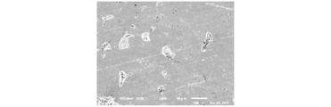
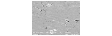
- FIG. 7 is a SEM image (500 times) after finishing honing, which is obtained by simultaneously photographing the inner peripheral surface and the cross section of the cylinder liner, and is a diagram showing an example of Example 2;
- FIG. 6 is an SEM image (500 times) after finishing honing, which is obtained by simultaneously photographing the inner peripheral surface and the cross section of the cylinder liner, and shows an example of Comparative Example 1. It is a laser microscope photograph (1000 times) in a cylinder liner inner peripheral surface, and is a figure which shows the state before image processing which measures the area ratio of a pit.
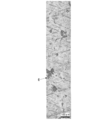
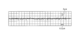
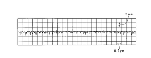
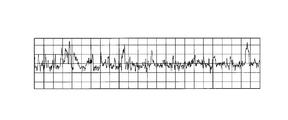
- FIG. 8 is a diagram showing the surface roughness of the inner peripheral surface of the cylinder liner of Example 2 before the nitriding treatment (after the second honing).
- FIG. 6 is a diagram showing the surface roughness of the inner peripheral surface of the cylinder liner of Example 2 after nitriding treatment.
- FIG. 6 is a diagram showing the surface roughness of the inner peripheral surface of the cylinder liner of Example 2 after finishing honing.
- FIG. 8 is a diagram showing an SEM image after nitriding treatment on the inner peripheral surface of the cylinder liner of Example 2;
- FIG. 6 is a diagram showing an SEM image after finishing honing on the inner peripheral surface of the cylinder liner of Example 2;
- FIG. 5 is a diagram showing a surface roughness of a cylinder liner inner peripheral surface of Comparative Example 1 before nitriding treatment (after first honing).
- FIG. 5 is a diagram showing the surface roughness of a cylinder liner inner peripheral surface of Comparative Example 1 after nitriding treatment.
- FIG. 8 is a diagram showing an SEM image after nitriding treatment on the inner peripheral surface of the cylinder liner of Example 2
- FIG. 6 is a diagram showing an SEM image after finishing honing on the inner peripheral surface of the cylinder liner of Example 2
- FIG. 6 is a diagram showing the surface roughness of the inner peripheral surface of the cylinder liner of Comparative Example 1 after finish honing.
- FIG. 6 is a view showing an SEM image of a cylinder liner inner peripheral surface of Comparative Example 1 after nitriding treatment.
- FIG. 6 is a view showing an SEM image after finishing honing on the inner peripheral surface of the cylinder liner of Comparative Example 1. The figure which shows the surface roughness before the nitriding process (after the 2nd honing, but only the 2nd extended grindstone process) in the cylinder liner inner peripheral surface of the comparative example 2.
- FIG. 4 is a diagram showing the surface roughness of a cylinder liner inner peripheral surface of Comparative Example 2 after nitriding treatment.
- FIG. 6 is a diagram showing the surface roughness of the inner peripheral surface of the cylinder liner of Comparative Example 2 after finish honing.
- FIG. 6 is a view showing an SEM image of a cylinder liner inner peripheral surface of Comparative Example 2 after nitriding treatment.
- FIG. 10 is a view showing an SEM image after finishing honing on the inner peripheral surface of the cylinder liner of Comparative Example 2;
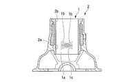
- FIG. 1 shows a partial sectional structure of a cylinder block 2 provided with a cylinder liner 1 according to an embodiment of the present invention.
- the cylinder block 2 is made of cast iron or a light alloy such as an aluminum alloy, and the cylinder liner 1 is made of flake graphite cast iron.
- At least the inner peripheral surface 1a of the cylinder liner 1 is formed with a nitriding layer by gas nitriding treatment, and further, a crosshatch portion 1c including a groove portion 1b is formed by honing processing, and a fitting portion 2a formed on the cylinder block 2 is formed. It is engaged at 2b.
- a cooling water passage is formed between the fitting portions 2a and 2b of the cylinder block 2 on the outer peripheral surface of the cylinder liner 1.
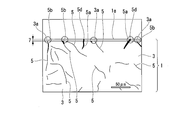
- the flake graphite cast iron forming the cylinder liner 1 is a cast iron base made of an iron-based alloy in a cross section orthogonal to the sliding direction of the piston ring with respect to the inner peripheral surface 1a of the cylinder liner 1 as shown in FIG. 3 has a metallic structure in which a plurality of flaky free graphite 5 are dispersed and crystallized, and a compound layer 7 formed by nitriding treatment is formed on the inner peripheral surface portion.
- a part of the free graphite 5 extends its part 5a until it reaches the inner peripheral surface 1a. It is dispersed so as to be exposed on the peripheral surface 1a.
- a portion of the free graphite 5 exposed on the inner peripheral surface 1a of the portion 5a is an exposed portion 5d.
- the other free graphite 5 existing in the surface portion having a depth of about 20 ⁇ m has a portion 5b extending toward the inner peripheral surface 1a, but the portion 5b closest to the inner peripheral surface 1a is the inner peripheral surface 1a.
- a small distance (a distance of about 10 ⁇ m or less) is dispersed. That is, the other free graphite 5 existing on the surface portion has a portion 5b extending to the vicinity of the inner peripheral surface 1a, but has a coating portion 3a made of the material forming the cast iron matrix 3.
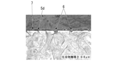
- 3A and 3B show a metallographic structure and a compound layer 7 (white layer on the surface) of a cross section on the inner peripheral side in the cylinder liner after a finishing honing by a 400 ⁇ metallurgical microscope.
- the portion of the free graphite reaching the inner peripheral surface is covered with the material forming the cast iron matrix, and the free graphite is not exposed at the surface portion of the inner peripheral surface.
- FIG. 3B a large amount of free graphite is exposed on the surface portion of the inner peripheral surface. Also, a pit 6 has occurred.
- the thickness of the compound layer 7 (white layer) is 8 to 10 ⁇ m in FIG. 3A and 6 to 8 ⁇ m in FIG. 3B.
- the inner peripheral surface 1a of the cylinder liner 1 is a surface on which a piston ring (not shown) and a piston (not shown) slide back and forth. Accordingly, after the gas nitriding treatment, the fragile porous layer formed by the nitriding treatment existing on the surface portion is removed, and finish honing is performed to form a proper surface as a sliding surface.
- the roughness curve has a plateau honing shape with smooth peaks, and the 10-point average roughness Rz according to JIS B0601:1982 is preferably 4.0 ⁇ m or less.
- the ten-point average roughness Rz is more preferably 1.5 ⁇ m or more and 4.0 ⁇ m or less.
- the inner circumferential surface 1a of the cylinder liner 1 is a pair that forms an angle of about 30° (called a crosshatch angle) in the direction orthogonal to the axial direction of the cylinder liner 1 by finishing honing.
- a cross hatch portion 1c composed of the groove portion 1b is formed.
- the cross hatch angle is not limited to 30°, and any angle can be selected within the range of 3° to 60°.
- a predetermined nitriding layer is provided in the cross section of the inner peripheral surface, which has a proper surface texture as a sliding surface by finish honing.
- the nitriding layer is formed of a nitriding compound layer (compound layer 7) and a nitrogen diffusion layer from the surface side of the cylinder liner inner peripheral surface 1a, and a metal structure having a micro Vickers hardness of 350 HV0.05 or more. It is preferable that the compound layer 7 has a thickness of 3 ⁇ m or more from the inner peripheral surface and the nitrogen diffusion layer has a thickness of 40 ⁇ m or more from the inner peripheral surface.
- the micro Vickers hardness is based on JIS Z 2244:2009 below.
- the thickness of the compound layer 7 is preferably 15 ⁇ m or less from the inner peripheral surface. Beyond this, the opening area of the pit 6 increases and the depth also increases. The thickness of the compound layer 7 is more preferably 3 ⁇ m or more and 12 ⁇ m or less from the inner peripheral surface.
- the compound layer 7 is obtained by embedding a cut piece of a cylinder liner in a resin, polishing it to a mirror finish, and then immersing it in a 2% coral solution of nital etching and observing it with a metal microscope (400 times).
- the compound layer 7 can be confirmed as a white layer as shown in FIGS. 3A and 3B.
- the compound layer 7 preferably has a micro Vickers hardness of 700 HV0.05 or more according to JIS Z 2244:2009.
- the boundary between the compound layer 7 and the nitrogen diffusion layer may be confirmed by the hardness, and the hardness may be Micro Vickers hardness.
- the compound layer 7 has a micro Vickers hardness of about 900 HmV and the nitrogen diffusion layer of the same has a micro Vickers hardness of about 350 HmV according to JIS Z 2244:2009. From this, the boundary between the compound layer 7 and the nitrogen diffusion layer can be confirmed by the difference in hardness between the compound layer 7 and the nitrogen diffusion layer.
- the thickness of the compound layer 7 is the minimum value at four arbitrary points, by making a cut piece from any four points on the inner peripheral surface 1a of each cylinder liner and measuring the thickness range of the compound layer 7 with a metallurgical microscope. To the maximum value.
- each cylinder liner is opposed to two points in the axial direction of the cylinder liner, which are opposed to each other in the radial direction at the central position, and to the radial direction at any position 20 to 50 mm from the end surface of the cylinder liner.
- the two radial directions are orthogonal to each other.
- the thickness of the nitrogen diffusion layer is determined by measuring the hardness of the base material of the cast iron base 3 (about 300 HmV from the boundary between the compound layer 7 and the nitrogen diffusion layer to the cast iron base 3 side in the cut piece used for measuring the thickness of the compound layer 7). ) It may be a range to reach.
- FIG. 4A and FIG. 4B show 500 times SEM images of the inner peripheral surface 1a and the metal structure of the cross section which are simultaneously imaged.
- FIG. 4A the exposure of the free graphite to the inner peripheral surface is small, and in FIG. 4B, the exposure of the free graphite to the inner peripheral surface is large, and the existence of the pits 6 can be confirmed.
- the cylinder liner When finishing cross-hatching is performed on the surface of the nitriding layer by finishing honing the inner surface after nitriding the cylinder liner, the cylinder liner is subjected to nitriding around the exposed portion of the inner surface of the free graphite that is not nitrided. Since the base on the inner peripheral surface is raised and the base forms the hard and brittle compound layer 7, the grinding stone expanding force of the finishing honing is concentrated on the raised base. As a result, the base portion composed of the compound layer 7 is deficient, or graphite is simultaneously dropped off, and the pit 6 is generated. Therefore, the depth of the pit 6 is considered to be equal to or less than the thickness of the compound layer 7.
- the size of the opening of the pit 6 on the inner peripheral surface 1a of the cylinder liner is about 10 to 100 ⁇ m in diameter, as shown in FIGS. 5A, 5B and 5C.
- the area ratio of the pits 6 is preferably 8% or less. It is more preferably 6% or less. The lower the area ratio of the pits 6, the more preferable. However, if the area ratio of the pits 6 is extremely reduced, the risk of seizure increases. Therefore, the area ratio of the pits 6 is preferably 1% or more.
- the free graphite is less exposed to the inner peripheral surface.
- the inner peripheral surface is It was found that when the plastic flow of the cast iron matrix is generated within the range of the thickness where the compound layer 7 of the part is formed, the exposure of the free graphite to the inner peripheral surface can be suppressed. That is, of FIGS. 4A and 4B, FIG. 4A is the state of the preferable inner peripheral surface.
- the graphite open ratio (%) which indicates the ratio of the number of open graphites to the total of the number of open graphites and the number of closed graphites, is determined by determining whether or not the graphite 5b contained in the inner peripheral surface is not exposed (closed graphite).
- the graphite aperture ratio is preferably 50% or less, more preferably 35% or less. If the graphite opening ratio exceeds 50%, the area ratio of the pits 6 becomes large, which is not preferable. The lower the graphite aperture ratio is, the more preferable. However, if the graphite aperture ratio is extremely reduced, the risk of seizure is increased. Therefore, the graphite aperture ratio may be 5% or more.
- FIG. 6 shows an outline of the manufacturing process for the cylinder liner according to the embodiment of the present invention. As shown in FIG. 6, a step of performing a casting step, an outer circumference and an inner circumference turning step, a first honing step, a second honing step (2 steps of grinding stone expansion), a nitriding step, and a finishing honing step can be adopted as an example. ..
- the casting method of the cylinder liner 1 is not particularly limited, and a known casting method such as a sand casting method or a centrifugal casting method can be used.
- the material forming the cylinder liner of the present embodiment is flake graphite cast iron.
- the material forming the cylinder liner is% by mass, C: 2.5% or more and 3.5% or less, Si: 1.7% or more and 2.5% or less, Mn: 0.5% or more and 1.0% or less.
- composition containing 0.4% or less of the above and the balance Fe and unavoidable impurities, and the composition may contain at least one element such as B, Cu, Nb, and W.
- the size of graphite is not particularly limited, but is, for example, 4 to 6 (ISO 945-1:2008), the type of graphite is 70% or more of A type, and it is common in the matrix of flake graphite cast iron.
- the crystalline hardened material phase may be contained in an amount of 5% or less.
- the hardness of the material may be 90 HRB or more and 115 HRB or less according to JIS Z 2245:2011.
- a cylindrical cylinder liner material having a product inner diameter of 80-220 mm and a product length of 80-450 mm is obtained.
- the inner and outer peripheral surfaces of the cylinder liner are roughly ground to remove black skin such as oxide film, and then the inner and outer peripheral surfaces are rough processed.
- the inner peripheral surface and the outer peripheral surface are processed into a state close to the target dimension by an NC lathe or the like, and the finishing processing is completed on the outer peripheral surface.
- the inner peripheral surface is processed by honing using a honing grindstone (first honing step) to an inner diameter close to the finish as a product, and then the inner peripheral surface that is adapted to the properties of the inner peripheral surface after nitriding treatment.
- a precise honing process is performed on the surface (second honing process), followed by a nitriding process and a finishing honing process (finish honing process) to manufacture a product.
- the grindstone is a CBN (Cubic Boron Nitride)-based grindstone with a metal bond bond or a GC (silicon carbide) grindstone with a vitrified bond. In both cases, the particle size is preferably between #200 and #400.
- the honing head a tool for holding the grindstone and expanding the grindstone toward the inner peripheral surface of the cylinder liner
- the first grindstone CBN quality grindstone
- the second grindstone which is a GC quality grindstone, also referred to as the second expanded grindstone
- the surface roughness of the inner peripheral surface the ten-point average roughness Rz according to JIS B6010:1982 is preferably 3.0 ⁇ m or less, and the maximum height Rmax is preferably 3.5 ⁇ m or less.
- the roughness curve preferably has a single honing shape.
- the machining allowance for the first honing process is preferably set to about 100 ⁇ m in diameter.
- the surface roughness conforms to JIS B6010:1982.
- the first grindstone (also referred to as the first extended grindstone) is a diamond grindstone and has a metal bond bond, and the grain size is preferably larger than #700.
- the surface roughness of the inner peripheral surface is such that the ten-point average roughness Rz is 2.5 ⁇ m or less and the maximum height Rmax is 3.0 ⁇ m or less.
- the roughness curve preferably has a single honing shape.
- the second grindstone (also referred to as the second extended grindstone) is a GC quality grindstone and has a metal bond bond, and the grain size is preferably larger than #1000.
- the ten-point average roughness Rz is 1.6 ⁇ m or less and the maximum height Rmax is 2.6 ⁇ m or less.
- the plateau honing shape is preferable for the roughness curve after processing with the second grindstone.
- the surface roughness of the inner peripheral surface is more preferably such that the ten-point average roughness Rz is 0.5 ⁇ m or more and 2.0 ⁇ m or less and the maximum height Rmax is 0.3 ⁇ m or more and 1.5 ⁇ m or less.
- the total machining allowance by the first grindstone machining and the second grindstone machining is set to about 20 ⁇ m in diameter.
- the roughness curve is made into a single honing shape by the first expansion grindstone and the surface roughness is reduced, and then the peak of the roughness curve formed by the first expansion grindstone by the second expansion grindstone.
- a plateau honing is performed to form a roughness curve by the processing for removing the portion, and plastic flow is generated on the outermost surface of the cylinder liner metallographic structure to minimize the graphite exposure on the surface of the inner peripheral surface 1a. Due to this effect, as shown in FIG. 2 or FIG. 3A, a part of the free graphite 5 has a part 5b extending to the vicinity of the inner peripheral surface 1a, but the coating covered with the material forming the cast iron matrix. These parts 5b with parts 3a can be expressed. This realizes a graphite aperture ratio of 50% or less.
- a nitriding process After performing the second honing process, a nitriding process is performed.
- the temperature In the nitriding treatment, in a dedicated nitriding furnace filled with ammonia (NH 3 ) gas as a reaction gas, for example, the temperature is kept at 560° C. to 600° C. for about 30 to 90 minutes, and the furnace is cooled to a constant temperature after heating. It can be carried out.
- NH 3 ammonia
- the metal structure of the inner peripheral surface is such that the compound layer 7 is formed from the surface of the cylinder liner to a thickness of about 4 ⁇ m to about 20 ⁇ m by the nitriding treatment, and the nitrogen diffusion layer is further inward from the surface of the cylinder liner to a depth of about 50 ⁇ m or more. It is formed.
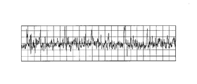
- the inner peripheral surface after the nitriding treatment is, for example, as shown in FIG. 7B, due to the base layer of the inner peripheral surface of the cylinder liner around the exposed portion of the porous layer formed on the outermost surface and the inner peripheral surface of the non-nitrided free graphite.
- the roughness curve of the inner peripheral surface has a shape in which the peaks are high and the valleys are low, and the ten-point average roughness Rz is in the level of 4 ⁇ m to 6 ⁇ m.
- the surface roughness is 4 to 5 times that of the inner peripheral surface.
- Finishing Honing is used to finish the product to the specified inner peripheral surface properties.
- Two kinds of grindstones are attached to the honing head of one honing machine, the first grindstone is a diamond grindstone electrodeposited (Ni plating fixed), the grain size is larger than #700, and the second grindstone is the GC grindstone. It is preferable to use cork bonding, the grain size is larger than #300, and the two types of grindstones are simultaneously expanded.
- the first grindstone has a crosshatch portion on the inner peripheral surface.
- the second grindstone plays a role of forming the roughness curve into a plateau honing shape by the processing for removing the peak portion of the roughness curve by the first grindstone.
- the brittle porous layer formed by the nitriding treatment existing on the surface portion of the inner peripheral surface 1a of the cylinder liner is removed, and the groove portion 1b for ensuring oil retention is formed to form a cross hatch.
- the surface texture of the nitriding layer is formed on the inner peripheral surface 1a of the cylinder liner 1 by finishing the surface roughness in a desired range, for example, the ten-point average roughness Rz to 4.0 ⁇ m or less.
- the area ratio of the pit 6 is controlled to 8% or less.
- the allowance for finishing honing is set to about 1 to 3 ⁇ m.
- cylinder liners of Examples 1 to 4 and Comparative Examples 1 to 3 Seven types of cylinder liners of Examples 1 to 4 and Comparative Examples 1 to 3 were manufactured by the following procedure.
- the honing process was divided into three types, and as shown in Table 1 below, comparative examples and examples were allocated, and five each were prepared.
- Type I Comparative Example 1
- Type II-1 Comparative example 2
- Type II-2 Comparative Example 3 and Examples 1 to 4
- the honing conditions of the first honing process are the same in all the examples and comparative examples.
- Comparative Example 1 proceeds to the nitriding process without passing through the second honing process.
- the second honing process is processed only by the second extended grindstone, and the process proceeds to the nitriding process.
- Comparative Example 3 and Examples 1 to 4 processing was performed with a combination in which the number of strokes of each of the first extended grindstone and the second extended grindstone was changed, and the nitriding process was performed. The above is described in Table 2.
- Table 3 shows the average values of the measured data of the surface roughness of the inner peripheral surface before and after the nitriding treatment, the area ratio of the pits after finishing honing, the graphite aperture ratio, the compound layer thickness, and the surface roughness of the cylinder liner in each example. Indicates.
- the area ratio of the pits was evaluated as follows. Area ratio of pits is 6% or less ⁇ A Area ratio of pit exceeds 6% and 8% or less... B Area ratio of pit exceeds 8% and 10% or less... C The pit area ratio exceeds 10%....D
- the risk of scuffing can be reduced.
Landscapes
- Engineering & Computer Science (AREA)
- Mechanical Engineering (AREA)
- Chemical & Material Sciences (AREA)
- Combustion & Propulsion (AREA)
- General Engineering & Computer Science (AREA)
- Organic Chemistry (AREA)
- Materials Engineering (AREA)
- Metallurgy (AREA)
- Geometry (AREA)
- Physics & Mathematics (AREA)
- Cylinder Crankcases Of Internal Combustion Engines (AREA)
- Pistons, Piston Rings, And Cylinders (AREA)
- Solid-Phase Diffusion Into Metallic Material Surfaces (AREA)
Abstract
Une chemise de cylindre selon la présente invention est caractérisée en ce qu'elle est constituée d'une fonte à graphite lamellaire, fixée à un bloc-cylindres, ayant au moins une couche nitrurée sur la surface périphérique interne de la chemise de cylindre, et ayant une section de trappe transversale formée en son sein, la courbe de rugosité de la surface périphérique interne ayant une forme de rodage plate, la rugosité moyenne sur dix points Rz de la surface périphérique interne selon la norme JIS B0601:1982 n'est pas supérieure à 4,0 µm, et la fraction surfacique des morceaux formée sur la surface périphérique interne a une valeur moyenne non supérieure à 8 %.
Priority Applications (4)
| Application Number | Priority Date | Filing Date | Title |
|---|---|---|---|
| KR1020217019431A KR102367472B1 (ko) | 2018-11-28 | 2019-07-23 | 실린더 라이너 및 그 제조 방법 |
| US17/296,877 US11499498B2 (en) | 2018-11-28 | 2019-07-23 | Cylinder liner and manufacturing method for same |
| EP19889250.7A EP3889414B1 (fr) | 2018-11-28 | 2019-07-23 | Chemise de cylindre et procédé de fabrication correspondant |
| RU2021118035A RU2764951C1 (ru) | 2018-11-28 | 2019-07-23 | Гильза цилиндра и способ ее изготовления |
Applications Claiming Priority (2)
| Application Number | Priority Date | Filing Date | Title |
|---|---|---|---|
| JP2018-222727 | 2018-11-28 | ||
| JP2018222727A JP6553275B1 (ja) | 2018-11-28 | 2018-11-28 | シリンダライナ及びその製造方法 |
Publications (1)
| Publication Number | Publication Date |
|---|---|
| WO2020110366A1 true WO2020110366A1 (fr) | 2020-06-04 |
Family
ID=67473277
Family Applications (1)
| Application Number | Title | Priority Date | Filing Date |
|---|---|---|---|
| PCT/JP2019/028782 Ceased WO2020110366A1 (fr) | 2018-11-28 | 2019-07-23 | Chemise de cylindre et procédé de fabrication correspondant |
Country Status (7)
| Country | Link |
|---|---|
| US (1) | US11499498B2 (fr) |
| EP (1) | EP3889414B1 (fr) |
| JP (1) | JP6553275B1 (fr) |
| KR (1) | KR102367472B1 (fr) |
| CN (2) | CN211082061U (fr) |
| RU (1) | RU2764951C1 (fr) |
| WO (1) | WO2020110366A1 (fr) |
Families Citing this family (1)
| Publication number | Priority date | Publication date | Assignee | Title |
|---|---|---|---|---|
| US12029437B1 (en) | 2020-08-14 | 2024-07-09 | Henry Schein, Inc. | Hand piece for powered osteotome |
Citations (10)
| Publication number | Priority date | Publication date | Assignee | Title |
|---|---|---|---|---|
| JPS6044112B2 (ja) | 1976-05-17 | 1985-10-01 | 株式会社小松製作所 | シリンダライナの内面仕上げ方法 |
| JPS61171964A (ja) * | 1985-01-25 | 1986-08-02 | Mazda Motor Corp | 耐摩耗性に優れた摺接部材 |
| JPH03134252A (ja) * | 1989-10-18 | 1991-06-07 | Izumi Ind Ltd | 内燃機関用アルミニウム合金複合部材 |
| JPH04258572A (ja) * | 1991-02-13 | 1992-09-14 | Hitachi Zosen Corp | 摺動材料 |
| JPH0667836U (ja) * | 1993-03-03 | 1994-09-22 | 日産ディーゼル工業株式会社 | 内燃機関のシリンダライナの構造 |
| JP2000283291A (ja) | 1999-03-31 | 2000-10-13 | Nippon Piston Ring Co Ltd | シリンダライナ |
| JP2002364455A (ja) * | 2001-06-11 | 2002-12-18 | Nissan Motor Co Ltd | シリンダブロックとその成形方法及び装置 |
| JP2008019718A (ja) * | 2006-07-10 | 2008-01-31 | Nissan Motor Co Ltd | 内燃機関 |
| WO2014065156A1 (fr) * | 2012-10-26 | 2014-05-01 | いすゞ自動車株式会社 | Bloc-cylindres et procédé de pierrage |
| JP2016205159A (ja) * | 2015-04-16 | 2016-12-08 | トヨタ自動車株式会社 | シリンダブロックの製造方法 |
Family Cites Families (13)
| Publication number | Priority date | Publication date | Assignee | Title |
|---|---|---|---|---|
| JPS6044112A (ja) | 1983-08-19 | 1985-03-09 | Nippon Steel Corp | 継目なし鋼管穿孔設備におけるプラグバ−cフツク装置 |
| DE3601319A1 (de) | 1985-01-18 | 1986-07-24 | Mazda Motor Corp., Hiroshima | Verfahren zum ausbilden einer abriebfesten gleitflaeche |
| EP0424109A3 (en) * | 1989-10-18 | 1991-10-02 | Izumi Industries Ltd. | Aluminium alloy matrix composite for internal combustion engines |
| JPH0667836A (ja) | 1992-08-20 | 1994-03-11 | Sharp Corp | 指定エリア掲示機能を有する表示装置 |
| CN1176300C (zh) | 2002-08-14 | 2004-11-17 | 扬州五亭桥缸套有限公司 | 一种铸铁氮化平台网纹气缸套 |
| RU2252854C1 (ru) * | 2004-02-09 | 2005-05-27 | Орловский государственный технический университет (ОрелГТУ) | Комбинированный способ шлифохонингования |
| JP5229743B2 (ja) | 2007-06-26 | 2013-07-03 | 国立大学法人岩手大学 | 片状黒鉛鋳鉄およびその製造方法 |
| CN201461116U (zh) | 2009-07-01 | 2010-05-12 | 河南省中原内配股份有限公司 | 一种立式发动机平台珩磨网纹气缸套 |
| RU2482951C1 (ru) * | 2011-09-13 | 2013-05-27 | Открытое акционерное общество "Акционерная Компания "Туламашзавод" | Способ финишной обработки полости гильзы цилиндра двс и устройства для его осуществления |
| CN103667861B (zh) | 2012-08-30 | 2016-10-05 | 日本活塞环株式会社 | 气缸套 |
| CN106555697A (zh) | 2015-09-29 | 2017-04-05 | 张凌 | 石墨铸铁气缸套 |
| BR112017008486B1 (pt) | 2016-09-05 | 2021-06-15 | Tpr Co., Ltd. | Elemento cilíndrico feito de ferro fundido de grafite em floco |
| CN108747798B (zh) | 2018-05-29 | 2023-09-12 | 中原内配集团股份有限公司 | 一种差异化珩磨气缸套及其制备方法 |
-
2018
- 2018-11-28 JP JP2018222727A patent/JP6553275B1/ja active Active
-
2019
- 2019-07-23 US US17/296,877 patent/US11499498B2/en active Active
- 2019-07-23 EP EP19889250.7A patent/EP3889414B1/fr active Active
- 2019-07-23 RU RU2021118035A patent/RU2764951C1/ru active
- 2019-07-23 KR KR1020217019431A patent/KR102367472B1/ko active Active
- 2019-07-23 WO PCT/JP2019/028782 patent/WO2020110366A1/fr not_active Ceased
- 2019-11-21 CN CN201922033993.3U patent/CN211082061U/zh active Active
- 2019-11-21 CN CN201911145749.4A patent/CN111173636B/zh active Active
Patent Citations (10)
| Publication number | Priority date | Publication date | Assignee | Title |
|---|---|---|---|---|
| JPS6044112B2 (ja) | 1976-05-17 | 1985-10-01 | 株式会社小松製作所 | シリンダライナの内面仕上げ方法 |
| JPS61171964A (ja) * | 1985-01-25 | 1986-08-02 | Mazda Motor Corp | 耐摩耗性に優れた摺接部材 |
| JPH03134252A (ja) * | 1989-10-18 | 1991-06-07 | Izumi Ind Ltd | 内燃機関用アルミニウム合金複合部材 |
| JPH04258572A (ja) * | 1991-02-13 | 1992-09-14 | Hitachi Zosen Corp | 摺動材料 |
| JPH0667836U (ja) * | 1993-03-03 | 1994-09-22 | 日産ディーゼル工業株式会社 | 内燃機関のシリンダライナの構造 |
| JP2000283291A (ja) | 1999-03-31 | 2000-10-13 | Nippon Piston Ring Co Ltd | シリンダライナ |
| JP2002364455A (ja) * | 2001-06-11 | 2002-12-18 | Nissan Motor Co Ltd | シリンダブロックとその成形方法及び装置 |
| JP2008019718A (ja) * | 2006-07-10 | 2008-01-31 | Nissan Motor Co Ltd | 内燃機関 |
| WO2014065156A1 (fr) * | 2012-10-26 | 2014-05-01 | いすゞ自動車株式会社 | Bloc-cylindres et procédé de pierrage |
| JP2016205159A (ja) * | 2015-04-16 | 2016-12-08 | トヨタ自動車株式会社 | シリンダブロックの製造方法 |
Non-Patent Citations (1)
| Title |
|---|
| See also references of EP3889414A4 |
Also Published As
| Publication number | Publication date |
|---|---|
| CN211082061U (zh) | 2020-07-24 |
| JP2020084916A (ja) | 2020-06-04 |
| EP3889414A4 (fr) | 2022-08-24 |
| US20220025829A1 (en) | 2022-01-27 |
| EP3889414A1 (fr) | 2021-10-06 |
| EP3889414B1 (fr) | 2024-09-04 |
| RU2764951C1 (ru) | 2022-01-24 |
| JP6553275B1 (ja) | 2019-07-31 |
| US11499498B2 (en) | 2022-11-15 |
| CN111173636B (zh) | 2021-06-04 |
| CN111173636A (zh) | 2020-05-19 |
| KR20210094025A (ko) | 2021-07-28 |
| KR102367472B1 (ko) | 2022-02-24 |
Similar Documents
| Publication | Publication Date | Title |
|---|---|---|
| EP3657000B2 (fr) | Chemise de cylindre en fonte, et moteur à combustion interne | |
| US7059290B2 (en) | Cylinder liner with its inner peripheral surface formed with surface treatment layer, and method for machining to the surface treatment layer | |
| JP4954644B2 (ja) | シリンダライナとピストンリングの組み合わせ | |
| JP5903085B2 (ja) | シリンダボアとピストンリングの組合せ | |
| JP2003013163A (ja) | 粉末アルミニウム合金製摺動部材及びシリンダとピストンリングの組み合わせ | |
| EP3315624B1 (fr) | Élément cylindrique en fonte de graphite lamellaire | |
| JP4557731B2 (ja) | 耐食性と耐摩耗性に優れた鋳鉄 | |
| WO2020095807A1 (fr) | Segment de piston | |
| WO2020110366A1 (fr) | Chemise de cylindre et procédé de fabrication correspondant | |
| JP7488491B2 (ja) | クランクシャフト及びその製造方法 | |
| JPH11153059A (ja) | シリンダライナ及びその製造方法 | |
| JP2007285312A (ja) | 摺動部材 | |
| JP2007270880A (ja) | ピストンリング | |
| JP7435803B2 (ja) | 溶射被膜及び該溶射被膜の製造方法 | |
| JPH0432549A (ja) | 鋳鉄材の耐摩耗性窒化層とその製造方法 |
Legal Events
| Date | Code | Title | Description |
|---|---|---|---|
| 121 | Ep: the epo has been informed by wipo that ep was designated in this application |
Ref document number: 19889250 Country of ref document: EP Kind code of ref document: A1 |
|
| NENP | Non-entry into the national phase |
Ref country code: DE |
|
| ENP | Entry into the national phase |
Ref document number: 20217019431 Country of ref document: KR Kind code of ref document: A |
|
| ENP | Entry into the national phase |
Ref document number: 2019889250 Country of ref document: EP Effective date: 20210628 |