WO2020121552A1 - Dispositif de désulfuration des gaz de combustion - Google Patents
Dispositif de désulfuration des gaz de combustion Download PDFInfo
- Publication number
- WO2020121552A1 WO2020121552A1 PCT/JP2019/020478 JP2019020478W WO2020121552A1 WO 2020121552 A1 WO2020121552 A1 WO 2020121552A1 JP 2019020478 W JP2019020478 W JP 2019020478W WO 2020121552 A1 WO2020121552 A1 WO 2020121552A1
- Authority
- WO
- WIPO (PCT)
- Prior art keywords
- injection nozzle
- side wall
- cleaning liquid
- exhaust gas
- liquid
- Prior art date
- Legal status (The legal status is an assumption and is not a legal conclusion. Google has not performed a legal analysis and makes no representation as to the accuracy of the status listed.)
- Ceased
Links
Images


Classifications
-
- B—PERFORMING OPERATIONS; TRANSPORTING
- B01—PHYSICAL OR CHEMICAL PROCESSES OR APPARATUS IN GENERAL
- B01D—SEPARATION
- B01D53/00—Separation of gases or vapours; Recovering vapours of volatile solvents from gases; Chemical or biological purification of waste gases, e.g. engine exhaust gases, smoke, fumes, flue gases, aerosols
- B01D53/14—Separation of gases or vapours; Recovering vapours of volatile solvents from gases; Chemical or biological purification of waste gases, e.g. engine exhaust gases, smoke, fumes, flue gases, aerosols by absorption
- B01D53/1456—Removing acid components
- B01D53/1481—Removing sulfur dioxide or sulfur trioxide
-
- B—PERFORMING OPERATIONS; TRANSPORTING
- B01—PHYSICAL OR CHEMICAL PROCESSES OR APPARATUS IN GENERAL
- B01D—SEPARATION
- B01D53/00—Separation of gases or vapours; Recovering vapours of volatile solvents from gases; Chemical or biological purification of waste gases, e.g. engine exhaust gases, smoke, fumes, flue gases, aerosols
- B01D53/34—Chemical or biological purification of waste gases
- B01D53/46—Removing components of defined structure
- B01D53/48—Sulfur compounds
- B01D53/50—Sulfur oxides
- B01D53/501—Sulfur oxides by treating the gases with a solution or a suspension of an alkali or earth-alkali or ammonium compound
- B01D53/504—Sulfur oxides by treating the gases with a solution or a suspension of an alkali or earth-alkali or ammonium compound characterised by a specific device
-
- B—PERFORMING OPERATIONS; TRANSPORTING
- B01—PHYSICAL OR CHEMICAL PROCESSES OR APPARATUS IN GENERAL
- B01D—SEPARATION
- B01D47/00—Separating dispersed particles from gases, air or vapours by liquid as separating agent
- B01D47/06—Spray cleaning
- B01D47/063—Spray cleaning with two or more jets impinging against each other
-
- B—PERFORMING OPERATIONS; TRANSPORTING
- B01—PHYSICAL OR CHEMICAL PROCESSES OR APPARATUS IN GENERAL
- B01D—SEPARATION
- B01D53/00—Separation of gases or vapours; Recovering vapours of volatile solvents from gases; Chemical or biological purification of waste gases, e.g. engine exhaust gases, smoke, fumes, flue gases, aerosols
- B01D53/14—Separation of gases or vapours; Recovering vapours of volatile solvents from gases; Chemical or biological purification of waste gases, e.g. engine exhaust gases, smoke, fumes, flue gases, aerosols by absorption
- B01D53/18—Absorbing units; Liquid distributors therefor
- B01D53/185—Liquid distributors
-
- B—PERFORMING OPERATIONS; TRANSPORTING
- B01—PHYSICAL OR CHEMICAL PROCESSES OR APPARATUS IN GENERAL
- B01D—SEPARATION
- B01D53/00—Separation of gases or vapours; Recovering vapours of volatile solvents from gases; Chemical or biological purification of waste gases, e.g. engine exhaust gases, smoke, fumes, flue gases, aerosols
- B01D53/34—Chemical or biological purification of waste gases
- B01D53/46—Removing components of defined structure
- B01D53/48—Sulfur compounds
- B01D53/50—Sulfur oxides
-
- B—PERFORMING OPERATIONS; TRANSPORTING
- B01—PHYSICAL OR CHEMICAL PROCESSES OR APPARATUS IN GENERAL
- B01D—SEPARATION
- B01D53/00—Separation of gases or vapours; Recovering vapours of volatile solvents from gases; Chemical or biological purification of waste gases, e.g. engine exhaust gases, smoke, fumes, flue gases, aerosols
- B01D53/34—Chemical or biological purification of waste gases
- B01D53/74—General processes for purification of waste gases; Apparatus or devices specially adapted therefor
- B01D53/77—Liquid phase processes
- B01D53/78—Liquid phase processes with gas-liquid contact
-
- B—PERFORMING OPERATIONS; TRANSPORTING
- B01—PHYSICAL OR CHEMICAL PROCESSES OR APPARATUS IN GENERAL
- B01F—MIXING, e.g. DISSOLVING, EMULSIFYING OR DISPERSING
- B01F23/00—Mixing according to the phases to be mixed, e.g. dispersing or emulsifying
- B01F23/20—Mixing gases with liquids
-
- B—PERFORMING OPERATIONS; TRANSPORTING
- B01—PHYSICAL OR CHEMICAL PROCESSES OR APPARATUS IN GENERAL
- B01F—MIXING, e.g. DISSOLVING, EMULSIFYING OR DISPERSING
- B01F23/00—Mixing according to the phases to be mixed, e.g. dispersing or emulsifying
- B01F23/20—Mixing gases with liquids
- B01F23/21—Mixing gases with liquids by introducing liquids into gaseous media
- B01F23/213—Mixing gases with liquids by introducing liquids into gaseous media by spraying or atomising of the liquids
- B01F23/2132—Mixing gases with liquids by introducing liquids into gaseous media by spraying or atomising of the liquids using nozzles
- B01F23/21321—High pressure atomization, i.e. the liquid is atomized and sprayed by a jet at high pressure
-
- B—PERFORMING OPERATIONS; TRANSPORTING
- B01—PHYSICAL OR CHEMICAL PROCESSES OR APPARATUS IN GENERAL
- B01F—MIXING, e.g. DISSOLVING, EMULSIFYING OR DISPERSING
- B01F23/00—Mixing according to the phases to be mixed, e.g. dispersing or emulsifying
- B01F23/20—Mixing gases with liquids
- B01F23/23—Mixing gases with liquids by introducing gases into liquid media, e.g. for producing aerated liquids
- B01F23/232—Mixing gases with liquids by introducing gases into liquid media, e.g. for producing aerated liquids using flow-mixing means for introducing the gases, e.g. baffles
- B01F23/2323—Mixing gases with liquids by introducing gases into liquid media, e.g. for producing aerated liquids using flow-mixing means for introducing the gases, e.g. baffles by circulating the flow in guiding constructions or conduits
-
- B—PERFORMING OPERATIONS; TRANSPORTING
- B01—PHYSICAL OR CHEMICAL PROCESSES OR APPARATUS IN GENERAL
- B01F—MIXING, e.g. DISSOLVING, EMULSIFYING OR DISPERSING
- B01F23/00—Mixing according to the phases to be mixed, e.g. dispersing or emulsifying
- B01F23/40—Mixing liquids with liquids; Emulsifying
- B01F23/45—Mixing liquids with liquids; Emulsifying using flow mixing
- B01F23/454—Mixing liquids with liquids; Emulsifying using flow mixing by injecting a mixture of liquid and gas
-
- B—PERFORMING OPERATIONS; TRANSPORTING
- B01—PHYSICAL OR CHEMICAL PROCESSES OR APPARATUS IN GENERAL
- B01F—MIXING, e.g. DISSOLVING, EMULSIFYING OR DISPERSING
- B01F25/00—Flow mixers; Mixers for falling materials, e.g. solid particles
- B01F25/20—Jet mixers, i.e. mixers using high-speed fluid streams
-
- B—PERFORMING OPERATIONS; TRANSPORTING
- B01—PHYSICAL OR CHEMICAL PROCESSES OR APPARATUS IN GENERAL
- B01F—MIXING, e.g. DISSOLVING, EMULSIFYING OR DISPERSING
- B01F25/00—Flow mixers; Mixers for falling materials, e.g. solid particles
- B01F25/30—Injector mixers
- B01F25/31—Injector mixers in conduits or tubes through which the main component flows
- B01F25/312—Injector mixers in conduits or tubes through which the main component flows with Venturi elements; Details thereof
- B01F25/3124—Injector mixers in conduits or tubes through which the main component flows with Venturi elements; Details thereof characterised by the place of introduction of the main flow
- B01F25/31242—Injector mixers in conduits or tubes through which the main component flows with Venturi elements; Details thereof characterised by the place of introduction of the main flow the main flow being injected in the central area of the venturi, creating an aspiration in the circumferential part of the conduit
-
- B—PERFORMING OPERATIONS; TRANSPORTING
- B01—PHYSICAL OR CHEMICAL PROCESSES OR APPARATUS IN GENERAL
- B01F—MIXING, e.g. DISSOLVING, EMULSIFYING OR DISPERSING
- B01F25/00—Flow mixers; Mixers for falling materials, e.g. solid particles
- B01F25/30—Injector mixers
- B01F25/31—Injector mixers in conduits or tubes through which the main component flows
- B01F25/313—Injector mixers in conduits or tubes through which the main component flows wherein additional components are introduced in the centre of the conduit
- B01F25/3132—Injector mixers in conduits or tubes through which the main component flows wherein additional components are introduced in the centre of the conduit by using two or more injector devices
- B01F25/31322—Injector mixers in conduits or tubes through which the main component flows wherein additional components are introduced in the centre of the conduit by using two or more injector devices used simultaneously
-
- B—PERFORMING OPERATIONS; TRANSPORTING
- B01—PHYSICAL OR CHEMICAL PROCESSES OR APPARATUS IN GENERAL
- B01F—MIXING, e.g. DISSOLVING, EMULSIFYING OR DISPERSING
- B01F25/00—Flow mixers; Mixers for falling materials, e.g. solid particles
- B01F25/50—Circulation mixers, e.g. wherein at least part of the mixture is discharged from and reintroduced into a receptacle
- B01F25/53—Circulation mixers, e.g. wherein at least part of the mixture is discharged from and reintroduced into a receptacle in which the mixture is discharged from and reintroduced into a receptacle through a recirculation tube, into which an additional component is introduced
-
- B—PERFORMING OPERATIONS; TRANSPORTING
- B01—PHYSICAL OR CHEMICAL PROCESSES OR APPARATUS IN GENERAL
- B01D—SEPARATION
- B01D2251/00—Reactants
- B01D2251/10—Oxidants
- B01D2251/102—Oxygen
-
- B—PERFORMING OPERATIONS; TRANSPORTING
- B01—PHYSICAL OR CHEMICAL PROCESSES OR APPARATUS IN GENERAL
- B01D—SEPARATION
- B01D2251/00—Reactants
- B01D2251/30—Alkali metal compounds
- B01D2251/304—Alkali metal compounds of sodium
-
- B—PERFORMING OPERATIONS; TRANSPORTING
- B01—PHYSICAL OR CHEMICAL PROCESSES OR APPARATUS IN GENERAL
- B01D—SEPARATION
- B01D2251/00—Reactants
- B01D2251/40—Alkaline earth metal or magnesium compounds
- B01D2251/404—Alkaline earth metal or magnesium compounds of calcium
-
- B—PERFORMING OPERATIONS; TRANSPORTING
- B01—PHYSICAL OR CHEMICAL PROCESSES OR APPARATUS IN GENERAL
- B01D—SEPARATION
- B01D2258/00—Sources of waste gases
- B01D2258/02—Other waste gases
- B01D2258/0283—Flue gases
Definitions
- the present disclosure relates to an exhaust gas desulfurization device for desulfurizing exhaust gas discharged from a combustion device.
- exhaust gas emitted from a combustion engine such as a boiler contains atmospheric pollutants such as SO x (sulfur oxide).
- SO x sulfur oxide
- As a method for reducing SO x contained in the exhaust gas there is a wet desulfurization method in which SO 2 or the like is absorbed and removed by an absorbing solution such as an alkaline aqueous solution or an absorbent slurry.
- the cleaning liquid stored in the liquid pool contains reaction products such as sulfite generated by SO 2 absorbed from the exhaust gas, the cleaning liquid stored in the liquid pool needs to be removed in order to remove the reaction product. Oxidizing a gas containing oxygen such as air may oxidize a reaction product.
- Patent Document 1 discloses a gas-liquid mixing device including an injection nozzle configured to inject a mixed fluid of a gas containing oxygen and a cleaning liquid from a discharge port into a liquid pool.
- the injection nozzle is provided with a throttle part in the middle of the flow path of the cleaning liquid, and the negative pressure region is generated by contracting the cleaning liquid flowing in the flow path by the contraction part. Due to the suction force generated in the negative pressure region, the gas supplied via the branch pipe to the downstream side of the throttle portion of the flow path is sucked. Further, the injection nozzle shears and atomizes the gas sucked by the cleaning liquid flowing through the cleaning liquid flow path to generate a mixed fluid (cleaning liquid containing fine bubbles) and eject the mixed fluid from the discharge port. Is becoming
- the mixed fluid jetted from the jet nozzle flows along the direction of the jet nozzle until it reaches a predetermined jet flow reaching distance.
- the mixed fluid that has reached the predetermined jet arrival distance loses its momentum in the horizontal direction and flows vertically upward due to the buoyancy of the bubbles.
- the mixed fluid jetted from the jet nozzle collides with the bottom surface of the liquid pool and loses the momentum in the horizontal direction, so before reaching the predetermined jet reach distance.
- the mixed fluid will flow vertically upward.
- the oxidation effective volume which is the volume in which the oxidation reaction is promoted by the mixed fluid in the liquid pool, may be smaller than the oxidation effective volume that the mixed fluid injected from the injection nozzle can originally exhibit.
- the effective oxidation volume is small, the oxidation by the mixed fluid becomes insufficient, and there is a risk that many reaction products will remain unoxidized in the cleaning liquid stored in the liquid pool.
- the ejection nozzle in order to sufficiently perform the oxidation by the mixed fluid ejected from the ejection nozzle, it is necessary to find an appropriate direction of the ejection nozzle and arrange the ejection nozzle so as to be in the appropriate direction.
- the injection nozzle is tilted downward and is arranged so as to face the predetermined direction, the axis of the injection nozzle is finely adjusted in the angle between the vertical plane and the horizontal plane when it is attached to the absorption tower. In the above, it is necessary to fix the absorber to the absorption tower, and the installation work time becomes longer accordingly.
- Patent Document 1 discloses a diagram in which the injection nozzles are arranged so as to be inclined downward, but there is no description regarding a specific method or mounting structure for mounting the injection nozzles on the absorption tower. Further, the specification of Patent Document 1 does not specifically mention the installation angle of the injection nozzle.
- an object of at least one embodiment of the present invention is to prevent the effective oxidation volume, which is the volume in which the oxidation reaction is promoted by the mixed fluid injected from the injection nozzle, from decreasing.
- An object of the present invention is to provide an exhaust gas desulfurization device that can easily perform the work when the nozzle is attached to the absorption tower by inclining it at a predetermined angle from the horizontal plane.
- An exhaust gas desulfurization apparatus An exhaust gas desulfurization device for desulfurizing exhaust gas discharged from a combustion device, An absorption tower configured to bring a cleaning liquid into gas-liquid contact with the exhaust gas introduced therein, wherein at least a part is defined by a first side wall of the absorption tower and a second side wall facing the first side wall.
- An absorption tower that internally contains a liquid pool in which the cleaning liquid is stored, A first injection nozzle, the tip of which is inserted into an insertion hole formed in the first side wall, and a mixed fluid of a gas containing oxygen and the cleaning liquid from a first discharge port which is a discharge port of the first injection nozzle.
- a gas-liquid mixing device including a first injection nozzle configured to inject the liquid into the liquid pool,
- the first injection nozzle is A tubular portion that extends along the central axis of the first discharge port and in which the first discharge port is formed;
- a first fastening portion provided so as to project from an outer periphery of the tubular portion along a direction orthogonal to the central axis of the first discharge port,
- the absorption tower is When the inclination angle of the central axis of the first discharge port from the horizontal plane is ⁇ , the outside of the peripheral edge portion of the insertion hole formed in the first side wall along the direction inclined by the angle ⁇ from the horizontal plane.
- a cylindrical protruding portion provided so as to protrude to A second fastening that is provided so as to project from the tip of the tubular projection along a direction orthogonal to the extending direction of the tubular projection and is fixed to the first fastening portion by a fastening device. And a section.
- the first injection nozzle is configured such that the first fastening portion is in a state in which the tip including the first discharge port of the tubular portion is inserted into the insertion hole formed in the first sidewall of the absorption tower.
- the tubular portion extends along the central axis of the first ejection port.
- the cylindrical protrusion of the absorption tower extends along the direction inclined from the horizontal plane by the same angle as the inclination angle ⁇ of the central axis of the first outlet from the horizontal plane. That is, the cylindrical protrusion of the absorption tower extends along the same direction as the central axis of the first discharge port when the first injection nozzle is installed.
- the first injection nozzle extends along a direction orthogonal to the extending direction of the tubular portion and a first fastening portion extending along a direction orthogonal to the extending direction of the tubular protruding portion.
- the inclination angle ⁇ of the first injection nozzle is 10° or less, the gas (bubbles) contained in the mixed fluid injected from the first injection nozzle is washed from the liquid pool to the cleaning liquid. It has been found that there is a greater risk of being caught in the pump for discharging. Further, when the inclination angle ⁇ of the first injection nozzle is 30° or more, the mixed fluid injected from the first injection nozzle collides with the bottom surface of the liquid pool at an early stage, and thus the reaching distance of the mixed fluid becomes short. It was found that the effective oxidation volume, which is the volume in which the oxidation reaction is accelerated by the mixed fluid injected from the first injection nozzle, decreases.
- the first injection nozzle satisfies the condition that the inclination angle ⁇ is 10° ⁇ 30°, and therefore the effective oxidation volume is smaller than the original effective oxidation volume. It is possible to prevent the deterioration of the performance of the pump due to the inclusion of gas (bubbles) in the pump for discharging the cleaning liquid from the liquid reservoir.
- the absorption tower is along a direction in which the first side wall and the second side wall are separated from each other.
- a third side wall that extends in the direction of the first side wall and a second side wall that face the third side wall, the third side wall defining a part of the liquid reservoir, and the first side wall and the second side wall.
- a fourth side wall defining a part of the liquid reservoir, and the gas-liquid mixing device has a second injection nozzle whose tip is inserted into an insertion hole formed in the third side wall.
- a second injection nozzle configured to inject the mixed fluid from the second ejection port, which is the ejection port of the second ejection nozzle, into the liquid pool, and an insertion formed in the fourth sidewall.
- a third jet nozzle the tip of which is inserted into the hole, wherein the third jet nozzle is configured to jet the mixed fluid from the third jet port, which is the jet port of the third jet nozzle, to the liquid reservoir. And, are further included.
- the tip is inserted into the second injection nozzle whose tip is inserted into the insertion hole formed in the third side wall and the insertion hole formed in the fourth side wall.
- a third injection nozzle that is operated. Therefore, for the region in the liquid pool where the oxidation reaction cannot be accelerated by the mixed fluid injected from the first injection nozzle, the oxidation reaction is accelerated by the mixed fluid injected from each of the second injection nozzle and the third injection nozzle. You can Therefore, according to the above configuration, it is possible to reduce a region in the liquid pool where the oxidation reaction cannot be promoted by the mixed fluid, and thus it is possible to prevent insufficient oxidation by the mixed fluid.
- each of the second injection nozzle and the third injection nozzle is arranged at a height position different from that of the first injection nozzle. To be done.
- Each of the second jet nozzle and the third jet nozzle is configured to jet the mixed fluid along a direction intersecting the direction in which the first jet nozzle jets the mixed fluid in a top view. If each of the second jet nozzle and the third jet nozzle is arranged at the same height position as the first jet nozzle, the mixed fluid jetted from each of the second jet nozzle and the third jet nozzle becomes the first jet nozzle. There is a risk of obstructing the flow of the mixed fluid ejected from the ejection nozzle. According to the configuration of (4) above, each of the second jet nozzle and the third jet nozzle is arranged at a height position different from that of the first jet nozzle, so that each of the second jet nozzle and the third jet nozzle is arranged.
- each of the second injection nozzle and the third injection nozzle is separated from the first side wall by a predetermined distance or more. Are placed in the same position.
- each of the second injection nozzle and the third injection nozzle is arranged at a position separated from the first side wall by a predetermined distance or more, so that each of the second injection nozzle and the third injection nozzle is arranged. It is possible to prevent the mixed fluid jetted from the nozzle from blocking the flow of the mixed fluid jetted from the first jet nozzle. Further, by preventing the flow of the mixed fluid injected from the first injection nozzle from being obstructed, the effective oxidation volume, which is the volume in which the oxidation reaction is promoted by the mixed fluid injected from the first injection nozzle, becomes small. Can be prevented.
- each of the second injection nozzle and the third injection nozzle has a predetermined distance from the second side wall. It is placed at a position more than a distance away.
- each of the second injection nozzle and the third injection nozzle is arranged at a position separated from the second side wall by a predetermined distance or more. Therefore, each of the second injection nozzle and the third injection nozzle is It is possible to prevent the mixed fluid jetted from from reaching the cleaning liquid outlet of the second side wall. Therefore, according to the above configuration, it is possible to prevent the performance of the pump from being lowered due to the gas (bubbles) being caught in the pump for discharging the cleaning liquid from the liquid reservoir.
- the ejection nozzle in order to prevent the effective oxidation volume, which is the volume in which the oxidation reaction is promoted by the mixed fluid ejected from the ejection nozzle, from decreasing, the ejection nozzle may be moved to a predetermined plane from the horizontal plane.
- an exhaust gas desulfurization apparatus which can easily perform the work when it is attached to an absorption tower with an angle.
- expressions such as “identical”, “equal”, and “homogeneous” that indicate that they are in the same state are not limited to a state in which they are exactly equal to each other. It also represents the existing state.
- the representation of a shape such as a quadrangle or a cylinder does not only represent a shape such as a quadrangle or a cylinder in a geometrically strict sense, but also an uneven portion or a chamfer within a range in which the same effect can be obtained.
- the shape including parts and the like is also shown.
- the expressions “comprising”, “comprising”, “comprising”, “including”, or “having” one element are not exclusive expressions excluding the existence of other elements. Note that the same configurations are denoted by the same reference numerals, and description thereof may be omitted.
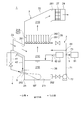
- FIG. 1 is a sectional view showing a schematic configuration of an exhaust gas desulfurization apparatus according to one embodiment.
- the exhaust gas desulfurization device is a device for desulfurizing exhaust gas discharged from the combustion device.
- the combustion device include a diesel engine, a gas turbine engine or a steam turbine engine, a boiler, and the like.
- the exhaust gas desulfurization device 1 includes an absorption tower 2 and a gas-liquid mixing device 4.
- the absorption tower 2 is configured to bring the cleaning liquid into gas-liquid contact with the exhaust gas introduced therein.
- the absorption tower 2 as shown in FIG. 1, is configured to spray the cleaning liquid onto the exhaust gas introduced therein, thereby forming a gas-liquid contact between the exhaust gas and the cleaning liquid.
- the contact portion 21A and the liquid pool portion 21B located below the gas-liquid contact portion and storing the cleaning liquid that has absorbed SO x in the exhaust gas at the gas-liquid contact portion 21A are configured to be defined therein. ..
- examples of the cleaning liquid include a liquid containing an alkaline agent and seawater.
- examples of the alkaline agent include CaCO 3 , NaOH, Ca(OH) 2 , NaHCO 3 , and Na 2 CO 3, and it is also possible to use alkali reduced in volume to a high concentration.
- the absorption tower 2 includes an absorption tower main body portion 22 that internally defines an internal space 21 including the gas-liquid contact portion 21A and the liquid pool portion 21B described above, and an absorption tower main body portion 22.
- An exhaust gas introducing unit 23 for introducing exhaust gas into the tower main body 22 and an exhaust gas discharging unit 24 for exhausting exhaust gas from the absorption tower main body 22 are provided.
- a direction in which the absorption tower main body 22 and the exhaust gas introducing portion 23 are adjacent to each other is a first direction
- an exhaust gas introducing portion 23 side in the first direction is one side
- an exhaust gas discharging portion 24 side in the first direction Is defined as the other side.
- the exhaust gas inlet 251 communicating with the internal space 21 (lower internal space 21C) is formed in the first side wall 25 which is the one side wall in the first direction of the absorption tower body 22.
- the second side wall 26, which is the other side wall in the first direction of the absorption tower body 22, has an exhaust gas outlet communicating with the internal space 21 (upper internal space 21D) at a position higher than the exhaust gas inlet 251. 261 is formed.
- Each of the first side wall 25 and the second side wall 26 extends along a second direction orthogonal to the first direction in a top view and defines at least a part of the internal space 21 including the liquid reservoir 21B. There is.
- Exhaust gas introduced from the combustion device (not shown) into the exhaust gas introducing portion 23 is introduced into the internal space 21 (lower internal space 21C) via the exhaust gas introducing port 251 after passing through the exhaust gas introducing portion 23.
- the exhaust gas introduced into the internal space 21 flows in the lower internal space 21C from the first side wall 25 located on one side toward the second side wall 26 located on the other side, and then flows while rising in the internal space 21. To go.
- the exhaust gas that has risen to the upper internal space 21D flows from the first side wall 25 toward the second side wall 26, and then is discharged to the exhaust gas discharge portion 24 via the exhaust gas discharge port 261.
- the gas-liquid contact portion 21A located above the lower internal space 21C of the absorption tower body 22 and below the upper internal space 21D has the internal space 21 described above.
- a spraying device 28 for spraying the cleaning liquid is arranged.
- the spraying device 28 sprays the cleaning liquid onto the exhaust gas passing through the gas-liquid contact portion 21A and brings the cleaning liquid into gas-liquid contact with each other to absorb and remove SO x (including SO 2 ) contained in the exhaust gas.
- SO x including SO 2
- the spraying device 28 includes a water spray pipe 281 extending along the first direction in the internal space 21 of the absorption tower body 22, and a plurality of water spray nozzles 282 provided in the water spray pipe 281. And, including.
- the water spray nozzle 282 is configured to spray the cleaning liquid toward the downstream side in the flow direction of the exhaust gas, that is, toward the upper side in the vertical direction.
- the sprinkler nozzle 282 is adapted to eject the cleaning liquid in a liquid column shape. That is, the illustrated absorption tower 2 is a liquid column type absorption tower.
- the absorption tower 2 is not limited to the liquid column type described above as long as it is configured to bring the cleaning liquid into gas-liquid contact with the exhaust gas introduced therein.
- the absorption tower 2 is a grid-type absorption tower that includes a packed bed that is filled with a filling material that promotes gas-liquid contact in the internal space 21, or a spray-type absorption tower that includes a water spray nozzle 282 that radially sprays the cleaning liquid. It may be an absorption tower or the like.
- the water sprinkler 281 may extend along a direction orthogonal to the first direction in a top view. Further, the water spray nozzle 282 may be configured to spray the cleaning liquid downward in the vertical direction.
- Exhaust gas that has passed through the gas-liquid contact portion 21A contains a large amount of water.
- a mist eliminator 27 is arranged downstream of the gas-liquid contact portion 21A in the flow direction of the exhaust gas.
- the mist eliminator 27 is configured to remove water from the exhaust gas passing through the mist eliminator 27.
- the exhaust gas that has passed through the mist eliminator 27 is discharged to the outside of the absorption tower 2.
- the mist eliminator 27 is arranged in the exhaust gas discharge part 24 and extends along the vertical direction so as to separate the upstream side and the downstream side in the exhaust gas flow direction in the exhaust gas discharge part 24. There is. Note that the mist eliminator 27 may be arranged in the upper internal space 21D and extend along the horizontal direction. Further, the mist eliminator 27 may have a multi-stage configuration.
- the liquid pool portion 21B is configured to store the sprayed cleaning liquid that has been sprayed with respect to the exhaust gas guided to the internal space 21.
- the liquid reservoir 21B is provided such that the liquid surface is located below the lower internal space 21C and at a position lower than the exhaust gas inlet 251.
- the cleaning liquid stored in the liquid pool 21B contains a reaction product generated by SO x absorbed from the exhaust gas.
- the reaction product include a sulfite salt produced by absorption of SO 2 into the cleaning liquid.
- the second side wall 26 has a cleaning liquid outlet 262 for extracting the cleaning liquid stored in the liquid pool 21B to the outside at a position near the bottom surface 211 of the liquid pool 21B in the vertical direction. It is open.
- the cleaning liquid outlet 262 communicates with the liquid reservoir 21B.
- the exhaust gas desulfurization apparatus 1 includes, as shown in FIG. 1, a cleaning liquid circulation line 7 configured to send the cleaning liquid stored in the liquid pool 21 ⁇ /b>B to the spraying device 28, and the absorption tower 2. And a cleaning liquid supply line 8 configured to supply the cleaning liquid to the liquid reservoir 21B from outside.
- the cleaning liquid circulation line 7 sends the cleaning liquid to the spray pipe 281 from the cleaning liquid outlet 262, which is provided in the middle of the cleaning liquid circulation line 7, and at least one pipe 71 that connects the cleaning liquid outlet 262 and the water spray pipe 281 described above.
- a cleaning liquid circulation pump 72 for. That is, at least a part of the cleaning liquid sprayed from the spraying device 28 and stored in the liquid pool portion 21B is pressure-fed by the cleaning liquid circulating pump 72, passes through the cleaning liquid circulating line 7, and is sent to the spraying device 28.
- the cleaning liquid supply line 8 includes a cleaning liquid storage tank 81 provided outside the absorption tower 2, and at least one pipe 82 that connects the cleaning liquid storage tank 81 and the liquid reservoir 21B.
- the cleaning liquid is sent from the cleaning liquid storage tank 81 to the liquid reservoir 21B through the cleaning liquid supply line 8.
- the gas-liquid mixing device 4 is configured to inject a mixed fluid MF of a gas containing oxygen such as air and a cleaning liquid into the liquid pool 21 B of the absorption tower 2 to inject the liquid. And a cleaning liquid introduction line 41 configured to send the cleaning liquid to the injection nozzle 5, and a gas introduction line 42 configured to send a gas containing oxygen to the injection nozzle 5.
- the gas-liquid mixing device 4 injects the mixed fluid MF from the injection nozzle 5 to the liquid pool 21B and distributes the mixed fluid MF to the cleaning liquid stored in the liquid pool 21B, whereby the reaction product is generated by the mixed fluid MF. Is oxidized to produce an oxidation product. Examples of the oxidation product include gypsum.
- the exhaust gas desulfurization apparatus 1 is, as shown in FIG. 1, a cleaning liquid discharge line configured to discharge a cleaning liquid containing an oxidation product (such as gypsum) stored in the liquid pool 21B. 9 is further provided.
- the cleaning liquid discharge line 9 is configured to discharge the cleaning liquid via the cleaning liquid circulation line 7 connected to the liquid reservoir 21B. More specifically, the cleaning liquid discharge line 9 is branched from the branch portion 73 of the cleaning liquid circulation line 7 and is connected to a device 91 provided outside the absorption tower 2, and the branch portion 73 of the cleaning liquid circulation line 7 is connected to the device 91.
- the cleaning solution containing the oxidation product is sent to the.
- the device 91 include a dehydrator (separator) that dehydrates water from a cleaning liquid containing an oxidation product, a storage tank for temporarily storing the cleaning liquid, and the like.
- the cleaning liquid introduction line 41 is branched from the cleaning liquid circulation line 7 at a branch portion 44 located downstream of the branch portion 73 in the flow direction of the cleaning liquid.
- the cleaning liquid circulation pump 72 described above is configured to send a part of the cleaning liquid from the cleaning liquid outlet 262 to the injection nozzle 5 via the branch portion 44.
- one end of the gas introduction line 42 is connected to the injection nozzle 5, and the other end is open to the atmosphere at a position above the liquid surface of the liquid reservoir 21B.
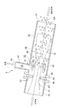
- FIG. 2 is a cross-sectional view showing a schematic configuration of the injection nozzle according to the embodiment.
- the injection nozzle 5 includes a first tubular portion 52, a throttle portion 53, and a second tubular portion 54.
- the first tubular portion 52 is formed in a tubular shape that defines the first flow passage 55 inside.
- a cleaning liquid introduction port 56 for introducing the cleaning liquid into the first flow passage 55, and a direction perpendicular to the flow direction of the cleaning liquid introduced from the cleaning liquid introduction port 56 and flowing through the first flow passage 55.
- a gas introduction port 57 for introducing the gas into the first flow path 55 and the discharge port 51 described above are formed along the direction.
- the discharge port 51 is provided to discharge the mixed fluid MF of the cleaning liquid introduced from the cleaning liquid introduction port 56 and the gas introduced from the gas introduction port 57.
- the first tubular portion 52 has a length direction along the direction in which the central axis CA of the discharge port 51 extends.
- the cleaning liquid inlet 56 described above is opened at one end in the length direction of the first tubular portion 52, and the above-mentioned discharge port 51 is opened at the other end in the length direction of the first tubular portion 52.
- the above-described gas introduction port 57 is opened on the outer periphery of the first tubular portion 52.
- the cleaning liquid sent from the cleaning liquid introduction line 41 into the first flow path 55 through the cleaning liquid introduction port 56 is discharged from the cleaning liquid introduction port 56 in the direction along the direction in which the central axis CA extends through the first flow path 55. It flows toward the discharge port 51.
- the second tubular portion 54 internally defines a second flow path 58 communicating with the gas introduction port 57, and at the same time, introduces a gas into the gas introduction port 57 (in the flow direction of the cleaning liquid).
- a second gas introduction port 59 is formed to extend along a direction orthogonal to the second flow path 58 and to introduce the gas into the second flow path 58.
- the second tubular portion 54 has a length direction along a direction orthogonal to the direction in which the central axis CA of the discharge port 51 extends.
- One end in the length direction of the second tubular portion 54 is integrally connected to the outer circumference of the first tubular portion 52. That is, the first tubular portion 52 and the second tubular portion 54 are integrally formed.
- the above-mentioned second gas introduction port 59 is opened at the other end in the length direction of the second tubular portion 54.
- the gas sent from the gas introduction line 42 into the second flow path 58 through the second gas introduction port 59 passes through the second flow path 58, and then inside the first flow path 55 through the gas introduction port 57. Sent to.
- the gas sent into the first flow channel 55 merges with the cleaning liquid at the merge section 60.
- the throttle unit 53 is provided on the upstream side of the confluence unit 60 in the flow direction of the cleaning liquid.
- the narrowed portion 53 has a contraction flow forming opening 61 through which the cleaning liquid flows, and the cross-sectional area of which is sharply reduced as compared with the upstream side and the downstream side in the flow direction of the cleaning liquid.
- the throttle portion 53 is configured to generate a negative pressure region 62 on the downstream side of the throttle portion 53 in the flow direction of the cleaning liquid by contracting the cleaning liquid by the contraction forming port 61.
- the injection nozzle 5 sucks the gas from the gas inlet 57 by the suction force generated in the negative pressure region 62.
- a pump (not shown) for sending gas to the first flow path 55 is provided in the gas introduction line 42, and the pump is provided. Therefore, the amount of gas sent to the first flow channel 55 may be increased.
- the throttle portion 53 is configured separately from the first tubular portion 52.
- the narrowed portion 53 may be formed integrally with the first tubular portion 52.
- the narrowed portion 53 may be provided so as to project from the inner peripheral surface of the first tubular portion 52 that defines the first flow path 55.
- the jet nozzle 5 shears and atomizes the gas sent to the first flow passage 55 by the cleaning liquid flowing through the first flow passage 55 to generate a mixed fluid MF (cleaning liquid containing fine bubbles inside). Further, the ejection nozzle 5 is adapted to eject the mixed fluid MF generated in the ejection nozzle 5 from the ejection port 51.
- the mixed fluid MF ejected from the ejection port 51 to the liquid reservoir 21B is in the direction in which the central axis CA of the ejection port 51 extends until reaching a predetermined jet flow reaching distance, as shown in FIG. 3 described later. Flowing along. At this time, the mixed fluid MF gradually increases in width as it moves away from the discharge port 51.
- the mixed fluid MF that has reached the predetermined jet arrival distance loses its momentum in the horizontal direction and flows vertically upward due to the buoyancy of the bubbles.
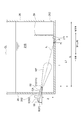
- FIG. 3 is an explanatory diagram for explaining an arrangement state of the injection nozzles in the embodiment.
- the tip of the first tubular portion 52 in which the ejection port 51 (first ejection port 51A) is formed in the insertion hole 252 formed in the first side wall 25. Includes the first injection nozzle 5A that is inserted from the outside of the first side wall 25.
- the exhaust gas desulfurization device 1 includes the absorption tower 2 including the liquid pool 21B described above and the gas-liquid mixing device 4 including the first injection nozzle 5A described above.
- the first injection nozzle 5A is arranged so that the central axis CA of the first ejection port 51A is inclined downward with respect to the horizontal plane.
- the intersection point between the virtual line IL extending the central axis CA of the first discharge port 51A and the bottom surface 211 of the liquid pool 21B is defined as P.
- the mixed fluid MF ejected from the first ejection port 51A of the first ejection nozzle 5A to the liquid pool portion 21B has a virtual line that extends the central axis CA of the first ejection port 51A until reaching a predetermined jet arrival distance. Flow along IL.
- the mixed fluid MF injected from the first injection nozzle 5A does not collide with the wall surface of the liquid pool 21B and is level. May lose momentum in the direction.
- the above-mentioned first injection nozzle 5A is arranged so that the above-mentioned virtual line IL and the bottom surface 211 of the liquid pool 21B intersect at an intersection point P. ..
- the gas G air bubbles
- the virtual line IL described above extends so as to intersect at the intersection P on the bottom surface 211 of the liquid reservoir 21B.
- the imaginary line IL does not extend to intersect the second side wall 26. Therefore, the mixed fluid MF injected from the first injection nozzle 5A and flowing along the imaginary line IL is directed to the bottom surface 211 of the liquid pool 21B and loses its momentum in the horizontal direction when colliding with the bottom surface 211. It is possible to prevent the mixed fluid MF from reaching the cleaning liquid outlet 262 of the second side wall 26. Therefore, according to the above configuration, it is possible to prevent the performance of the pump from being lowered due to the gas G being caught in the pump (the cleaning liquid circulation pump 72) for drawing the cleaning liquid from the liquid reservoir 21B.
- the absorption tower 2 described above further includes a bubble suppression member 29 arranged in the liquid pool portion 21B (internal space 21).
- the bubble suppression member 29 extends along a direction orthogonal to the first direction and has an intermediate line CL indicating the middle of the distance from the first ejection port 51A to the second side wall 26. It is provided at a position further away from the second side wall 26 and closer to the first side wall 25 than the second side wall 26.
- the bubble suppressing member 29 is formed in a plate shape having a plurality of through holes opened, and suppresses the flow of bubbles from the first side wall 25 side to the second side wall 26 side.
- the distance L1 satisfies the condition of 0.7L ⁇ L1 ⁇ 0.9L.
- the gas G air bubbles contained in the mixed fluid MF injected from the first injection nozzle 5A by the air bubble suppression member 29 provided at the position distant from the second side wall 26 to the first side wall 25 side. Can be prevented from reaching the cleaning liquid outlet 262 opening in the second side wall 26.
- FIG. 4 is a graph showing the relationship between the diving depth and the horizontal distance from the jet nozzle discharge port to the jet arrival point for each installation angle of the jet nozzle.
- the diving depth Z is the height from the bottom surface 211 of the liquid pool 21B to the ejection port 51 of the injection nozzle 5, as shown in FIG.
- the jet arrival point is an intersection P of an imaginary line IL extending the central axis CA of the discharge port 51 and a plane including the bottom surface 211 of the liquid pool 21B.
- the horizontal distance from the ejection port 51 of the ejection nozzle 5 to the jet arrival point (intersection P) is I
- the installation angle of the ejection nozzle 5, that is, the inclination angle of the central axis CA of the ejection port 51 from the horizontal plane is ⁇ . ..
- the length L from the discharge port 51 to the second side wall 26 is in the range of 8 m or more and 20 m or less. Therefore, in FIG. 4, thick solid lines are drawn for reference, which are 4 m and 10 m, which are half of the upper and lower limits of the length L.
- the horizontal distance I becomes long. If the horizontal distance I is too long, the gas G (air bubbles) contained in the mixed fluid MF injected from the injection nozzle 5 opens to the side wall (second side wall 26) of the injection nozzle 5 facing the discharge port 51. The risk of getting caught in the pump (cleaning liquid circulating pump 72) for drawing the cleaning liquid from the liquid reservoir 21B through the outlet 262 increases.
- the horizontal distance I becomes short. If the horizontal distance I becomes too short, the risk of the mixed fluid MF injected from the injection nozzle 5 colliding with the bottom surface 211 of the liquid pool 21B at an early stage increases.
- the above-described first injection nozzle 5A satisfies the condition of 10° ⁇ 30° when the inclination angle of the central axis CA of the first ejection port 51A from the horizontal plane is ⁇ .
- the gas G (bubbles) contained in the mixed fluid MF injected from the first injection nozzle 5A is a liquid. It was found that the risk of getting caught in the pump (cleaning liquid circulating pump 72) for drawing the cleaning liquid from the trapped portion 21B increases. Further, when the inclination angle ⁇ of the first injection nozzle 5A is 30° or more, the mixed fluid MF injected from the first injection nozzle 5A collides with the bottom surface 211 of the liquid pool 21B at an early stage. It has been found that the reaching distance becomes shorter and the effective oxidation volume, which is the volume in which the oxidation reaction is promoted by the mixed fluid MF injected from the first injection nozzle 5A, decreases.
- the first injection nozzle 5A satisfies the condition that the inclination angle ⁇ is 10° ⁇ 30°, so that the oxidation effective volume is prevented from becoming smaller than the original oxidation effective volume that can be exhibited.
- the gas G air bubbles
- the pump cleaning liquid circulating pump 72
- FIG. 5 is a schematic view showing a state where the liquid pool portion and the injection nozzle of the absorption tower shown in FIG. 1 are viewed from above.
- the absorption tower 2 further includes a third side wall 30 and a fourth side wall 31. That is, the planar shape of the internal space 21 of the absorption tower main body 22 is formed in a rectangular shape defined by the first side wall 25, the second side wall 26, the third side wall 30, and the fourth side wall 31.
- Each of the third side wall 30 and the fourth side wall 31 extends along the direction (first direction) in which the first side wall 25 and the second side wall 26 are separated from each other in an upper surface view, and includes the liquid pool portion 21B.
- a part of the space 21 is defined.
- the fourth side wall 31 faces the third side wall 30 and is provided at a position away from the third side wall in a second direction which is a direction orthogonal to the first direction in a top view.
- a plurality of the above-mentioned first injection nozzles 5A are attached to the first side wall 25 of the absorption tower body 22.
- the plurality of first injection nozzles 5A are arranged at intervals in the second direction.
- a region where the oxidation reaction of the cleaning liquid is promoted by the mixed fluid MF ejected from the plurality of first ejection nozzles 5A is referred to as a first oxidation effective region EA1 (oxidation effective region).
- the first oxidation effective area EA1 is an area having a maximum length LE1 in the first direction and a maximum width WE1 in the second direction when the liquid pool 21B is viewed from above.
- the maximum length LE1 in the first direction is approximately the same as the jet reach distance of the mixed fluid MF jetted from the first jet nozzle 5A, and may be regarded as the same length as the jet reach distance.
- the maximum width WE1 in the second direction varies depending on the number of the first injection nozzles 5A attached to the first side wall 25. Further, in the illustrated embodiment, the maximum width WE1 in the second direction is the same as the length W from the third side wall 30 to the fourth side wall 31.
- FIG. 6 is a schematic view showing a state in which the liquid pool portion and the injection nozzle of the absorption tower in another embodiment are viewed from above.
- the length L0 from the first side wall 25 to the second side wall 26 is longer than the maximum length LE1 of the first oxidation effective area EA1
- the length L0 is smaller than that of the first oxidation effective area EA1.
- an oxidation ineffective area IA which is an area where the oxidation reaction is not promoted by the mixed fluid MF injected from the first injection nozzle 5A is formed. If the oxidation ineffective area IA is wide, there is a possibility that the oxidation in the liquid pool 21B will be insufficient by that much.
- the tip of the first tubular portion 52 in which the ejection port 51 (second ejection port 51B) is formed in the insertion hole 301 formed in the third side wall 30 is provided.
- the tip of the first tubular portion 52 having the discharge port 51 (third discharge port 51C) is inserted into at least one second injection nozzle 5B to be inserted and the insertion hole 311 formed in the fourth side wall 31.
- at least one third injection nozzle 5C that is configured to operate.
- the second injection nozzle 5B is configured to inject the mixed fluid MF into the liquid reservoir 21B from the second outlet 51B located in the liquid reservoir 21B.
- the second jet nozzle 5B is oriented so that the jetted mixed fluid MF flows along the second direction toward the fourth sidewall 31 side.
- the third injection nozzle 5C is configured to inject the mixed fluid MF into the liquid pool 21B from the third discharge port 51C located in the liquid pool 21B.
- 5 C of 3rd injection nozzles are orient
- a plurality of second injection nozzles 5B are attached to the third side wall 30 closer to the first side wall 25 than the bubble suppression member 29 in the first direction.
- the plurality of second injection nozzles 5B are arranged at intervals in the first direction.
- a plurality of third injection nozzles 5C are attached to the fourth side wall 31 closer to the first side wall 25 than the bubble suppression member 29 in the first direction.
- the plurality of third injection nozzles 5C are arranged at intervals in the first direction.
- the second oxidation effective area EA2 is an area having a maximum length WE2 in the second direction and a maximum width LE2 in the first direction when the liquid pool 21B is viewed from above.
- a region where the oxidation reaction of the cleaning liquid is promoted by the mixed fluid MF ejected from the plurality of third ejection nozzles 5C is referred to as a third oxidation effective region EA3 (oxidation effective region).
- the third oxidation effective area EA3 is an area having a maximum length WE3 in the second direction and a maximum width LE3 in the first direction when the liquid pool 21B is viewed from above.
- the maximum length WE2 of the second oxidation effective area EA2 and the maximum length WE3 of the third oxidation effective area EA3 reach the jet flow of the mixed fluid MF jetted from the second jet nozzle 5B and the third jet nozzle 5C, respectively.
- the length is almost the same as the distance, and may be regarded as the same as the jet reaching distance.
- the maximum width LE2 of the second oxidation effective area EA2 and the maximum width LE3 of the third oxidation effective area EA3 respectively vary depending on the number of injection nozzles 5 attached to the side walls (third side wall 30, fourth side wall 31).
- the sum of the first oxidation effective area EA1 and the maximum length LE1 is shorter than the distance L1 from the first ejection port 51A to the bubble suppression member 29 in the first direction. Therefore, the mixed fluid MF is prevented from reaching the second side wall 26.
- the jet nozzle 5 of the gas-liquid mixing device 4 described above further includes the second jet nozzle 5B described above and the third jet nozzle 5C described above.
- the second injection nozzle 5B and the third injection nozzle 5C respectively inject the areas (oxidation ineffective areas IA) in the liquid pool portion 21B where the mixed fluid MF injected from the first injection nozzle 5A cannot promote the oxidation reaction.
- the oxidation reaction can be promoted by the mixed fluid MF. That is, since the second oxidation effective area EA2 and the third oxidation effective area EA3 are formed in the oxidation ineffective area IA described above, the area where the oxidation reaction cannot be promoted by the mixed fluid MF can be reduced. Therefore, according to the above configuration, it is possible to reduce the region in the liquid pool 21B where the mixed fluid MF cannot promote the oxidation reaction, and thus it is possible to prevent insufficient oxidation by the mixed fluid MF.
- each of the second injection nozzle 5B and the third injection nozzle 5C described above is arranged at a position separated from the first side wall 25 by a predetermined distance L2 or more.
- the predetermined distance L2 is longer than the maximum length LE1 of the first oxidation effective area EA1.
- the second jet nozzle 5B and the third jet nozzle 5C are not separated from each other. It is possible to prevent the mixed fluid MF injected from each of them from blocking the flow of the mixed fluid MF injected from the first injection nozzle 5A.
- the oxidation effect which is the volume in which the oxidation reaction is promoted by the mixed fluid MF injected from the first injection nozzle 5A. It is possible to prevent the volume from becoming small.
- each of the second injection nozzle 5B and the third injection nozzle 5C described above is arranged at a position separated from the second side wall 26 by a predetermined distance L3 or more.
- the predetermined distance L3 is longer than the length from the second side wall 26 to the bubble suppression member 29.
- the second jet nozzle 5B and the third jet nozzle 5C are not separated from each other. It is possible to prevent the mixed fluids MF injected from each of them from reaching the cleaning liquid outlet 262 of the second side wall 26. Therefore, according to the above configuration, it is possible to prevent the performance of the pump from being lowered due to the gas G (air bubbles) being caught in the pump (cleaning liquid circulating pump 72) for drawing the cleaning liquid from the liquid reservoir 21B. ..
- FIG. 7 is an explanatory diagram for explaining the respective arrangement states of the injection nozzles shown in FIG. 6.
- each of the second jet nozzle 5B and the third jet nozzle 5C described above is arranged at a different height position from the first jet nozzle 5A described above. ..
- each of the second jet nozzle 5B and the third jet nozzle 5C is arranged at a position lower than that of the first jet nozzle 5A. That is, each of the diving depth Z2 of the second jet nozzle 5B and the diving depth Z3 of the third jet nozzle 5C is shorter than the diving depth Z1 of the first jet nozzle 5A.
- the inclination angle ⁇ 2 of the second injection nozzle 5B and the inclination angle ⁇ 3 of the third injection nozzle 5C may be smaller than the inclination angle ⁇ 1 of the first injection nozzle 5A.
- Each of the second jet nozzle 5B and the third jet nozzle 5C is configured to jet the mixed fluid MF along a second direction that intersects the first direction in which the first jet nozzle 5A jets the mixed fluid MF in a top view. It has become. If each of the second jet nozzle 5B and the third jet nozzle 5C is arranged at the same height position as the first jet nozzle 5A, the mixture jetted from each of the second jet nozzle 5B and the third jet nozzle 5C is mixed. The fluid MF may hinder the flow of the mixed fluid MF ejected from the first ejection nozzle 5A.
- each of the second jet nozzle 5B and the third jet nozzle 5C is arranged at a height position different from that of the first jet nozzle 5A, so that the second jet nozzle 5B and the third jet nozzle 5C are provided. It is possible to prevent the mixed fluid MF jetted from each of the above from blocking the flow of the mixed fluid MF jetted from the first jet nozzle 5A. Further, by preventing the flow of the mixed fluid MF injected from the first injection nozzle 5A from being obstructed, it is possible to prevent the effective oxidation volume from decreasing.
- each of the second injection nozzle 5B and the third injection nozzle 5C is arranged at a position lower than the first injection nozzle 5A, but in another embodiment, the second injection nozzle 5B and the third jet nozzle 5C may be arranged at positions higher than the first jet nozzle 5A. That is, each of the diving depth Z2 of the second jet nozzle 5B and the diving depth Z3 of the third jet nozzle 5C may be made longer than the diving depth Z1 of the first jet nozzle 5A. In this case, the inclination angle ⁇ 2 of the second injection nozzle 5B and the inclination angle ⁇ 3 of the third injection nozzle 5C may be larger than the inclination angle ⁇ 1 of the first injection nozzle 5A.
- FIG. 8 is a partial cross-sectional view schematically showing the vicinity of a portion of the absorption tower where the injection nozzle is fixed.
- a method of mounting the injection nozzle 5 will be described with reference to FIG.
- the mounting method of the first jet nozzle 5A will be described as an example, the mounting method of the second jet nozzle 5B and the third jet nozzle 5C is the same as the mounting method of the first jet nozzle 5A.
- the tip of the first tubular portion 52 having the ejection port 51 (first ejection port 51A) of the first injection nozzle 5A is inserted into the insertion hole 252 formed so as to penetrate the first side wall 25. ..
- the first injection nozzle 5A includes a first tubular portion 52 and a discharge port side fastening portion 63 (first fastening portion).
- the first tubular portion 52 extends along the central axis CA of the first ejection port 51A, and the first ejection port 51A is formed at one end in the extending direction.
- the discharge port side fastening portion 63 is on the downstream side of the connection portion of the first tubular portion 52 with the second tubular portion 54 and the confluence portion 60 in the flow direction of the cleaning liquid, and is upstream of the first discharge port 51A. It is provided on the outer periphery of the side.
- the ejection port side fastening portion 63 is provided so as to project from the outer periphery of the first tubular portion 52 along the direction orthogonal to the central axis CA of the first ejection port 51A.
- the absorption tower 2 includes a cylindrical protrusion 32 and an injection nozzle fastening portion 33 (second fastening portion).
- the cylindrical protruding portion 32 extends along the direction inclined by the angle ⁇ from the horizontal plane.
- the side wall 25 is provided so as to project outward from the peripheral edge of the insertion hole 252.
- the injection nozzle fastening portion 33 is provided so as to project from the tip of the tubular protruding portion 32 along a direction orthogonal to the direction in which the tubular protruding portion 32 extends.
- the first injection nozzle 5A is fixed to the first side wall 25.
- the discharge port side fastening portion 63 of the first jet nozzle 5A is fixed to the jet nozzle fastening portion 33 of the absorption tower 2 by a fastening device 66 (66A).
- the fastening device 66A includes a bolt 67 (67A) and a nut 68 (68A).
- the bolt 67 (67A) includes a shaft portion 671 having a threaded portion formed on at least a part of the outer peripheral surface thereof, and a head portion 672 formed at a base end portion of the shaft portion 671 having a diameter larger than that of the shaft portion 671.
- the shaft portion 671 is inserted from one side in the extending direction of the tubular protruding portion 32 into the through holes 631 and 331 formed in the discharge port side fastening portion 63 and the injection nozzle fastening portion 33, and
- the first injection nozzle 5A is fixed to the first side wall 25 by screwing the tip of the shaft portion 671 inserted into the other side in the extending direction of the protruding portion 32 into the nut 68A.
- the gas introduction line 42 is connected to the first injection nozzle 5A.
- the first injection nozzle 5A is provided so as to project from the outer periphery of the end of the second tubular portion 54 where the second gas introduction port 59 is formed, as shown in FIG.
- the introduction side fastening part 64 is further included.
- the gas introduction line 42 includes a gas introduction pipe 47 extending along the extending direction of the second tubular portion 54.
- the gas introduction pipe 47 includes a gas downstream-side fastening portion 48 that is provided so as to project from the outer circumference of the end portion where the opening communicating with the second gas introduction port 59 is formed.
- the gas downstream side fastening portion 48 of the gas introduction pipe 47 is fixed to the gas introduction side fastening portion 64 of the first injection nozzle 5A by a fastening device 66 (66B).
- the fastening device 66B includes a bolt 67B having a configuration similar to the bolt 67A and a nut 68B having a configuration similar to the nut 68A.
- the nut 68B is screwed to the tip of the shaft portion 671 inserted into the through holes 641 and 481 formed in the gas introduction side fastening portion 64 and the gas downstream side fastening portion 48, whereby the first injection nozzle 5A.
- the gas introducing pipe 47 is fixed to the second tubular portion 54 of the.
- the cleaning liquid introduction line 41 is connected to the first jet nozzle 5A.
- the connection between the cleaning liquid introduction line 41 and the first injection nozzle 5A may be performed at the same time as the connection between the gas introduction line 42 and the first injection nozzle 5A, or from the connection between the gas introduction line 42 and the first injection nozzle 5A. May go before or after.
- the first injection nozzle 5A further includes a cleaning liquid introduction side fastening portion 65 provided so as to project from the outer periphery of the end of the first tubular portion 52 where the cleaning liquid introduction port 56 is formed.
- the cleaning liquid introduction line 41 includes a cleaning liquid introduction pipe 45 extending along the direction in which the first tubular portion 52 extends.
- the cleaning liquid introduction pipe 45 is provided with a cleaning liquid downstream side fastening portion provided so as to project from the outer periphery of the end portion where the opening 451 communicating with the cleaning liquid introduction port 56 sandwiching the narrowed portion 53 is formed. 46 is provided.
- the cleaning liquid downstream side fastening portion 46 of the cleaning liquid introduction pipe 45 is fixed to the cleaning liquid introduction side fastening portion 65 of the first injection nozzle 5A by a fastening device 66C.
- the fastening device 66C includes a bolt 67C having a configuration similar to the bolt 67A, and a nut 68C having a configuration similar to the nut 68A.
- the bolt 67C is configured such that the nut 68C is screwed into the tip of the shaft portion 671 inserted into the through holes 651 and 461 formed in the cleaning liquid introduction side fastening portion 65 and the cleaning liquid downstream side fastening portion 46, whereby the first tubular portion is formed.
- the cleaning liquid introduction pipe 45 is fixed to the first tubular portion 52 of the first injection nozzle 5A with the narrowed portion 53 sandwiched between the 52 and the cleaning liquid introduction pipe 45.
- the above-described first injection nozzle 5A includes the above-described first tubular portion 52 and the above-described discharge port side fastening portion 63 (first fastening portion).
- the above-mentioned absorption tower 2 contains the above-mentioned cylindrical projection part 32 and the above-mentioned injection nozzle fastening part 33 (2nd fastening part).
- the first injection nozzle 5A is in a state in which the tip including the first ejection port 51A of the first tubular portion 52 is inserted into the insertion hole 252 formed in the first side wall 25 of the absorption tower 2.
- the discharge port side fastening portion 63 is fixed to the injection nozzle fastening portion 33 of the absorption tower 2 by the fastening device 66 (66A).
- the first tubular portion 52 extends along the central axis CA of the first ejection port 51A.
- the cylindrical protrusion 32 of the absorption tower 2 extends along the direction inclined from the horizontal plane by the same angle as the inclination angle ⁇ of the central axis CA of the first discharge port 51A from the horizontal plane.
- the cylindrical protrusion 32 of the absorption tower 2 extends along the same direction as the central axis CA of the first discharge port 51A when the first injection nozzle 5A is installed.
- the first injection nozzle 5A has a discharge port side fastening portion 63 extending along a direction orthogonal to the extending direction of the first tubular portion 52, and a direction orthogonal to the extending direction of the tubular protruding portion 32.
- the present invention is not limited to the above-described embodiment, and includes a form in which the above-described embodiment is modified and a form in which these forms are appropriately combined.
- the exhaust gas discharge part 24 is provided on the opposite side of the exhaust gas main body part 22 from the exhaust gas introduction part 23 in the first direction. It may be provided on the same side. Further, the exhaust gas discharge part 24 may be provided so as to be adjacent to the absorption tower main body part 22 in the second direction orthogonal to the first direction in a top view.
Landscapes
- Chemical & Material Sciences (AREA)
- Chemical Kinetics & Catalysis (AREA)
- Engineering & Computer Science (AREA)
- Analytical Chemistry (AREA)
- General Chemical & Material Sciences (AREA)
- Oil, Petroleum & Natural Gas (AREA)
- Environmental & Geological Engineering (AREA)
- Health & Medical Sciences (AREA)
- Biomedical Technology (AREA)
- Treating Waste Gases (AREA)
- Gas Separation By Absorption (AREA)
Abstract
Le dispositif de désulfuration des gaz de combustion de l'invention est équipé : d'une colonne d'absorption qui est configurée de manière à mettre en contact la solution nettoyante avec un gaz de combustion, et qui contient dans sa partie interne une partie rétention de liquide dans laquelle la solution nettoyante est stockée ; et d'un dispositif de mélange gaz/liquide dont l'extrémité avant est insérée dans un orifice d'insertion formé dans une première paroi latérale de la colonne d'absorption, et qui contient une première buse d'injection configurée de sorte qu'un mélange fluide à base d'un gaz contenant un oxygène et de la solution nettoyante provenant d'une première ouverture de décharge est injecté dans la partie rétention. La première buse d'injection contient une partie tubulaire, et une première partie fixation qui est agencée de manière à faire saillie depuis la périphérie externe de la partie tubulaire dans une direction perpendiculaire à un axe central de la première ouverture de décharge. La colonne d'absorption contient en outre : une partie saillie tubulaire qui suit la direction d'inclinaison selon un angle (θ) par rapport à un plan horizontal, lorsque l'angle d'inclinaison de l'axe central de la première ouverture de décharge par rapport à un plan horizontal est représenté par θ, et qui est agencée en saillie côté externe d'une partie bord périphérique de l'orifice d'insertion formé dans la première paroi latérale ; et une seconde partie fixation qui est agencée en saillie depuis l'extrémité avant de la partie saillie tubulaire suivant une direction perpendiculaire à la direction de prolongement de la partie saillie tubulaire, et qui est configurée de manière à être immobilisée sur la première partie fixation au moyen d'un dispositif de fixation.
Priority Applications (2)
| Application Number | Priority Date | Filing Date | Title |
|---|---|---|---|
| DE112019005624.7T DE112019005624T5 (de) | 2018-12-11 | 2019-05-23 | Abgasentschwefelungsvorrichtung |
| KR1020217016935A KR20210082254A (ko) | 2018-12-11 | 2019-05-23 | 배기가스 탈황 장치 |
Applications Claiming Priority (2)
| Application Number | Priority Date | Filing Date | Title |
|---|---|---|---|
| JP2018231382A JP6588147B1 (ja) | 2018-12-11 | 2018-12-11 | 排ガス脱硫装置 |
| JP2018-231382 | 2018-12-11 |
Publications (1)
| Publication Number | Publication Date |
|---|---|
| WO2020121552A1 true WO2020121552A1 (fr) | 2020-06-18 |
Family
ID=68159754
Family Applications (1)
| Application Number | Title | Priority Date | Filing Date |
|---|---|---|---|
| PCT/JP2019/020478 Ceased WO2020121552A1 (fr) | 2018-12-11 | 2019-05-23 | Dispositif de désulfuration des gaz de combustion |
Country Status (5)
| Country | Link |
|---|---|
| JP (1) | JP6588147B1 (fr) |
| KR (1) | KR20210082254A (fr) |
| DE (1) | DE112019005624T5 (fr) |
| TW (1) | TWI735030B (fr) |
| WO (1) | WO2020121552A1 (fr) |
Cited By (1)
| Publication number | Priority date | Publication date | Assignee | Title |
|---|---|---|---|---|
| CN114904366A (zh) * | 2021-02-08 | 2022-08-16 | 中国石油化工股份有限公司 | 含气危化品泄漏高效应急处理装置及方法 |
Citations (8)
| Publication number | Priority date | Publication date | Assignee | Title |
|---|---|---|---|---|
| JPH10235143A (ja) * | 1997-02-26 | 1998-09-08 | Babcock Hitachi Kk | 湿式排煙脱硫装置 |
| JP2002210326A (ja) * | 2000-11-17 | 2002-07-30 | Mitsubishi Heavy Ind Ltd | 湿式排煙脱硫装置、及び、湿式排煙脱硫方法 |
| JP3486399B2 (ja) * | 1998-08-11 | 2004-01-13 | 三菱重工業株式会社 | 湿式排煙脱硫装置 |
| JP2012005978A (ja) * | 2010-06-25 | 2012-01-12 | Mitsubishi Heavy Ind Ltd | 噴霧装置及び水銀除去システム |
| JP2012179533A (ja) * | 2011-02-28 | 2012-09-20 | Mitsubishi Heavy Ind Ltd | 排煙脱硫装置 |
| JP5046755B2 (ja) * | 2007-06-27 | 2012-10-10 | 三菱重工業株式会社 | 気液接触装置 |
| WO2014021068A1 (fr) * | 2012-07-30 | 2014-02-06 | 三菱重工業株式会社 | Équipement de désulfurisation de gaz effluent humide |
| WO2017014200A1 (fr) * | 2015-07-23 | 2017-01-26 | 三菱日立パワーシステムズ株式会社 | Dispositif de désulfuration de gaz de combustion de type par voie humide et procédé d'exploitation d'un dispositif de désulfuration de gaz de combustion de type par voie humide |
-
2018
- 2018-12-11 JP JP2018231382A patent/JP6588147B1/ja active Active
-
2019
- 2019-05-23 DE DE112019005624.7T patent/DE112019005624T5/de not_active Ceased
- 2019-05-23 KR KR1020217016935A patent/KR20210082254A/ko not_active Ceased
- 2019-05-23 WO PCT/JP2019/020478 patent/WO2020121552A1/fr not_active Ceased
- 2019-08-21 TW TW108129798A patent/TWI735030B/zh active
Patent Citations (8)
| Publication number | Priority date | Publication date | Assignee | Title |
|---|---|---|---|---|
| JPH10235143A (ja) * | 1997-02-26 | 1998-09-08 | Babcock Hitachi Kk | 湿式排煙脱硫装置 |
| JP3486399B2 (ja) * | 1998-08-11 | 2004-01-13 | 三菱重工業株式会社 | 湿式排煙脱硫装置 |
| JP2002210326A (ja) * | 2000-11-17 | 2002-07-30 | Mitsubishi Heavy Ind Ltd | 湿式排煙脱硫装置、及び、湿式排煙脱硫方法 |
| JP5046755B2 (ja) * | 2007-06-27 | 2012-10-10 | 三菱重工業株式会社 | 気液接触装置 |
| JP2012005978A (ja) * | 2010-06-25 | 2012-01-12 | Mitsubishi Heavy Ind Ltd | 噴霧装置及び水銀除去システム |
| JP2012179533A (ja) * | 2011-02-28 | 2012-09-20 | Mitsubishi Heavy Ind Ltd | 排煙脱硫装置 |
| WO2014021068A1 (fr) * | 2012-07-30 | 2014-02-06 | 三菱重工業株式会社 | Équipement de désulfurisation de gaz effluent humide |
| WO2017014200A1 (fr) * | 2015-07-23 | 2017-01-26 | 三菱日立パワーシステムズ株式会社 | Dispositif de désulfuration de gaz de combustion de type par voie humide et procédé d'exploitation d'un dispositif de désulfuration de gaz de combustion de type par voie humide |
Cited By (2)
| Publication number | Priority date | Publication date | Assignee | Title |
|---|---|---|---|---|
| CN114904366A (zh) * | 2021-02-08 | 2022-08-16 | 中国石油化工股份有限公司 | 含气危化品泄漏高效应急处理装置及方法 |
| CN114904366B (zh) * | 2021-02-08 | 2023-06-16 | 中国石油化工股份有限公司 | 含气危化品泄漏高效应急处理装置及方法 |
Also Published As
| Publication number | Publication date |
|---|---|
| TWI735030B (zh) | 2021-08-01 |
| KR20210082254A (ko) | 2021-07-02 |
| JP6588147B1 (ja) | 2019-10-09 |
| DE112019005624T5 (de) | 2021-07-29 |
| JP2020093191A (ja) | 2020-06-18 |
| TW202021656A (zh) | 2020-06-16 |
Similar Documents
| Publication | Publication Date | Title |
|---|---|---|
| KR101570466B1 (ko) | 배기 가스 처리 장치 | |
| US9550145B2 (en) | Exhaust gas treatment apparatus, ship, and exhaust gas treatment method | |
| KR101959401B1 (ko) | 배기가스 처리장치의 배출 세정액 내의 유해가스 제거 시스템 및 방법 | |
| JP5983802B2 (ja) | 排ガス処理装置 | |
| KR101857216B1 (ko) | 배기가스 처리 시스템 | |
| WO2002040137A1 (fr) | Procede et appareil de desulfuration des gaz de combustion de type sature | |
| JP3073972B2 (ja) | 排煙脱硫装置 | |
| WO2020121552A1 (fr) | Dispositif de désulfuration des gaz de combustion | |
| JP6559873B1 (ja) | 気液混合装置、および気液混合装置を備える排ガス脱硫装置 | |
| WO2018159557A1 (fr) | Dispositif de désulfuration de navire et bateau sur lequel le dispositif de désulfuration de navire est monté | |
| CN111892182B (zh) | 一种船舶脱硫洗涤水循环舱、船舶脱硫系统以及船舶 | |
| WO2020121554A1 (fr) | Dispositif de mélange gaz/liquide, et dispositif de désulfuration des gaz de combustion équipé de celui-ci | |
| KR102497047B1 (ko) | 노즐 구조체 | |
| TWI802860B (zh) | 脫硫裝置的吸收塔 | |
| JP3382837B2 (ja) | 排煙脱硫装置の空気吹込み装置 | |
| JP7280699B2 (ja) | 液柱式吸収塔の改造方法および液柱式吸収塔 | |
| JP7022818B2 (ja) | 脱硫装置 | |
| KR20180127581A (ko) | 향상된 공간활용도를 가진 하이브리드형 배기가스 처리 시스템 | |
| KR101964959B1 (ko) | 위치정보 기반 세정액 공급 방식 자동 제어 하이브리드형 배기가스 처리 시스템 |
Legal Events
| Date | Code | Title | Description |
|---|---|---|---|
| 121 | Ep: the epo has been informed by wipo that ep was designated in this application |
Ref document number: 19896196 Country of ref document: EP Kind code of ref document: A1 |
|
| ENP | Entry into the national phase |
Ref document number: 20217016935 Country of ref document: KR Kind code of ref document: A |
|
| 122 | Ep: pct application non-entry in european phase |
Ref document number: 19896196 Country of ref document: EP Kind code of ref document: A1 |