WO2020121978A1 - Matériau de gainage de couche externe pour échangeur de chaleur ayant une résistance à la corrosion exceptionnelle dans la portion de racine, et échangeur de chaleur - Google Patents
Matériau de gainage de couche externe pour échangeur de chaleur ayant une résistance à la corrosion exceptionnelle dans la portion de racine, et échangeur de chaleur Download PDFInfo
- Publication number
- WO2020121978A1 WO2020121978A1 PCT/JP2019/047912 JP2019047912W WO2020121978A1 WO 2020121978 A1 WO2020121978 A1 WO 2020121978A1 JP 2019047912 W JP2019047912 W JP 2019047912W WO 2020121978 A1 WO2020121978 A1 WO 2020121978A1
- Authority
- WO
- WIPO (PCT)
- Prior art keywords
- heat exchanger
- brazing
- corrosion resistance
- clad material
- potential
- Prior art date
- Legal status (The legal status is an assumption and is not a legal conclusion. Google has not performed a legal analysis and makes no representation as to the accuracy of the status listed.)
- Ceased
Links
Images

Classifications
-
- B—PERFORMING OPERATIONS; TRANSPORTING
- B23—MACHINE TOOLS; METAL-WORKING NOT OTHERWISE PROVIDED FOR
- B23K—SOLDERING OR UNSOLDERING; WELDING; CLADDING OR PLATING BY SOLDERING OR WELDING; CUTTING BY APPLYING HEAT LOCALLY, e.g. FLAME CUTTING; WORKING BY LASER BEAM
- B23K1/00—Soldering, e.g. brazing, or unsoldering
-
- B—PERFORMING OPERATIONS; TRANSPORTING
- B23—MACHINE TOOLS; METAL-WORKING NOT OTHERWISE PROVIDED FOR
- B23K—SOLDERING OR UNSOLDERING; WELDING; CLADDING OR PLATING BY SOLDERING OR WELDING; CUTTING BY APPLYING HEAT LOCALLY, e.g. FLAME CUTTING; WORKING BY LASER BEAM
- B23K35/00—Rods, electrodes, materials, or media, for use in soldering, welding, or cutting
- B23K35/22—Rods, electrodes, materials, or media, for use in soldering, welding, or cutting characterised by the composition or nature of the material
- B23K35/24—Selection of soldering or welding materials proper
- B23K35/28—Selection of soldering or welding materials proper with the principal constituent melting at less than 950°C
-
- C—CHEMISTRY; METALLURGY
- C22—METALLURGY; FERROUS OR NON-FERROUS ALLOYS; TREATMENT OF ALLOYS OR NON-FERROUS METALS
- C22C—ALLOYS
- C22C21/00—Alloys based on aluminium
-
- F—MECHANICAL ENGINEERING; LIGHTING; HEATING; WEAPONS; BLASTING
- F28—HEAT EXCHANGE IN GENERAL
- F28F—DETAILS OF HEAT-EXCHANGE AND HEAT-TRANSFER APPARATUS, OF GENERAL APPLICATION
- F28F19/00—Preventing the formation of deposits or corrosion, e.g. by using filters or scrapers
- F28F19/02—Preventing the formation of deposits or corrosion, e.g. by using filters or scrapers by using coatings, e.g. vitreous or enamel coatings
- F28F19/06—Preventing the formation of deposits or corrosion, e.g. by using filters or scrapers by using coatings, e.g. vitreous or enamel coatings of metal
-
- F—MECHANICAL ENGINEERING; LIGHTING; HEATING; WEAPONS; BLASTING
- F28—HEAT EXCHANGE IN GENERAL
- F28F—DETAILS OF HEAT-EXCHANGE AND HEAT-TRANSFER APPARATUS, OF GENERAL APPLICATION
- F28F21/00—Constructions of heat-exchange apparatus characterised by the selection of particular materials
- F28F21/08—Constructions of heat-exchange apparatus characterised by the selection of particular materials of metal
-
- F—MECHANICAL ENGINEERING; LIGHTING; HEATING; WEAPONS; BLASTING
- F28—HEAT EXCHANGE IN GENERAL
- F28F—DETAILS OF HEAT-EXCHANGE AND HEAT-TRANSFER APPARATUS, OF GENERAL APPLICATION
- F28F9/00—Casings; Header boxes; Auxiliary supports for elements; Auxiliary members within casings
- F28F9/02—Header boxes; End plates
Definitions
- the present invention relates to a heat exchanger multilayer clad material and a heat exchanger that have excellent corrosion resistance at the root after brazing.
- the header plate material for the heat exchanger an aluminum alloy composed of three layers, in which a core material, a brazing material for joining with other members, and a sacrificial material in contact with cooling water are laminated, is used (for example, see Patent Documents 1 to 3).
- the header plate material is required to have high strength, and an Al—Mn alloy is used for the core material, and the strength is improved by adding elements such as Mg and Cu.
- Mg forms an oxide film by combining with oxygen in the atmosphere during brazing and reduces the brazing property.
- Cu condenses into fillets formed at the joint between the header plate and the tube to make the electric potential noble, so that the tube near the joint where the electric potential is relatively base is penetrated early, which reduces corrosion resistance.
- a brazing sheet has been proposed in which the distribution of the Si-based precipitate and the eutectic phase of the brazing material after brazing is appropriately adjusted to significantly improve the corrosion resistance (see Patent Document 4).
- the present invention has been made in view of the above circumstances, and an object of the present invention is to provide a multilayer clad material for a heat exchanger and a heat exchanger that have high strength and excellent corrosion resistance at the root.
- the first mode is that each is made of an aluminum alloy, and at least a brazing material and a core material are laminated to form a brazing target material.
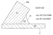
- a multilayer clad material for a heat exchanger to be brazed When the potential of the core material is E1, the potential of the eutectic braze of the fillet formed at the joint between the brazing target material and the multilayer clad material for heat exchanger is E3, and the potential of the brazing target material is E2, E3 ⁇ E1 ⁇ E2, and the potential difference ⁇ E A between E3 and E2 is 105 mV or more, and the potential difference ⁇ E B between E3 and E1 is 80 mV or more.
- Another aspect of the invention of a multilayer clad material for a heat exchanger having excellent corrosion resistance of a root portion is the invention of the above aspect, in which the core material is mass%, Mn: 1.2 to 2.0%, Cu: 0. 3 to 1.0%, Si: 0.5 to 1.2%, with the balance being Al and inevitable impurities.
- Another aspect of the invention is a multilayer clad material for a heat exchanger, which has excellent corrosion resistance of a rooted portion, in the invention of the above aspect, the brazing filler metal is mass%, Si: 5.0 to 12.0%, Zn: 1 0.0 to 5.0%, with the balance being Al and unavoidable impurities.
- the invention of a multilayer clad material for a heat exchanger having excellent corrosion resistance of a rooted portion of another aspect is that in the invention of the aspect, a sacrificial material is laminated on the other surface side of the core material on which a brazing material is laminated. Is characterized by.
- Another aspect of the invention of a multilayer clad material for a heat exchanger having excellent corrosion resistance of a root portion is the invention of the above aspect, in which the sacrificial material is mass%, Mn: 1.2 to 2.0%, Si:0. 0.5 to 1.2%, Zn: 0.05 to 0.5%, with the balance being Al and inevitable impurities.
- the sacrificial material is arranged in contact with the packing when used for a heat exchanger.
- the sacrificial material is an Al—Mn—Si-based compound having a circle equivalent diameter of 0.1 ⁇ m to 0.5 ⁇ m. 1 to 100/ ⁇ m 2 .
- Another aspect of the invention of a multilayer clad material for a heat exchanger, which has excellent corrosion resistance of a rooted portion, is the same as the multilayer clad material for a heat exchanger according to the invention of the above aspect, to which a working strain of 2 to 8% is applied during brazing.
- the erosion rate of the wax is 10% or less of the plate thickness.
- the recrystallized grain size of the core material after brazing is 40 ⁇ m or more in the direction horizontal to the rolling direction. ..
- the brazing holding temperature is 590°C to 610°C in the above aspect of the invention.
- the core material to be brazed is an Al—Mn-based alloy, and in a mass %, Cu:0. 0.1 to 1.0% is contained.
- the material is used as a header plate, and the brazing target material is a tube material.
- the header plate made of the multilayer clad material for heat exchangers of any of the above aspects and the tube to be brazed are joined by brazing.
- each component is shown by mass %.
- the potential difference ⁇ E A between E3 and E2 is 105 mV or more
- the potential difference ⁇ E B between E3 and E1 is 80 mV or more.
- the eutectic braze does not preferentially corrode, but corrodes the core material. Therefore, the relationship of each potential is defined as above.
- the potential can be measured, for example, by the following method.
- the potential is the pitting potential obtained by the following method. For example, 10 mm 2 of the measurement portion of each portion subjected to the heat treatment for brazing and the conductive portion were exposed, and the other portions were covered with an insulating paint.
- an aqueous solution containing 2.67% of AlCl 3 is used, platinum is used for the counter electrode, and saturated calomel is used for the reference electrode. Since the saturated calomel reference electrode affects the aqueous solution used, the aqueous solution saturated with KCl was bypassed. The atmosphere is flushed with N 2 gas for 20 minutes to eliminate the effect of dissolved oxygen.
- the temperature of the aqueous solution is kept at 40° C. in a constant temperature bath. After holding at the natural potential for about 5 minutes, the speed is set to 0.5 mV/sec and the potential is swept by 1000 mV. As the pitting potential, the electric potential at the point connecting the respective tangents to the passive state holding current density and the subsequent point where the current flows is selected, and the potential difference is calculated based on the obtained potential. In some samples containing Zn, passivation could not be confirmed depending on the added amount of Zn, and in that case, a potential of 1 mA/cm 2 was selected.
- Mn (Heartwood) Mn: 1.2-2.0% Mn is contained in order to improve the strength of the core material.
- the Mn content is less than 1.2%, the Mn content is so small that the strength of the material after brazing decreases, and the pressure resistance of the heat exchanger becomes insufficient, and the desired effect cannot be obtained.
- the Mn content exceeds 2.0%, the manufacturability (castability, rollability) deteriorates. For this reason, when Mn is contained, it is desirable to set it within the above range. For the same reason, it is desirable that the lower limit of the Mn content is 1.5% and the upper limit thereof is 1.8%.
- Si 0.5-1.2% Si is contained to improve the strength of the core material.
- Si content if the Si content is less than 0.5%, the Si content is small and the strength of the material after brazing is reduced, so that the pressure resistance of the heat exchanger is insufficient and the desired effect cannot be obtained.
- Si content exceeds 1.2%, the melting point is lowered and the brazing property is lowered. Therefore, when Si is contained, it is desirable to set it within the above range. For the same reason, it is desirable that the Si content has a lower limit of 0.8% and an upper limit of 1.0%.
- Cu 0.3-1.0% Cu is contained to improve the strength of the core material. However, if the Cu content is less than 0.3%, the content is too small to obtain the desired effect. On the other hand, when the Cu content exceeds 1.0%, the melting point decreases. For this reason, when Cu is contained, it is desirable to set it within the above range. For the same reason, it is desirable that the lower limit of the Cu content be 0.7% and the upper limit thereof be 0.9%.
- the recrystallized grain size of the core material after brazing is 40 ⁇ m or more and the recrystallized grain size is less than 40 ⁇ m in the direction horizontal to the rolling direction, the molten braze will corrode into the core material during brazing, and it will be necessary for fillet formation. Can't get Therefore, the recrystallized grain size is set to 40 ⁇ m or more.
- the homogenizing temperature of the core material is appropriately selected. For example, it can be selected at 500° C. to 600° C. for 1 to 10 hours. As the brazing holding temperature, 600° C. ⁇ 5 minutes can be shown as an example.
- the recrystallized grain size may be 200 ⁇ m so that the strength does not decrease after brazing.
- brazing material In the clad material of the present invention, a brazing material having an appropriate composition is used.
- the composition of the brazing material is not limited to a particular one, but the following can be shown as suitable components.
- Si: 5.0-12.0% Si improves brazeability.
- the Si content of the brazing material be within the above range.
- the lower limit of the Si content be 6% and the upper limit thereof be 9%.
- Zn 1.0-5.0% Zn improves the corrosion resistance and is included. However, if the content is less than 1.0%, the content is small, the potential of the fillet formed at the joint between the core material and the brazing target material becomes noble, and the potential difference between the fillet and the brazing target material becomes small, so sufficient corrosion resistance is obtained. I can't get it. On the other hand, when the Zn content exceeds 5.0%, the electric potential becomes base and the corrosion weight loss increases. Therefore, it is desirable that the Zn content of the brazing material be within the above range. For the same reason, it is preferable that the Zn content has a lower limit of 2.0% and an upper limit of 4.0%.
- Zn is added to the brazing material as a clad material having excellent corrosion resistance even in a material in which a large amount of Cu is added to the core material.
- Zn which has a base material potential, can provide a sacrificial anode action.
- Zn is concentrated in the fillet formed at the joint between the clad material and the material to be brazed, the potential of which has become noble due to the concentration of Cu, so that the potential of the fillet becomes base.
- a potential difference of E3 ⁇ E1 ⁇ E2 can be obtained. Therefore, it is possible to solve the deterioration of the corrosion resistance due to Cu added to the core material for increasing the strength.
- the clad material of the present invention may be a stack of sacrificial materials.
- the sacrificial material of the present invention is not limited to a specific composition, but the following can be shown as suitable components.
- Mn 1.2-2.0% Mn improves the strength of the sacrificial material and further improves the corrosion resistance, so it is contained. However, if the Mn content is less than 1.2%, the strength of the material after brazing decreases, and the pressure resistance of the heat exchanger becomes insufficient, and the desired effect cannot be obtained. On the other hand, if the Mn content exceeds 2.0%, the manufacturability (castability, rollability) deteriorates. Therefore, it is desirable that the Mn content be within the above range. For the same reason, it is desirable that the lower limit of the Mn content is 1.5% and the upper limit thereof is 1.8%.
- Si 0.5-1.2% Si is contained because it improves the strength of the sacrificial material and further improves the corrosion resistance.
- the Si content is less than 0.5%, the Si content is small and the strength of the material after brazing is reduced, so that the pressure resistance of the heat exchanger is insufficient and the desired effect cannot be obtained.
- it exceeds 1.2% the melting point is lowered, resulting in poor brazing. Therefore, it is desirable that the Si content be within the above range. For the same reason, it is desirable that the Si content has a lower limit of 0.8% and an upper limit of 1.0%.
- Zn 0.05-0.5% Zn is contained because it improves the corrosion resistance. However, if the Zn content is less than 0.05%, the content is too small to obtain the desired effect. On the other hand, when the Zn content exceeds 0.5%, the electric potential becomes base and the corrosion weight loss increases. Therefore, the Zn content is set within the above range. For the same reason, it is desirable that the lower limit of the Zn content be 0.3% and the upper limit thereof be 0.5%.
- Al-Mn-Si compound having a circle equivalent diameter of 0.1 ⁇ m to 0.5 ⁇ m: 1 to 100/ ⁇ m 2 If the size of the above compound is less than the equivalent circle diameter of 0.1 ⁇ m, the strength of the material after brazing decreases, and the pressure resistance of the heat exchanger becomes insufficient, and the desired effect cannot be obtained. If the equivalent circle diameter exceeds 0.5 ⁇ m, the corrosion resistance of the sacrificial material deteriorates, and the strength of the material after brazing decreases, so that the pressure resistance of the heat exchanger becomes insufficient and the desired effect cannot be obtained.
- the corrosion resistance after brazing is reduced, and the strength of the material is reduced, so that the pressure resistance of the heat exchanger is insufficient and the desired effect cannot be obtained.
- it exceeds 100 pieces/ ⁇ m 2 the corrosion resistance of the sacrificial material deteriorates, and the strength of the material after brazing decreases, so that the pressure resistance of the heat exchanger becomes insufficient and the desired effect cannot be obtained.
- the temperature of the subsequent heat treatment is preferably as low as possible in order to suppress the growth of the compound.
- the heat treatment may be performed in a batch annealing furnace at 300° C. to 450° C. for 1 to 10 hours.
- the size and number of compounds can be measured, for example, by the following method.
- a cross section parallel to the rolling direction of the brazed material is processed by using an ion milling method.
- the distribution state of the Al—Mn—Si compound in the sacrificial material is observed using a general-purpose scanning electron microscope. It is desirable to use an FE-SEM as the facility for observation so that the magnification is 10,000 to 50,000 times.
- a photograph containing at least 20 pieces in one visual field is taken, for example, about 10 visual fields.
- the area of the Al-Mn-Si-based compound was binarized in the obtained photograph and obtained by separating the particles and the base material.
- the equivalent circle diameter is calculated from the area of the obtained compound.
- a tube material is typically mentioned.
- an Al-Mn-based alloy can be used, and a material containing Cu: 0.1 to 1.0% by mass% can be shown. Since the material brazed to the header plate is generally a tube material, the above materials are typically mentioned. Al-Mn alloy is often used as the core material of the tube material, and when Cu:0.1-1.0% is contained, the potential balance is established between the header and the fillet (it becomes the most precious). ..
- the brazing object material is not limited to the above.
- the present invention by appropriately determining the potentials of the core material, the material to be brazed, and the eutectic braze, it is possible to obtain excellent corrosion resistance while maintaining high strength.
- the aluminum alloy for the core material, the aluminum alloy for the sacrificial material, and the aluminum alloy for the brazing material are cast by semi-continuous casting.
- the aluminum alloy for the core material for example, Mn: 1.2 to 2.0%, Cu: 0.3 to 1.0%, Si: 0.5 to 1.2%, and the balance is mass%.
- An alloy having a composition of Al and inevitable impurities can be used.
- an aluminum alloy for brazing material for example, an alloy containing, by mass%, Si: 5.0 to 12.0% and Zn: 1.0 to 5.0%, with the balance being Al and inevitable impurities. Can be used.
- the aluminum alloy for sacrificial material contains, for example, Mn: 1.2 to 2.0%, Si: 0.5 to 1.2%, and Zn: 0.05 to 0.5% in mass%.
- An alloy having a composition in which the balance is Al and inevitable impurities can be used.
- the compositions of the aluminum alloy for core material, the aluminum alloy for brazing material and the aluminum alloy for sacrificial material are not limited to those described above. Further, in the present invention, the sacrificial material may not be used.
- the obtained core material can be selected at 500° C. to 600° C. for 1 hour to 10 hours and homogenized.
- the brazing material can be selected and homogenized at 400° C. to 500° C. for 1 hour to 10 hours.
- the sacrificial material shall not be homogenized.
- a sacrificial material is combined with one surface of the ingot of the core material and a brazing material is combined with the other surface, and hot rolling is performed using a device of a hot rough rolling mill or a hot finish rolling mill, and an aluminum alloy clad material.
- the present invention is not limited to a specific clad rate.
- cold rolling is performed using a device of a cold finish rolling mill to a predetermined thickness.
- heat treatment is performed in a batch annealing furnace in order to set the quality of the material to O.
- the temperature of the heat treatment can be selected in the range of 300° C. to 450° C. and the time can be selected in the range of 1 to 10 hours.
- FIG. 1 shows a cross-sectional view of the structure of the multilayer clad material 20 for a heat exchanger obtained as described above.
- the brazing material 20B is laminated on one surface of the core material 20A, and the sacrificial material 20C is laminated on the other surface of the core material 20A.
- the multilayer clad material 20 for a heat exchanger is used as a three-layer clad material for a header plate of a heat exchanger.
- the heat exchanger multilayer clad material 20 is, for example, pressed into a header plate shape, then combined with the tube material 3 and brazed, as shown in FIG.
- the brazing material 20B is melted by brazing, and is brazed to the combined tube material 3. At that time, a wax reservoir (fillet 21) is formed, and the vicinity of the fillet is called a rooted portion.
- the brazing is performed, for example, by heating the members combined in the shape of the heat exchanger from room temperature to 590 to 610° C., and after reaching a predetermined temperature, holding for 1 to 10 minutes. Then, it is a step of cooling to room temperature at a cooling rate of 30 to 150° C./min.
- all brazing conditions are not limited to particular ones.
- the surface of the sacrificial material 20C is caulked and joined to the resin tank, and packing is used at the joint interface to prevent cooling water leakage.
- packing for example, a rubber-shaped O-shaped one is used.
- the potential of the core material 20A is E1
- the potential of the tube material 3 is E2
- the potential of the eutectic braze in the fillet 21 is E3
- the relation of E3 ⁇ E1 ⁇ E2 is satisfied
- the potential difference ⁇ E between E3 and E2 is satisfied.
- A satisfies 105 mV or more
- the potential difference ⁇ E B between E3 and E1 satisfies 80 mV or more.
- the sacrificial material 20C contains 1 to 100 pieces/ ⁇ m 2 of Al—Mn—Si compound having a circle equivalent diameter of 0.1 ⁇ m to 0.5 ⁇ m, and the recrystallized grain size of the core material 20A is horizontal in the rolling direction. 40 ⁇ m or more in all directions.
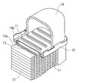
- FIG. 3 shows an assembled body for a heat exchanger in which the header plate 10 made of the multilayer clad material 20 for the heat exchanger is assembled.
- the header plate 10 has an air-side surface 10a made of a brazing material and a refrigerant-side surface 10b made of a sacrificial material, and many tubes 11 are fitted from the air-side surface 10a side. The tip of the tube 11 is projected beyond the surface 10b on the refrigerant side. Fins 12 are arranged between the tubes 11 on the air side and are in close contact with the tubes 11.
- a resin tank 14 is arranged on the refrigerant side of the header plate 10 so as to cover the protruding portion of the tube 11, and a rubber packing 13 seals between the resin tank 14 and the header plate 10.
- the tank may be made of an aluminum alloy material, and the aluminum alloy material of the present invention may be used as the material.
- the assembled body can be brazed by a conventional method. It should be noted that the present invention is not particularly limited in terms of heating conditions, atmosphere, type of flux, etc. in brazing.
- the fins 12 are brazed to the tube 11, the aluminum alloy brazing material of the header plate 10 is melted, the flow of the brazing is appropriately suppressed, and the fitting of the tube 11 is well performed. To be done.
- the refrigerant flows into each tube 11 through the inside of the resin tank 14. At this time, the header plate 10 in contact with the refrigerant exhibits good corrosion resistance regardless of whether it is alkaline or acidic due to the eutectic phase.
- the excellent multilayer clad material for heat exchanger is used for the header plate, but the present invention is not limited to the header plate.
- An aluminum alloy for a core material, an aluminum alloy for a sacrificial material, and an aluminum alloy for a brazing material having the compositions shown in Table 1 (the balance being Al and unavoidable impurities) were melted by a semi-continuous casting method.
- the obtained core material was selected at 550 to 600° C. for 5 to 10 hours and homogenized.
- the sacrificial material was not homogenized.
- the brazing material was homogenized at 400 to 500° C. for 1 to 10 hours.
- the sacrificial material is combined with one surface of the ingot of the core material and the brazing material on the other surface, and hot rolling is performed using a device of a hot rough rolling machine or a hot finish rolling machine.
- Brazing material 10%: 80%: Laminated with a clad ratio of 10%.
- cold rolling was performed to a thickness of 1 to 2 mm using a device of a cold finish rolling mill.
- heat treatment was performed at 300° C. to 450° C. for 1 to 10 hours in a batch annealing furnace in order to set the material quality to O.
- the multilayer clad material for a heat exchanger was processed by a press or the like so as to be used as a header plate, and, for example, after being assembled with an object to be brazed (Al—Mn tube material), they were joined by brazing.
- Al—Mn tube material Al—Mn tube material
- the temperature was raised from room temperature to 600° C., and after reaching 600° C., it was held for 5 minutes. Then, it was cooled to 300°C at 60°C/min.
- the obtained test materials were evaluated as follows and shown in Table 1 or Table 2.
- the speed was set to 0.5 mV/sec and the potential was swept by 1000 mV.
- the potential at the point connecting the respective tangents of the passive state holding current density and the point where the subsequent current flowed was selected.
- Potential differences ⁇ E A and ⁇ E B were calculated based on the obtained potentials, and those with ⁇ E A of 105 mV or more and ⁇ E B of 80 mV or more were evaluated as ⁇ , and the others were evaluated as x.
- the one having ⁇ E A of 120 mV or more and ⁇ E B of 100 mV or more was marked with ⁇ .
- Wax erosion rate A predetermined work strain (2 to 8%) was applied to the material before brazing, heat treatment equivalent to brazing was performed, and a cross section parallel to the rolling direction was mechanically polished. Polishing was performed using a coarse-grained polishing paper, and gradually polished to a mirror-finished state. The wax erosion rate was calculated from the following formula using a general-purpose optical microscope (magnification 50 times).
- E ⁇ t 0 ⁇ (l 1 +l 2 ) ⁇ t C ⁇ 100
- E wax erosion rate
- t 0 thickness of brazing sheet before heating
- t C minimum thickness of brazing sheet after heating which is not subjected to brazing corrosion
- l 1 , l 2 skin material thickness Satoshi
- ⁇ means that E is 10% or less
- x means that E is higher than 10%.
- the heat treatment equivalent to brazing is not particularly limited, but refers to performing heat treatment equivalent to brazing.
- the cross section parallel to the rolling direction of the brazed material was processed by using the ion milling method.
- the distribution state of the Al—Mn—Si compound in the sacrificial material was observed using a general-purpose scanning electron microscope.
- the equivalent circle diameter was calculated from the area of the obtained compound.
- the number of Al-Mn-Si-based compounds having a circle equivalent diameter of 0.1 ⁇ m to 0.5 ⁇ m of 1 to 100/ ⁇ m 2 is ⁇ or more, of which 80 to 100/ ⁇ m 2 is further included.
- Corrosion resistance for sacrificial material/packing; Corrosion resistance under packing No leakage after prescribed corrosion test (heat exchanger internal OY water circulation test).
- “O” indicates that there is no leakage from the gap between the sacrificial material and the packing in the corrosion test
- X indicates that leakage has occurred. ⁇ was given to the better ones.
Landscapes
- Engineering & Computer Science (AREA)
- Mechanical Engineering (AREA)
- Physics & Mathematics (AREA)
- Thermal Sciences (AREA)
- General Engineering & Computer Science (AREA)
- Chemical & Material Sciences (AREA)
- Materials Engineering (AREA)
- Metallurgy (AREA)
- Organic Chemistry (AREA)
- Laminated Bodies (AREA)
Abstract
L'invention concerne un matériau de gainage de couche externe pour un échangeur de chaleur qui présente la relation de différence de potentiel E3 < E1 < E2, où E1 est le potentiel d'un matériau de cœur, E3 est le potentiel de soudure eutectique d'un filet formé au niveau d'une partie de jonction d'un matériau à souder et du matériau de gainage de couche externe de l'échangeur de chaleur, et E2 est le potentiel du matériau à souder. En outre, la différence de potentiel ΔEA entre E3 et E2 est égale ou supérieure à 105 mV et la différence de potentiel ΔEB entre E3 et E1 est égale ou supérieure à 80 mV.
Applications Claiming Priority (2)
| Application Number | Priority Date | Filing Date | Title |
|---|---|---|---|
| JP2018232519A JP2020093279A (ja) | 2018-12-12 | 2018-12-12 | 根付部の耐食性に優れた熱交換器用多層クラッド材および熱交換器 |
| JP2018-232519 | 2018-12-12 |
Publications (1)
| Publication Number | Publication Date |
|---|---|
| WO2020121978A1 true WO2020121978A1 (fr) | 2020-06-18 |
Family
ID=71075764
Family Applications (1)
| Application Number | Title | Priority Date | Filing Date |
|---|---|---|---|
| PCT/JP2019/047912 Ceased WO2020121978A1 (fr) | 2018-12-12 | 2019-12-06 | Matériau de gainage de couche externe pour échangeur de chaleur ayant une résistance à la corrosion exceptionnelle dans la portion de racine, et échangeur de chaleur |
Country Status (2)
| Country | Link |
|---|---|
| JP (1) | JP2020093279A (fr) |
| WO (1) | WO2020121978A1 (fr) |
Citations (5)
| Publication number | Priority date | Publication date | Assignee | Title |
|---|---|---|---|---|
| JPH03124394A (ja) * | 1989-10-05 | 1991-05-27 | Furukawa Alum Co Ltd | Al製熱交換器の冷媒通路用ブレージングシート |
| JPH08143997A (ja) * | 1994-11-22 | 1996-06-04 | Furukawa Electric Co Ltd:The | 低温ろう付用アルミニウム合金フィン材およびブレージンクシート、並びにアルミニウム合金製熱交換器の製造方法およびアルミニウム合金製熱交換器 |
| JP2005515301A (ja) * | 2002-01-18 | 2005-05-26 | ペシネイ ロールド プロダクツ | 非再結晶化層ならびに関連する合金及び方法 |
| JP2011042853A (ja) * | 2009-08-24 | 2011-03-03 | Mitsubishi Alum Co Ltd | 耐食性および耐久性に優れるアルミニウム合金製熱交換器 |
| JP2018095925A (ja) * | 2016-12-14 | 2018-06-21 | 株式会社Uacj | アルミニウム合金ブレージングシート及びその製造方法 |
-
2018
- 2018-12-12 JP JP2018232519A patent/JP2020093279A/ja active Pending
-
2019
- 2019-12-06 WO PCT/JP2019/047912 patent/WO2020121978A1/fr not_active Ceased
Patent Citations (5)
| Publication number | Priority date | Publication date | Assignee | Title |
|---|---|---|---|---|
| JPH03124394A (ja) * | 1989-10-05 | 1991-05-27 | Furukawa Alum Co Ltd | Al製熱交換器の冷媒通路用ブレージングシート |
| JPH08143997A (ja) * | 1994-11-22 | 1996-06-04 | Furukawa Electric Co Ltd:The | 低温ろう付用アルミニウム合金フィン材およびブレージンクシート、並びにアルミニウム合金製熱交換器の製造方法およびアルミニウム合金製熱交換器 |
| JP2005515301A (ja) * | 2002-01-18 | 2005-05-26 | ペシネイ ロールド プロダクツ | 非再結晶化層ならびに関連する合金及び方法 |
| JP2011042853A (ja) * | 2009-08-24 | 2011-03-03 | Mitsubishi Alum Co Ltd | 耐食性および耐久性に優れるアルミニウム合金製熱交換器 |
| JP2018095925A (ja) * | 2016-12-14 | 2018-06-21 | 株式会社Uacj | アルミニウム合金ブレージングシート及びその製造方法 |
Also Published As
| Publication number | Publication date |
|---|---|
| JP2020093279A (ja) | 2020-06-18 |
Similar Documents
| Publication | Publication Date | Title |
|---|---|---|
| US8663817B2 (en) | Aluminum alloy strips for brazed heat exchanger tubes | |
| JP6452626B2 (ja) | アルミニウム合金クラッド材及びその製造方法、ならびに、当該アルミニウム合金クラッド材を用いた熱交換器及びその製造方法 | |
| JP6492017B2 (ja) | アルミニウム合金材及びその製造方法、並びにアルミニウム合金クラッド材及びその製造方法 | |
| JP3869846B2 (ja) | アルミニウム合金板および熱交換器 | |
| JP2011224656A (ja) | アルミニウム合金ブレージングシートおよび熱交換器 | |
| JP2011026681A (ja) | アルミニウム合金クラッド材 | |
| CN106164309B (zh) | 铝合金制钎焊板 | |
| JP6604699B2 (ja) | アルミニウム合金製クラッド材及びその製造方法 | |
| US10625379B2 (en) | Aluminum alloy cladding material, manufacturing method therefor, and heat exchanger using said aluminum alloy cladding material | |
| JP2018099726A (ja) | アルミニウム合金ブレージングシートのろう付方法 | |
| JP2017171996A (ja) | 熱交換器用アルミニウム合金材及びその製造方法、ならびに、熱交換器用アルミニウム合金クラッド材及びその製造方法 | |
| WO2018110320A1 (fr) | Tôle à brasage en alliage d'aluminium et son procédé de fabrication | |
| CN106715734B (zh) | 铝合金制钎焊板 | |
| JP6803827B2 (ja) | 熱交換器用アルミニウム合金材及び熱交換器 | |
| JP7244271B2 (ja) | 熱交換器用アルミニウム合金クラッド材及び熱交換器 | |
| JP2007327094A (ja) | ろう付け性に優れた熱交換器用高強度アルミニウム合金クラッド材 | |
| JP6415144B2 (ja) | アルミニウム合金クラッド材及び熱交換器 | |
| WO2020121978A1 (fr) | Matériau de gainage de couche externe pour échangeur de chaleur ayant une résistance à la corrosion exceptionnelle dans la portion de racine, et échangeur de chaleur | |
| JP6178483B1 (ja) | アルミニウム合金ブレージングシート | |
| JP4263160B2 (ja) | アルミニウム合金クラッド材並びにそれを用いた熱交換器用チューブ及び熱交換器 | |
| JP2018099725A (ja) | アルミニウム合金ブレージングシート | |
| JP6738666B2 (ja) | 大気環境における耐食性に優れるアルミニウム合金製熱交換器及びアルミニウム合金製熱交換器の製造方法 | |
| JP7520652B2 (ja) | 熱伝導性に優れたアルミニウム合金ベア材およびブレージングシート | |
| JP7555766B2 (ja) | 熱伝導性と耐エロージョン性に優れたアルミニウム合金ベア材およびアルミニウム合金ブレージングシート | |
| JP6526434B2 (ja) | アルミニウム合金フィン材 |
Legal Events
| Date | Code | Title | Description |
|---|---|---|---|
| 121 | Ep: the epo has been informed by wipo that ep was designated in this application |
Ref document number: 19897015 Country of ref document: EP Kind code of ref document: A1 |
|
| NENP | Non-entry into the national phase |
Ref country code: DE |
|
| 122 | Ep: pct application non-entry in european phase |
Ref document number: 19897015 Country of ref document: EP Kind code of ref document: A1 |