WO2020122023A1 - Élément d'affichage d'image de projection, vitre de pare-brise et système d'affichage tête haute - Google Patents
Élément d'affichage d'image de projection, vitre de pare-brise et système d'affichage tête haute Download PDFInfo
- Publication number
- WO2020122023A1 WO2020122023A1 PCT/JP2019/048114 JP2019048114W WO2020122023A1 WO 2020122023 A1 WO2020122023 A1 WO 2020122023A1 JP 2019048114 W JP2019048114 W JP 2019048114W WO 2020122023 A1 WO2020122023 A1 WO 2020122023A1
- Authority
- WO
- WIPO (PCT)
- Prior art keywords
- layer
- light
- liquid crystal
- polarization conversion
- image display
- Prior art date
- Legal status (The legal status is an assumption and is not a legal conclusion. Google has not performed a legal analysis and makes no representation as to the accuracy of the status listed.)
- Ceased
Links
Images


Classifications
-
- G—PHYSICS
- G02—OPTICS
- G02B—OPTICAL ELEMENTS, SYSTEMS OR APPARATUS
- G02B27/00—Optical systems or apparatus not provided for by any of the groups G02B1/00 - G02B26/00, G02B30/00
- G02B27/01—Head-up displays
- G02B27/0101—Head-up displays characterised by optical features
-
- B—PERFORMING OPERATIONS; TRANSPORTING
- B60—VEHICLES IN GENERAL
- B60K—ARRANGEMENT OR MOUNTING OF PROPULSION UNITS OR OF TRANSMISSIONS IN VEHICLES; ARRANGEMENT OR MOUNTING OF PLURAL DIVERSE PRIME-MOVERS IN VEHICLES; AUXILIARY DRIVES FOR VEHICLES; INSTRUMENTATION OR DASHBOARDS FOR VEHICLES; ARRANGEMENTS IN CONNECTION WITH COOLING, AIR INTAKE, GAS EXHAUST OR FUEL SUPPLY OF PROPULSION UNITS IN VEHICLES
- B60K35/00—Instruments specially adapted for vehicles; Arrangement of instruments in or on vehicles
- B60K35/20—Output arrangements, i.e. from vehicle to user, associated with vehicle functions or specially adapted therefor
- B60K35/21—Output arrangements, i.e. from vehicle to user, associated with vehicle functions or specially adapted therefor using visual output, e.g. blinking lights or matrix displays
- B60K35/22—Display screens
-
- B—PERFORMING OPERATIONS; TRANSPORTING
- B60—VEHICLES IN GENERAL
- B60K—ARRANGEMENT OR MOUNTING OF PROPULSION UNITS OR OF TRANSMISSIONS IN VEHICLES; ARRANGEMENT OR MOUNTING OF PLURAL DIVERSE PRIME-MOVERS IN VEHICLES; AUXILIARY DRIVES FOR VEHICLES; INSTRUMENTATION OR DASHBOARDS FOR VEHICLES; ARRANGEMENTS IN CONNECTION WITH COOLING, AIR INTAKE, GAS EXHAUST OR FUEL SUPPLY OF PROPULSION UNITS IN VEHICLES
- B60K35/00—Instruments specially adapted for vehicles; Arrangement of instruments in or on vehicles
- B60K35/20—Output arrangements, i.e. from vehicle to user, associated with vehicle functions or specially adapted therefor
- B60K35/21—Output arrangements, i.e. from vehicle to user, associated with vehicle functions or specially adapted therefor using visual output, e.g. blinking lights or matrix displays
- B60K35/23—Head-up displays [HUD]
- B60K35/231—Head-up displays [HUD] characterised by their arrangement or structure for integration into vehicles
-
- B—PERFORMING OPERATIONS; TRANSPORTING
- B60—VEHICLES IN GENERAL
- B60K—ARRANGEMENT OR MOUNTING OF PROPULSION UNITS OR OF TRANSMISSIONS IN VEHICLES; ARRANGEMENT OR MOUNTING OF PLURAL DIVERSE PRIME-MOVERS IN VEHICLES; AUXILIARY DRIVES FOR VEHICLES; INSTRUMENTATION OR DASHBOARDS FOR VEHICLES; ARRANGEMENTS IN CONNECTION WITH COOLING, AIR INTAKE, GAS EXHAUST OR FUEL SUPPLY OF PROPULSION UNITS IN VEHICLES
- B60K35/00—Instruments specially adapted for vehicles; Arrangement of instruments in or on vehicles
- B60K35/40—Instruments specially adapted for improving the visibility thereof to the user, e.g. fogging prevention or anti-reflection arrangements
- B60K35/425—Anti-reflection arrangements
-
- B—PERFORMING OPERATIONS; TRANSPORTING
- B60—VEHICLES IN GENERAL
- B60K—ARRANGEMENT OR MOUNTING OF PROPULSION UNITS OR OF TRANSMISSIONS IN VEHICLES; ARRANGEMENT OR MOUNTING OF PLURAL DIVERSE PRIME-MOVERS IN VEHICLES; AUXILIARY DRIVES FOR VEHICLES; INSTRUMENTATION OR DASHBOARDS FOR VEHICLES; ARRANGEMENTS IN CONNECTION WITH COOLING, AIR INTAKE, GAS EXHAUST OR FUEL SUPPLY OF PROPULSION UNITS IN VEHICLES
- B60K35/00—Instruments specially adapted for vehicles; Arrangement of instruments in or on vehicles
- B60K35/50—Instruments characterised by their means of attachment to or integration in the vehicle
-
- B—PERFORMING OPERATIONS; TRANSPORTING
- B60—VEHICLES IN GENERAL
- B60K—ARRANGEMENT OR MOUNTING OF PROPULSION UNITS OR OF TRANSMISSIONS IN VEHICLES; ARRANGEMENT OR MOUNTING OF PLURAL DIVERSE PRIME-MOVERS IN VEHICLES; AUXILIARY DRIVES FOR VEHICLES; INSTRUMENTATION OR DASHBOARDS FOR VEHICLES; ARRANGEMENTS IN CONNECTION WITH COOLING, AIR INTAKE, GAS EXHAUST OR FUEL SUPPLY OF PROPULSION UNITS IN VEHICLES
- B60K35/00—Instruments specially adapted for vehicles; Arrangement of instruments in or on vehicles
- B60K35/60—Instruments characterised by their location or relative disposition in or on vehicles
-
- B—PERFORMING OPERATIONS; TRANSPORTING
- B60—VEHICLES IN GENERAL
- B60K—ARRANGEMENT OR MOUNTING OF PROPULSION UNITS OR OF TRANSMISSIONS IN VEHICLES; ARRANGEMENT OR MOUNTING OF PLURAL DIVERSE PRIME-MOVERS IN VEHICLES; AUXILIARY DRIVES FOR VEHICLES; INSTRUMENTATION OR DASHBOARDS FOR VEHICLES; ARRANGEMENTS IN CONNECTION WITH COOLING, AIR INTAKE, GAS EXHAUST OR FUEL SUPPLY OF PROPULSION UNITS IN VEHICLES
- B60K35/00—Instruments specially adapted for vehicles; Arrangement of instruments in or on vehicles
- B60K35/80—Arrangements for controlling instruments
- B60K35/81—Arrangements for controlling instruments for controlling displays
-
- G—PHYSICS
- G02—OPTICS
- G02B—OPTICAL ELEMENTS, SYSTEMS OR APPARATUS
- G02B27/00—Optical systems or apparatus not provided for by any of the groups G02B1/00 - G02B26/00, G02B30/00
- G02B27/28—Optical systems or apparatus not provided for by any of the groups G02B1/00 - G02B26/00, G02B30/00 for polarising
- G02B27/286—Optical systems or apparatus not provided for by any of the groups G02B1/00 - G02B26/00, G02B30/00 for polarising for controlling or changing the state of polarisation, e.g. transforming one polarisation state into another
-
- G—PHYSICS
- G02—OPTICS
- G02B—OPTICAL ELEMENTS, SYSTEMS OR APPARATUS
- G02B5/00—Optical elements other than lenses
- G02B5/30—Polarising elements
- G02B5/3016—Polarising elements involving passive liquid crystal elements
-
- G—PHYSICS
- G02—OPTICS
- G02B—OPTICAL ELEMENTS, SYSTEMS OR APPARATUS
- G02B5/00—Optical elements other than lenses
- G02B5/30—Polarising elements
- G02B5/3083—Birefringent or phase retarding elements
-
- B—PERFORMING OPERATIONS; TRANSPORTING
- B60—VEHICLES IN GENERAL
- B60K—ARRANGEMENT OR MOUNTING OF PROPULSION UNITS OR OF TRANSMISSIONS IN VEHICLES; ARRANGEMENT OR MOUNTING OF PLURAL DIVERSE PRIME-MOVERS IN VEHICLES; AUXILIARY DRIVES FOR VEHICLES; INSTRUMENTATION OR DASHBOARDS FOR VEHICLES; ARRANGEMENTS IN CONNECTION WITH COOLING, AIR INTAKE, GAS EXHAUST OR FUEL SUPPLY OF PROPULSION UNITS IN VEHICLES
- B60K2360/00—Indexing scheme associated with groups B60K35/00 or B60K37/00 relating to details of instruments or dashboards
- B60K2360/20—Optical features of instruments
- B60K2360/25—Optical features of instruments using filters
-
- G—PHYSICS
- G02—OPTICS
- G02B—OPTICAL ELEMENTS, SYSTEMS OR APPARATUS
- G02B27/00—Optical systems or apparatus not provided for by any of the groups G02B1/00 - G02B26/00, G02B30/00
- G02B27/01—Head-up displays
- G02B27/0101—Head-up displays characterised by optical features
- G02B2027/0118—Head-up displays characterised by optical features comprising devices for improving the contrast of the display / brillance control visibility
Definitions
- the present invention relates to a projection image display member that can be used as a combiner for a head-up display system, a windshield glass having the projection image display member, and a head-up display system, and more particularly to a selective reflection layer that reflects light in a wavelength-selective manner. And a windshield glass and a head-up display system having the projection image display member.
- a head-up display or a head-up display system projects an image on a windshield of a vehicle or the like and provides a driver or the like with various information such as a map, traveling speed, and the state of the vehicle. ing.
- a driver or the like observes a virtual image of an image projected on the windshield and including the various information described above.
- the virtual image is formed on the front side outside the vehicle with respect to the windshield, usually 1000 mm or more from the windshield, on the front side, and on the outside world side with respect to the windshield.
- the driver can obtain the various information described above while looking at the outside world without moving the line of sight greatly. Therefore, when using the head-up display system, while obtaining various information, It is expected to drive safely.
- the windshield glass can form a head-up display system by forming a projection image display portion using a half mirror film.
- Various usable half mirror films have been proposed.
- a light reflection layer PRL-1 having a center reflection wavelength of 400 nm or more and less than 500 nm and a reflectance for normal light at the center reflection wavelength of 5% or more and 25% or less, and a center reflection of 500 nm or more and less than 600 nm are disclosed.
- a light-reflecting layer PRL-2 having a wavelength of 5% or more and 25% or less for ordinary light at the central reflection wavelength, and a reflectance of ordinary light at the central reflection wavelength having a central reflection wavelength of 600 nm or more and less than 700 nm.
- at least two or more light reflecting layers including one or more light reflecting layers and having different central reflection wavelengths are laminated and laminated.
- a light-reflecting film that reflects polarized light in the same direction is described.
- Patent Document 2 discloses a light-reflecting layer PRL-1 having a center reflection wavelength of 400 nm or more and less than 500 nm and a reflectance of 5% or more and 25% or less for normal light at the center reflection wavelength, and a plane shape of 500 nm.
- a light reflection layer PRL-2 having a central reflection wavelength of 600 nm or more and less than 600 nm and a reflectance for ordinary light of 5% or more and 25% or less at the central reflection wavelength, and a center having a central reflection wavelength of 600 nm or more and less than 700 nm in a planar shape.
- each light reflecting layer has a high reflectance with respect to the light emitted from the image display means converted into a specific polarized light, and is used for a head-up display. be able to.
- the head-up display has a high visible light transmittance and displays an image even if the driver wears polarized sunglasses. It is required to be visible. Since polarized sunglasses have a function of cutting s-polarized light, glare of reflected light from an oncoming vehicle's hood or puddle, which is a hindrance to driving, becomes invisible.
- the projection image is displayed with p-polarized light, and the image is visible because it is a member that reflects p-polarized light.
- the function of cutting the above-described glare of reflected light which is mainly composed of s-polarized light, is impaired.
- the cutting function is further impaired, which causes a problem of impeding operation.
- An object of the present invention is to provide a projection image display member, a windshield glass, and a head-up display system, which are excellent in the suitability of polarized sunglasses for incident light reflected by external light.
- a projection image display member having a first polarization conversion layer, at least one selective reflection layer, and a second polarization conversion layer in this order, and the first polarization conversion layer described above,
- the polarization conversion layer 2 is a layer in which a helical alignment structure of a liquid crystal compound is fixed, and the pitch number and film thickness of the above-mentioned helical alignment structure satisfy all the following relational expressions.
- a head-up display system that includes the windshield glass according to [4] and further includes a projector that emits p-polarized projection image light from the above-mentioned first polarization conversion layer side of the above-mentioned windshield glass.
- the present invention provides a windshield glass having a projection image display member. It is preferable that the projection image display member is arranged between the first glass plate and the second glass plate. An intermediate film is preferably provided on at least one of the first glass plate and the projection image display member and between the projection image display member and the second glass plate.
- the present invention is a head-up display system having a projection image display member, wherein the projection image display member is disposed between a first glass plate and a second glass plate, and a windshield.
- a head-up display system having a projector that irradiates p-polarized projection light on glass.
- the windshield glass is preferably provided with an intermediate film between at least one of the first glass plate and the projection image display member and between the projection image display member and the second glass plate.
- a projection image display member a windshield glass and a head-up display system, which are excellent in suitability for polarized sunglasses.
- FIG. 3 is a view of the laminated glass in Example 1 viewed from the side.
- FIG. 3 is a view of the laminated glass in Example 1 viewed from the first polarization conversion layer side.
- FIG. It is a figure which shows the measuring system in evaluation of brightness. It is a figure which shows the measuring system in evaluation of polarized sunglasses suitability.
- Angles such as “angle expressed by a specific numerical value”, “parallel”, “vertical” and “orthogonal” include an error range generally accepted in the corresponding technical field, unless otherwise specified. Further, “identical” includes an error range generally accepted in the relevant technical field, and “whole surface” etc. also includes an error range generally acceptable in the relevant technical field.
- the term “selective” for circularly polarized light means that the light amount of either the right circularly polarized light component or the left circularly polarized light component of light is larger than that of the other circularly polarized light component.
- the term “selective” means that the circular polarization degree of light is preferably 0.3 or more, more preferably 0.6 or more, and further preferably 0.8 or more. More preferably, it is substantially 1.0. Table In / (I R + I L)
- sense for circularly polarized light, it means either right-handed circularly polarized light or left-handed circularly polarized light.
- the sense of circularly polarized light is right circularly polarized when the tip of the electric field vector rotates clockwise with increasing time when viewed as if the light is traveling forward, and left when counterclockwise. It is defined as being circularly polarized.
- the term "sense” may be used for the twist direction of the spiral of cholesteric liquid crystal.
- the twist direction (sense) of the spiral of the cholesteric liquid crystal is right, right circularly polarized light is reflected and left circularly polarized light is transmitted, and when the sense is left, left circularly polarized light is reflected and right circularly polarized light is transmitted.
- the term "light” means visible light and natural light (non-polarized light).
- Visible light is, of electromagnetic waves, light having a wavelength that can be seen by the human eye, and usually shows light in the wavelength range of 380 to 780 nm.
- Non-visible light is light in the wavelength range of less than 380 nm or in the wavelength range of more than 780 nm.
- light in the wavelength range of 420 to 490 nm is blue (B) light
- light in the wavelength range of 495 to 570 nm is green (G) light.
- Light in the wavelength range of 620 to 750 nm is red (R) light.
- the "visible light transmittance” is the visible light transmittance of the A light source defined in JIS (Japanese Industrial Standard) R 3212:2015 (Test method for safety glass for automobiles). That is, the transmittance of each wavelength in the wavelength range of 380 to 780 nm is measured with a spectrophotometer using the A light source, and is obtained from the wavelength distribution and the wavelength interval of the CIE (International Commission on Illumination) light adaptation standard ratio visual sensitivity. It is the transmittance obtained by multiplying the transmittance at each wavelength by the obtained weighting coefficient and performing a weighted average.
- the term “reflected light” or “transmitted light” is used to include scattered light and diffracted light.
- the polarization state of each wavelength of light can be measured using a spectral radiance meter or a spectrum meter equipped with a circularly polarizing plate.
- the intensity of light measured through the right circularly polarizing plate corresponds to I R
- the intensity of light measured through the left circularly polarizing plate corresponds to I L.
- the measurement can be performed by attaching a circularly polarizing plate to the illuminometer or the optical spectrum meter.
- the ratio can be measured by attaching a right circularly polarized light transmitting plate, measuring the right circularly polarized light amount, and by attaching a left circularly polarized light transmitting plate and measuring the left circularly polarized light amount.
- ⁇ P-polarized light means polarized light that vibrates in a direction parallel to the plane of incidence of light.
- the incident surface means a surface that is perpendicular to the reflective surface (such as the windshield glass surface) and that includes incident light rays and reflected light rays.
- the plane of vibration of the electric field vector is parallel to the plane of incidence.
- the front phase difference is a value measured using an AxoScan manufactured by Axometrics.
- the measurement wavelength is 550 nm unless otherwise specified.
- the front phase difference may be a value measured by KOBRA 21ADH or WR (manufactured by Oji Scientific Instruments Co., Ltd.) with light having a wavelength within the visible light wavelength range incident in the normal direction of the film.
- the wavelength selection filter can be replaced manually or the measurement value can be converted by a program or the like for measurement.
- Projection image means an image based on the projection of light from the projector used, not the surrounding landscape such as the front.
- the projected image is observed as a virtual image that appears to the viewer in front of the projected image display portion of the windshield glass.
- “Screen image” means an image displayed on a drawing device of a projector or an image drawn on an intermediate image screen or the like by the drawing device.
- An image is a real image as opposed to a virtual image. Both the image and the projected image may be a monochromatic image, a multicolor image of two or more colors, or a full color image.
- the projected image display member means a half mirror that can reflect projected light carrying an image and can display the image carried by the projected light as a projected image by reflected light of the projected light.
- the projected image display member has visible light transparency.
- the visible light transmittance of the projected image display member is preferably 80% or more, more preferably 82% or more, and further preferably 84% or more.
- the projection image display member does not show substantial reflection in the wavelength range with high visibility. Specifically, when comparing a normal laminated glass and a laminated glass incorporating a projection image display member with respect to light from the normal direction, substantially equal reflection is shown at a wavelength of about 550 nm. Is preferred. More preferably, it is preferable that substantially the same reflection is exhibited in the visible light wavelength range of 490 to 620 nm.
- “Substantially equivalent reflection” means, for example, reflection of natural light (non-polarized light) at a target wavelength measured from a normal direction with a spectrophotometer such as a spectrophotometer "V-670" manufactured by JASCO Corporation. It means that the difference in the rates is 10% or less.
- the difference in reflectance is preferably 5% or less, more preferably 3% or less, further preferably 2% or less, and particularly preferably 1% or less. .. Visible light transmission that meets the standard of vehicle windshield glass even when combined with glass with low visible light transmittance to form laminated glass by showing substantially equivalent reflection in the wavelength range with high visibility The rate can be realized.
- the projection image display member may be a thin film, sheet, or the like. Before being used for windshield glass, the projection image display member may be in a roll shape or the like as a thin film.
- the projection image display member may have a function as a half mirror for at least a part of the projected light, for example, as a half mirror for light in the entire visible light range. It doesn't need to be functional. Further, the projection image display member may have a function as the above-mentioned half mirror for light having all incident angles, but has a function as described above for light having at least some incident angles. All you have to do is do it.
- the projection image display member has a first polarization conversion layer, a selective reflection layer, and a second polarization conversion layer. If the projection image display member has a first polarization conversion layer, a selective reflection layer, and a second polarization conversion layer, in addition to this, a retardation layer, a support, an alignment layer, an adhesive layer, etc. It may be configured to include. Hereinafter, the projected image display member will be described more specifically.
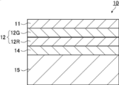
- FIG. 1 is a schematic diagram showing an example of a projection image display member according to an embodiment of the present invention.
- the first polarization conversion layer 14, the selective reflection layer 12, and the second polarization conversion layer 11 are laminated in this order on the support 15.
- the projection image display member 10 may be any structure as long as it has at least the first polarization conversion layer 14, the selective reflection layer 12, and the second polarization conversion layer 11, and the support 15 may be omitted.
- the selective reflection layer is a layer that selectively reflects light as described above.
- the selective reflection layer preferably exhibits selective reflection in a part of the visible light wavelength range.
- the selective reflection layer may reflect light for displaying a projected image.
- the selective reflection layer may have a configuration having a selective reflection layer corresponding to each wavelength range.
- the selective reflection layer 12 shown in FIG. 1 includes a first selective reflection layer 12G that selectively reflects light having a wavelength of 500 to 650 nm and a second selective reflection layer 12G that selectively reflects light having a wavelength of 650 to 900 nm.
- the selective reflection layer 12R and the first selective reflection layer 12G and the second selective reflection layer 12R are stacked in this order on the first polarization conversion layer 14.
- the selective reflection layer is preferably a polarization reflection layer.
- the polarization reflection layer is a layer that reflects linearly polarized light, circularly polarized light, or elliptically polarized light.
- the polarization reflection layer is preferably a circular polarization reflection layer or a linear polarization reflection layer.
- the circularly polarized light reflection layer is a layer that reflects circularly polarized light of either sense and transmits the other at the center wavelength of selective reflection.
- the linearly polarized light reflection layer is a layer that reflects linearly polarized light in one polarization direction and transmits linearly polarized light in a polarization direction orthogonal to the above-described polarization direction at the central wavelength of selective reflection.
- the polarized reflection layer can transmit polarized light that is not reflected, and can also transmit a part of light even in the wavelength range in which the selective reflection layer reflects. Therefore, it is preferable that the tint of the light transmitted through the projection image display member is not easily deteriorated and the visible light transmittance is not easily lowered.
- the selective reflection layer preferably includes a cholesteric liquid crystal layer, and may have a configuration including two or more cholesteric liquid crystal layers.
- the central wavelength of the selective reflection layer is preferably 500 to 650 nm and 650 to 900 nm, more preferably 530 to 630 nm and 670 to 850 nm, and more preferably 550 from the viewpoint of tint and visible light transmittance. More preferably, they are in the range of -610 nm and 680-800 nm.
- the projection image display member When the selective reflection layer includes a cholesteric liquid crystal layer, the projection image display member preferably includes a retardation layer.
- a retardation layer By using the retardation layer in combination with the cholesteric liquid crystal layer, a clear projected image can be displayed.
- the central wavelength of reflection of the cholesteric liquid crystal layer shifts to the short wave side with respect to oblique light.
- the shift of the center wavelength of the reflection to the short wave side is called blue shift.
- a blue shift occurs in the cholesteric liquid crystal layer due to a decrease in the optical path length difference between the layers due to optical interference. Therefore, when observed from an oblique direction, blue shift occurs. Therefore, when the selective reflection layer is composed of a cholesteric liquid crystal layer, it is desirable to shift the central reflection wavelength on the front side of the selective reflection layer to the long wave side by previously correcting the shift of the central wavelength of reflection to the short wave side.
- the center wavelength may be shifted.
- the wavelength range of the selective reflection layer 12 is set in consideration of the blue shift.
- the cholesteric liquid crystal layer means a layer in which a cholesteric liquid crystal phase is fixed.
- the cholesteric liquid crystal layer only needs to be a layer in which the orientation of the liquid crystal compound in the cholesteric liquid crystal phase is maintained.
- the polymerizable liquid crystal compound is placed in the orientation state of the cholesteric liquid crystal phase and then irradiated with ultraviolet rays.
- the layer may be a layer that is polymerized and hardened by heating or the like to form a layer having no fluidity, and at the same time, is changed to a state in which the orientation form is not changed by an external field or an external force.
- the optical properties of the cholesteric liquid crystal phase are retained in the layer, and the liquid crystal compound in the layer may no longer exhibit liquid crystallinity.
- the polymerizable liquid crystal compound may have a high molecular weight due to a curing reaction and may lose the liquid crystallinity.
- the cholesteric liquid crystal phase exhibits circularly polarized light selective reflection that selectively reflects the circularly polarized light of either the right circularly polarized light or the left circularly polarized light and transmits the circularly polarized light of the other sense.
- a film including a layer in which a cholesteric liquid crystal phase exhibiting circularly polarized light selective reflectivity is fixed many films formed from a composition containing a polymerizable liquid crystal compound have been conventionally known. Can refer to technology.
- the selective reflection center wavelength and the half value width of the cholesteric liquid crystal layer can be obtained as follows.
- a peak of transmittance decrease was found in the selective reflection band. Seen.
- the wavelength value on the short wavelength side is ⁇ l (nm) and the wavelength value on the long wavelength side is Is defined as ⁇ h (nm)
- the central wavelength ⁇ of selective reflection and the half width ⁇ can be expressed by the following formulas.
- a head-up display system to be described later, by using light so that the light is obliquely incident on the windshield glass, it is possible to reduce the reflectance on the surface of the glass plate on the projection light incident side. At this time, light also enters the cholesteric liquid crystal layer obliquely.
- light incident in the air with a refractive index of 1 at an angle of 45° to 70° with respect to the normal line of the projected image display portion has an angle of about 26° to 36° for a cholesteric liquid crystal layer having a refractive index of about 1.61.
- the reflected wavelength shifts to the short wavelength side.
- the cholesteric liquid crystal layer having a central wavelength of selective reflection in the range of 650 to 780 nm can reflect projection light in the range of 520 to 695 nm. Since such a wavelength range has a high luminosity factor, the contribution to the brightness of the projected image is high, and as a result, a projected image with high brightness can be realized.
- the pitch of the cholesteric liquid crystal phase depends on the type of chiral agent used with the polymerizable liquid crystal compound or the concentration added, the desired pitch can be obtained by adjusting these.
- the method of measuring the sense and pitch of the spiral use the method described in “Introduction to Liquid Crystal Chemistry”, edited by The Liquid Crystal Society of Japan, Sigma Publishing 2007, page 46, and “Liquid Crystal Handbook”, Liquid Crystal Handbook Editorial Committee Maruzen, page 196 be able to.
- the cholesteric liquid crystal layers are arranged in order from the one having the shorter central wavelength of selective reflection when viewed from the viewing side (inside the vehicle).
- each cholesteric liquid crystal layer a cholesteric liquid crystal layer whose sense of spiral is either right or left is used.
- the sense of the reflected circularly polarized light of the cholesteric liquid crystal layer matches the sense of the spiral.
- the spiral senses of the cholesteric liquid crystal layer having different selective reflection central wavelengths may be the same or different. However, it is preferable that the plurality of cholesteric liquid crystal layers have the same twist direction.
- the projection image display member does not include cholesteric liquid crystal layers having different spiral senses as a cholesteric liquid crystal layer that exhibits selective reflection in the same or overlapping wavelength ranges. This is to prevent the transmittance in a specific wavelength range from decreasing to less than 50%, for example.
- the ⁇ n can be adjusted by adjusting the type or mixing ratio of the polymerizable liquid crystal compound or controlling the temperature at the time of fixing the alignment.
- a plurality of cholesteric liquid crystal layers having the same pitch P and the same spiral sense may be laminated. By stacking cholesteric liquid crystal layers having the same pitch P and the same spiral sense, circularly polarized light selectivity can be increased at a specific wavelength.
- the selective reflection layer 12 preferably has a cholesteric liquid crystal layer having a reflection wavelength band within a wavelength range of 540 to 850 nm and a half width of 150 nm or more.
- the half-value width of the selective reflection layer 12 is 150 nm or more, the cholesteric liquid crystal layer having the central wavelength of the selective reflection becomes the broadband selective reflection layer, and the brightness of the image can be increased.
- a separately prepared cholesteric liquid crystal layer may be laminated with an adhesive or the like, and the polymerizable liquid crystal is directly formed on the surface of the previous cholesteric liquid crystal layer formed by the method described below.
- the liquid crystal composition containing a compound or the like may be applied and the steps of aligning and fixing may be repeated, but the latter is preferred.
- the orientation direction of the liquid crystal molecules on the air interface side of the previously formed cholesteric liquid crystal layer and the cholesteric liquid crystal layer formed thereon This is because the orientations of the liquid crystal molecules on the lower side are the same, and the polarization characteristics of the laminate of the cholesteric liquid crystal layer are good. In addition, interference unevenness that may occur due to uneven thickness of the adhesive layer is not observed.
- the thickness of the cholesteric liquid crystal layer is preferably 0.2 to 10 ⁇ m, more preferably 0.3 to 8.0 ⁇ m, and further preferably 0.4 to 6.0 ⁇ m.
- the total thickness of the cholesteric liquid crystal layer in the projection image display member is preferably 1.0 to 30 ⁇ m, more preferably 1.5 to 25 ⁇ m, and further preferably 2.0 to 20 ⁇ m. preferable.
- the visible light transmittance can be maintained high without reducing the thickness of the cholesteric liquid crystal layer.
- the material used for forming the cholesteric liquid crystal layer include a liquid crystal composition containing a polymerizable liquid crystal compound and a chiral agent (optically active compound). If necessary, the liquid crystal composition described above, which is further mixed with a surfactant or a polymerization initiator and dissolved in a solvent or the like, is applied to a support, an alignment layer, a cholesteric liquid crystal layer as a lower layer, and the like, and after cholesteric alignment aging.
- the cholesteric liquid crystal layer can be formed by fixing the liquid crystal composition by curing.
- the polymerizable liquid crystal compound may be a rod-shaped liquid crystal compound or a discotic liquid crystal compound, but is preferably a rod-shaped liquid crystal compound.
- An example of the rod-shaped polymerizable liquid crystal compound forming the cholesteric liquid crystal layer is a rod-shaped nematic liquid crystal compound.
- rod-shaped nematic liquid crystal compounds examples include azomethines, azoxys, cyanobiphenyls, cyanophenyl esters, benzoic acid esters, cyclohexanecarboxylic acid phenyl esters, cyanophenylcyclohexanes, cyano-substituted phenylpyrimidines, and alkoxy-substituted phenylpyrimidines.
- Phenyldioxane, tolan, and alkenylcyclohexylbenzonitrile are preferably used. Not only a low molecular weight liquid crystal compound but also a high molecular weight liquid crystal compound can be used.
- the polymerizable liquid crystal compound is obtained by introducing a polymerizable group into the liquid crystal compound.
- the polymerizable group include an unsaturated polymerizable group, an epoxy group, and an aziridinyl group, the unsaturated polymerizable group is preferable, and the ethylenically unsaturated polymerizable group is particularly preferable.
- the polymerizable group can be introduced into the molecule of the liquid crystal compound by various methods.
- the number of polymerizable groups contained in the polymerizable liquid crystal compound is preferably 1 to 6, and more preferably 1 to 3 in one molecule. Examples of the polymerizable liquid crystal compound are described in Makromol. Chem.
- the addition amount of the polymerizable liquid crystal compound in the liquid crystal composition is preferably 80 to 99.9 mass% with respect to the solid content mass (mass excluding the solvent) of the liquid crystal composition, and 85 to 99. It is more preferably 0.5% by mass, and particularly preferably 90 to 99% by mass.
- the first selective reflection layer 12G may have a low ⁇ n.
- the low ⁇ n first selective reflection layer 12G can be formed using a low ⁇ n polymerizable liquid crystal compound.
- the low ⁇ n polymerizable liquid crystal compound will be specifically described.
- a narrow band selective reflection layer can be obtained by forming a cholesteric liquid crystal phase by using a low ⁇ n polymerizable liquid crystal compound and fixing it to a film.
- the low ⁇ n polymerizable liquid crystal compound include compounds described in WO2015/115390, WO2015/147243, WO2016/035873, JP-A-2015-163596, and JP-A-2016-53149.
- the description of WO2016/047648 can also be referred to for the liquid crystal composition which provides the selective reflection layer having a narrow half width.
- liquid crystal compound is a polymerizable compound represented by the following formula (I) described in WO2016/047648.
- A represents a phenylene group which may have a substituent or a trans-1,4-cyclohexylene group which may have a substituent
- m is Represents an integer of 3 to 12
- Sp 1 and Sp 2 are each independently a single bond, a straight-chain or branched alkylene group having 1 to 20 carbon atoms, and a straight-chain or branched alkylene group having 1 to 20 carbon atoms.
- One or more —CH 2 — is —O—, —S—, —NH—, —N(CH 3 )—, —C( ⁇ O)—, —OC( ⁇ O)—, or —
- the phenylene group in formula (I) is preferably a 1,4-phenylene group.
- the substituents that may be “may have a substituent” are not particularly limited, and examples thereof include an alkyl group, a cycloalkyl group, an alkoxy group and an alkyl ether.
- the substituent include a group, an amide group, an amino group, a halogen atom, and a substituent selected from the group consisting of a combination of two or more of the above substituents.
- the phenylene group and trans-1,4-cyclohexylene group may have 1 to 4 substituents. When it has two or more substituents, the two or more substituents may be the same or different from each other.
- the alkyl group may be linear or branched.
- the alkyl group preferably has 1 to 30 carbon atoms, more preferably has 1 to 10 carbon atoms, and further preferably has 1 to 6 carbon atoms.
- Examples of the alkyl group include, for example, methyl group, ethyl group, n-propyl group, isopropyl group, n-butyl group, isobutyl group, sec-butyl group, tert-butyl group, n-pentyl group, isopentyl group, neopentyl group.
- Examples thereof include a group, a 1,1-dimethylpropyl group, an n-hexyl group, an isohexyl group, a linear or branched heptyl group, an octyl group, a nonyl group, a decyl group, an undecyl group, and a dodecyl group.
- the above description regarding the alkyl group is the same for the alkoxy group containing an alkyl group.
- specific examples of the alkylene group when referred to as an alkylene group include a divalent group obtained by removing one arbitrary hydrogen atom from each of the above examples of the alkyl group.
- Examples of the halogen atom include a fluorine atom, a chlorine atom, a bromine atom and an iodine atom.
- the cycloalkyl group preferably has 3 to 20 carbon atoms, more preferably has 5 or more carbon atoms, preferably has 10 or less carbon atoms, more preferably has 8 or less carbon atoms, and further preferably has 6 or less carbon atoms.
- Examples of the cycloalkyl group include a cyclopropyl group, a cyclobutyl group, a cyclopentyl group, a cyclohexyl group, a cycloheptyl group, and a cyclooctyl group.
- X 3 represents a single bond, —O—, —S—, or —N(Sp 4 —Q 4 )—, or is a nitrogen atom forming a ring structure together with Q 3 and Sp 3. Show.
- Sp 3 and Sp 4 are each independently one or more of a single bond, a straight-chain or branched alkylene group having 1 to 20 carbon atoms, and a straight-chain or branched alkylene group having 1 to 20 carbon atoms.
- a linking group selected from the group consisting of substituted groups is shown.
- one or more —CH 2 — is —O—, —S—, —NH—, —N(CH 3 )—, —C( ⁇ O)—, —OC( ⁇ O)
- Specific examples of the group substituted with — or —C( ⁇ O)O— include a tetrahydrofuranyl group, a pyrrolidinyl group, an imidazolidinyl group, a pyrazolidinyl group, a piperidyl group, a piperazinyl group, and a morpholinyl group. ..
- the substitution position is not particularly limited. Of these, a tetrahydrofuranyl group is preferable, and a 2-tetrahydrofuranyl group is particularly preferable.
- the m-1 L's may be the same or different from each other.
- Sp 1 and Sp 2 are each independently one or more of a single bond, a straight-chain or branched alkylene group having 1 to 20 carbon atoms, and a straight-chain or branched alkylene group having 1 to 20 carbon atoms.
- a linking group selected from the group consisting of substituted groups is shown.
- Sp 1 and Sp 2 are each independently a carbon atom having a linking group selected from the group consisting of —O—, —OC( ⁇ O)—, and —C( ⁇ O)O— at both ends.
- 1 or a combination of 2 or more is preferably a linking group, and a linear alkylene group having 1 to 10 carbon atoms in which —O— is bonded to both ends is preferable.
- Q 1 and Q 2 each independently represent a hydrogen atom or a polymerizable group selected from the group consisting of the groups represented by the above formulas Q-1 to Q-5, provided that Q 1 and Q 2 are One of them represents a polymerizable group.
- the polymerizable group an acryloyl group (formula Q-1) or a methacryloyl group (formula Q-2) is preferable.
- m represents an integer of 3 to 12, preferably an integer of 3 to 9, more preferably an integer of 3 to 7, and further preferably an integer of 3 to 5.
- the polymerizable compound represented by the formula (I) has, as A, at least one optionally substituted phenylene group and optionally substituted trans-1,4-cyclohexylene group. It is preferable to include at least one.
- the polymerizable compound represented by the formula (I) preferably contains, as A, 1 to 4 trans-1,4-cyclohexylene groups optionally having a substituent, and preferably 1 to 3 trans-1 ,4-cyclohexylene groups which may have a substituent. Is more preferable, and it is still more preferable to include 2 or 3.
- the polymerizable compound represented by the formula (I) preferably contains, as A, at least one phenylene group which may have a substituent, more preferably 1 to 4 and more preferably 1 to 4 It is more preferable to include three, and it is particularly preferable to include two or three.
- the number obtained by dividing the number of trans-1,4-cyclohexylene groups represented by A by m is mc
- polymerizable compound represented by formula (I) examples include the compounds described in paragraphs 0051 to 0058 of WO2016/047648, JP-A Nos. 2013-112631 and 2010-70543, Examples thereof include compounds described in Japanese Patent No. 4725516, WO2015/115390, WO2015/147243, WO2016/035873, JP-A-2015-163596, and JP-A-2016-53149.
- the chiral agent has a function of inducing a helical structure of the cholesteric liquid crystal phase.
- the chiral compound may be selected according to the purpose because the sense of the spiral or the helical pitch induced by the compound differs.
- the chiral agent is not particularly limited, and known compounds can be used.
- Examples of the chiral agent include a liquid crystal device handbook (Chapter 3, Section 4-3, TN, chiral agent for STN, page 199, Japan Society for the Promotion of Science, 142nd Committee, 1989), JP-A-2003-287623, The compounds described in JP-A-2002-302487, JP-A-2002-80478, JP-A-2002-80851, JP-A-2010-181852 or JP-A-2014-034581 are mentioned.
- the chiral agent generally contains an asymmetric carbon atom, but an axially asymmetric compound or a planar asymmetric compound containing no asymmetric carbon atom can also be used as the chiral agent.
- Examples of the axially chiral compound or the planar chiral compound include binaphthyl, helicene, paracyclophane, and derivatives thereof.
- the chiral agent may have a polymerizable group. When both the chiral agent and the liquid crystal compound have a polymerizable group, a repeating unit derived from the polymerizable liquid crystal compound and a chiral agent are generated by a polymerization reaction between the polymerizable chiral agent and the polymerizable liquid crystal compound.
- Polymers having repeating units can be formed.
- the polymerizable group contained in the polymerizable chiral agent is preferably the same group as the polymerizable group contained in the polymerizable liquid crystal compound. Therefore, the polymerizable group of the chiral agent is also preferably an unsaturated polymerizable group, an epoxy group or an aziridinyl group, more preferably an unsaturated polymerizable group, and an ethylenically unsaturated polymerizable group. Particularly preferred. Further, the chiral agent may be a liquid crystal compound.
- an isosorbide derivative As the chiral agent, an isosorbide derivative, an isomannide derivative, or a binaphthyl derivative can be preferably used.
- an isosorbide derivative a commercially available product such as LC756 manufactured by BASF may be used.
- the content of the chiral agent in the liquid crystal composition is preferably 0.01 mol% to 200 mol% of the amount of the polymerizable liquid crystal compound, and more preferably 1 mol% to 30 mol %.
- the liquid crystal composition preferably contains a polymerization initiator.
- the polymerization initiator used is preferably a photopolymerization initiator capable of initiating the polymerization reaction by irradiation with ultraviolet rays.
- the photopolymerization initiator include ⁇ -carbonyl compounds (described in US Pat. No. 2,366,661 and US Pat. No. 2,367,670), acyloin ethers (US Pat. No. 2,448,828), ⁇ -hydrocarbons. Of substituted aromatic acyloin compounds (described in US Pat. No.
- JP-B-63-40799 JP-B-5-29234, JP-A-10-95788, JP-A-10-29997, JP-A-2001-233842, JP-A-2000-80068, JP-A-2006-342166, and JP-A-2006-342166.
- oxadiazole compounds described in US Pat. No. 4,212,970
- an acylphosphine oxide compound or an oxime compound as the polymerization initiator.
- acylphosphine oxide compound for example, IRGACURE 810 (compound name: bis(2,4,6-trimethylbenzoyl)-phenylphosphine oxide) commercially available from BASF Japan Ltd. can be used.
- oxime compound IRGACURE OXE01 (manufactured by BASF), IRGACURE OXE02 (manufactured by BASF), TR-PBG-304 (manufactured by Changzhou Power Electronics Co., Ltd.), ADEKA ARKUL'S NCI-831, ADEKA ARKRUZ NCI-930.
- the polymerization initiator may be used alone or in combination of two or more.
- the content of the photopolymerization initiator in the liquid crystal composition is preferably 0.1% by mass to 20% by mass, and more preferably 0.5% by mass to 5% by mass, with respect to the content of the polymerizable liquid crystal compound. Is more preferable.
- the liquid crystal composition may optionally contain a crosslinking agent in order to improve the film strength after curing and the durability.
- a crosslinking agent one that can be cured by ultraviolet rays, heat, moisture or the like can be preferably used.
- the cross-linking agent is not particularly limited and may be appropriately selected depending on the intended purpose. Examples thereof include polyfunctional acrylate compounds such as trimethylolpropane tri(meth)acrylate and pentaerythritol tri(meth)acrylate; glycidyl (meth).
- Epoxy compounds such as acrylates and ethylene glycol diglycidyl ether; aziridine compounds such as 2,2-bishydroxymethylbutanol-tris[3-(1-aziridinyl)propionate] and 4,4-bis(ethyleneiminocarbonylamino)diphenylmethane; Isocyanate compounds such as hexamethylene diisocyanate and biuret type isocyanate; polyoxazoline compounds having an oxazoline group in the side chain; alkoxysilane compounds such as vinyltrimethoxysilane and N-(2-aminoethyl)3-aminopropyltrimethoxysilane Can be mentioned.
- a known catalyst can be used depending on the reactivity of the cross-linking agent, and the productivity can be improved in addition to the improvement of the film strength and durability. These may be used alone or in combination of two or more.
- the content of the crosslinking agent is preferably 3% by mass to 20% by mass, more preferably 5% by mass to 15% by mass.
- orientation control agent An alignment control agent that contributes to the stable or rapid formation of a cholesteric liquid crystal layer having a planar alignment may be added to the liquid crystal composition.
- the orientation control agent include fluorine (meth)acrylate polymers described in paragraphs [0018] to [0043] of JP2007-272185A, and paragraphs [0031] to [0034] of JP2012-203237A. ] And the like, compounds represented by formulas (I) to (IV), compounds described in JP-A-2013-113913, and the like.
- the orientation control agent one kind may be used alone, or two or more kinds may be used in combination.
- the addition amount of the orientation control agent in the liquid crystal composition is preferably 0.01% by mass to 10% by mass, more preferably 0.01% by mass to 5% by mass, based on the total mass of the polymerizable liquid crystal compound. It is particularly preferably from 0.02% by mass to 1% by mass.
- the liquid crystal composition may contain at least one selected from a surfactant for adjusting the surface tension of the coating film to make the thickness uniform, and various additives such as a polymerizable monomer.
- a polymerization inhibitor, an antioxidant, an ultraviolet absorber, a light stabilizer, a coloring material, and metal oxide fine particles may be added within a range that does not deteriorate the optical performance. Can be added.
- the cholesteric liquid crystal layer is a support, an alignment layer, or a liquid crystal composition prepared by dissolving a polymerizable liquid crystal compound, a polymerization initiator, and a chiral agent, a surfactant, etc., which are added if necessary, in a solvent.
- the laminated film composed of a plurality of cholesteric liquid crystal layers can be formed by repeating the above-described manufacturing process of the cholesteric liquid crystal layer.
- the solvent used for preparing the liquid crystal composition is not particularly limited and may be appropriately selected depending on the intended purpose, but organic solvents are preferably used.
- the organic solvent is not particularly limited and may be appropriately selected depending on the intended purpose. Examples thereof include ketones, alkyl halides, amides, sulfoxides, heterocyclic compounds, hydrocarbons, esters, and ethers. And the like. These may be used alone or in combination of two or more. Among these, ketones are particularly preferable in consideration of environmental load.
- the alignment layer, the coating method of the liquid crystal composition to the cholesteric liquid crystal layer to be the lower layer is not particularly limited and can be appropriately selected depending on the purpose, for example, a wire bar coating method, a curtain coating method, Examples thereof include extrusion coating method, direct gravure coating method, reverse gravure coating method, die coating method, spin coating method, dip coating method, spray coating method, and slide coating method. It can also be carried out by transferring a liquid crystal composition separately coated on a support. By heating the applied liquid crystal composition, the liquid crystal molecules are aligned. The heating temperature is preferably 200°C or lower, more preferably 130°C or lower. By this alignment treatment, an optical thin film in which the polymerizable liquid crystal compound is twisted and aligned so as to have a spiral axis in a direction substantially perpendicular to the film surface is obtained.
- the liquid crystal composition can be cured by further polymerizing the aligned liquid crystal compound.
- the polymerization may be either thermal polymerization or photopolymerization utilizing light irradiation, but photopolymerization is preferred. It is preferable to use ultraviolet rays for the light irradiation.
- the irradiation energy is preferably 20mJ / cm 2 ⁇ 50J / cm 2, 100mJ / cm 2 ⁇ 1,500mJ / cm 2 is more preferable.
- light irradiation may be carried out under heating conditions or under a nitrogen atmosphere.
- the irradiation ultraviolet wavelength is preferably 350 to 430 nm.
- the polymerization reaction rate is preferably high, preferably 70% or more, and more preferably 80% or more.
- the polymerization reaction rate can be determined by measuring the consumption rate of the polymerizable functional group by measuring the infrared absorption spectrum.
- Linear polarized light reflection layer As the selective reflection layer, a linearly polarized light reflection layer may be used as long as it has the same reflectance characteristic as the selective reflection layer described above.
- Examples of the linearly polarized light reflection layer include a polarizer in which thin films having different refractive index anisotropies are laminated. Such a polarizer has a high visible light transmittance similar to that of the cholesteric liquid crystal layer, and is capable of reflecting projection light obliquely incident when used in a head-up display system at a wavelength having high visibility.
- a polarizer in which thin films having different refractive index anisotropies are laminated, for example, those described in Japanese Patent Publication No. 9-506837 can be used.
- a polarizer can be formed using a wide variety of materials when processed under the conditions selected to obtain the refractive index relationship.
- one of the first materials has a different index of refraction than the second material in the chosen direction.
- This difference in index of refraction can be achieved in a variety of ways, including stretching, extrusion, or coating during or after film formation.
- the two materials have similar rheological properties (eg melt viscosity) so that they can be coextruded.
- a commercially available product can be used as the polarizer in which thin films having different refractive index anisotropies are laminated.
- a commercially available product may be used which is a laminate of a reflective polarizing plate and a temporary support.
- Examples of commercially available products include DBEF (registered trademark) (manufactured by 3M Company), and commercially available optical films sold as APF (Advanced Polarizing Film (manufactured by 3M Company)).
- the thickness of the reflective polarizing plate is preferably in the range of 2.0 to 50 ⁇ m, more preferably 8.0 to 30 ⁇ m.
- the difference between the first maximum refractive index and the second refractive index is preferably 0.1 or more, and the number of layers is preferably 4 to 20.
- polarization conversion layer As the polarization conversion layer, a first polarization conversion layer, at least one selective reflection layer, and a second polarization conversion layer are provided in this order.
- the first polarization conversion layer 14, the selective reflection layer 12, and the second polarization conversion layer 11 may be provided in this order from the viewing side as shown in FIG. ..
- the first polarization conversion layer 14 and the second polarization conversion layer 11 satisfy all of the following relational expressions (i) to (v).
- a polarization conversion layer in the projection image display member, it is possible to improve suitability for polarized sunglasses that cuts s-polarized light, which is a main component of glare of reflected light from an oncoming vehicle hood or a puddle. Further, a double image can be suppressed, and in particular, a double image when p-polarized light is incident to form a projected image can be excellently suppressed.
- the polarization conversion layer has a spiral structure of a cholesteric liquid crystal phase, and the visible light having a shorter wavelength than the reflection peak wavelength in the infrared region is used.
- the polarization conversion layer since it exhibits optical rotatory power and birefringence, it is possible to control polarized light in the visible region.
- the s-polarized light incident from the outside of the glass has a large change in polarization due to the film configuration including the retardation layer. Therefore, if the pitch number and the film thickness of the polarization conversion layer are controlled so that the polarization conversion layer can optically compensate, the suitability for polarized sunglasses is improved. it can.
- the first polarization conversion layer and the second polarization conversion layer perform optical compensation so that the s-polarized light incident from the outside of the glass is transmitted through the glass while maintaining the s-polarized light.
- the reason why the performance of cutting s-polarized light that is incident from the oblique direction on the outside of the glass can be improved is that the ⁇ /4 phase difference layer that is generally used for polarization conversion is light that is incident on the slow axis.
- the effect of polarization conversion varies greatly depending on the angle, whereas in the polarization conversion layer with the spiral structure of the cholesteric liquid crystal phase, the direction of the liquid crystal is not uniquely determined, and the angle of incident light changes. It is presumed that the effect of polarization conversion is unlikely to change.
- the reason why the double image can be further suppressed by providing the polarization conversion layer is that light with a wavelength that is not in the selective reflection band of the cholesteric liquid crystal layer undergoes polarization conversion by the cholesteric liquid crystal layer and is reflected on the back surface of the windshield glass. It is presumed that it is possible to suppress the double image based on the above.
- the polarization conversion layer is a layer in which the helical alignment structure of the liquid crystal compound is fixed, and the number of pitches of the spiral structure of the first polarization conversion layer is x 1 , and the film thickness is y 1 (unit: ⁇ m).
- the pitch number of the spiral structure of the second polarization conversion layer is x 2 and the film thickness is y 2 (unit: ⁇ m)
- all the following relational expressions are satisfied.
- First polarization conversion layer (I) 0.3 ⁇ x 1 ⁇ 2.0 (Ii) y 1 ⁇ 1.86 ⁇ 1 +0.13 Second polarization conversion layer: (Iii) 0.25 ⁇ x 2 ⁇ 2.0 (Iv) y 2 ⁇ 1.37 x 2 +5.5 (V) y 2 ⁇ 1.37 x 2 +0.25
- the first polarization conversion layer is provided with a pitch number of 0.3 to 2.0 and a film thickness of 0.5 to 10.0 ⁇ m when the pitch number is 1 when the spiral structure rotates 360 degrees. More preferably, the number is 0.4 to 1.5 and the film thickness is 0.8 to 8.0 ⁇ m, and the pitch number is 0.5 to 1.0 and the film thickness is more preferably 1.0 to 6.0 ⁇ m.
- the second polarization conversion layer is preferably provided with a pitch number of 0.25 to 2.0 and a film thickness of 0.5 to 8.0 ⁇ m. Furthermore, the pitch number is 0.3 to 1.8 and the film thickness is 0. It is more preferably from 0.7 to 7.0 ⁇ m, further preferably from 0.4 to 1.6 in pitch number and 0.9 to 5.0 ⁇ m in film thickness.
- such a polarization conversion layer can be basically formed in the same manner as the above-mentioned cholesteric liquid crystal layer.
- the liquid crystal compound to be used and the chiral to be used so that the pitch number x and the film thickness y of the spiral structure in the polarization conversion layer satisfy the relational expressions (i) to (v). It is necessary to adjust the added amount of the agent and the chiral agent, the film thickness, and the like.
- Each polarization conversion layer and selective reflection layer may be formed independently and then laminated by laminating each layer, or may be directly formed on the lower layer depending on the order of lamination. For example, after forming a first polarization conversion layer on a support, a selective reflection layer made of a cholesteric liquid crystal layer is formed on the first polarization conversion layer, and further a second polarization is formed on the selective reflection layer. A conversion layer may be formed.
- the twist direction of the spiral structure of the first polarization conversion layer and the twist direction of the spiral structure of the second polarization conversion layer may be the same or different.
- the selective reflection layer is a cholesteric liquid crystal layer
- the twist direction of the spiral structure of the first polarization conversion layer and the second polarization conversion layer is the same as the twist direction of the spiral structure of the selective reflection layer. Or they may be different. From the viewpoint of manufacturability, it is preferable that the spiral directions of the first polarization conversion layer, the second polarization conversion layer, and the selective reflection layer have the same twist direction.
- the projected image display member may include a layer other than the selective reflection layer, the first polarization conversion layer, and the second polarization conversion layer. All the other layers are preferably transparent in the visible light region. Further, it is preferable that all the other layers have low birefringence.
- the low birefringence means that the front phase difference is 10 nm or less in the wavelength range where the projection image display member of the windshield glass of the present invention reflects, and the front phase difference is 5 nm or less.
- it is preferable that all the other layers have a small difference in refractive index from the average refractive index (in-plane average refractive index) of the cholesteric liquid crystal layer. Examples of other layers include a support, an alignment layer, and an adhesive layer.
- the support can be used as a substrate when forming the first polarization conversion layer, or can be used as a substrate when forming the cholesteric liquid crystal layer also serving as the first polarization conversion layer.
- the material for the support is not particularly limited.
- the support used for forming the cholesteric liquid crystal layer or the first polarization conversion layer may be a temporary support which is peeled off after the formation of the cholesteric liquid crystal layer, and in a completed projection image display member or windshield glass. Need not be included.
- the support include polyester such as polyethylene terephthalate (PET), polycarbonate, acrylic resin, epoxy resin, polyurethane, polyamide, polyolefin, cellulose derivative, and plastic film such as silicone.
- PET polyethylene terephthalate
- acrylic resin epoxy resin
- polyurethane polyamide
- polyolefin polyamide
- cellulose derivative polyolefin
- plastic film such as silicone.
- glass may be used in addition to the above-mentioned plastic film.
- the thickness of the support may be about 5.0 to 1000 ⁇ m, preferably 10 to 250 ⁇ m, more preferably 15 to 90 ⁇ m.
- the completed projecting image display member or windshield glass includes a support instead of being peeled off as a temporary support
- the support is preferably transparent in the visible light region.
- it when it is used as a substrate when forming the first polarization conversion layer, it preferably has low birefringence.
- the projection image display member may include an alignment layer as a lower layer to which the liquid crystal composition is applied when forming the cholesteric liquid crystal layer or the first polarization conversion layer.
- the alignment layer has a rubbing treatment of organic compounds such as polymers (resins such as polyimide, polyvinyl alcohol, polyester, polyarylate, polyamideimide, polyetherimide, polyamide and modified polyamide), oblique vapor deposition of inorganic compounds, and microgrooves.
- an alignment layer which has an alignment function by applying an electric field, a magnetic field, or light irradiation may be used.
- the alignment layer made of a polymer is subjected to a rubbing treatment and then the liquid crystal composition is applied to the rubbing treated surface.
- the rubbing treatment can be carried out by rubbing the surface of the polymer layer with paper or cloth in a certain direction.
- the liquid crystal composition may be applied to the surface of the support without rubbing the alignment layer or the surface of the support rubbed.
- the alignment layer does not have to be separated from the temporary support to form the projection image display member.
- the thickness of the alignment layer is preferably 0.01 to 5.0 ⁇ m, more preferably 0.05 to 2.0 ⁇ m.
- the adhesive layer is provided, for example, between the cholesteric liquid crystal layers, between the cholesteric liquid crystal layer and the first polarization conversion layer, between the cholesteric liquid crystal layer and the second polarization conversion layer, and between the cholesteric liquid crystal layer and the support. May be. Further, it may be provided between the cholesteric liquid crystal layer and the intermediate film sheet, between the second polarization conversion layer and the intermediate film sheet, or the like.
- the adhesive layer may be formed of an adhesive.
- an adhesive from the viewpoint of curing method, there are hot-melt type, heat-curing type, photo-curing type, reaction-curing type, and pressure-sensitive adhesive type that does not require curing.
- hot-melt type heat-curing type
- photo-curing type photo-curing type
- reaction-curing type reaction-curing type
- pressure-sensitive adhesive type that does not require curing.
- -Based, epoxy acrylate-based, polyolefin-based, modified olefin-based, polypropylene-based, ethylene vinyl alcohol-based, vinyl chloride-based, chloroprene rubber-based, cyanoacrylate-based, polyamide-based, polyimide-based, polystyrene-based, and polyvinyl butyral-based compounds Can be used.
- a photo-curing type is preferable as the curing method, and from the viewpoint of optical transparency and heat resistance, it is preferable to use acrylate-based, urethane acrylate-based, and epoxy acrylate-based materials. preferable.
- the adhesive layer may be formed using a highly transparent adhesive transfer tape (OCA tape).
- OCA tape a highly transparent adhesive transfer tape
- a commercially available product for an image display device particularly a commercially available product for the surface of the image display portion of the image display device may be used.
- Examples of commercially available products include an adhesive sheet manufactured by Panac Co., Ltd. (PD-S1 etc.), an adhesive sheet of MHM series manufactured by Nieei Kako Co., Ltd., and the like.
- the thickness of the adhesive layer is preferably 0.5 to 10 ⁇ m, more preferably 1.0 to 5.0 ⁇ m.
- the thickness of the adhesive layer formed by using the highly transparent adhesive transfer tape may be 10 to 50 ⁇ m, preferably 15 to 30 ⁇ m. It is preferable that the projection image display member is provided with a uniform thickness in order to reduce color unevenness and the like.
- Windshield glass means window glass for vehicles such as cars and trains, airplanes, ships, motorcycles, and vehicles such as play equipment.
- the windshield glass is preferably used as a windshield or a windshield in the traveling direction of the vehicle.
- the visible light transmittance of the windshield glass is preferably 70% or more, more preferably more than 70%, further preferably 75% or more, particularly preferably 80% or more. It is preferable that the visible light transmittance described above is satisfied at any position of the windshield glass, and in particular, a portion displaying a projected image (hereinafter, referred to as a projected image display portion) satisfies the above visible light transmittance. Is preferred.
- the projection image display member has a high visible light transmittance in the wavelength range of high visibility, so that the visible light transmission described above can be used when any of the glasses generally used for windshield glass is used. It can be configured to satisfy the rate.
- the windshield glass is not particularly limited, and is appropriately determined according to the object on which the windshield glass is placed.
- it may be a flat surface or a three-dimensional shape having a curved surface such as a concave surface or a convex surface.
- the windshield glass formed for a vehicle to which the vehicle is applied it is possible to specify the face that faces upward, the observer side, the driver side, and the inside such as the inside of the vehicle during normal use.
- the windshield glass may have a uniform thickness or a non-uniform thickness in the projected image display portion.
- it may have a wedge-shaped cross-sectional shape like the glass for vehicles described in Japanese Patent Publication No. 2011-505330, and the thickness of the projected image display portion may be non-uniform, but the thickness of the projected image display portion is not uniform. It is preferably uniform.
- the projection image display member may be provided on the projection image display portion of the windshield glass.
- the projected image display portion can be formed by providing the projected image display member on the outer surface of the glass plate of the windshield glass, or by providing it on the intermediate layer of the windshield glass having the structure of laminated glass as described later.
- the above-mentioned projection image display member may be provided on the viewing side or on the opposite side as viewed from the glass plate. Is preferably provided in the. Since the scratch resistance is lower than that of the glass plate, the projection image display member is more preferably provided in the intermediate layer in order to protect the projection image display member.
- the projected image display part is a part that can display a projected image by reflected light, and may be a part that can visually display a projected image projected from a projector or the like.
- the projection image display portion functions as a combiner for the head-up display system.
- the combiner can visually display the image projected from the projector, and when the combiner is viewed from the same side where the image is displayed, the information on the opposite side is displayed. Or, it means an optical member capable of simultaneously observing a landscape. That is, the combiner has a function as an optical path combiner for displaying the external light and the image light in a superimposed manner.
- the projected image display portion may be on the entire surface of the windshield glass, or may be a part of the entire area of the windshield glass, but is preferably a part.
- the projection image display part may be provided at any position of the windshield glass, but when used as a head-up display system, it should be located at a position where it can be easily seen by an observer such as a driver. It is preferably provided so that a virtual image is shown.
- the position where the projection image display portion is provided may be determined based on the relationship between the position of the driver's seat of the vehicle and the position where the projector is installed.
- the projected image display portion may be flat without a curved surface, but may have a curved surface and has a concave or convex shape as a whole to enlarge or reduce the projected image. It may be displayed.
- the windshield glass may have a laminated glass structure.
- the windshield glass may have a configuration in which the projection image display member is arranged between the first glass plate and the second glass plate, and the windshield glass may be arranged between the first glass plate and the projection image display member and the projection image display member.
- An intermediate film is preferably provided on at least one of the image display member and the second glass plate.
- the first glass plate is located farther from the viewing side, and the second glass plate is located closer to the viewing side.
- glass plates generally used for windshield glass can be used.
- a glass plate having a visible light transmittance of 80% or less such as 73% or 76% may be used, such as green glass having a high heat shielding property.
- the windshield glass having a visible light transmittance of 70% or more even in the projection image display portion. can be produced.
- the thickness of the glass plate is not particularly limited, but may be about 0.5 to 5.0 mm, preferably 1.0 to 3.0 mm, more preferably 2.0 to 2.3 mm.
- the materials or thicknesses of the first glass plate and the second glass plate may be the same or different.
- the windshield glass having the structure of laminated glass can be manufactured using a known laminated glass manufacturing method. Generally, after sandwiching an interlayer film for laminated glass between two glass plates, heat treatment and pressure treatment (treatment using a rubber roller, etc.) are repeated several times, and finally an autoclave or the like is used. Then, it can be manufactured by a method of performing heat treatment under pressure.
- the windshield glass having the structure of the laminated glass including the projection image display member in the intermediate film is formed even after the ordinary laminated glass manufacturing process after forming the projection image display member on the surface of the glass plate.
- the laminated interlayer film sheet for laminated glass including the above-mentioned projection image display member may be used as an interlayer film sheet to be formed by the above-mentioned heat treatment and pressure treatment.
- the glass plate forming the projection image display member may be the first glass plate or the second glass plate. At this time, the projection image display member is attached to a glass plate with an adhesive, for example.
- Interlayer film sheet Any known interlayer film sheet may be used as the interlayer film sheet when the interlayer film sheet that does not include the projection image display member is used.
- a resin film containing a resin selected from the group consisting of polyvinyl butyral (PVB), ethylene-vinyl acetate copolymer, and chlorine-containing resin can be used.
- the above-mentioned resin is preferably the main component of the interlayer film sheet.
- the term “main component” means a component that accounts for 50% by mass or more of the interlayer film sheet.
- polyvinyl butyral or ethylene-vinyl acetate copolymer is preferable, and polyvinyl butyral is more preferable.
- the resin is preferably a synthetic resin.
- Polyvinyl butyral can be obtained by acetalizing polyvinyl alcohol with butyraldehyde.
- the preferred lower limit of the degree of acetalization of polyvinyl butyral is 40%, the preferred upper limit is 85%, the more preferred lower limit is 60%, and the more preferred upper limit is 75%.
- Polyvinyl alcohol is usually obtained by saponifying polyvinyl acetate, and polyvinyl alcohol having a saponification degree of 80 to 99.8 mol% is generally used.
- the preferred lower limit of the degree of polymerization of polyvinyl alcohol is 200, and the preferred upper limit is 3000. If the polymerization degree of polyvinyl alcohol is 200 or more, the penetration resistance of the obtained laminated glass is less likely to decrease, and if it is 3000 or less, the moldability of the resin film is good, and the rigidity of the resin film does not become too large. Good workability.
- a more preferable lower limit is 500 and a more preferable upper limit is 2000.
- the laminated interlayer film sheet for laminated glass including the projection image display member can be formed by laminating the projection image display member on the surface of the above-mentioned interlayer film sheet.
- the projection image display member may be formed by sandwiching it between the above-mentioned two interlayer film sheets.
- the two interlayer film sheets may be the same or different, but are preferably the same.
- a known bonding method can be used for bonding the projected image display member and the interlayer film, but it is preferable to use a lamination treatment. In order to prevent the laminate and the interlayer film sheet from peeling after processing, it is preferable to carry out the laminating treatment under a condition of heating and pressurizing to some extent.
- the temperature of the film surface on the side where the interlayer film is adhered is preferably 50 to 130°C, more preferably 70 to 100°C.
- the pressurizing condition is preferably less than 2.0 kg/cm 2 (less than 196 kPa), more preferably 0.5 to 1.8 kg/cm 2 (49 to 176 kPa), and more preferably 0.5 to The range of 1.5 kg/cm 2 (49 to 147 kPa) is more preferable.
- the support may be peeled off at the same time as, immediately after, or immediately before the lamination. That is, the laminated interlayer film sheet obtained after lamination may not have a support.
- An example of a method for producing a laminated interlayer film sheet for laminated glass is (1) A first step of bonding a projection image display member on the surface of a first interlayer film sheet to obtain a first laminate, and (2) Second step of bonding the second interlayer film sheet to the surface of the projection image display member in the first laminate opposite to the surface to which the first interlayer film sheet is bonded ,including.
- the first step the projection image display member and the first interlayer film sheet were bonded together, the support was peeled off, and in the second step, the second interlayer film sheet was peeled off the support body.
- a laminated interlayer film sheet for laminated glass which does not include a support, can be manufactured by the method for manufacturing a laminated interlayer film sheet for laminated glass, which is attached to a surface, and by using this laminated interlayer film sheet for laminated glass, A laminated glass that does not include a support can be easily produced.
- the temperature of the substrate when peeling the support from the projection image display member is preferably 40° C. or higher, and is preferably 40 to 60° C. More preferable.
- the light that passes through the selective reflection layer is either circularly polarized light with the opposite sense to the circularly polarized light that is reflected by the selective reflection layer described above, or is polarized light in the orthogonal direction, and is reflected from the back side surface.
- the layer on the back side of the selective reflection layer has a low birefringence
- the light is not likely to cause a remarkable double image because most of the polarized light is reflected by the selective reflection layer. ..
- most of the projected light can be reflected by the selective reflection layer.
- the reflected light from the front surface can cause a noticeable double image.
- the distance from the center of gravity of the selective reflection layer to the surface in front of the windshield glass seen from the light incident side is a certain value or more, a double image may become remarkable.
- the total thickness of layers on the first polarization conversion layer side of the selective reflection layer (excluding the thickness of the selective reflection layer), that is, the selective reflection layer
- the layer on the visual recognition side of the selective reflection layer include a support, an intermediate film sheet, and a second glass plate, in addition to the first polarization conversion layer.
- the windshield glass of the present invention in the projection image display using p-polarized light as described later, a remarkable double image occurs even when the total thickness of layers on the viewing side of the selective reflection layer is as described above.
- the projected image can be visually recognized without any need.
- Windshield glass can be used as a component of a head-up display system.
- the head-up display system preferably includes a projector.
- the “projector” is a “device that projects light or an image”, and includes a “device that projects a drawn image”, and emits p-polarized projection light carrying an image to be displayed.
- the projector is arranged so that the projected image of p-polarized light carrying the image to be displayed can be incident on the projection image display member in the windshield glass at an oblique incident angle. Good.
- the projector includes a drawing device and reflectively displays an image (real image) drawn on a small intermediate image screen as a virtual image by a combiner.
- the projector emits p-polarized light and has a variable virtual image forming distance, that is, a virtual image forming position.
- a projector used in a known head-up display system can be used as long as it can emit p-polarized emitted light and can change the image formation distance of a virtual image.
- a method of changing the image formation distance of the virtual image in the projector for example, a method of moving an image generation surface (screen) (see Japanese Patent Application Laid-Open No. 2017-212302), a method of switching and using a plurality of optical paths having different optical path lengths, are used.
- a method of changing optical path length by inserting and/or moving mirror for example, a method of changing optical path length by inserting and/or moving mirror, method of changing focal length by using combined lens as imaging lens, method of moving projector 22, imaging of virtual image Examples thereof include a method of switching and using a plurality of projectors having different distances, a method of using a variable focus lens (see WO2010/116912), and the like.
- the projector may be one that can continuously change the image forming distance of the virtual image or one that can switch the image forming distance of the virtual image at two or more than two points.
- At least two virtual images among the virtual images of the light projected by the projector have different imaging distances of 1 m or more. Therefore, when the projector is capable of continuously changing the image forming distance of the virtual image, it is preferable that the image forming distance of the virtual image can be changed by 1 m or more.
- the use of such a projector is preferable in that it can appropriately cope with a case where the distance of the line of sight of the driver is greatly different, such as traveling at a normal speed on an ordinary road and traveling at a high speed on an expressway.
- the drawing device may be a device which itself displays an image or a device which emits light capable of drawing an image.
- the light from the light source may be adjusted by a drawing method such as a light modulator, a laser brightness modulating means, or a light deflecting means for drawing.
- the drawing device means a device including a light source, and further including a light modulator, a laser brightness modulating unit, a light deflecting unit for drawing, or the like according to a drawing method.
- the light source is not particularly limited, and an LED (light emitting diode), an organic light emitting diode (OLED), a discharge tube, a laser light source, or the like can be used.
- the LED and the discharge tube are preferable because they are suitable as the light source of the drawing device that emits linearly polarized light, and the LED is particularly preferable. This is because the LED has an emission wavelength that is not continuous in the visible light region, and is therefore suitable for combination with a combiner that uses a cholesteric liquid crystal layer that exhibits selective reflection in a specific wavelength region as described later.
- the drawing method can be selected according to the light source used or the application and is not particularly limited.
- Examples of the drawing method include a fluorescent display tube, an LCD (Liquid Crystal Display) method using a liquid crystal, an LCOS (Liquid Crystal on Silicon) method, a DLP (registered trademark) (Digital Light Processing) method, and a scanning method using a laser.
- Etc. The drawing method may be a method using a fluorescent display tube integrated with a light source.
- the LCD method is preferable as the drawing method.
- the DLP method is a display system using a DMD (Digital Micromirror Device), in which micromirrors corresponding to the number of pixels are arranged for drawing and light is emitted from a projection lens.
- DMD Digital Micromirror Device
- the scanning method is a method in which a light beam is scanned on a screen and an image is imaged by utilizing an afterimage of the eye.
- a scanning method using a laser brightness-modulated laser light of each color of red light, green light, and blue light is bundled into one light beam by a combining optical system or a condenser lens, and the light beam is converted into a light beam. It suffices that the image is scanned by the deflecting means and drawn on the intermediate image screen described later.
- the brightness modulation of the laser light of each color of red light, green light, and blue light may be directly performed as the intensity change of the light source, or may be performed by an external modulator.
- the light deflecting means include a galvano mirror, a combination of a galvano mirror and a polygon mirror, or MEMS (Micro Electro Mechanical Systems), and among these, MEMS is preferable.
- the scanning method include a random scan method and a raster scan method, but it is preferable to use the raster scan method. In the raster scan method, laser light can be driven, for example, at a resonance frequency in the horizontal direction and a sawtooth wave in the vertical direction. Since the scanning method does not require a projection lens, it is easy to downsize the device.
- the light emitted from the drawing device may be linearly polarized light or natural light (non-polarized light).
- the light emitted from the drawing device included in the head-up display system is preferably linearly polarized light.
- the drawing method is the LCD method or the LCOS method and a drawing device using a laser light source
- the emitted light is essentially linearly polarized light.
- the polarization directions (transmission axis directions) of the polarized light of the plurality of lights are the same or orthogonal to each other.
- the polarization directions (transmission axis directions) of the polarized light of the plurality of lights are the same or orthogonal to each other.
- the polarization directions (transmission axis directions) of the polarized light of the plurality of lights are the same or orthogonal to each other.
- the polarization directions (transmission axis directions) of the polarized light of the plurality of lights are the same or orthogonal to each other.
- the drawing device may use an intermediate image screen.
- the "intermediate image screen” is a screen on which an image is drawn. That is, when the light emitted from the drawing device is not yet visible as an image, the light causes the drawing device to form a visible image on the intermediate image screen.
- the image drawn on the intermediate image screen may be projected on the combiner by light passing through the intermediate image screen, or may be reflected on the intermediate image screen and projected on the combiner.
- intermediate image screens include scattering films, microlens arrays, and rear projection screens.
- a plastic material is used as the intermediate image screen, if the intermediate image screen has birefringence, the polarization plane or the light intensity of the polarized light incident on the intermediate image screen is disturbed, and color unevenness is likely to occur in the combiner.
- the problem of color unevenness can be reduced by using a retardation film having a predetermined retardation.
- the intermediate image screen one having a function of spreading and transmitting incident light rays is preferable. This is because the projected image can be enlarged and displayed.
- An example of such an intermediate image screen is a screen including a microlens array.
- the microarray lens used in the head-up display is described in, for example, Japanese Patent Application Laid-Open No. 2012-226303, Japanese Patent Application Laid-Open No. 2010-145745, and Japanese Patent Laid-Open No. 2007-523369.
- the projector may include a reflecting mirror or the like that adjusts the optical path of the projection light formed by the drawing device.
- JP-A-2-141720, JP-A-10-96874, JP-A-2003-98470, and US Pat. No. 5,013,134 are disclosed.
- JP-A-2-141720, JP-A-10-96874, JP-A-2003-98470, and US Pat. No. 5,013,134 are disclosed.
- Japanese Patent Publication No. 2006-512622 refers to Japanese Patent Publication No. 2006-512622.
- the windshield glass is particularly useful for a head-up display system that uses a laser, an LED, an OLED (organic light emitting diode) or the like as a light source in combination with a projector whose emission wavelength is not continuous in the visible light region. This is because the central wavelength of selective reflection of the cholesteric liquid crystal layer can be adjusted according to each emission wavelength. It can also be used for projection of a display such as an LCD (Liquid Crystal Display) whose display light is polarized.
- LCD Liquid Crystal Display
- the incident light is preferably incident at an oblique incident angle of 45° to 70° with respect to the normal line of the projection image display member.
- the Brewster angle at the interface between the glass having a refractive index of about 1.51 and the air having a refractive index of 1 is about 56°, and the p-polarized light is made incident within the above-mentioned angle range so that the incident light for displaying the projected image is displayed.
- the reflected light from the surface of the windshield glass on the viewing side with respect to the selective reflection layer is less, and image display with less influence of double image is possible.
- the above-mentioned angle is between 50° and 65°.
- the projected image may be observed on the incident side of the projected light at an angle of 45° to 70°, preferably 50° to 65° on the side opposite to the incident light with respect to the normal line of the selective reflection layer. Any configuration is possible.
- ⁇ Incident light may be incident from any direction such as up, down, left and right of the windshield glass, and may be determined according to the viewing direction. For example, a configuration in which the light is incident at an oblique incident angle as described above from the downward direction during use is preferable.
- the projection light at the time of displaying the projected image on the head-up display is p-polarized light that vibrates in the direction parallel to the incident surface.
- the light emitted from the projector is not linearly polarized light, it may be p-polarized by arranging and using a linear polarizing film on the side of the light emitted from the projector, and it is p-polarized in the optical path from the projector to the windshield glass. Good.
- the polarization direction is adjusted wavelength-selectively and p-polarized light is used in all wavelength ranges. It is preferable to make it incident.
- the head-up display system may be a projection system in which the virtual image forming position is variable.
- a projection system is described in, for example, Japanese Patent Laid-Open No. 2009-150947.
- the virtual image forming position is a position where the driver of the vehicle can visually recognize the virtual image, and is, for example, a position 1000 mm or more away from the tip of the windshield glass when seen from the normal driver.
- the glass is nonuniform (wedge shape) in the projection image display portion as described in Japanese Patent Laid-Open No. 2011-505330
- the virtual image forming position is changed, the angle of the wedge shape is also changed. Need to do.
- FIG. 3 is a schematic view showing an example of a head-up display having the projection image display member of the embodiment of the present invention
- FIG. 4 is an example of a windshield glass having the projection image display member of the embodiment of the present invention. It is a schematic diagram which shows.
- the head-up display system 20 has a projector 22 and a windshield glass 24, and is used in vehicles such as passenger cars, for example.
- each component of the head-up display system 20 is as already described.
- the head-up display system 20 will also be referred to as a HUD 20.
- the windshield glass 24 has a first glass plate 28, a second glass plate 30, a projection image display member 10, an intermediate film 36, and an adhesive, as conceptually shown in FIG. And layer 38.
- the projected image display member 10 has a second polarization conversion layer 11, a selective reflection layer 12, and a first polarization conversion layer 14.
- the vertical direction Y of the windshield glass 24 is aligned with the axis H of the first polarization conversion layer 14 shown in FIG.
- the up-down direction Y of the windshield glass 24 is a direction defined by the ground side of the vehicle or the like in which the windshield glass 24 is arranged as the lower side and the opposite side of the lower side as the upper side.
- the windshield glass 24 may be placed so as to be inclined because of its structure or design. In this case, the vertical direction Y is on the surface 25 of the windshield glass 24. It will be in the direction along.
- the projector 22 is as described above.
- the projector 22 is a known projector used for a HUD as long as it can emit p-polarized projection light carrying an image to be displayed and has a variable virtual image forming distance, that is, a virtual image forming position. Is available.
- the projector 22 irradiates the windshield glass 24 (second glass plate 30) with p-polarized projection light.
- the projection light that the projector 22 irradiates the windshield glass 24 is s-polarized light
- a large amount of reflection of the projection light by the second glass plate 30 and the first glass plate 28 of the windshield glass 24 causes a double image to be observed.
- the projector 22 irradiates the windshield with p-polarized projection light at a Brewster's angle. As a result, it is possible to eliminate the reflection of the projection light on the second glass plate 30 and the first glass plate 28 and display a clearer image.
- the windshield glass 24 is a so-called laminated glass, and includes an intermediate film 36, a projection image display member 10, and an adhesive layer 38 between a first glass plate 28 and a second glass plate 30. Have.
- the projection image display member 10 is configured by laminating the second polarization conversion layer 11, the selective reflection layer 12, and the first polarization conversion layer 14, and the first polarization conversion layer 14 is the second polarization conversion layer 14.
- the glass plate 30 side that is, the incident side of projected light.
- the projection light is incident on the surface 30a of the second glass plate 30.
- the selective reflection layer 12 is the main body of the projection image display member 10, and reflects a part of the incident light and transmits a part thereof, as in a normal half mirror.
- the projection image display member 10 is adhered to the first glass plate 28 by the intermediate film 36, and is adhered to the second glass plate 30 by the adhesive layer 38 so that the first glass plate 28 and the second glass plate 28 are adhered to each other. It is sandwiched between the glass plate 30.
- the first glass plate 28 and the second glass plate 30 of the windshield glass 24 are basically provided in parallel. That is, the cross section of the windshield glass 24 is not wedge-shaped.
- Both the first glass plate 28 and the second glass plate 30 are known glasses (glass plates) used for windshields of vehicles and the like. Therefore, the forming material, the thickness, the shape, and the like may be the same as those of the glass used for the known windshield.
- the first glass plate 28 and the second glass plate 30 shown in FIG. 4 are both flat plates, but the present invention is not limited to this, and a part may be a curved surface or the entire surface may be a curved surface.
- the intermediate film 36 prevents the glass from penetrating into the vehicle and scattering when an accident occurs, and further adheres the projection image display member 10 and the first glass plate 28.
- known intermediate layers and adhesive layers used for windshields of laminated glass can be used.
- materials for forming the intermediate film 36 include polyvinyl butyral (PVB), ethylene-vinyl acetate copolymer, chlorine-containing resin, and polyurethane.
- the thickness of the intermediate film 36 is also not limited, and the thickness according to the forming material and the like may be set similarly to the known intermediate film of windshield glass.
- the adhesive layer 38 is a layer made of a coating type adhesive.
- the projected image display member 10 is attached to the second glass plate 30 by the adhesive layer 38.
- the adhesive layer 38 There is no limitation on the adhesive layer 38, as long as it can ensure the transparency required for the windshield glass 24 and can bond the projection image display member 10 and the glass with a necessary bonding force. It is possible to use those made of various known coating type adhesives.
- the same adhesive layer 38 as the intermediate film 36 may be used, or as an example, polyvinyl butyral (PVB) may be used. Other than this, an acrylate adhesive or the like can be used for the adhesive layer 38.
- the adhesive layer 38 may be the same as the above-mentioned adhesive layer, as described below.
- the adhesive layer 38 may be formed of an adhesive similarly to the above-mentioned adhesive layer. From the viewpoint of curing method, there are hot-melt type, heat-curing type, photo-curing type, reaction-curing type, and pressure-sensitive adhesive type that does not require curing.
- hot-melt type heat-curing type
- photo-curing type photo-curing type
- reaction-curing type reaction-curing type
- pressure-sensitive adhesive type that does not require curing.
- -Based, epoxy acrylate-based, polyolefin-based, modified olefin-based, polypropylene-based, ethylene vinyl alcohol-based, vinyl chloride-based, chloroprene rubber-based, cyanoacrylate-based, polyamide-based, polyimide-based, polystyrene-based, and polyvinyl butyral-based compounds Can be used.
- a photo-curing type is preferable as the curing method, and from the viewpoint of optical transparency and heat resistance, it is preferable to use acrylate-based, urethane acrylate-based, and epoxy acrylate-based materials. preferable.
- the adhesive layer 38 may be formed using a highly transparent adhesive transfer tape (OCA tape).
- OCA tape a commercially available product for an image display device, particularly a commercially available product for the surface of the image display portion of the image display device may be used.
- Examples of commercially available products include an adhesive sheet manufactured by Panac Co., Ltd. (PD-S1 etc.), an adhesive sheet of MHM series manufactured by Nieei Kako Co., Ltd.
- the thickness of the adhesive layer 38 there is no limitation on the thickness of the adhesive layer 38. Therefore, the thickness at which a sufficient adhesive force can be obtained may be appropriately set according to the forming material of the adhesive layer 38. Here, if the adhesive layer 38 is too thick, it may not be possible to attach the projection image display member 10 to the first glass plate 28 or the second glass plate 30 while sufficiently maintaining the flatness described later. Considering this point, the thickness of the adhesive layer 38 is preferably 0.1 to 800 ⁇ m, more preferably 0.5 to 400 ⁇ m.
- an adhesive layer 38 is provided between the projection image display member 10 and the second glass plate 30, and the projection image display member 10 and the first glass plate 28 are provided with an intermediate film 36. It is pasted on, but it is not limited to this. That is, an adhesive layer may be provided between the projected image display member 10 and the first glass plate 28, and an intermediate film may be provided between the projected image display member 10 and the second glass plate 30.
- the windshield glass 24 does not have the intermediate film 36, and the projection image display member 10 and the first glass plate 28 are attached to each other, and the projection image display member 10 and the second glass plate 30 are attached.
- the adhesive layer 38 may be used for the attachment.
- the projection image display member 10 is formed by laminating a selective reflection layer 12, a first polarization conversion layer 14, and a second polarization conversion layer 11.
- the projection image display member 10 having the first polarization conversion layer 14 is provided with the first polarization conversion layer 14 facing the second glass plate 30 side, that is, the projection light incident side. Therefore, the second polarization conversion layer 11 is directed to the first glass plate 28 side, that is, the side opposite to the incident side of the projected light.
- the windshield glass 24 has the projection image displaying member 10 between the first glass plate 28 and the second glass plate 30, and the projection layer image displaying member 10 (the first projection image displaying member 10 (first part) is provided by the adhesive layer 38.
- the polarization conversion layer 14 is attached to the second glass plate 30, and the intermediate film 36 is used to attach the projection image display member 10 (first polarization conversion layer 11) to the first glass plate 28.
- an image observer that is, a driver D observes a virtual image of a projected image by the projector 22, which is projected by the projector 22 and reflected by the windshield glass 24.
- the projected image of the projector is reflected by the windshield glass, and the reflected light is observed.
- a general windshield is a laminated glass, and has two pieces of glass, an inner surface side and an outer surface side. Therefore, in the HUD, there is a problem that a double image is observed by the driver due to the reflected light from the two glasses.
- the cross-sectional shape of the windshield is made wedge-shaped so that the reflection of the inner surface side glass and the reflection of the outer surface side glass are overlapped, and a double image cannot be seen. I am trying.
- the wedge-type windshield for example, in order to respond to the difference in the line of sight of the driver between normal running with a close line of sight and high-speed running with a long line of sight, if the imaging distance of the virtual image is changed, , The angle of the wedges on the windshield is incorrect, and the image observed by the driver becomes a double image.
- the windshield glass 24 has the projection image display member 10 between the first glass plate 28 and the second glass plate 30, and the driver D displays the projection image.
- the reflection of the projection light of the projector 22 is basically dominated by the reflection of the projection image display member 10, so that a double image is basically generated. Does not happen. Therefore, in the HUD 20 that uses the projection image display member 10 for the windshield glass 24, it is not necessary to make the cross section of the windshield glass 24 (intermediate film 36) into a wedge shape, and therefore, the virtual image forming distance can be changed. However, a double image does not occur.
- the intermediate film 36 is provided only between the projection image display member 10 and the first glass plate 28, and the second glass plate 30 side of the projection image display member 10 is By directly adhering it to the first glass plate 28 with the adhesive layer 38 made of a coating type adhesive, the flatness of the projection image display member 10 is secured, and the image clarity is set to 0.
- the optical comb having a width of 5 mm is 90% or more, and the optical comb having a width of 0.125 mm is 70% or more.
- the surface of the first glass plate 28 to which the projection image display member 10 is attached is polished by the intermediate film 36 to improve the flatness of the surface of the first glass plate 28. Good.
- the glass may be polished by a known method using a polishing material (cerium oxide powder or the like) and a polishing apparatus having a polishing pad.
- the projection image display member 10 Has insufficient flatness and the image is distorted when the image forming distance of the virtual image is changed.
- the image clarity of the windshield glass 24 is preferably 95% or more with an optical comb having a width of 0.5 mm, 80% or more with an optical comb having a width of 0.125 mm, and 98% or more with an optical comb having a width of 0.5 mm and a width of 0.
- An optical comb of 0.125 mm is more preferably 84% or more.
- the present invention is basically configured as described above. Although the projection image display member, the windshield glass, and the head-up display system of the present invention have been described above in detail, the present invention is not limited to the above-described embodiments, and various modifications are possible without departing from the gist of the present invention. Of course, improvements and changes may be made.
- Comparative Example 1 was manufactured in the same manner as in the other Examples and Comparative Examples except that the retardation layer described below was used instead of the first polarization conversion layer, and that the second polarization conversion layer was not provided.
- Comparative Example 2 is manufactured in the same manner as other Examples and Comparative Examples except that a retardation layer described later is used instead of the first polarization conversion layer.
- Example 4 is manufactured in the same manner as other examples and comparative examples except that the reflective layer is a linearly polarized light reflective layer described later.
- the reflective layer is a linearly polarized light reflective layer, which will be described later, and is manufactured in the same manner as in the other Examples and Comparative Example except that there is no polarization conversion layer.
- Coating liquids 1 and 2 for forming cholesteric liquid crystal layer Coating liquids 1 and 2 for forming cholesteric liquid crystal layer
- coating liquid 2 that forms a cholesteric liquid crystal layer that forms a cholesteric liquid crystal layer that reflects light in the wavelength range of 700 nm The following components were mixed to prepare a coating liquid for forming a cholesteric liquid crystal layer having the following composition.
- Coating liquid for forming cholesteric liquid crystal layer/mixture 1 100 parts by mass Fluorine-based horizontal alignment agent 1 (alignment control agent 1 below) 0.05 parts by mass Fluorine-based horizontal alignment agent 2 (alignment control agent 2 below) 0.02 parts by weight Part/right-turning chiral agent LC756 (manufactured by BASF) Adjustment/polymerization initiator IRGACURE OXE01 (manufactured by BASF) according to the target reflection wavelength 1.0 parts by mass solvent (methyl ethyl ketone) Amount solute concentration is 20% by mass
- the cholesteric liquid crystal layer forming coating liquid 1 and the cholesteric liquid crystal layer forming coating liquid 2 were prepared by adjusting the prescription amount of the right-handed chiral agent LC756 having the above-mentioned coating liquid composition.
- a coating liquid 1 for forming a cholesteric liquid crystal layer or a coating liquid 2 for forming a cholesteric liquid crystal layer a single-layer cholesteric liquid crystal layer having a film thickness of 3 ⁇ m was formed on a temporary support in the same manner as in the half mirror formation described below.
- the produced cholesteric liquid crystal layers were all right circularly polarized light reflection layers, and the central reflection wavelengths were coating liquid 1 having a wavelength of 580 nm and coating liquid 2 having a wavelength of 700 nm.
- Coating liquid for forming retardation layer (Coating liquid for forming retardation layer) The following components were mixed to prepare a coating liquid for forming a retardation layer having the following composition.
- Coating liquid for forming retardation layer/mixture 1 100 parts by mass Fluorine-based horizontal alignment agent 1 (alignment control agent 1) 0.05 parts by mass Fluorine-based horizontal alignment agent 2 (alignment control agent 2) 0.01 parts by mass Polymerization initiator IRGACURE OXE01 (manufactured by BASF) 1.0 parts by mass solvent (methyl ethyl ketone) Amount solute concentration is 20% by mass
- Coating liquid for forming polarization conversion layer (Coating liquid for forming polarization conversion layer) The following components were mixed to prepare a coating liquid for forming a polarization conversion layer having the following composition.
- Polarization conversion layer forming coating liquid/mixture 1 100 parts by mass Fluorine-based horizontal alignment agent 1 (following alignment control agent 1) 0.05 parts by mass Fluorine-based horizontal alignment agent 2 (alignment control agent 2 below) 0.02 parts by mass Part/right-turning chiral agent LC756 (manufactured by BASF) Adjustment/polymerization initiator IRGACURE OXE01 (manufactured by BASF) adjusted according to the target pitch number and the reflection wavelength that matches the film thickness 1.0 parts by mass solvent (methyl ethyl ketone) Amount solute concentration is 20% by mass
- the coating liquid for forming the polarization conversion layer was prepared so that the desired center wavelength of reflection ⁇ was obtained by adjusting the prescription amount of the right-handed chiral agent LC756 having the above-mentioned coating liquid composition. Since the film thickness d of the spiral structure can be expressed by the relational expression of pitch (reflection center wavelength ⁇ /in-plane average refractive index n) ⁇ pitch number, the film thickness and the pitch number were specified and ⁇ was determined.
- the pitch number is a twist angle (pitch number ⁇ 360°) obtained by forming a single-layer cholesteric liquid crystal layer having a desired film thickness on a temporary support and fitting the measured values of AxoScan (manufactured by Axometrics). I asked from. Table 1 shows combinations of the number of pitches, the film thickness, and ⁇ of the polarization conversion layers, which are the targets of the adjusted coating liquid for forming the polarization conversion layer.
- ⁇ Saponification of cellulose acylate film> A 40 ⁇ m cellulose acylate film obtained by the same production method as in Example 20 of WO 2014/112575 was passed through a dielectric heating roll at a temperature of 60° C., and the film surface temperature was raised to 40° C. On one side of the film, an alkaline solution having the composition shown below was applied at a coating amount of 14 mL/m 2 using a bar coater and heated under a steam type far infrared heater (manufactured by Noritake Company Limited) heated to 110° C. Let it stay for 10 seconds. Then, 3 mL/m 2 of pure water was applied using the same bar coater.
- a coating liquid for forming an alignment film having the composition shown below was applied by a wire bar coater at 24 mL/m 2 and the temperature was 100° C. It was dried with warm air for 120 seconds.
- composition of coating liquid for forming alignment film ⁇ -28 parts by mass of modified polyvinyl alcohol shown below-1.2 parts by mass of citric acid ester (AS3, Sankyo Chemical Co., Ltd.)-0.84 parts by mass of photoinitiator (IRGACURE 2959, BASF)-Glutaraldehyde 2.8 Parts by mass water 699 parts by mass methanol 226 parts by mass ⁇
- the cellulose acylate film 1 on which the above-mentioned alignment film is formed is used, and one side thereof is rotated clockwise with respect to the longitudinal direction of the support as viewed from the coated surface (FIG. 2).
- ⁇ rotation angle
- H long side direction
- Sa rubbing direction
- rubbing treatment rayon cloth, pressure: 0.1 kgf (0.98 N)
- rotation speed 1000 rpm (revolutions per minute)
- conveyance speed: 10 m/ min frequency: 1 round trip.
- Table 2 shows the angles rotated during the rubbing treatment in Examples 1 to 4 and Comparative Examples 1 to 4.
- Examples 1 to 3 and Comparative Example 3 were A coating layer was formed by coating the surface of the obtained first polarization conversion layer with the coating liquid 1 for forming a cholesteric liquid crystal layer at room temperature using a wire bar so that the thickness of the dry film after drying was 0.65 ⁇ m.
- the amount of the solvent was adjusted so that the solid content concentration was 25% by mass. After drying the coating layer for 30 seconds at room temperature, it is heated in an atmosphere of 85°C for 2 minutes and then output at 60°C in an environment with an oxygen concentration of 1000 ppm or less with a Fusion D bulb (lamp of 90 mW/cm).
- UV (ultraviolet) irradiation was performed at 60% for 6 to 12 seconds to fix the cholesteric liquid crystal phase to obtain a cholesteric liquid crystal layer having a thickness of 0.65 ⁇ m.
- This cholesteric liquid crystal layer corresponds to the first selective reflection layer.
- the same steps were repeated using the coating liquid 2 for forming the cholesteric liquid crystal layer on the surface of the obtained cholesteric liquid crystal layer, and a layer of the coating liquid 1 for forming the cholesteric liquid crystal layer having a thickness of 0.71 ⁇ m was laminated.
- the layer of the coating liquid 1 for forming the cholesteric liquid crystal layer corresponds to the first selective reflection layer
- the layer of the coating liquid 2 for forming the cholesteric liquid crystal layer corresponds to the second selective reflection layer.
- a half mirror with a support having a laminate A having a functional layer including a first polarization conversion layer and a selective reflection layer having two cholesteric liquid crystal layers was obtained.
- the reflection spectrum of the half mirror with a support obtained from the layered product A was measured with a spectrophotometer (V-670, manufactured by JASCO Corporation). Was obtained.
- Example 4 a linearly polarized light reflection plate was used instead of the two cholesteric liquid crystal layers of Examples 1 to 3.
- the linearly polarized light reflection plate 2,6-polyethylene naphthalate (PEN) and naphthalate 70/terephthalate 30 are used according to the method described in Japanese Patent Publication No. 9-506837 so that the selective reflection center wavelength becomes 670 nm.
- the copolyester (coPEN) prepared by adjusting the thickness of each layer was used.
- a first polarization conversion layer and a second polarization conversion layer were prepared on the rubbed surface of the alignment film on the cellulose acylate film, and the first polarization conversion layer, the linear polarization plate, The second polarization conversion layer was provided in this order with the UV curable adhesive Exp. It was glued to the adjacent layers using U12034-6.
- a coating liquid for forming a retardation layer is applied to the rubbed surface of the alignment film on the cellulose acylate film 1 using a wire bar, dried, and placed on a hot plate at 50° C. to obtain an oxygen concentration of 1000 ppm or less.
- UV irradiation is performed for 6 seconds with an electrodeless lamp “D bulb” (60 mW/cm 2 ) manufactured by Fusion UV Systems Co., Ltd., and the liquid crystal phase is fixed to obtain a desired front phase difference, that is, a desired retardation.
- a retardation layer whose thickness was divided was obtained.
- the retardation of the retardation layer was measured by AxoScan (manufactured by Axometrics), and it was 142 nm.
- Comparative Example 4 was manufactured in the same manner as in Example 4 except that the first polarization conversion layer and the second polarization conversion layer were not provided.
- the half mirrors with a support of Examples 1 to 4 and Comparative Examples 1 to 4 were produced.
- Each of the obtained long half mirrors was cut into a size of 280 mm in the longitudinal direction ⁇ 250 mm in the width direction to obtain a sheet-shaped half mirror.
- FIG. 6 shows the relationship with the rubbing direction Sa as seen from the first polarization conversion layer side.
- the upper side in FIG. 6 was the starting point side of rubbing, and the lower side was the ending point side of rubbing.
- the p-polarized light is incident from the glass surface on the side of the first polarization conversion layer from the direction of 65° with respect to the normal direction of the laminated glass, and its specular reflection light (the side opposite to the incident direction with respect to the normal direction in the incident surface).
- the reflectance spectrum was measured with a spectrophotometer (V-670, manufactured by JASCO Corporation) in the direction of 65° with respect to the normal direction. At this time, the long-side direction of the half mirror and the transmission axis of p-polarized light incident on the spectrophotometer were made parallel.
- the projection image reflectance was calculated by multiplying the reflectance by the coefficient corresponding to the luminosity factor and the emission spectrum of a general liquid crystal display device at each wavelength of 10 nm in the range of 380 to 780 nm to obtain the luminance as the luminance. evaluated.
- the brightness was evaluated according to the following evaluation criteria. The brightness results are shown in Table 3 below.
- the s-polarized light is incident from the glass surface of the laminated glass on the side of the second polarization conversion layer from the direction of 65° with respect to the normal direction of the laminated glass, and the p-polarized light of the transmitted light is spectrophotometric from the opposite side of the incident surface of the laminated glass
- the transmittance spectrum was measured with a meter (V-670, manufactured by JASCO Corporation).
- a linear polarizing plate was arranged in the light receiving portion of the spectrophotometer so that the long side direction of the half mirror and the transmission axis of p-polarized light incident on the spectrophotometer were parallel to each other (see FIG. 8).
- the visible light transmittance was calculated by multiplying the coefficient according to the luminosity factor and the emission spectrum of the D65 light source at wavelengths of 10 nm every 380 to 780 nm, and evaluated as suitable for polarized sunglasses.
- the suitability for polarized sunglasses was evaluated according to the following evaluation criteria. The brightness results are shown in Table 3 below.
- Examples 1 to 4 have good results in comparison with Comparative Examples 1 to 4 regarding brightness, double image, and suitability for polarized sunglasses with respect to oblique light.
- Comparative Examples 1 and 2 and Comparative Example 4 there were not two polarization conversion layers, and the evaluation result of the suitability for obliquely polarized sunglasses was poor.
- Comparative Example 3 the film thickness and the number of pitches of the polarization conversion layer were not appropriate, and the evaluation results of double image and polarization sunglasses suitability were poor.
- Projection Image Display Member 11 Second Polarization Conversion Layer 12 Selective Reflection Layer 12G First Selective Reflection Layer 12R Second Selective Reflection Layer 14 First Polarization Conversion Layer 15 Support 20 Head Up Display System (HUD) 22 projector 24 windshield glass 25, 30a surface 28 first glass plate 30 second glass plate 36 intermediate film 38 adhesive layer 40 spectrophotometer light source 41 spectrophotometer detector 42 linear polarizing plate 43 rotation direction during measurement D Driver H axis Sa Slow axis Y Vertical direction
- HUD Head Up Display System
Landscapes
- Engineering & Computer Science (AREA)
- Physics & Mathematics (AREA)
- Chemical & Material Sciences (AREA)
- Combustion & Propulsion (AREA)
- Transportation (AREA)
- Mechanical Engineering (AREA)
- General Physics & Mathematics (AREA)
- Optics & Photonics (AREA)
- Crystallography & Structural Chemistry (AREA)
- Polarising Elements (AREA)
- Instrument Panels (AREA)
Abstract
Le but de la présente invention est de fournir un élément d'affichage d'image de projection, une vitre de pare-brise et un système d'affichage tête haute, qui ont d'excellentes propriétés pour des lunettes de soleil polarisées. Cet élément d'affichage d'image de projection comporte une première couche de conversion de polarisation, au moins une couche de réflexion sélective et une seconde couche de conversion de polarisation dans cet ordre, la première couche de conversion de polarisation et la seconde couche de conversion de polarisation étant des couches dans lesquelles est fixée la structure d'orientation en spirale d'un composé de cristaux liquides, la structure d'orientation en spirale ayant un nombre de pas et une épaisseur de film qui satisfont toutes les équations relationnelles suivantes. Lorsque x1 et y1 sont respectivement le nombre de pas et l'épaisseur de film (unité : µm) de la première couche de conversion de polarisation, (i) : 0,3 ≤ x1 ≤2,0, (ii) : y1 ≥ 1,86x1 + 0,13 ; et lorsque x2 et y2 sont respectivement le nombre de pas et l'épaisseur de film (unité : µm) de la seconde couche de conversion de polarisation, (iii) : 0,25 ≤ x2 ≤ 2,0, (iv) : y2 ≤1,37x2 + 5,5, (v) : y2 ≥ 1,37 x2 + 0,25.
Priority Applications (3)
| Application Number | Priority Date | Filing Date | Title |
|---|---|---|---|
| JP2020560099A JP7299920B2 (ja) | 2018-12-10 | 2019-12-09 | 投映像表示用部材、ウインドシールドガラスおよびヘッドアップディスプレイシステム |
| EP19894588.3A EP3895927A4 (fr) | 2018-12-10 | 2019-12-09 | Élément d'affichage d'image de projection, vitre de pare-brise et système d'affichage tête haute |
| US17/343,160 US11947109B2 (en) | 2018-12-10 | 2021-06-09 | Projection image-displaying member, windshield glass, and head-up display system |
Applications Claiming Priority (2)
| Application Number | Priority Date | Filing Date | Title |
|---|---|---|---|
| JP2018231008 | 2018-12-10 | ||
| JP2018-231008 | 2018-12-10 |
Related Child Applications (1)
| Application Number | Title | Priority Date | Filing Date |
|---|---|---|---|
| US17/343,160 Continuation US11947109B2 (en) | 2018-12-10 | 2021-06-09 | Projection image-displaying member, windshield glass, and head-up display system |
Publications (1)
| Publication Number | Publication Date |
|---|---|
| WO2020122023A1 true WO2020122023A1 (fr) | 2020-06-18 |
Family
ID=71077272
Family Applications (1)
| Application Number | Title | Priority Date | Filing Date |
|---|---|---|---|
| PCT/JP2019/048114 Ceased WO2020122023A1 (fr) | 2018-12-10 | 2019-12-09 | Élément d'affichage d'image de projection, vitre de pare-brise et système d'affichage tête haute |
Country Status (4)
| Country | Link |
|---|---|
| US (1) | US11947109B2 (fr) |
| EP (1) | EP3895927A4 (fr) |
| JP (1) | JP7299920B2 (fr) |
| WO (1) | WO2020122023A1 (fr) |
Cited By (3)
| Publication number | Priority date | Publication date | Assignee | Title |
|---|---|---|---|---|
| WO2021200655A1 (fr) * | 2020-03-30 | 2021-10-07 | 富士フイルム株式会社 | Film réfléchissant, verre de pare-brise et système d'affichage tête haute |
| WO2021200433A1 (fr) * | 2020-03-30 | 2021-10-07 | 富士フイルム株式会社 | Verre de protection contre le vent et système d'affichage tête haute |
| WO2022123946A1 (fr) * | 2020-12-09 | 2022-06-16 | 富士フイルム株式会社 | Film de réflexion, verre de pare-brise et système d'affichage tête haute |
Families Citing this family (5)
| Publication number | Priority date | Publication date | Assignee | Title |
|---|---|---|---|---|
| CN114341709B (zh) * | 2019-09-11 | 2025-07-29 | 日本化药株式会社 | 图像显示系统及抬头显示器系统 |
| JP2021071604A (ja) * | 2019-10-31 | 2021-05-06 | セイコーエプソン株式会社 | 導光装置、表示装置及び導光装置の製法方法 |
| CN111812904B (zh) * | 2020-07-15 | 2022-08-16 | 深圳市国华光电科技有限公司 | 一种液晶多层膜及其制备方法 |
| US11467401B2 (en) * | 2021-03-02 | 2022-10-11 | GM Global Technology Operations LLC | Display and light blocking screens |
| US11493791B2 (en) | 2021-03-02 | 2022-11-08 | GM Global Technology Operations LLC | Display and light blocking screens |
Citations (81)
| Publication number | Priority date | Publication date | Assignee | Title |
|---|---|---|---|---|
| US2367661A (en) | 1941-12-31 | 1945-01-23 | Du Pont | Process of photopolymerization |
| US2367670A (en) | 1941-12-31 | 1945-01-23 | Du Pont | Cementing process |
| US2448828A (en) | 1946-09-04 | 1948-09-07 | Du Pont | Photopolymerization |
| US2722512A (en) | 1952-10-23 | 1955-11-01 | Du Pont | Photopolymerization process |
| US2951758A (en) | 1957-05-17 | 1960-09-06 | Du Pont | Photopolymerizable compositions and elements |
| US3046127A (en) | 1957-10-07 | 1962-07-24 | Du Pont | Photopolymerizable compositions, elements and processes |
| US3549367A (en) | 1968-05-24 | 1970-12-22 | Du Pont | Photopolymerizable compositions containing triarylimidazolyl dimers and p-aminophenyl ketones |
| US4212970A (en) | 1977-11-28 | 1980-07-15 | Fuji Photo Film Co., Ltd. | 2-Halomethyl-5-vinyl-1,3,4-oxadiazole compounds |
| US4239850A (en) | 1977-11-29 | 1980-12-16 | Fuji Photo Film Co., Ltd. | Photopolymerizable composition |
| JPS60105667A (ja) | 1983-10-12 | 1985-06-11 | ヘキスト・アクチエンゲゼルシヤフト | トリクロルメチル基を有する感光性化合物及びその製法 |
| US4683327A (en) | 1985-06-24 | 1987-07-28 | Celanese Corporation | Anisotropic heat-curable acrylic terminated monomers |
| JPS6340799B2 (fr) | 1978-07-14 | 1988-08-12 | Basf Ag | |
| JPH01272551A (ja) | 1988-04-22 | 1989-10-31 | Dainippon Printing Co Ltd | 重合性2官能アクリレートモノマー |
| JPH02141720A (ja) | 1988-11-23 | 1990-05-31 | Nippon Denso Co Ltd | ヘッドアップディスプレイ装置 |
| US5013134A (en) | 1989-09-28 | 1991-05-07 | Hughes Aircraft Company | Ghost-free automotive head-up display employing a wedged windshield |
| JPH0529234A (ja) | 1991-07-25 | 1993-02-05 | Fujitsu Ltd | エピタキシヤル成長法 |
| JPH0529234B2 (fr) | 1984-11-27 | 1993-04-28 | Esupe Fuaburiiku Fuarumatsuoiteitsusheru Pureparaate Gmbh Unto Co Kg | |
| JPH0616616A (ja) | 1992-07-03 | 1994-01-25 | Canon Inc | 反応性液晶性化合物、高分子液晶化合物、液晶組成物および液晶素子 |
| JPH07110469A (ja) | 1993-08-16 | 1995-04-25 | Dainippon Ink & Chem Inc | 液晶表示素子及びその製造方法 |
| WO1995020180A1 (fr) * | 1994-01-25 | 1995-07-27 | Fergason James L | Systeme et procede d'affichage |
| WO1995022586A1 (fr) | 1994-02-19 | 1995-08-24 | Basf Aktiengesellschaft | Nouveaux composes polymerisables de cristaux liquides |
| WO1995024455A1 (fr) | 1994-03-11 | 1995-09-14 | Basf Aktiengesellschaft | Nouveaux composes de cristaux liquides polymerisables |
| JPH07270711A (ja) | 1994-03-30 | 1995-10-20 | Canon Inc | 情報表示装置 |
| WO1997000600A2 (fr) | 1995-09-01 | 1997-01-09 | Basf Aktiengesellschaft | Composes de cristaux liquides polymerisables |
| US5622648A (en) | 1993-10-15 | 1997-04-22 | Merck Patent Gesellschaft Mit Beschrankter Haftung | Reactive liquid crystal compounds |
| JPH09506837A (ja) | 1993-12-21 | 1997-07-08 | ミネソタ・マイニング・アンド・マニュファクチュアリング・カンパニー | 多層光学フィルム |
| JPH1029997A (ja) | 1996-03-04 | 1998-02-03 | Ciba Specialty Chem Holding Inc | アルキルフェニルビスアシルホスフィンオキサイドおよび光開始剤混合物 |
| JPH1095788A (ja) | 1996-08-28 | 1998-04-14 | Ciba Specialty Chem Holding Inc | 光開始剤としての分子錯化合物 |
| JPH1096874A (ja) | 1996-05-24 | 1998-04-14 | Asahi Glass Co Ltd | 車両用ウインドシールドガラスおよびヘッドアップディスプレイ装置 |
| WO1998023580A1 (fr) | 1996-11-27 | 1998-06-04 | Basf Aktiengesellschaft | Oligomesogenes polymerisables |
| US5770107A (en) | 1995-10-05 | 1998-06-23 | Merck Patent Gesellschaft Mit Beschrankter Haftung | Reactive liquid crystalline compound |
| WO1998052905A1 (fr) | 1997-05-22 | 1998-11-26 | Rolic Ag | Nouveaux composes cristallins liquides polymerisables |
| JPH1180081A (ja) | 1997-09-05 | 1999-03-23 | Dainippon Ink & Chem Inc | 液晶性(メタ)アクリレート化合物と組成物及びこれを用いた光学異方体 |
| JP2000066385A (ja) | 1998-08-18 | 2000-03-03 | Ciba Specialty Chem Holding Inc | 高感度で高レジスト厚さのi線ホトレジスト用スルホニルオキシム類 |
| JP2000080068A (ja) | 1998-06-26 | 2000-03-21 | Ciba Specialty Chem Holding Inc | 新規o―アシルオキシム光開始剤 |
| JP2000221449A (ja) | 1999-01-29 | 2000-08-11 | Arisawa Mfg Co Ltd | 映像装置 |
| JP2001233842A (ja) | 1999-12-15 | 2001-08-28 | Ciba Specialty Chem Holding Inc | オキシムエステルの光開始剤 |
| JP2001328973A (ja) | 2000-03-13 | 2001-11-27 | Fuji Photo Film Co Ltd | 重合性液晶化合物および光学異方性素子 |
| JP2002080478A (ja) | 2000-06-27 | 2002-03-19 | Fuji Photo Film Co Ltd | 光反応型光学活性化合物、光反応型カイラル剤、液晶組成物、液晶カラーフィルタ、光学フィルム、記録媒体、及び液晶の捻れ構造を変化させる方法 |
| JP2002080851A (ja) | 2000-06-27 | 2002-03-22 | Fuji Photo Film Co Ltd | 光反応型カイラル剤、液晶組成物、液晶カラーフィルタ、光学フィルム、記録媒体、及び液晶の捻れ構造を変化させる方法 |
| JP2002302487A (ja) | 2000-12-14 | 2002-10-18 | Fuji Photo Film Co Ltd | 光学活性化合物、光反応型キラル剤、液晶組成物、液晶の螺旋構造を変化させる方法、液晶の螺旋構造を固定化する方法、液晶カラーフィルター、光学フィルムおよび記録媒体 |
| JP2003098470A (ja) | 2001-09-21 | 2003-04-03 | Asahi Glass Co Ltd | ヘッドアップディスプレイ装置 |
| JP2003287623A (ja) | 2002-01-23 | 2003-10-10 | Nitto Denko Corp | 光学フィルム、その製造方法、およびこれを用いた位相差フィルムならびに偏光板 |
| JP2005148713A (ja) * | 2003-10-23 | 2005-06-09 | Nitto Denko Corp | 光学素子、集光バックライトシステムおよび液晶表示装置 |
| JP2006512622A (ja) | 2002-12-31 | 2006-04-13 | スリーエム イノベイティブ プロパティズ カンパニー | 偏光光源および広角p偏光反射偏光子を備えたヘッドアップディスプレイ |
| JP2006342166A (ja) | 2001-06-11 | 2006-12-21 | Ciba Specialty Chem Holding Inc | 組み合わされた構造を有するオキシムエステルの光開始剤 |
| JP2007523369A (ja) | 2004-02-04 | 2007-08-16 | マイクロビジョン,インク. | 走査ビームヘッドアップ表示装置および関連システム、および方法 |
| JP2007272185A (ja) | 2006-03-10 | 2007-10-18 | Fujifilm Corp | 組成物、位相差板、液晶表示装置、平均チルト角調整剤、平均チルト角の調整方法 |
| JP4223071B2 (ja) | 2006-12-27 | 2009-02-12 | 株式会社Adeka | オキシムエステル化合物及び該化合物を含有する光重合開始剤 |
| JP2009150947A (ja) | 2007-12-19 | 2009-07-09 | Hitachi Ltd | 車両用ヘッドアップディスプレイ装置 |
| JP2010070543A (ja) | 2008-08-18 | 2010-04-02 | Asahi Glass Co Ltd | 二官能重合性化合物、液晶組成物、光学異方性材料および光学素子 |
| JP2010145745A (ja) | 2008-12-18 | 2010-07-01 | Equos Research Co Ltd | 画像形成装置、及び、ヘッドアップディスプレイ装置 |
| JP2010181852A (ja) | 2008-07-14 | 2010-08-19 | Fujifilm Corp | 光学異方性膜、光学異方性膜の製造方法、液晶セル用基板、及び液晶表示装置 |
| WO2010116912A1 (fr) | 2009-04-08 | 2010-10-14 | 国立大学法人東京大学 | Dispositif de poursuite, microscope de poursuite comprenant le dispositif de poursuite, et procédé de poursuite |
| JP2010262028A (ja) | 2009-04-30 | 2010-11-18 | Nippon Steel Chem Co Ltd | ブラックマトリックス用感光性樹脂組成物 |
| JP2011505330A (ja) | 2007-12-07 | 2011-02-24 | サン−ゴバン グラス フランス | 合わせガラスからなる曲面の車両用フロントガラス |
| JP4725516B2 (ja) | 2004-06-25 | 2011-07-13 | 旭硝子株式会社 | 重合性液晶化合物、液晶組成物、および光学異方性材料 |
| JP2012203237A (ja) | 2011-03-25 | 2012-10-22 | Fujifilm Corp | 光反射性フィルムの製造方法 |
| JP2012208494A (ja) | 2011-03-17 | 2012-10-25 | Fujifilm Corp | 着色感放射線性組成物、着色硬化膜、カラーフィルタ及びカラーフィルタの製造方法、固体撮像素子、液晶表示装置、並びに、染料の製造方法 |
| JP2012226303A (ja) | 2011-12-21 | 2012-11-15 | Pioneer Electronic Corp | 光源ユニット及びヘッドアップディスプレイ |
| JP2013113913A (ja) | 2011-11-25 | 2013-06-10 | Fujifilm Corp | フィルムおよびその製造方法 |
| JP2013112631A (ja) | 2011-11-28 | 2013-06-10 | Dic Corp | 重合性液晶化合物 |
| JP2013114249A (ja) | 2011-12-01 | 2013-06-10 | Toppan Printing Co Ltd | 黒色感光性樹脂組成物およびカラーフィルタ |
| JP2013228674A (ja) | 2012-03-28 | 2013-11-07 | Nippon Seiki Co Ltd | 車両用表示装置 |
| JP2014500852A (ja) | 2010-10-05 | 2014-01-16 | ビーエーエスエフ ソシエタス・ヨーロピア | ベンゾカルバゾール化合物のオキシムエステル誘導体ならびに前記誘導体の光重合性の組成物における光開始剤としての使用 |
| JP2014034581A (ja) | 2012-08-07 | 2014-02-24 | Fujifilm Corp | 液晶組成物、高分子、フィルムおよびコレステリック液晶 |
| WO2014112575A1 (fr) | 2013-01-18 | 2014-07-24 | 富士フイルム株式会社 | Film optique, plaque polarisante et dispositif d'affichage d'image |
| JP2014137466A (ja) | 2013-01-16 | 2014-07-28 | Jsr Corp | 感放射線性着色組成物、着色硬化膜及び表示素子 |
| WO2015115390A1 (fr) | 2014-01-28 | 2015-08-06 | 富士フイルム株式会社 | Composé polymérisable, composition polymérisable, film et demi-miroir pour afficher une image projetée |
| WO2015147243A1 (fr) | 2014-03-28 | 2015-10-01 | 富士フイルム株式会社 | Composé polymérisable, polymère, composition polymérisable, film, et demi-miroir pour affichage d'images par projection |
| WO2015190157A1 (fr) | 2014-06-13 | 2015-12-17 | 三菱電機株式会社 | Dispositif d'affichage d'image virtuelle |
| WO2016035873A1 (fr) | 2014-09-05 | 2016-03-10 | 富士フイルム株式会社 | Composé polymérisable, polymère, composition polymérisable et film |
| WO2016047648A1 (fr) | 2014-09-25 | 2016-03-31 | 富士フイルム株式会社 | Composition polymérisable comprenant des composés polymérisables, film, et demi-miroir pour l'affichage d'images projetées |
| WO2016056617A1 (fr) | 2014-10-10 | 2016-04-14 | 日本化薬株式会社 | Film réfléchissant la lumière et film régulant la lumière, film optique, verre fonctionnel et affichage tête haute faisant appel au film réfléchissant la lumière |
| JP2016053149A (ja) | 2014-03-28 | 2016-04-14 | 富士フイルム株式会社 | 重合性化合物、ポリマー、重合性組成物、フィルム、および投映像表示用ハーフミラー |
| WO2016133187A1 (fr) * | 2015-02-20 | 2016-08-25 | 富士フイルム株式会社 | Verre de pare-brise, et dispositif d'affichage tête haute |
| WO2016133186A1 (fr) * | 2015-02-20 | 2016-08-25 | 富士フイルム株式会社 | Combineur, et système d'affichage tête haute |
| JP2017015902A (ja) | 2015-06-30 | 2017-01-19 | パナソニックIpマネジメント株式会社 | 表示装置、表示方法および表示媒体 |
| JP2017021302A (ja) | 2015-07-15 | 2017-01-26 | 日本精機株式会社 | ヘッドアップディスプレイ |
| JP2017187685A (ja) | 2016-04-07 | 2017-10-12 | 日本化薬株式会社 | 曲面形状の光反射フィルム及びその製造方法、ならびに当該光反射フィルムを用いた光制御フィルム、光学フィルム、機能性ガラスおよびヘッドアップディスプレイ |
| WO2018110066A1 (fr) * | 2016-12-13 | 2018-06-21 | 富士フイルム株式会社 | Vitre de pare-brise, système d'affichage tête haute et film stratifié |
Family Cites Families (5)
| Publication number | Priority date | Publication date | Assignee | Title |
|---|---|---|---|---|
| US7202926B2 (en) * | 2002-08-26 | 2007-04-10 | Dai Nippon Printing Co., Ltd. | Cholesteric reflective retardation optical element with directors at top surface of optical element parallel to those at the bottom surface of the optical element |
| US7746421B2 (en) | 2003-10-23 | 2010-06-29 | Nitto Denko Corporation | Optical element, light condensation backlight system, and liquid crystal display |
| KR101131983B1 (ko) | 2010-07-28 | 2012-03-29 | 안희경 | 차량속도에 따라 가상 영상정보 이미지의 투영위치를 변화시키는 차량용 헤드업 디스플레이 장치 |
| JP6821492B2 (ja) | 2016-04-08 | 2021-01-27 | 日本化薬株式会社 | 光反射フィルム、ならびにこれを用いた光学フィルム、機能性ガラスおよびヘッドアップディスプレイ |
| JP6768567B2 (ja) * | 2016-11-04 | 2020-10-14 | 富士フイルム株式会社 | ウインドシールドガラス、ヘッドアップディスプレイシステム、およびハーフミラーフィルム |
-
2019
- 2019-12-09 JP JP2020560099A patent/JP7299920B2/ja active Active
- 2019-12-09 WO PCT/JP2019/048114 patent/WO2020122023A1/fr not_active Ceased
- 2019-12-09 EP EP19894588.3A patent/EP3895927A4/fr active Pending
-
2021
- 2021-06-09 US US17/343,160 patent/US11947109B2/en active Active
Patent Citations (83)
| Publication number | Priority date | Publication date | Assignee | Title |
|---|---|---|---|---|
| US2367670A (en) | 1941-12-31 | 1945-01-23 | Du Pont | Cementing process |
| US2367661A (en) | 1941-12-31 | 1945-01-23 | Du Pont | Process of photopolymerization |
| US2448828A (en) | 1946-09-04 | 1948-09-07 | Du Pont | Photopolymerization |
| US2722512A (en) | 1952-10-23 | 1955-11-01 | Du Pont | Photopolymerization process |
| US2951758A (en) | 1957-05-17 | 1960-09-06 | Du Pont | Photopolymerizable compositions and elements |
| US3046127A (en) | 1957-10-07 | 1962-07-24 | Du Pont | Photopolymerizable compositions, elements and processes |
| US3549367A (en) | 1968-05-24 | 1970-12-22 | Du Pont | Photopolymerizable compositions containing triarylimidazolyl dimers and p-aminophenyl ketones |
| US4212970A (en) | 1977-11-28 | 1980-07-15 | Fuji Photo Film Co., Ltd. | 2-Halomethyl-5-vinyl-1,3,4-oxadiazole compounds |
| US4239850A (en) | 1977-11-29 | 1980-12-16 | Fuji Photo Film Co., Ltd. | Photopolymerizable composition |
| JPS6340799B2 (fr) | 1978-07-14 | 1988-08-12 | Basf Ag | |
| JPS60105667A (ja) | 1983-10-12 | 1985-06-11 | ヘキスト・アクチエンゲゼルシヤフト | トリクロルメチル基を有する感光性化合物及びその製法 |
| JPH0529234B2 (fr) | 1984-11-27 | 1993-04-28 | Esupe Fuaburiiku Fuarumatsuoiteitsusheru Pureparaate Gmbh Unto Co Kg | |
| US4683327A (en) | 1985-06-24 | 1987-07-28 | Celanese Corporation | Anisotropic heat-curable acrylic terminated monomers |
| JPH01272551A (ja) | 1988-04-22 | 1989-10-31 | Dainippon Printing Co Ltd | 重合性2官能アクリレートモノマー |
| JPH02141720A (ja) | 1988-11-23 | 1990-05-31 | Nippon Denso Co Ltd | ヘッドアップディスプレイ装置 |
| US5013134A (en) | 1989-09-28 | 1991-05-07 | Hughes Aircraft Company | Ghost-free automotive head-up display employing a wedged windshield |
| JPH0529234A (ja) | 1991-07-25 | 1993-02-05 | Fujitsu Ltd | エピタキシヤル成長法 |
| JPH0616616A (ja) | 1992-07-03 | 1994-01-25 | Canon Inc | 反応性液晶性化合物、高分子液晶化合物、液晶組成物および液晶素子 |
| JPH07110469A (ja) | 1993-08-16 | 1995-04-25 | Dainippon Ink & Chem Inc | 液晶表示素子及びその製造方法 |
| US5622648A (en) | 1993-10-15 | 1997-04-22 | Merck Patent Gesellschaft Mit Beschrankter Haftung | Reactive liquid crystal compounds |
| JPH09506837A (ja) | 1993-12-21 | 1997-07-08 | ミネソタ・マイニング・アンド・マニュファクチュアリング・カンパニー | 多層光学フィルム |
| WO1995020180A1 (fr) * | 1994-01-25 | 1995-07-27 | Fergason James L | Systeme et procede d'affichage |
| WO1995022586A1 (fr) | 1994-02-19 | 1995-08-24 | Basf Aktiengesellschaft | Nouveaux composes polymerisables de cristaux liquides |
| WO1995024455A1 (fr) | 1994-03-11 | 1995-09-14 | Basf Aktiengesellschaft | Nouveaux composes de cristaux liquides polymerisables |
| JPH07270711A (ja) | 1994-03-30 | 1995-10-20 | Canon Inc | 情報表示装置 |
| WO1997000600A2 (fr) | 1995-09-01 | 1997-01-09 | Basf Aktiengesellschaft | Composes de cristaux liquides polymerisables |
| US5770107A (en) | 1995-10-05 | 1998-06-23 | Merck Patent Gesellschaft Mit Beschrankter Haftung | Reactive liquid crystalline compound |
| JPH1029997A (ja) | 1996-03-04 | 1998-02-03 | Ciba Specialty Chem Holding Inc | アルキルフェニルビスアシルホスフィンオキサイドおよび光開始剤混合物 |
| JPH1096874A (ja) | 1996-05-24 | 1998-04-14 | Asahi Glass Co Ltd | 車両用ウインドシールドガラスおよびヘッドアップディスプレイ装置 |
| JPH1095788A (ja) | 1996-08-28 | 1998-04-14 | Ciba Specialty Chem Holding Inc | 光開始剤としての分子錯化合物 |
| WO1998023580A1 (fr) | 1996-11-27 | 1998-06-04 | Basf Aktiengesellschaft | Oligomesogenes polymerisables |
| WO1998052905A1 (fr) | 1997-05-22 | 1998-11-26 | Rolic Ag | Nouveaux composes cristallins liquides polymerisables |
| JPH1180081A (ja) | 1997-09-05 | 1999-03-23 | Dainippon Ink & Chem Inc | 液晶性(メタ)アクリレート化合物と組成物及びこれを用いた光学異方体 |
| JP2000080068A (ja) | 1998-06-26 | 2000-03-21 | Ciba Specialty Chem Holding Inc | 新規o―アシルオキシム光開始剤 |
| JP4454067B2 (ja) | 1998-06-26 | 2010-04-21 | チバ ホールディング インコーポレーテッド | 新規o−アシルオキシム光開始剤 |
| JP2000066385A (ja) | 1998-08-18 | 2000-03-03 | Ciba Specialty Chem Holding Inc | 高感度で高レジスト厚さのi線ホトレジスト用スルホニルオキシム類 |
| JP2000221449A (ja) | 1999-01-29 | 2000-08-11 | Arisawa Mfg Co Ltd | 映像装置 |
| JP2001233842A (ja) | 1999-12-15 | 2001-08-28 | Ciba Specialty Chem Holding Inc | オキシムエステルの光開始剤 |
| JP2001328973A (ja) | 2000-03-13 | 2001-11-27 | Fuji Photo Film Co Ltd | 重合性液晶化合物および光学異方性素子 |
| JP2002080478A (ja) | 2000-06-27 | 2002-03-19 | Fuji Photo Film Co Ltd | 光反応型光学活性化合物、光反応型カイラル剤、液晶組成物、液晶カラーフィルタ、光学フィルム、記録媒体、及び液晶の捻れ構造を変化させる方法 |
| JP2002080851A (ja) | 2000-06-27 | 2002-03-22 | Fuji Photo Film Co Ltd | 光反応型カイラル剤、液晶組成物、液晶カラーフィルタ、光学フィルム、記録媒体、及び液晶の捻れ構造を変化させる方法 |
| JP2002302487A (ja) | 2000-12-14 | 2002-10-18 | Fuji Photo Film Co Ltd | 光学活性化合物、光反応型キラル剤、液晶組成物、液晶の螺旋構造を変化させる方法、液晶の螺旋構造を固定化する方法、液晶カラーフィルター、光学フィルムおよび記録媒体 |
| JP2006342166A (ja) | 2001-06-11 | 2006-12-21 | Ciba Specialty Chem Holding Inc | 組み合わされた構造を有するオキシムエステルの光開始剤 |
| JP2003098470A (ja) | 2001-09-21 | 2003-04-03 | Asahi Glass Co Ltd | ヘッドアップディスプレイ装置 |
| JP2003287623A (ja) | 2002-01-23 | 2003-10-10 | Nitto Denko Corp | 光学フィルム、その製造方法、およびこれを用いた位相差フィルムならびに偏光板 |
| JP2006512622A (ja) | 2002-12-31 | 2006-04-13 | スリーエム イノベイティブ プロパティズ カンパニー | 偏光光源および広角p偏光反射偏光子を備えたヘッドアップディスプレイ |
| JP2005148713A (ja) * | 2003-10-23 | 2005-06-09 | Nitto Denko Corp | 光学素子、集光バックライトシステムおよび液晶表示装置 |
| JP2007523369A (ja) | 2004-02-04 | 2007-08-16 | マイクロビジョン,インク. | 走査ビームヘッドアップ表示装置および関連システム、および方法 |
| JP4725516B2 (ja) | 2004-06-25 | 2011-07-13 | 旭硝子株式会社 | 重合性液晶化合物、液晶組成物、および光学異方性材料 |
| JP2007272185A (ja) | 2006-03-10 | 2007-10-18 | Fujifilm Corp | 組成物、位相差板、液晶表示装置、平均チルト角調整剤、平均チルト角の調整方法 |
| JP4223071B2 (ja) | 2006-12-27 | 2009-02-12 | 株式会社Adeka | オキシムエステル化合物及び該化合物を含有する光重合開始剤 |
| JP2011505330A (ja) | 2007-12-07 | 2011-02-24 | サン−ゴバン グラス フランス | 合わせガラスからなる曲面の車両用フロントガラス |
| JP2009150947A (ja) | 2007-12-19 | 2009-07-09 | Hitachi Ltd | 車両用ヘッドアップディスプレイ装置 |
| JP2010181852A (ja) | 2008-07-14 | 2010-08-19 | Fujifilm Corp | 光学異方性膜、光学異方性膜の製造方法、液晶セル用基板、及び液晶表示装置 |
| JP2010070543A (ja) | 2008-08-18 | 2010-04-02 | Asahi Glass Co Ltd | 二官能重合性化合物、液晶組成物、光学異方性材料および光学素子 |
| JP2010145745A (ja) | 2008-12-18 | 2010-07-01 | Equos Research Co Ltd | 画像形成装置、及び、ヘッドアップディスプレイ装置 |
| WO2010116912A1 (fr) | 2009-04-08 | 2010-10-14 | 国立大学法人東京大学 | Dispositif de poursuite, microscope de poursuite comprenant le dispositif de poursuite, et procédé de poursuite |
| JP2010262028A (ja) | 2009-04-30 | 2010-11-18 | Nippon Steel Chem Co Ltd | ブラックマトリックス用感光性樹脂組成物 |
| JP2014500852A (ja) | 2010-10-05 | 2014-01-16 | ビーエーエスエフ ソシエタス・ヨーロピア | ベンゾカルバゾール化合物のオキシムエステル誘導体ならびに前記誘導体の光重合性の組成物における光開始剤としての使用 |
| JP2012208494A (ja) | 2011-03-17 | 2012-10-25 | Fujifilm Corp | 着色感放射線性組成物、着色硬化膜、カラーフィルタ及びカラーフィルタの製造方法、固体撮像素子、液晶表示装置、並びに、染料の製造方法 |
| JP2012203237A (ja) | 2011-03-25 | 2012-10-22 | Fujifilm Corp | 光反射性フィルムの製造方法 |
| JP2013113913A (ja) | 2011-11-25 | 2013-06-10 | Fujifilm Corp | フィルムおよびその製造方法 |
| JP2013112631A (ja) | 2011-11-28 | 2013-06-10 | Dic Corp | 重合性液晶化合物 |
| JP2013114249A (ja) | 2011-12-01 | 2013-06-10 | Toppan Printing Co Ltd | 黒色感光性樹脂組成物およびカラーフィルタ |
| JP2012226303A (ja) | 2011-12-21 | 2012-11-15 | Pioneer Electronic Corp | 光源ユニット及びヘッドアップディスプレイ |
| JP2013228674A (ja) | 2012-03-28 | 2013-11-07 | Nippon Seiki Co Ltd | 車両用表示装置 |
| JP2014034581A (ja) | 2012-08-07 | 2014-02-24 | Fujifilm Corp | 液晶組成物、高分子、フィルムおよびコレステリック液晶 |
| JP2014137466A (ja) | 2013-01-16 | 2014-07-28 | Jsr Corp | 感放射線性着色組成物、着色硬化膜及び表示素子 |
| WO2014112575A1 (fr) | 2013-01-18 | 2014-07-24 | 富士フイルム株式会社 | Film optique, plaque polarisante et dispositif d'affichage d'image |
| WO2015115390A1 (fr) | 2014-01-28 | 2015-08-06 | 富士フイルム株式会社 | Composé polymérisable, composition polymérisable, film et demi-miroir pour afficher une image projetée |
| JP2015163596A (ja) | 2014-01-28 | 2015-09-10 | 富士フイルム株式会社 | 重合性化合物、ポリマー、重合性組成物、フィルム、および投映像表示用ハーフミラー |
| JP2016053149A (ja) | 2014-03-28 | 2016-04-14 | 富士フイルム株式会社 | 重合性化合物、ポリマー、重合性組成物、フィルム、および投映像表示用ハーフミラー |
| WO2015147243A1 (fr) | 2014-03-28 | 2015-10-01 | 富士フイルム株式会社 | Composé polymérisable, polymère, composition polymérisable, film, et demi-miroir pour affichage d'images par projection |
| WO2015190157A1 (fr) | 2014-06-13 | 2015-12-17 | 三菱電機株式会社 | Dispositif d'affichage d'image virtuelle |
| WO2016035873A1 (fr) | 2014-09-05 | 2016-03-10 | 富士フイルム株式会社 | Composé polymérisable, polymère, composition polymérisable et film |
| WO2016047648A1 (fr) | 2014-09-25 | 2016-03-31 | 富士フイルム株式会社 | Composition polymérisable comprenant des composés polymérisables, film, et demi-miroir pour l'affichage d'images projetées |
| WO2016056617A1 (fr) | 2014-10-10 | 2016-04-14 | 日本化薬株式会社 | Film réfléchissant la lumière et film régulant la lumière, film optique, verre fonctionnel et affichage tête haute faisant appel au film réfléchissant la lumière |
| WO2016133187A1 (fr) * | 2015-02-20 | 2016-08-25 | 富士フイルム株式会社 | Verre de pare-brise, et dispositif d'affichage tête haute |
| WO2016133186A1 (fr) * | 2015-02-20 | 2016-08-25 | 富士フイルム株式会社 | Combineur, et système d'affichage tête haute |
| JP2017015902A (ja) | 2015-06-30 | 2017-01-19 | パナソニックIpマネジメント株式会社 | 表示装置、表示方法および表示媒体 |
| JP2017021302A (ja) | 2015-07-15 | 2017-01-26 | 日本精機株式会社 | ヘッドアップディスプレイ |
| JP2017187685A (ja) | 2016-04-07 | 2017-10-12 | 日本化薬株式会社 | 曲面形状の光反射フィルム及びその製造方法、ならびに当該光反射フィルムを用いた光制御フィルム、光学フィルム、機能性ガラスおよびヘッドアップディスプレイ |
| WO2018110066A1 (fr) * | 2016-12-13 | 2018-06-21 | 富士フイルム株式会社 | Vitre de pare-brise, système d'affichage tête haute et film stratifié |
Non-Patent Citations (5)
| Title |
|---|
| "Ekisho Kagaku Jikken Nyumon (Introduction of Liquid Crystal Chemical Experiments", 2007, SIGMA SHUPPAN, pages: 46 |
| "Liquid Crystal Device Handbook", 1989, article "Chiral Agent for TN and STN", pages: 199 |
| ADVANCED MATERIALS, vol. 5, 1993, pages 107 |
| MAKROMOL. CHEM., vol. 190, 1989, pages 2255 |
| See also references of EP3895927A4 |
Cited By (7)
| Publication number | Priority date | Publication date | Assignee | Title |
|---|---|---|---|---|
| WO2021200655A1 (fr) * | 2020-03-30 | 2021-10-07 | 富士フイルム株式会社 | Film réfléchissant, verre de pare-brise et système d'affichage tête haute |
| WO2021200433A1 (fr) * | 2020-03-30 | 2021-10-07 | 富士フイルム株式会社 | Verre de protection contre le vent et système d'affichage tête haute |
| US11860361B2 (en) | 2020-03-30 | 2024-01-02 | Fujifilm Corporation | Reflection film, windshield glass, and head-up display system |
| WO2022123946A1 (fr) * | 2020-12-09 | 2022-06-16 | 富士フイルム株式会社 | Film de réflexion, verre de pare-brise et système d'affichage tête haute |
| JPWO2022123946A1 (fr) * | 2020-12-09 | 2022-06-16 | ||
| US12072597B2 (en) | 2020-12-09 | 2024-08-27 | Fujifilm Corporation | Reflection film, windshield glass, and head-up display system |
| JP7649800B2 (ja) | 2020-12-09 | 2025-03-21 | 富士フイルム株式会社 | 反射フィルム、ウインドシールドガラスおよびヘッドアップディスプレイシステム |
Also Published As
| Publication number | Publication date |
|---|---|
| JPWO2020122023A1 (ja) | 2021-11-11 |
| EP3895927A4 (fr) | 2022-02-23 |
| EP3895927A1 (fr) | 2021-10-20 |
| US20210294099A1 (en) | 2021-09-23 |
| US11947109B2 (en) | 2024-04-02 |
| JP7299920B2 (ja) | 2023-06-28 |
Similar Documents
| Publication | Publication Date | Title |
|---|---|---|
| CN112840244B (zh) | 投影像显示用部件、挡风玻璃及平视显示系统 | |
| JP7299920B2 (ja) | 投映像表示用部材、ウインドシールドガラスおよびヘッドアップディスプレイシステム | |
| US11314087B2 (en) | Projection image-displaying member, windshield glass, and head-up display system | |
| JP7382392B2 (ja) | 投映像表示用部材、ウインドシールドガラスおよびヘッドアップディスプレイシステム | |
| JP6768567B2 (ja) | ウインドシールドガラス、ヘッドアップディスプレイシステム、およびハーフミラーフィルム | |
| JP7454649B2 (ja) | 反射フィルム、ウインドシールドガラスおよびヘッドアップディスプレイシステム | |
| WO2018084076A1 (fr) | Vitre de pare-brise, système d'affichage tête haute, et film demi-miroir | |
| JP7649800B2 (ja) | 反射フィルム、ウインドシールドガラスおよびヘッドアップディスプレイシステム | |
| WO2020179787A1 (fr) | Film stratifié pour afficher une image de projection, verre feuilleté pour afficher une image de projection et système d'affichage d'image | |
| CN111566068B (zh) | 图像显示用夹层玻璃的制造方法、图像显示用夹层玻璃及图像显示系统 | |
| WO2023080115A1 (fr) | Dispositif d'affichage d'image virtuelle, système d'affichage tête haute, et engin de transport | |
| JP6676015B2 (ja) | 合わせガラスの製造方法 | |
| JP6858113B2 (ja) | 実像表示用部材、および表示システム | |
| WO2023080116A1 (fr) | Film réfléchissant, vitre de pare-brise, système d'affichage tête haute, et engin de transport doté d'un système d'affichage tête haute | |
| JP7260449B2 (ja) | 投映像表示用部材、ウインドシールドガラスおよびヘッドアップディスプレイシステム | |
| JP2019012211A (ja) | 投映像表示用ハーフミラー、ウインドシールドガラスおよびヘッドアップディスプレイシステム | |
| JP7483003B2 (ja) | 反射フィルム、合わせガラスの製造方法、および、合わせガラス | |
| JP7842114B2 (ja) | ヘッドアップディスプレイシステム及び輸送機 | |
| WO2024195716A1 (fr) | Film réfléchissant, verre de pare-brise et système d'affichage tête haute | |
| JP2024127027A (ja) | ウインドシールドガラスおよびヘッドアップディスプレイシステム |
Legal Events
| Date | Code | Title | Description |
|---|---|---|---|
| 121 | Ep: the epo has been informed by wipo that ep was designated in this application |
Ref document number: 19894588 Country of ref document: EP Kind code of ref document: A1 |
|
| DPE1 | Request for preliminary examination filed after expiration of 19th month from priority date (pct application filed from 20040101) | ||
| ENP | Entry into the national phase |
Ref document number: 2020560099 Country of ref document: JP Kind code of ref document: A |
|
| NENP | Non-entry into the national phase |
Ref country code: DE |
|
| ENP | Entry into the national phase |
Ref document number: 2019894588 Country of ref document: EP Effective date: 20210712 |