WO2020137570A1 - Dispositif amortisseur - Google Patents
Dispositif amortisseur Download PDFInfo
- Publication number
- WO2020137570A1 WO2020137570A1 PCT/JP2019/048623 JP2019048623W WO2020137570A1 WO 2020137570 A1 WO2020137570 A1 WO 2020137570A1 JP 2019048623 W JP2019048623 W JP 2019048623W WO 2020137570 A1 WO2020137570 A1 WO 2020137570A1
- Authority
- WO
- WIPO (PCT)
- Prior art keywords
- case
- shaft
- coil spring
- bearing member
- damper
- Prior art date
- Legal status (The legal status is an assumption and is not a legal conclusion. Google has not performed a legal analysis and makes no representation as to the accuracy of the status listed.)
- Ceased
Links
Images


Classifications
-
- A—HUMAN NECESSITIES
- A47—FURNITURE; DOMESTIC ARTICLES OR APPLIANCES; COFFEE MILLS; SPICE MILLS; SUCTION CLEANERS IN GENERAL
- A47K—SANITARY EQUIPMENT; ACCESSORIES THEREFOR, e.g. TOILET ACCESSORIES
- A47K13/00—Seats or covers for all kinds of closets
- A47K13/12—Hinges
-
- E—FIXED CONSTRUCTIONS
- E05—LOCKS; KEYS; WINDOW OR DOOR FITTINGS; SAFES
- E05F—DEVICES FOR MOVING WINGS INTO OPEN OR CLOSED POSITION; CHECKS FOR WINGS; WING FITTINGS NOT OTHERWISE PROVIDED FOR, CONCERNED WITH THE FUNCTIONING OF THE WING
- E05F3/00—Closers or openers with braking devices, e.g. checks; Construction of pneumatic or liquid braking devices
- E05F3/14—Closers or openers with braking devices, e.g. checks; Construction of pneumatic or liquid braking devices with fluid brakes of the rotary type
-
- F—MECHANICAL ENGINEERING; LIGHTING; HEATING; WEAPONS; BLASTING
- F16—ENGINEERING ELEMENTS AND UNITS; GENERAL MEASURES FOR PRODUCING AND MAINTAINING EFFECTIVE FUNCTIONING OF MACHINES OR INSTALLATIONS; THERMAL INSULATION IN GENERAL
- F16F—SPRINGS; SHOCK-ABSORBERS; MEANS FOR DAMPING VIBRATION
- F16F9/00—Springs, vibration-dampers, shock-absorbers, or similarly-constructed movement-dampers using a fluid or the equivalent as damping medium
- F16F9/10—Springs, vibration-dampers, shock-absorbers, or similarly-constructed movement-dampers using a fluid or the equivalent as damping medium using liquid only; using a fluid of which the nature is immaterial
- F16F9/14—Devices with one or more members, e.g. pistons, vanes, moving to and fro in chambers and using throttling effect
- F16F9/145—Devices with one or more members, e.g. pistons, vanes, moving to and fro in chambers and using throttling effect involving only rotary movement of the effective parts
-
- F—MECHANICAL ENGINEERING; LIGHTING; HEATING; WEAPONS; BLASTING
- F16—ENGINEERING ELEMENTS AND UNITS; GENERAL MEASURES FOR PRODUCING AND MAINTAINING EFFECTIVE FUNCTIONING OF MACHINES OR INSTALLATIONS; THERMAL INSULATION IN GENERAL
- F16F—SPRINGS; SHOCK-ABSORBERS; MEANS FOR DAMPING VIBRATION
- F16F9/00—Springs, vibration-dampers, shock-absorbers, or similarly-constructed movement-dampers using a fluid or the equivalent as damping medium
- F16F9/10—Springs, vibration-dampers, shock-absorbers, or similarly-constructed movement-dampers using a fluid or the equivalent as damping medium using liquid only; using a fluid of which the nature is immaterial
- F16F9/14—Devices with one or more members, e.g. pistons, vanes, moving to and fro in chambers and using throttling effect
- F16F9/16—Devices with one or more members, e.g. pistons, vanes, moving to and fro in chambers and using throttling effect involving only straight-line movement of the effective parts
-
- A—HUMAN NECESSITIES
- A47—FURNITURE; DOMESTIC ARTICLES OR APPLIANCES; COFFEE MILLS; SPICE MILLS; SUCTION CLEANERS IN GENERAL
- A47K—SANITARY EQUIPMENT; ACCESSORIES THEREFOR, e.g. TOILET ACCESSORIES
- A47K13/00—Seats or covers for all kinds of closets
- A47K13/10—Devices for raising and lowering ; Collapsible or rotating seats or covers
-
- E—FIXED CONSTRUCTIONS
- E05—LOCKS; KEYS; WINDOW OR DOOR FITTINGS; SAFES
- E05F—DEVICES FOR MOVING WINGS INTO OPEN OR CLOSED POSITION; CHECKS FOR WINGS; WING FITTINGS NOT OTHERWISE PROVIDED FOR, CONCERNED WITH THE FUNCTIONING OF THE WING
- E05F3/00—Closers or openers with braking devices, e.g. checks; Construction of pneumatic or liquid braking devices
- E05F3/20—Closers or openers with braking devices, e.g. checks; Construction of pneumatic or liquid braking devices in hinges
-
- E—FIXED CONSTRUCTIONS
- E05—LOCKS; KEYS; WINDOW OR DOOR FITTINGS; SAFES
- E05Y—INDEXING SCHEME ASSOCIATED WITH SUBCLASSES E05D AND E05F, RELATING TO CONSTRUCTION ELEMENTS, ELECTRIC CONTROL, POWER SUPPLY, POWER SIGNAL OR TRANSMISSION, USER INTERFACES, MOUNTING OR COUPLING, DETAILS, ACCESSORIES, AUXILIARY OPERATIONS NOT OTHERWISE PROVIDED FOR, APPLICATION THEREOF
- E05Y2201/00—Constructional elements; Accessories therefor
- E05Y2201/20—Brakes; Disengaging means; Holders; Stops; Valves; Accessories therefor
- E05Y2201/21—Brakes
- E05Y2201/212—Buffers
-
- E—FIXED CONSTRUCTIONS
- E05—LOCKS; KEYS; WINDOW OR DOOR FITTINGS; SAFES
- E05Y—INDEXING SCHEME ASSOCIATED WITH SUBCLASSES E05D AND E05F, RELATING TO CONSTRUCTION ELEMENTS, ELECTRIC CONTROL, POWER SUPPLY, POWER SIGNAL OR TRANSMISSION, USER INTERFACES, MOUNTING OR COUPLING, DETAILS, ACCESSORIES, AUXILIARY OPERATIONS NOT OTHERWISE PROVIDED FOR, APPLICATION THEREOF
- E05Y2201/00—Constructional elements; Accessories therefor
- E05Y2201/20—Brakes; Disengaging means; Holders; Stops; Valves; Accessories therefor
- E05Y2201/224—Stops
-
- E—FIXED CONSTRUCTIONS
- E05—LOCKS; KEYS; WINDOW OR DOOR FITTINGS; SAFES
- E05Y—INDEXING SCHEME ASSOCIATED WITH SUBCLASSES E05D AND E05F, RELATING TO CONSTRUCTION ELEMENTS, ELECTRIC CONTROL, POWER SUPPLY, POWER SIGNAL OR TRANSMISSION, USER INTERFACES, MOUNTING OR COUPLING, DETAILS, ACCESSORIES, AUXILIARY OPERATIONS NOT OTHERWISE PROVIDED FOR, APPLICATION THEREOF
- E05Y2201/00—Constructional elements; Accessories therefor
- E05Y2201/40—Motors; Magnets; Springs; Weights; Accessories therefor
- E05Y2201/47—Springs
- E05Y2201/484—Torsion springs
-
- E—FIXED CONSTRUCTIONS
- E05—LOCKS; KEYS; WINDOW OR DOOR FITTINGS; SAFES
- E05Y—INDEXING SCHEME ASSOCIATED WITH SUBCLASSES E05D AND E05F, RELATING TO CONSTRUCTION ELEMENTS, ELECTRIC CONTROL, POWER SUPPLY, POWER SIGNAL OR TRANSMISSION, USER INTERFACES, MOUNTING OR COUPLING, DETAILS, ACCESSORIES, AUXILIARY OPERATIONS NOT OTHERWISE PROVIDED FOR, APPLICATION THEREOF
- E05Y2201/00—Constructional elements; Accessories therefor
- E05Y2201/60—Suspension or transmission members; Accessories therefor
- E05Y2201/622—Suspension or transmission members elements
- E05Y2201/638—Cams; Ramps
-
- E—FIXED CONSTRUCTIONS
- E05—LOCKS; KEYS; WINDOW OR DOOR FITTINGS; SAFES
- E05Y—INDEXING SCHEME ASSOCIATED WITH SUBCLASSES E05D AND E05F, RELATING TO CONSTRUCTION ELEMENTS, ELECTRIC CONTROL, POWER SUPPLY, POWER SIGNAL OR TRANSMISSION, USER INTERFACES, MOUNTING OR COUPLING, DETAILS, ACCESSORIES, AUXILIARY OPERATIONS NOT OTHERWISE PROVIDED FOR, APPLICATION THEREOF
- E05Y2999/00—Subject-matter not otherwise provided for in this subclass
Definitions
- the present invention relates to a damper device that brakes the rotation of a rotating body such as a toilet lid or a toilet seat.
- a damper device including a case and a shaft rotatable relative to the case is known (see Patent Document 1).
- the case is attached to the toilet bowl, and the shaft is attached to the toilet lid or the toilet seat.
- the damper chamber between the case and the shaft is filled with viscous fluid.
- a coil spring (a spring that generates a torsion moment, also called a torsion spring) is incorporated in the case.
- the coil spring exerts a torque in an opening direction on the case with respect to the case to lightly lift the toilet lid or seat.
- the coil spring is arranged inside the annular damper chamber. Therefore, there is a problem that the outer diameter of the winding portion of the coil spring is small and the torque of the coil spring cannot be increased. If the diameter of the coiled portion of the coil spring is small, the wire diameter of the coil spring must be reduced, and the torque of the coil spring becomes small. When the rotating body is heavy, if the torque of the coil spring is small, the rotating body cannot be lifted lightly.
- an object of the present invention is to provide a damper device that can increase the torque of the coil spring without increasing the outer diameter of the case.
- a case, a shaft rotatable relative to the case, and a damper chamber formed between the case and the shaft are filled.
- a fluid and a partition wall that closes one end in the axial direction of the damper chamber are formed, and a bearing member that is separate from the shaft, one end is connected to the case side, and the other end is connected to the shaft or the bearing member.
- a damper device for separating the damper chamber and the damper chamber in the axial direction is provided.
- the outer diameter of the winding portion of the coil spring can be increased without increasing the outer diameter of the case. Therefore, the torque of the coil spring can be increased. Further, since the bearing member that closes one end of the damper chamber is arranged between the winding portion of the coil spring and the damper chamber, it is possible to prevent the fluid filled in the damper chamber from leaking to the coil spring side.
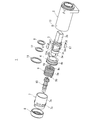
- FIG. 3 is an exploded perspective view of the damper device according to the first embodiment.
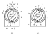
- 3 is a sectional view taken along line III-III of FIG. 1 (FIG. 3A shows a case where the shaft rotates in the closing direction, and FIG. 3B shows a case where the shaft rotates in the opening direction).
- FIG. 6 is a cross section taken along line VI-VI of FIG. 3 (FIG. 6A shows a case where the shaft rotates in the closing direction, and FIG. 6B shows a case where the shaft rotates in the opening direction).
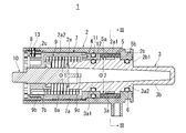
- FIG. 1 shows a sectional view along the axis of a damper device 1 according to a first embodiment of the present invention
- FIG. 2 shows an exploded perspective view of the damper device 1 according to the present embodiment
- the damper device 1 of this embodiment is provided between the toilet bowl and the toilet lid or the seat in order to rotate the toilet lid or the toilet seat at a low speed.
- the damper device 1 includes a case 2 and a shaft 3 rotatable with respect to the case 2.
- One of the case 2 and the shaft 3 is attached to the toilet bowl, and the other is attached to the toilet lid or the toilet seat.
- the toilet lid or toilet seat
- the damper device 1 of the present invention can be used for applications other than the toilet lid or the toilet seat.
- the case 2 has a substantially cylindrical shape and has a fitting hole 2a penetrating the central portion thereof.
- the case 2 has a damper housing portion 2a1 and a coil spring housing portion 2a2 in its axial direction.
- a step is formed between the damper housing portion 2a1 and the coil spring housing portion 2a2.
- An end wall 2b is provided at one end of the case 2 in the axial direction.
- the end wall 2b is formed with a support hole 2b1 for rotatably supporting the shaft 3 penetrating therethrough.
- a screw 2c is formed on the inner surface of the other end of the case 2 in the axial direction.
- the shaft 3 includes a shaft portion 3a that is inserted into the fitting hole 2a of the case 2 and a connecting portion 3b that projects from the end wall 2b of the case 2.
- the shaft portion 3a is rotatably supported by the case 2 by rotatably fitting the journal portions 3a1 and 3a2 formed at both ends thereof to the end wall 2b and the bearing member 4.
- a seal member 6 such as an O-ring for preventing the fluid filled in the damper chamber 5 from leaking is arranged between the journal portion 3a2 and the end wall 2b.
- a groove 3d (see FIG. 2) into which the seal member 6 is fitted is formed on the outer surface of the journal portion 3a2.
- the connecting portion 3b of the shaft 3 has a pair of parallel flat surfaces, and is connected to either the toilet lid (or the toilet seat) or the toilet bowl.
- the shaft 3 is inserted into the fitting hole 2a of the case 2 in one direction (rightward in FIG. 1).
- the step formed on the shaft 3a hits the end wall 2b to prevent the end wall 2b from coming off in one direction (rightward in FIG. 1).
- the bearing member 4 and the spring holding member 7 are inserted into the case 2, and the lid member 8 is screwed into the case 2, so that the shaft 3 is moved in the other direction (left in FIG. 1). (Direction) is prevented from coming off.
- An annular damper chamber 5 is formed between the case 2 and the shaft 3.
- the damper chamber 5 is filled with a viscous fluid or the like.
- the bearing member 4 is annular and is separate from the shaft 3.
- the bearing member 4 is inserted between the case 2 and the shaft 3 in one direction (rightward in FIG. 1) after the damper chamber 5 is filled with the fluid.
- the bearing member 4 forms a partition wall 5a that closes one end of the damper chamber 5 in the axial direction.
- a partition wall 5b that closes the other axial end of the damper chamber 5 is formed on the end wall 2b of the case 2.
- the partition wall 5b that closes the other end of the damper chamber 5 may be formed on the shaft 3 or on a bearing member that is separate from the shaft 3.
- the bearing member 4 is not rotatable with respect to the case 2 and is movable in the axial direction so that the damper force can be adjusted.
- a plurality of protrusions 4 a are formed on the outer surface of the bearing member 4 in the circumferential direction.
- a groove that fits into the protrusion 4a is formed on the inner surface of the fitting hole 2a of the case 2.
- An annular fixed seal member 11 is arranged between the case 2 and the bearing member 4 to prevent the fluid filled in the damper chamber 5 from leaking.
- a groove 4b (see FIG. 2) into which the fixed seal member 11 is fitted is formed on the outer surface of the bearing member 4.
- the shaft 3 is rotatable with respect to the bearing member 4.
- a sliding seal member 12 such as an O-ring, is arranged between the bearing member 4 and the shaft 3 to prevent fluid from leaking.
- a groove 3c (see FIG. 2) into which the sliding seal member 12 is fitted is formed on the outer surface of the shaft 3.
- the sliding seal member 12 is arranged on the outer surface of the shaft 3, the bearing member 4 is arranged on the outer side of the sliding seal member 12, and the fixed seal member 11 is arranged on the outer surface of the bearing member 4, when the shaft 3 rotates.
- the sliding resistance can be suppressed, and stable damper performance can be maintained.
- a coil spring 9 is arranged between the bearing member 4 and the spring holding member 7.
- the coil spring 9 is inserted into the case 2 in one direction (rightward in FIG. 1).
- the coil spring 9 includes a winding portion 9a, one end 9b, and the other end 9c (see FIG. 2).
- One end 9b of the coil spring 9 is connected to the case 2 side.
- one end 9b of the coil spring 9 is connected to the spring holding member 7.
- the spring holding member 7 cannot rotate with respect to the case 2.
- the spring holding member 7 is formed with a hole into which the one end 9b of the coil spring 9 is fitted.
- the one end 9b of the coil spring 9 may be connected to the case 2.
- the other end 9c of the coil spring 9 is connected to the shaft 3.
- the shaft 3 is formed with a notch 3e (see FIG. 2) into which the other end 9c of the coil spring 9 is fitted.
- the coil spring 9 has one end 9b connected to the case 2 side and the other end 9c connected to the shaft 3 side.
- the coil spring 9 exerts a torque on the shaft 3 with respect to the case 2 and urges the toilet lid (or the toilet seat) in the opening direction (arrow Y direction in FIG. 3B). Therefore, the toilet lid (or toilet seat) can be lifted up lightly.
- the bearing member 4 is arranged between the winding portion 9 a of the coil spring 9 and the damper chamber 5.
- the winding portion 9a of the coil spring 9 and the damper chamber 5 are separated from each other in the axial direction. It suffices that at least the winding portion 9a of the coil spring 9 is axially separated from the damper chamber 5, and the other end 9c of the coil spring 9 may be arranged inside the damper chamber 5.
- the outer diameter ⁇ 1 of the winding portion 9a of the coil spring 9 is larger than the inner diameter ⁇ 2 of the damper chamber 5 (the outer diameter ⁇ 2 of the step portion of the shaft 3 (see FIG. 1)).
- the winding portion 9 a of the coil spring 9 is arranged outside the shaft 3.
- the outer diameter ⁇ 1 of the winding portion 9a of the coil spring 9 can be increased without increasing the outer diameter of the case 2. Can be large. Therefore, the wire diameter of the coil spring 9 can be increased, and the torque of the coil spring 9 can be increased. Further, since the bearing member 4 that closes one end of the damper chamber 5 is arranged between the winding portion 9a of the coil spring 9 and the damper chamber 5, the fluid filled in the damper chamber 5 leaks to the coil spring 9 side. Can be prevented.
- the spring holding member 7 has a substantially bottomed cylindrical shape.
- the spring holding member 7 has a tubular portion 7a surrounding the coil spring 9 and a bottom portion 7b to which one end 9b of the coil spring 9 is connected.
- the spring holding member 7 is inserted into the case 2 in one direction (rightward in FIG. 1).
- the spring holding member 7 is not rotatable with respect to the case 2 and is movable in the axial direction so that the damper force can be adjusted.
- a plurality of protrusions 7c are formed on the outer surface of the spring holding member 7 in the circumferential direction. The protrusion 7c fits into a groove formed on the inner surface of the fitting hole 2a of the case 2.
- Numeral 10 is an opening/closing detection axis.
- the open/close detection shaft 10 is inserted into the shaft 3 and is non-rotatably connected to the shaft 3.
- the open/close detection shaft 10 penetrates through the spring holding member 7 and is rotatably supported by the spring holding member 7.
- a magnet (not shown) is attached to the tip of the opening/closing detection shaft 10 exposed from the case 2. Opening and closing of the toilet lid (or toilet seat) can be detected by detecting the magnetic flux of the magnet.
- the open/close detection shaft 10 may be omitted.
- the lid member 8 has a screw on its outer surface that is screwed into the screw 2c on the inner surface of the case 2. After inserting the shaft 3, the bearing member 4, the coil spring 9, the opening/closing detection shaft 10, and the spring holding member 7 into the fitting hole 2 a of the case 2 in the same direction, the lid member 8 is screwed into the case 2 to It is possible to prevent the above-mentioned parts from coming out of the case 2.
- these parts since these parts are inserted into the case 2 in the same direction, only one lid member 8 is required, and the damper device 1 can be easily assembled.
- the spring holding member 7 is sandwiched between the lid member 8 and the bearing member 4.
- the lid member 8 pushes the bearing member 4 via the spring holding member 7, so that the partition wall 5a of the bearing member 4 and the blade portion 15 and the valve body 17 (see FIG. 3).
- the damper force can be adjusted by adjusting the gap.
- the damper force can be easily adjusted on the side of the shaft 3 opposite to the connecting portion 3b.
- the lid member 8 and the spring holding member 7 are fixed to the case 2 by the pin 13.
- the lid member 8 may be fixed to the case 2 by welding or the like without using the pin 13.
- a blade portion 15 is formed on the outer surface of the shaft portion 3 a facing the damper chamber 5, and a partition wall portion 16 is formed on the inner surface of the case 2 facing the damper chamber 5.
- the blade portion 15 and the partition wall portion 16 divide the interior of the damper chamber 5 into four in the circumferential direction to form two first chambers S1 and two second chambers S2. It should be noted that the blade portion 15 and the partition wall portion 16 may be formed one by one to form one first chamber S1 and one second chamber S2.
- the blade portion 15 has a pair of protrusions 15a and 15b having a V-shaped cross section.
- a cutout 15b1 (see FIG. 2) through which fluid can pass without resistance is formed in one of the protrusions 15b.
- a valve body 17 as a flow rate control unit is housed in the valve chamber between the protrusions 15a and 15b. As shown in FIG. 3A, when the shaft 3 rotates in the closing direction (X direction in the drawing), the valve body 17 closes the flow path between the protrusion 15a and the case 2, and the second chamber S2 of the second chamber S2 is closed. The fluid is prevented from flowing to the first chamber S1 on the left side.
- the fluid in the second chamber S2 flows into the first chamber S1 adjacent to the right through the minute gap between the partition wall portion 16 and the shaft portion 3a. Therefore, when the shaft 3 rotates in the closing direction, a damper force acts on the shaft 3 and the rotational speed of the shaft 3 in the closing direction is suppressed. Further, since the shaft 3 is biased in the opening direction by the coil spring 9, the rotational speed of the shaft 3 in the closing direction is also suppressed by the coil spring 9.
- the valve body 17 opens the flow path between the projection 15a and the case 2 to open the first chamber.
- the fluid of S1 is allowed to flow to the second chamber S2 on the left side. Since the fluid in the first chamber S1 can flow into the second chamber S2 through the notch 15b1 without resistance, the shaft 3 rotates in the opening direction without resistance.
- the damper force generated when the shaft 3 rotates in the opening direction is smaller than the damper force generated when the shaft 3 rotates in the closing direction. Since the shaft 3 is biased in the opening direction by the coil spring 9, the toilet lid (or toilet seat) can be lifted with a light force.
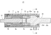
- FIG. 4 shows a sectional view of the damper device 21 according to the second embodiment of the present invention
- FIG. 5 shows an exploded perspective view of the damper device 21.
- the damper device 21 of the second embodiment also includes the case 2, the shaft 22, the bearing member 23, the coil spring 9, the spring holding member 7, the open/close detection shaft 10, and the lid member 8.
- the configurations of the case 2, the coil spring 9, the spring holding member 7, the opening/closing detection shaft 10, and the lid member 8 are substantially the same as those in the first embodiment, and therefore, the same reference numerals are given and the description thereof will be omitted.
- the shaft 22 includes a shaft portion 22a that is inserted into the fitting hole 2a of the case 2 and a connecting portion 22b that projects from the end wall 2b of the case 2.
- One end of the shaft portion 22a is non-rotatably fitted to the bearing member 23.
- a pair of parallel flat surfaces 22c (see FIG. 5) is formed at one end of the shaft portion 22a.
- the shaft portion 22 a is rotatably supported by the case 2 via a bearing member 23.
- the journal portion 22d at the other end of the shaft portion 22a is rotatably supported by the end wall 2b of the case 2.
- the seal member 6 that prevents the fluid filled in the damper chamber 25 from leaking is disposed between the journal portion 22d and the end wall 2b.
- the bearing member 23 forms a partition wall 25a that closes one end of the damper chamber 25 in the axial direction.
- the bearing member 23 is rotatable with respect to the case 2.
- a sliding seal member 27 such as an O-ring that prevents the fluid filled in the damper chamber 25 from leaking is disposed between the case 2 and the bearing member 23.
- a groove 23 a (see FIG. 5) into which the sliding seal member 27 is fitted is formed on the outer surface of the bearing member 23.
- the coil spring 9 has one end 9b connected to the case 2 side and the other end 9c connected to the shaft 22 side. One end 9b of the coil spring 9 is connected to the spring holding member 7. The other end 9c of the coil spring 9 is connected to the bearing member 23.
- the coil spring 9 exerts a torque on the shaft 22 with respect to the case 2 and urges the toilet lid (or toilet seat) in the opening direction (arrow Y direction in FIG. 6B).
- a bearing member 23 is arranged between the winding portion 9 a of the coil spring 9 and the damper chamber 25.
- the winding portion 9a of the coil spring 9 and the damper chamber 25 are separated from each other in the axial direction. Therefore, the outer diameter of the winding portion 9a of the coil spring 9 can be increased without increasing the outer diameter of the case 2. Further, since the bearing member 23 that closes one end of the damper chamber 25 is arranged between the winding portion 9a of the coil spring 9 and the damper chamber 25, the fluid filled in the damper chamber 25 leaks to the coil spring 9 side. Can be prevented.
- a blade portion 29 is formed on the outer surface of the shaft portion 22 a facing the damper chamber 25, and a partition wall portion 16 is formed on the inner surface of the case 2 facing the damper chamber 25. To be done.
- the blade portion 29 and the partition wall portion 16 divide the interior of the damper chamber 25 into four in the circumferential direction to form two first chambers S1 and two second chambers S2.
- a valve body 31 having a U-shaped cross section is mounted on the partition wall portion 16 of the damper chamber 25 as a flow rate control unit.
- the valve body 31 includes a pair of facing walls 31a and 31b and a connecting wall 31c that connects the pair of facing walls 31a and 31b (see FIG. 5).
- a shallow notch 31a1 is formed in one opposing wall 31a, and a deep notch 31b1 is formed in the other opposing wall 31b.
- the facing wall 31a of the valve body 31 abuts on the partition wall portion 16, and the facing wall 31b of the valve body 31 moves. It is separated from the partition wall portion 16.
- the facing wall 31a of the valve body 31 is separated from the partition wall portion 16, and the facing wall 31b is a partition wall. Abut on the portion 16. Therefore, the valve body 31 allows the fluid in the first chamber S1 to flow to the second chamber S2 adjacent to the left through the notch 31b1 in the facing wall 31b and the notch 31a1 in the facing wall 31a. Since the fluid in the first chamber S1 can flow into the second chamber S2 without resistance through the notches 31b1 and 31a1, the shaft 22 rotates in the opening direction without resistance.
- the damper force is generated only when the shaft rotates in the X direction, but the damper force may be generated when the shaft rotates in either the X direction or the Y direction. ..
Landscapes
- Engineering & Computer Science (AREA)
- General Engineering & Computer Science (AREA)
- Mechanical Engineering (AREA)
- Health & Medical Sciences (AREA)
- Public Health (AREA)
- Fluid-Damping Devices (AREA)
- Toilet Supplies (AREA)
Abstract
L'invention concerne un dispositif amortisseur dans lequel le couple d'un ressort hélicoïdal peut être augmenté sans augmenter le diamètre externe d'un boîtier. Ce dispositif amortisseur (1) est pourvu : d'un boîtier (2); d'un arbre (3) qui peut tourner par rapport au boîtier (2); d'un fluide qui remplit une chambre d'amortisseur (5) formé entre le boîtier (2) et l'arbre (3); un élément de palier (4) qui forme une paroi de séparation (5a) qui ferme une extrémité axiale de la chambre d'amortisseur (5) et est un corps séparé de l'arbre (3); et un ressort hélicoïdal (9) qui a une extrémité reliée au boîtier (2) et l'autre extrémité reliée à l'arbre (3) ou à l'élément de support (4) et qui applique un couple à l'arbre (3) par rapport au boîtier (2). L'élément de palier (4) est disposé entre une partie d'enroulement (9a) du ressort hélicoïdal (9) et la chambre d'amortisseur (5), et la partie d'enroulement (9a) du ressort hélicoïdal (9) et la chambre d'amortisseur (5) sont espacées axialement l'une de l'autre.
Priority Applications (4)
| Application Number | Priority Date | Filing Date | Title |
|---|---|---|---|
| US17/309,866 US11732517B2 (en) | 2018-12-27 | 2019-12-12 | Damper device |
| CN201980080874.3A CN113163995B (zh) | 2018-12-27 | 2019-12-12 | 缓冲装置 |
| EP19906086.4A EP3903655A4 (fr) | 2018-12-27 | 2019-12-12 | Dispositif amortisseur |
| JP2020530710A JP6959451B2 (ja) | 2018-12-27 | 2019-12-12 | ダンパ装置 |
Applications Claiming Priority (2)
| Application Number | Priority Date | Filing Date | Title |
|---|---|---|---|
| JP2018-244675 | 2018-12-27 | ||
| JP2018244675 | 2018-12-27 |
Publications (1)
| Publication Number | Publication Date |
|---|---|
| WO2020137570A1 true WO2020137570A1 (fr) | 2020-07-02 |
Family
ID=71127155
Family Applications (1)
| Application Number | Title | Priority Date | Filing Date |
|---|---|---|---|
| PCT/JP2019/048623 Ceased WO2020137570A1 (fr) | 2018-12-27 | 2019-12-12 | Dispositif amortisseur |
Country Status (5)
| Country | Link |
|---|---|
| US (1) | US11732517B2 (fr) |
| EP (1) | EP3903655A4 (fr) |
| JP (1) | JP6959451B2 (fr) |
| CN (1) | CN113163995B (fr) |
| WO (1) | WO2020137570A1 (fr) |
Cited By (1)
| Publication number | Priority date | Publication date | Assignee | Title |
|---|---|---|---|---|
| WO2025033175A1 (fr) * | 2023-08-04 | 2025-02-13 | スガツネ工業株式会社 | Dispositif amortisseur à retard |
Families Citing this family (3)
| Publication number | Priority date | Publication date | Assignee | Title |
|---|---|---|---|---|
| IT201900004791A1 (it) * | 2019-03-29 | 2020-09-29 | Colcom Group S P A | Dispositivo a cerniera per ante in vetro o similari |
| DE102020201318A1 (de) * | 2020-02-04 | 2021-08-05 | Sacs Aerospace Gmbh | Scharnieranordnung |
| JP7391823B2 (ja) * | 2020-11-19 | 2023-12-05 | オイレス工業株式会社 | ロータリダンパ |
Citations (5)
| Publication number | Priority date | Publication date | Assignee | Title |
|---|---|---|---|---|
| JPS51122927A (en) * | 1975-04-19 | 1976-10-27 | Tokico Ltd | Door closer |
| JP3280941B2 (ja) | 1999-09-30 | 2002-05-13 | 東陶機器株式会社 | 回転ダンパ |
| JP2002371741A (ja) * | 2001-06-19 | 2002-12-26 | Nifco Inc | 回動装置 |
| JP2010019300A (ja) * | 2008-07-09 | 2010-01-28 | Panasonic Corp | ダンパー装置 |
| JP2018204618A (ja) * | 2017-05-30 | 2018-12-27 | アイシン精機株式会社 | 回転ダンパおよび便座装置 |
Family Cites Families (13)
| Publication number | Priority date | Publication date | Assignee | Title |
|---|---|---|---|---|
| JPH0678703B2 (ja) * | 1989-05-02 | 1994-10-05 | スガツネ工業株式会社 | 粘性流体を用いたフラップ扉用ダンパー |
| US5388281A (en) * | 1993-09-27 | 1995-02-14 | Wiklund; Ken | Automatic closure mechanism for a toilet seat |
| RU2253060C2 (ru) * | 2000-10-30 | 2005-05-27 | Сугацуне Когио Ко., Лтд | Поворотный амортизатор |
| US20090025181A1 (en) * | 2007-07-26 | 2009-01-29 | George Burger | Slow Closing Hinge Apparatus |
| JP5179506B2 (ja) * | 2007-10-05 | 2013-04-10 | スガツネ工業株式会社 | ヒンジ装置 |
| RU2440522C1 (ru) * | 2007-12-26 | 2012-01-20 | Сугацуне Когио Ко., Лтд. | Поворотный демпфер |
| KR100937780B1 (ko) * | 2009-06-08 | 2010-01-20 | 주식회사 삼홍테크 | 캠을 이용한 오일 댐퍼 |
| KR101544303B1 (ko) * | 2011-08-31 | 2015-08-12 | 스가쓰네 고우교 가부시키가이샤 | 회전 댐퍼 및 댐퍼가 형성된 힌지 장치 |
| US9492041B1 (en) * | 2015-08-04 | 2016-11-15 | Regent (Hong-Kong) Limited Speedy | Adjustable rotary damper for toilet seats |
| JP2017106490A (ja) * | 2015-12-07 | 2017-06-15 | 大豊工業株式会社 | 内燃機関の軸受構造 |
| JP6571551B2 (ja) * | 2016-01-29 | 2019-09-04 | 日本電産サンキョー株式会社 | 流体ダンパ装置およびダンパ付き機器 |
| JP2017133668A (ja) * | 2016-01-29 | 2017-08-03 | 日本電産サンキョー株式会社 | 流体ダンパ装置およびダンパ付き機器 |
| US11072958B2 (en) * | 2018-08-07 | 2021-07-27 | Kem Hongkong Limited | Damper hinge and western-style toilet using the same |
-
2019
- 2019-12-12 EP EP19906086.4A patent/EP3903655A4/fr not_active Withdrawn
- 2019-12-12 WO PCT/JP2019/048623 patent/WO2020137570A1/fr not_active Ceased
- 2019-12-12 US US17/309,866 patent/US11732517B2/en active Active
- 2019-12-12 CN CN201980080874.3A patent/CN113163995B/zh active Active
- 2019-12-12 JP JP2020530710A patent/JP6959451B2/ja active Active
Patent Citations (5)
| Publication number | Priority date | Publication date | Assignee | Title |
|---|---|---|---|---|
| JPS51122927A (en) * | 1975-04-19 | 1976-10-27 | Tokico Ltd | Door closer |
| JP3280941B2 (ja) | 1999-09-30 | 2002-05-13 | 東陶機器株式会社 | 回転ダンパ |
| JP2002371741A (ja) * | 2001-06-19 | 2002-12-26 | Nifco Inc | 回動装置 |
| JP2010019300A (ja) * | 2008-07-09 | 2010-01-28 | Panasonic Corp | ダンパー装置 |
| JP2018204618A (ja) * | 2017-05-30 | 2018-12-27 | アイシン精機株式会社 | 回転ダンパおよび便座装置 |
Cited By (1)
| Publication number | Priority date | Publication date | Assignee | Title |
|---|---|---|---|---|
| WO2025033175A1 (fr) * | 2023-08-04 | 2025-02-13 | スガツネ工業株式会社 | Dispositif amortisseur à retard |
Also Published As
| Publication number | Publication date |
|---|---|
| EP3903655A4 (fr) | 2022-09-28 |
| US20220049535A1 (en) | 2022-02-17 |
| CN113163995A (zh) | 2021-07-23 |
| EP3903655A1 (fr) | 2021-11-03 |
| CN113163995B (zh) | 2023-02-17 |
| US11732517B2 (en) | 2023-08-22 |
| JPWO2020137570A1 (ja) | 2021-02-18 |
| JP6959451B2 (ja) | 2021-11-02 |
Similar Documents
| Publication | Publication Date | Title |
|---|---|---|
| WO2020137570A1 (fr) | Dispositif amortisseur | |
| JP4370590B2 (ja) | 回転ダンパ | |
| WO2002036984A1 (fr) | Amortisseur rotatif | |
| US5664286A (en) | Hinge mechanism for supporting the seat or the seat lid of a toilet bowl | |
| US8220603B2 (en) | Rotary damper with one-way clutch | |
| US9371675B2 (en) | Rotary damper and hinge device with damper | |
| US8935829B2 (en) | Hinge device with damper | |
| US11072958B2 (en) | Damper hinge and western-style toilet using the same | |
| JP2955813B2 (ja) | オイルダンパを用いた鍵盤蓋開閉装置 | |
| JP5681047B2 (ja) | 回転ダンパ | |
| CN110621903B (zh) | 具备简易自立机构的旋转阻尼器 | |
| JP5762170B2 (ja) | 回転ダンパ | |
| JP2007270955A (ja) | ロータリーダンパーの破壊防止機構 | |
| JP4965474B2 (ja) | ダンパー装置 | |
| JP3427284B2 (ja) | 回転ダンパ及び同ダンパを用いた蓋の開閉装置 | |
| JP2005249003A (ja) | 回転伝達装置 | |
| JPH08270703A (ja) | 回転ダンパー | |
| JP5200431B2 (ja) | 便座の自立保持機構 | |
| KR100418055B1 (ko) | 덮개의 제동구조 | |
| JP2009185522A (ja) | ヒンジ装置 | |
| JP3486318B2 (ja) | ソフト閉止ダンパー機構 | |
| JP2020023996A (ja) | ダンパーヒンジ | |
| WO2026009155A1 (fr) | Amortisseur rotatif à stabilisation de couple | |
| JPH07293624A (ja) | リフト閉止ユニットの開閉弁装置 |
Legal Events
| Date | Code | Title | Description |
|---|---|---|---|
| ENP | Entry into the national phase |
Ref document number: 2020530710 Country of ref document: JP Kind code of ref document: A |
|
| 121 | Ep: the epo has been informed by wipo that ep was designated in this application |
Ref document number: 19906086 Country of ref document: EP Kind code of ref document: A1 |
|
| NENP | Non-entry into the national phase |
Ref country code: DE |
|
| ENP | Entry into the national phase |
Ref document number: 2019906086 Country of ref document: EP Effective date: 20210727 |