WO2020138082A1 - Évaporateur et caloduc de type boucle - Google Patents
Évaporateur et caloduc de type boucle Download PDFInfo
- Publication number
- WO2020138082A1 WO2020138082A1 PCT/JP2019/050600 JP2019050600W WO2020138082A1 WO 2020138082 A1 WO2020138082 A1 WO 2020138082A1 JP 2019050600 W JP2019050600 W JP 2019050600W WO 2020138082 A1 WO2020138082 A1 WO 2020138082A1
- Authority
- WO
- WIPO (PCT)
- Prior art keywords
- heat exchange
- evaporator
- working fluid
- heat
- inclination
- Prior art date
- Legal status (The legal status is an assumption and is not a legal conclusion. Google has not performed a legal analysis and makes no representation as to the accuracy of the status listed.)
- Ceased
Links
Images

Classifications
-
- F—MECHANICAL ENGINEERING; LIGHTING; HEATING; WEAPONS; BLASTING
- F28—HEAT EXCHANGE IN GENERAL
- F28D—HEAT-EXCHANGE APPARATUS, NOT PROVIDED FOR IN ANOTHER SUBCLASS, IN WHICH THE HEAT-EXCHANGE MEDIA DO NOT COME INTO DIRECT CONTACT
- F28D15/00—Heat-exchange apparatus with the intermediate heat-transfer medium in closed tubes passing into or through the conduit walls ; Heat-exchange apparatus employing intermediate heat-transfer medium or bodies
- F28D15/02—Heat-exchange apparatus with the intermediate heat-transfer medium in closed tubes passing into or through the conduit walls ; Heat-exchange apparatus employing intermediate heat-transfer medium or bodies in which the medium condenses and evaporates, e.g. heat pipes
- F28D15/0266—Heat-exchange apparatus with the intermediate heat-transfer medium in closed tubes passing into or through the conduit walls ; Heat-exchange apparatus employing intermediate heat-transfer medium or bodies in which the medium condenses and evaporates, e.g. heat pipes with separate evaporating and condensing chambers connected by at least one conduit; Loop-type heat pipes; with multiple or common evaporating or condensing chambers
-
- F—MECHANICAL ENGINEERING; LIGHTING; HEATING; WEAPONS; BLASTING
- F16—ENGINEERING ELEMENTS AND UNITS; GENERAL MEASURES FOR PRODUCING AND MAINTAINING EFFECTIVE FUNCTIONING OF MACHINES OR INSTALLATIONS; THERMAL INSULATION IN GENERAL
- F16K—VALVES; TAPS; COCKS; ACTUATING-FLOATS; DEVICES FOR VENTING OR AERATING
- F16K15/00—Check valves
- F16K15/18—Check valves with actuating mechanism; Combined check valves and actuated valves
- F16K15/184—Combined check valves and actuated valves
-
- F—MECHANICAL ENGINEERING; LIGHTING; HEATING; WEAPONS; BLASTING
- F28—HEAT EXCHANGE IN GENERAL
- F28D—HEAT-EXCHANGE APPARATUS, NOT PROVIDED FOR IN ANOTHER SUBCLASS, IN WHICH THE HEAT-EXCHANGE MEDIA DO NOT COME INTO DIRECT CONTACT
- F28D15/00—Heat-exchange apparatus with the intermediate heat-transfer medium in closed tubes passing into or through the conduit walls ; Heat-exchange apparatus employing intermediate heat-transfer medium or bodies
- F28D15/02—Heat-exchange apparatus with the intermediate heat-transfer medium in closed tubes passing into or through the conduit walls ; Heat-exchange apparatus employing intermediate heat-transfer medium or bodies in which the medium condenses and evaporates, e.g. heat pipes
- F28D15/04—Heat-exchange apparatus with the intermediate heat-transfer medium in closed tubes passing into or through the conduit walls ; Heat-exchange apparatus employing intermediate heat-transfer medium or bodies in which the medium condenses and evaporates, e.g. heat pipes with tubes having a capillary structure
- F28D15/043—Heat-exchange apparatus with the intermediate heat-transfer medium in closed tubes passing into or through the conduit walls ; Heat-exchange apparatus employing intermediate heat-transfer medium or bodies in which the medium condenses and evaporates, e.g. heat pipes with tubes having a capillary structure forming loops, e.g. capillary pumped loops
-
- F—MECHANICAL ENGINEERING; LIGHTING; HEATING; WEAPONS; BLASTING
- F28—HEAT EXCHANGE IN GENERAL
- F28D—HEAT-EXCHANGE APPARATUS, NOT PROVIDED FOR IN ANOTHER SUBCLASS, IN WHICH THE HEAT-EXCHANGE MEDIA DO NOT COME INTO DIRECT CONTACT
- F28D15/00—Heat-exchange apparatus with the intermediate heat-transfer medium in closed tubes passing into or through the conduit walls ; Heat-exchange apparatus employing intermediate heat-transfer medium or bodies
- F28D15/02—Heat-exchange apparatus with the intermediate heat-transfer medium in closed tubes passing into or through the conduit walls ; Heat-exchange apparatus employing intermediate heat-transfer medium or bodies in which the medium condenses and evaporates, e.g. heat pipes
- F28D15/06—Control arrangements therefor
-
- F—MECHANICAL ENGINEERING; LIGHTING; HEATING; WEAPONS; BLASTING
- F28—HEAT EXCHANGE IN GENERAL
- F28F—DETAILS OF HEAT-EXCHANGE AND HEAT-TRANSFER APPARATUS, OF GENERAL APPLICATION
- F28F27/00—Control arrangements or safety devices specially adapted for heat-exchange or heat-transfer apparatus
- F28F27/02—Control arrangements or safety devices specially adapted for heat-exchange or heat-transfer apparatus for controlling the distribution of heat-exchange media between different channels
-
- H—ELECTRICITY
- H05—ELECTRIC TECHNIQUES NOT OTHERWISE PROVIDED FOR
- H05K—PRINTED CIRCUITS; CASINGS OR CONSTRUCTIONAL DETAILS OF ELECTRIC APPARATUS; MANUFACTURE OF ASSEMBLAGES OF ELECTRICAL COMPONENTS
- H05K7/00—Constructional details common to different types of electric apparatus
- H05K7/20—Modifications to facilitate cooling, ventilating, or heating
- H05K7/20536—Modifications to facilitate cooling, ventilating, or heating for racks or cabinets of standardised dimensions, e.g. electronic racks for aircraft or telecommunication equipment
- H05K7/20663—Liquid coolant with phase change, e.g. heat pipes
- H05K7/20672—Liquid coolant with phase change, e.g. heat pipes within sub-racks for removing heat from electronic boards
-
- H—ELECTRICITY
- H05—ELECTRIC TECHNIQUES NOT OTHERWISE PROVIDED FOR
- H05K—PRINTED CIRCUITS; CASINGS OR CONSTRUCTIONAL DETAILS OF ELECTRIC APPARATUS; MANUFACTURE OF ASSEMBLAGES OF ELECTRICAL COMPONENTS
- H05K7/00—Constructional details common to different types of electric apparatus
- H05K7/20—Modifications to facilitate cooling, ventilating, or heating
- H05K7/20536—Modifications to facilitate cooling, ventilating, or heating for racks or cabinets of standardised dimensions, e.g. electronic racks for aircraft or telecommunication equipment
- H05K7/20663—Liquid coolant with phase change, e.g. heat pipes
- H05K7/2069—Liquid coolant with phase change, e.g. heat pipes within rooms for removing heat from cabinets
-
- F—MECHANICAL ENGINEERING; LIGHTING; HEATING; WEAPONS; BLASTING
- F28—HEAT EXCHANGE IN GENERAL
- F28D—HEAT-EXCHANGE APPARATUS, NOT PROVIDED FOR IN ANOTHER SUBCLASS, IN WHICH THE HEAT-EXCHANGE MEDIA DO NOT COME INTO DIRECT CONTACT
- F28D15/00—Heat-exchange apparatus with the intermediate heat-transfer medium in closed tubes passing into or through the conduit walls ; Heat-exchange apparatus employing intermediate heat-transfer medium or bodies
- F28D15/02—Heat-exchange apparatus with the intermediate heat-transfer medium in closed tubes passing into or through the conduit walls ; Heat-exchange apparatus employing intermediate heat-transfer medium or bodies in which the medium condenses and evaporates, e.g. heat pipes
- F28D2015/0216—Heat-exchange apparatus with the intermediate heat-transfer medium in closed tubes passing into or through the conduit walls ; Heat-exchange apparatus employing intermediate heat-transfer medium or bodies in which the medium condenses and evaporates, e.g. heat pipes having particular orientation, e.g. slanted, or being orientation-independent
-
- F—MECHANICAL ENGINEERING; LIGHTING; HEATING; WEAPONS; BLASTING
- F28—HEAT EXCHANGE IN GENERAL
- F28D—HEAT-EXCHANGE APPARATUS, NOT PROVIDED FOR IN ANOTHER SUBCLASS, IN WHICH THE HEAT-EXCHANGE MEDIA DO NOT COME INTO DIRECT CONTACT
- F28D21/00—Heat-exchange apparatus not covered by any of the groups F28D1/00 - F28D20/00
- F28D2021/0019—Other heat exchangers for particular applications; Heat exchange systems not otherwise provided for
- F28D2021/0021—Other heat exchangers for particular applications; Heat exchange systems not otherwise provided for for aircrafts or cosmonautics
-
- F—MECHANICAL ENGINEERING; LIGHTING; HEATING; WEAPONS; BLASTING
- F28—HEAT EXCHANGE IN GENERAL
- F28D—HEAT-EXCHANGE APPARATUS, NOT PROVIDED FOR IN ANOTHER SUBCLASS, IN WHICH THE HEAT-EXCHANGE MEDIA DO NOT COME INTO DIRECT CONTACT
- F28D21/00—Heat-exchange apparatus not covered by any of the groups F28D1/00 - F28D20/00
- F28D2021/0019—Other heat exchangers for particular applications; Heat exchange systems not otherwise provided for
- F28D2021/0028—Other heat exchangers for particular applications; Heat exchange systems not otherwise provided for for cooling heat generating elements, e.g. for cooling electronic components or electric devices
-
- F—MECHANICAL ENGINEERING; LIGHTING; HEATING; WEAPONS; BLASTING
- F28—HEAT EXCHANGE IN GENERAL
- F28D—HEAT-EXCHANGE APPARATUS, NOT PROVIDED FOR IN ANOTHER SUBCLASS, IN WHICH THE HEAT-EXCHANGE MEDIA DO NOT COME INTO DIRECT CONTACT
- F28D21/00—Heat-exchange apparatus not covered by any of the groups F28D1/00 - F28D20/00
- F28D2021/0019—Other heat exchangers for particular applications; Heat exchange systems not otherwise provided for
- F28D2021/008—Other heat exchangers for particular applications; Heat exchange systems not otherwise provided for for vehicles
-
- F—MECHANICAL ENGINEERING; LIGHTING; HEATING; WEAPONS; BLASTING
- F28—HEAT EXCHANGE IN GENERAL
- F28F—DETAILS OF HEAT-EXCHANGE AND HEAT-TRANSFER APPARATUS, OF GENERAL APPLICATION
- F28F2250/00—Arrangements for modifying the flow of the heat exchange media, e.g. flow guiding means; Particular flow patterns
-
- H—ELECTRICITY
- H10—SEMICONDUCTOR DEVICES; ELECTRIC SOLID-STATE DEVICES NOT OTHERWISE PROVIDED FOR
- H10W—GENERIC PACKAGES, INTERCONNECTIONS, CONNECTORS OR OTHER CONSTRUCTIONAL DETAILS OF DEVICES COVERED BY CLASS H10
- H10W40/00—Arrangements for thermal protection or thermal control
- H10W40/70—Fillings or auxiliary members in containers or in encapsulations for thermal protection or control
- H10W40/73—Fillings or auxiliary members in containers or in encapsulations for thermal protection or control for cooling by change of state
Definitions
- the present invention relates to an evaporator and a loop heat pipe including the evaporator.
- loop type heat pipe that carries out high density heat transport using the phase change of the working fluid.
- a heat transport system using such a loop heat pipe has been used for cooling electronic devices such as computers and home appliances.
- As a loop heat pipe there is one that circulates a working fluid by utilizing capillary force and/or gravity.
- the loop-type heat pipe has a closed loop formed by an evaporator, a condenser, a vapor pipe connecting the evaporator and the condenser, and a liquid pipe connecting the condenser and the evaporator.
- the working fluid is enclosed in the closed loop.
- the liquid-phase working fluid is heated by the heat transmitted from the heating element, and a part of the working fluid is changed to gas.
- the gas-liquid two-phase working fluid moves in the steam pipe due to the pressure difference and buoyancy, and reaches the condenser.
- the condenser the working fluid is cooled and converted into a liquid.
- the liquid-phase working fluid is returned to the evaporator by capillary force and/or gravity. In this way, in the loop heat pipe, the working fluid circulates in the two-phase closed loop, whereby the heat is transported from the evaporator to the condenser, and the heating element thermally connected to the evaporator is cooled.
- Patent Document 1 discloses a loop heat pipe configured as an exhaust heat recovery device for recovering exhaust heat from a water-cooled engine mounted on a vehicle.
- This loop-type heat pipe includes an evaporator that exchanges heat between exhaust gas from a water-cooled engine and working fluid (water) inside.
- This evaporator is connected to a heat exchange part formed by stacking heat transfer tubes and fins that extend linearly in the vertical direction, a lower pipe connected to the lower ends of a plurality of tubes, and an upper end of the plurality of tubes. It is equipped with a pipe.
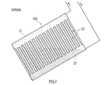
- FIG. 7 is a diagram showing a configuration of a conventional evaporator 200.
- a conventional evaporator 200 shown in FIG. 7 includes a plurality of vertically extending inlet portions 22, an outlet portion 21 disposed above the inlet portion 22, a space between the inlet portion 22 and the outlet portion 21, and a vertically extending portion. And a heat exchange flow path 23.
- the liquid-phase working fluid flows in the direction in which the potential energy is small, so that the amount of the liquid-phase working fluid in the heat exchange passage 23 is uneven.
- the heat exchange flow path 23 is not effectively used due to the small amount of the working fluid in the liquid phase, and there is a possibility that sufficient heat exchange between the working fluid and the heat source fluid is not performed.
- the present invention has been made in view of the above circumstances, and in an evaporator provided with a plurality of heat exchange passages extending in the vertical direction, and in a loop heat pipe provided with the same, when the posture of the evaporator is inclined. It is an object of the present invention to reduce the deviation in the amount of working fluid in the liquid phase between the plurality of heat exchange passages.
- An evaporator is an evaporator that is mounted on a transportation machine and that converts at least a part of a working fluid in a liquid phase into a gas by receiving heat from a heat source, A plurality of heat exchange units that are arranged horizontally in a state in which the transport machine is placed on a horizontal plane, and whose postures are integrally changed; A distribution pipe that is connected to each of the heat exchange units and supplies the working fluid in a liquid phase to the heat exchange units, A valve that is provided in each of the distribution pipes and that blocks the passage of the flow of the working fluid from the heat exchange unit toward the distribution pipe by the valve while at least the inclination of the heat exchange unit is equal to or greater than a predetermined threshold value.
- Each of the heat exchange units includes an inlet portion connected to the distribution pipe, and at least one heat exchange passage linearly extending upward from the inlet portion, and the working fluid passing through the heat exchange passage. And a heat exchange section for exchanging heat with the heat source.
- the loop heat pipe connects the evaporator, a condenser that changes the working fluid in a vapor phase into a liquid, an outlet of the evaporator, and an inlet of the condenser.
- a steam pipe and a liquid pipe connecting the outlet of the condenser and the inlet of the evaporator are provided.
- the working fluid in the liquid phase tends to flow in the direction of smaller potential energy.
- the valve blocks the flow of the working fluid from the heat exchange unit to the distribution pipe, the working fluid in the liquid phase in the heat exchange unit flows out to the distribution pipe or to another heat exchange unit through the distribution pipe. It does not leak.
- the deviation of the amount of working fluid in the liquid phase between the heat exchange channels is small. Therefore, when the posture of the evaporator is tilted, it is possible to reduce the number of heat exchange passages in which there is no liquid-phase working fluid (or there is a small amount of liquid-phase working fluid).
- the exchange channel can be effectively used.
- an evaporator including a plurality of heat exchange passages extending in the vertical direction, and a loop heat pipe including the same, between the plurality of heat exchange passages when the posture of the evaporator is inclined. It is possible to provide the one that can reduce the deviation of the amount of the working fluid in the liquid phase.
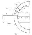
- FIG. 1 is a diagram showing a schematic configuration of an aircraft equipped with a loop heat pipe according to an embodiment of the present invention.
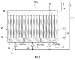
- FIG. 2 is a diagram showing the configuration of the evaporator according to the first embodiment.
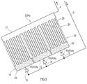
- FIG. 3 is a diagram illustrating a state in which the evaporator shown in FIG. 2 is tilted from the reference posture.
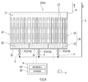
- FIG. 4 is a diagram showing the configuration of the evaporator according to the second embodiment.
- FIG. 5 is a perspective view which shows the structure of the evaporator which concerns on 3rd Embodiment.
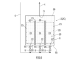
- FIG. 6 is a schematic diagram showing the internal structure of the evaporator shown in FIG.
- FIG. 7 is a figure which shows the structure of the conventional evaporator.
- FIG. 1 is a diagram showing an aircraft 50 as an example of a transportation machine equipped with a loop heat pipe 10 according to an embodiment of the present invention.
- the loop heat pipe 10 shown in FIG. 1 includes an evaporator 2, a steam pipe 4, a condenser 3, and a liquid pipe 5 that form a closed loop.
- a working fluid is enclosed in the closed loop.
- the working fluid naturally circulates in the loop heat pipe 10 by utilizing phase change and gravity.
- the working fluid is not particularly limited, and is a condensable fluid that has been conventionally used as a working fluid for heat pipes (for example, water, alcohol, ammonia, fluorocarbon, hydrofluorocarbon, hydrofluoroether, and a mixed solution thereof). Etc.).
- the liquid-phase working fluid absorbs heat from the heat source fluid, and part of it boils and changes to gas.
- the gas-phase or gas-liquid two-phase working fluid moves in the steam pipe 4 connecting the outlet of the evaporator 2 and the inlet of the condenser 3 due to a pressure difference or buoyancy, and reaches the condenser 3.
- the condenser 3 is installed above the evaporator 2.
- a cooling flow path (not shown) is formed in the condenser 3, and the vapor-phase or two-phase working fluid radiates heat while passing through the cooling flow path and is cooled and changed to a liquid.
- the liquid-phase working fluid descends by gravity in the liquid pipe 5 that connects the outlet of the condenser 3 and the inlet of the evaporator 2, and returns to the evaporator 2.
- the loop type heat pipe 10 described above is suitable for being mounted on a transport aircraft whose posture changes.
- transport aircraft include ships (including submersibles), railway vehicles, automobiles, and aircraft.
- FIG. 1 shows a part of the fuselage 51 and the main wing 53 of the aircraft 50.
- the body 51 has a multi-layer structure including an outer plate 52 and an inner wall 54 provided on the passenger side of the outer plate 52.
- a cooling chamber 55 is formed between the outer plate 52 and the inner wall 54.
- the inside of the cooling chamber 55 has a low temperature due to the cold heat transmitted from the outer plate 52 which is exposed to the outside air having a temperature significantly lower than that of the ground during flight.
- the outer plate 52 may be provided with an air inlet and an air outlet that communicate with the cooling chamber 55, and the outside air may be introduced into the cooling chamber 55 during flight.
- the aircraft 50 is equipped with the heat source 99 and the loop heat pipe 10 that cools the heat source 99.
- the heat source 99 is not particularly limited, but for example, electronic devices including heat generating components such as a control panel, an engine control unit (ECU), and other computers, mechanical components such as bearings that generate frictional heat, and heat generating elements such as batteries and the like. , Cabin air, etc.
- the evaporator 2 is thermally connected to the heat source 99, and the condenser 3 is arranged in the cooling chamber 55. Inside the cooling chamber 55, a fan 56 for forcibly ventilating the condenser 3 is provided. In this condenser 3, the working fluid is condensed by using the cold heat of the outside air.
- FIG. 2 is a diagram showing a configuration of the evaporator 2A according to the first embodiment
- FIG. 3 is a plan view illustrating a state in which the posture of the evaporator 2A shown in FIG. 2 is changed.
- the evaporator 2A shown in FIG. 2 exchanges heat between a gas-phase heat source fluid such as exhaust gas and a liquid-phase working fluid to change at least a part of the liquid-phase working fluid into a gas. ..
- the evaporator 2A includes a plurality of heat exchange units 20, a distribution pipe 8 connected to each heat exchange unit 20, and a valve 85 provided in the distribution pipe 8.
- the plurality of distribution pipes 8 are connected to one liquid pipe 5.
- Each heat exchange unit 20 has an inlet portion 22 connected to the distribution pipe 8 and a heat exchange portion 24 including at least one heat exchange flow passage 23 extending linearly upward from the inlet portion 22.
- the heat exchange flow path 23 is formed of a heat transfer tube, and the heat exchange section 24 has a plurality of heat exchange flow paths 23. The working fluid flowing from the inlet 22 into the heat exchange passage 23 exchanges heat with the heat source 99 while passing through the heat exchange passage 23, so that at least a part thereof is vaporized.
- the plurality of heat exchange units 20 are arranged in rows in a substantially horizontal direction and are arranged at substantially the same level.
- the "reference posture" of the evaporator 2A is an evaporator when the transporter equipped with the evaporator 2A or the transporter equipped with the loop heat pipe 10 including the evaporator 2A is placed on a horizontal surface. Say 2A posture.
- the distribution pipe 8 is connected to the liquid pipe 5.
- a valve 85 is provided in each distribution pipe 8.
- the valve 85 blocks passage of the flow of the working fluid from the heat exchange unit 20 toward the distribution pipe 8 at least when the inclination of the heat exchange unit 20 is equal to or larger than a predetermined inclination threshold value.
- a check valve 85A is used as the valve 85.
- the check valve 85A always permits passage of the flow of the working fluid in the liquid phase toward the inlet portion 22 regardless of whether or not the posture of the evaporator 2A is inclined, and prevents the working fluid in the liquid phase in the opposite direction from passing therethrough. Obstruct the passage of flow.
- the upper ends of the heat exchange sections 24 of all the heat exchange units 20 are connected to one outlet section 21.
- the outlet portion 21 is composed of a tank extending in the horizontal direction.
- the outlet portion 21 is connected to the steam pipe 4. That is, the working fluid that has passed through each heat exchange unit 20 merges at the outlet 21 and then flows into the steam pipe 4.
- the evaporator 2A is an evaporator 2A that is mounted on a transportation machine and changes at least a part of the working fluid in the liquid phase into gas by receiving heat from the heat source 99.
- a plurality of heat exchange units 20 that are arranged horizontally and have their postures integrally changed in a state where the machines are placed on a horizontal plane are connected to each of the heat exchange units 20, and a liquid phase operation is performed on the heat exchange units 20.
- a distribution pipe 8 for supplying a fluid and each of the distribution pipes 8 are provided, and the flow of the working fluid from the heat exchange unit 20 to the distribution pipe 8 passes while the inclination of the heat exchange unit 20 is at least a predetermined threshold value or more.
- Each of the heat exchange units 20 has an inlet section 22 connected to the distribution pipe 8 and a heat exchange section 24.
- the heat exchange section 24 includes at least one heat exchange flow path 23 linearly extending upward from the inlet section 22, and the working fluid passing through the heat exchange flow path 23 and the heat source exchange heat.
- valve 85 allows the passage of the flow of the working fluid from the distribution pipe 8 to the heat exchange unit 20, and blocks the passage of the flow of the working fluid in the opposite direction to the check valve. It may be valve 85A.
- the liquid-phase working fluid flowing from the liquid pipe 5 into the distribution pipe 8 flows into the inlet 22 of the heat exchange unit 20.
- the liquid-phase working fluid flowing into the inlet 22 is distributed to the plurality of heat exchange flow passages 23 connected to the inlet 22. Due to the head pressure caused by the difference in height between the condenser 3 and the evaporator 2, the liquid level of the working fluid is in the middle of the heat exchange passage 23 in the vertical direction.
- the working fluid in the heat exchange passage 23 has a larger volume ratio of the gas existing in the liquid as it goes upward, so that the two-phase flow of the gas-liquid flow is increased.
- a boundary surface where the volume ratio (void ratio) occupied by the gas is a predetermined ratio (for example, 50%) may be virtually set as the liquid surface.
- the heat received from the heat source fluid flowing around the heat exchange section 24 is released to the working fluid flowing through the heat exchange flow path 23.
- At least a part of the liquid-phase working fluid in the heat exchange channel 23 boils due to the heat.
- the working fluid that has become a gas phase or a gas-liquid two-phase in the heat exchange flow path 23 in this way flows out from the heat exchange flow path 23, is focused at the outlet portion 21, and flows out to the steam pipe 4.
- FIG. 3 is a diagram illustrating a state in which the posture of the evaporator 2A shown in FIG. 2 has changed.
- the evaporator 2A is tilted in the direction in which the plurality of heat exchange units 20 are arranged, the liquid-phase working fluid flows in the direction in which the potential energy is small.
- the valve 85 check valve 85A
- the liquid-phase working fluid in the heat exchange unit 20 flows out to the distribution pipe 8. And does not flow out to another heat exchange unit 20 through the distribution pipe 8.
- the loop heat pipe 10 includes the evaporator 2A, the condenser 3 that changes the vapor-phase working fluid into a liquid, the outlet (outlet portion 21) of the evaporator 2A, and the condenser 3.
- the steam pipe 4 is connected to the inlet of the condenser 3
- the liquid pipe 5 is connected to the outlet of the condenser 3 and the inlet (distribution pipe 8) of the evaporator 2A.
- the evaporator 2A As described above, according to the evaporator 2A according to the present embodiment, it is possible to reduce the deviation in the amount of the working fluid in the liquid phase between the plurality of heat exchange flow paths 23 when the posture of the evaporator 2A is inclined, and to perform each heat exchange.
- the flow path 23 can be effectively used.
- the loop heat pipe 10 including such an evaporator 2A it is possible to suppress a decrease in the heat transport amount when the posture of the loop heat pipe 10 is inclined.
- FIG. 4 is a diagram showing the configuration of the evaporator according to the second embodiment.
- the same or similar members as those in the first embodiment described above will be denoted by the same reference numerals in the drawings, and the description thereof will be omitted.
- the evaporator 2B includes a control valve 85B controlled by the controller 9 as the valve 85 provided in the distribution pipe 8 in the evaporator 2A according to the first embodiment. , And the inclination sensor 7 is provided.
- the inclination sensor 7 detects the inclination of the evaporator 2B from the reference posture. Since the plurality of heat exchange units 20 included in the evaporator 2B integrally change their postures, the inclination of the posture of the evaporator 2B is the inclination of the posture of the heat exchange unit 20.
- the inclination sensor 7 may be attached to the evaporator 2B or the loop heat pipe 10 itself. Alternatively, the inclination sensor 7 may be attached to the evaporator 2B or a transportation machine equipped with the loop heat pipe 10. As the tilt sensor 7, a sensor using an acceleration sensor or a gyro sensor is known.
- the controller 9 is electrically connected to the tilt sensor 7 by wire or wirelessly, and acquires the detection value of the tilt sensor 7. Further, the controller 9 is electrically connected to the control valve 85B by wire or wirelessly, and controls the operation of the control valve 85B.
- the controller 9 includes functional units such as an inclination monitoring unit 91 and a valve control unit 92.
- the controller 9 is a so-called computer, and has, for example, an arithmetic processing unit (processor) such as a microcontroller, a CPU, an MPU, a PLC, a DSP, an ASIC, or an FPGA, and a storage device such as a ROM or a RAM (both of which are illustrated in FIG. (Not shown).
- the storage device stores programs executed by the arithmetic processing device, various fixed data, and the like.
- the arithmetic processing unit reads out and executes software such as a program stored in the storage device, thereby performing processing for realizing the above-described functional unit.
- the controller 9 may execute each process by centralized control by a single computer, or may execute each process by distributed control by cooperation of a plurality of computers.
- the tilt monitoring unit 91 of the controller 9 acquires tilt information from the tilt sensor 7 and calculates the tilt of the evaporator 2B from the reference posture based on the acquired tilt information.
- the inclination monitoring unit 91 monitors the inclination of the evaporator 2B by comparing the obtained inclination with a predetermined inclination threshold value.
- each heat exchange flow path 23 extends linearly in the vertical direction.
- the amount of working fluid in the liquid phase is unevenly distributed among the plurality of heat exchange flow passages 23.
- there is no liquid-phase working fluid or there is a small amount of liquid-phase working fluid to the extent that gas-phase working fluid is blown through).
- the inclination from the reference attitude that causes the exchange channel 23 may be used as the “inclination threshold”.
- the inclination threshold value is a value specific to the evaporator 2B, is obtained in advance by a simulation result using a model of the evaporator 2B or by experiment, and is stored in the controller 9 in advance.
- each control valve 85B is open.
- the inclination monitoring unit 91 sends a closing signal to the valve control unit 92 if the calculated inclination exceeds the inclination threshold value, and the valve control unit 92 receiving the closing signal controls the control valve so that the flow of the working fluid is prohibited.
- Close 85B the control valve 85B is opened in at least one heat exchange unit 20 of the plurality of heat exchange units 20 included in the evaporator 2B so that the working fluid in the liquid phase can move from the liquid pipe 5 to the evaporator 2B. Maintained.
- the inclination monitoring unit 91 continues to monitor the inclination of the evaporator 2B, and when the calculated inclination becomes less than or equal to the inclination threshold value, sends an opening signal to the valve control unit 92, and the valve control unit 92 that has received the opening signal sends the working fluid to the working fluid.
- the control valve 85B is opened so that the flow is allowed.
- the evaporator 2B is an evaporator 2B that is mounted on a transportation machine and that changes at least a part of the working fluid in the liquid phase into gas by receiving heat from the heat source 99.
- a plurality of heat exchange units 20 that are arranged in a horizontal direction in a state where the machines are placed on a horizontal plane and whose postures integrally change according to the inclination of the transportation machine, and are connected to each of the heat exchange units 20
- the distribution pipes 8 for supplying the working fluid in the liquid phase to the unit 20 and the distribution pipes 8 are provided in each of the distribution pipes 8. From the heat exchange unit 20 to the distribution pipe 8 at least while the inclination of the heat exchange unit 20 is equal to or more than a predetermined threshold value.
- Each of the heat exchange units 20 has an inlet section 22 connected to the distribution pipe 8 and a heat exchange section 24.
- the heat exchange section 24 includes at least one heat exchange flow path 23 linearly extending upward from the inlet section 22, and the working fluid passing through the heat exchange flow path 23 and the heat source 99 exchange heat.
- the valve 85 is the control valve 85B, the inclination sensor 7 that detects the inclination of the posture of the heat exchange unit 20, and the controller 9 that controls the operation of the control valve 85B based on the detected inclination. And are further provided. Then, the controller 9 operates the control valve 85B so that the control valve 85B is closed when the detected inclination exceeds a predetermined inclination threshold, and the control valve 85B is opened when the inclination is equal to or less than the inclination threshold.
- the control fluid 85B that is closed causes the working fluid flowing from the heat exchange unit 20 toward the distribution pipe 8. Is blocked, the working fluid in the liquid phase in the heat exchange unit 20 does not flow out to the distribution pipe 8 or to another heat exchange unit 20 through the distribution pipe 8. Therefore, when the posture of the evaporator 2B is inclined, it is possible to suppress a decrease in the contact area between the liquid-phase working fluid and each heat exchange flow path 23 (heat transfer tube). Each heat exchange channel 23 can be effectively used.
- control valve 85B is adopted as the valve 85 in the present embodiment, an arbitrary value can be set as the inclination threshold value according to the type of transport machine, the installation status of the evaporator 20B, and the like.
- FIG. 5 is a perspective view of a vertically installed evaporator 2C according to the third embodiment
- FIG. 6 is a diagram illustrating an internal structure of the evaporator 2C shown in FIG.
- the same or similar members as those in the first embodiment described above will be denoted by the same reference numerals in the drawings, and the description thereof will be omitted.
- the evaporator 2C includes a housing 6 in which at least one of the front wall 61 and the rear wall 62 has a rectangular parallelepiped shape having the maximum area, and the front wall 61 and the rear wall 62. And a heat receiving body 28 that is provided on at least one of the above and is thermally connected to the heat source 99.
- the bottom wall 65 of the housing 6 is provided with a plurality of inlets 22, and the top wall 66 of the housing 6 is provided with one outlet 21.
- a heat exchange section 24 including at least one heat exchange flow path 23 linearly extending upward from the inlet section 22 is provided inside the housing 6, a heat exchange section 24 including at least one heat exchange flow path 23 linearly extending upward from the inlet section 22 is provided inside the housing 6, a heat exchange section 24 including at least one heat exchange flow path 23 linearly extending upward from the inlet section 22 is provided inside the housing 6, a heat exchange section 24 including at least one heat exchange flow path 23 linearly extending upward from the inlet section 22 is provided.
- the heat exchange unit 20 is formed by the inlet portion 22 and the heat exchange portion 24.
- three sets of heat exchange units 20 are provided in the housing 6, and the heat exchange section 24 of each heat exchange unit 20 includes one heat exchange flow path 23.
- At least one partition wall 60 extending in the vertical direction is provided inside the housing 6, at least one partition wall 60 extending in the vertical direction is provided.
- the lower portion of the partition wall 60 is connected to the bottom wall 65 of the housing 6, and the upper portion of the partition wall 60 is separated from the upper wall 66.
- the partition wall 60 divides the housing 6 into a plurality of parts except the upper portion, so that the housing 6 has a plurality of heat exchange channels 23 formed therein.
- the plurality of heat exchange flow paths 23 are communicated with each other in the upper portion of the housing 6 where the partition wall 60 does not exist.
- the distribution pipe 8 is connected to each of the inlets 22.
- a valve 85 is provided in each distribution pipe 8.
- the valve 85 blocks passage of the flow of the working fluid from the heat exchange unit 20 toward the distribution pipe 8 at least when the inclination of the heat exchange unit 20 is equal to or larger than a predetermined inclination threshold value.
- the valve 85 may be the check valve 85A shown in the first embodiment or the control valve 85B shown in the second embodiment.
- the liquid-phase working fluid is supplied from the liquid pipe 5 to the inlet portion 22 of each heat exchange unit 20 through the distribution pipe 8.
- the liquid-phase working fluid exchanges heat with the heat source 99 while moving upward in the heat exchange passage 23 from the inlet portion 22, and at least a part thereof is vaporized.
- the upper part inside the housing 6 is filled with a working fluid in a gas phase or a gas-liquid two phase, and this working fluid flows out to the steam pipe 4 through the outlet portion 21.
- the posture of the evaporator 2C included in the loop heat pipe 10 when the posture of the transport machine equipped with the loop heat pipe 10 changes, the posture of the evaporator 2C included in the loop heat pipe 10 also changes.
- the flow of the working fluid from the heat exchange unit 20 to the distribution pipe 8 is blocked by the valve 85, the liquid-phase working fluid in the heat exchange unit 20 flows out to the distribution pipe 8 or through the distribution pipe 8. It does not flow out to another heat exchange unit 20.
- a plurality of heat exchange units 20 are communicated without the valve 85 or all the heat exchange flow paths 23 are communicated without the valve 85 (see FIG. 7).
- the deviation of the amount of the working fluid in the liquid phase between the plurality of heat exchange passages 23 included in the evaporator 2C is small. That is, in the evaporator 2C of the present embodiment, it is possible to reduce the deviation in the amount of the working fluid in the liquid phase between the plurality of heat exchange flow paths 23 when the posture of the evaporator 2C is inclined. Therefore, when the posture of the evaporator 2C is inclined, the number of the heat exchange passages 23 in which the liquid-phase working fluid does not exist (or the amount of the existing liquid-phase working fluid is very small) can be reduced, Each heat exchange channel 23 can be effectively used.
- the loop heat pipe 10 of the above embodiment is not limited to the thermosiphon type, but a wick type may be adopted.
- a wick type In the wick type loop heat pipe, in order to recirculate the working fluid from the condenser 3 to the evaporator 2, the capillary force of the working fluid in the wick is used, but gravity is also used. Therefore, even when the present invention is applied to the heat transport system including the wick type loop heat pipe, the same effect as described above can be obtained.
Landscapes
- Engineering & Computer Science (AREA)
- General Engineering & Computer Science (AREA)
- Physics & Mathematics (AREA)
- Thermal Sciences (AREA)
- Mechanical Engineering (AREA)
- Life Sciences & Earth Sciences (AREA)
- Sustainable Development (AREA)
- Aviation & Aerospace Engineering (AREA)
- Microelectronics & Electronic Packaging (AREA)
- Heat-Exchange Devices With Radiators And Conduit Assemblies (AREA)
- Cooling Or The Like Of Semiconductors Or Solid State Devices (AREA)
- Cooling Or The Like Of Electrical Apparatus (AREA)
Abstract
La présente invention concerne un évaporateur monté sur un transporteur, équipé de ce qui suit : une pluralité d'unités d'échange de chaleur, qui sont alignées dans la direction horizontale lorsque le transporteur est placé sur une surface horizontale, l'attitude de la pluralité d'unités d'échange de chaleur changeant d'une manière intégrale ; des tuyaux de distribution connectés à chacune des unités d'échange de chaleur, les tuyaux de distribution alimentant un fluide de travail en phase liquide vers les unités d'échange de chaleur ; et des vannes disposées sur chacun des tuyaux de distribution, les vannes empêchant l'écoulement du fluide de travail depuis les unités d'échange de chaleur vers les tuyaux de distribution de passer à travers celles-ci au moins lorsque l'inclinaison des unités d'échange de chaleur est égale ou supérieure à un seuil prescrit. Chacune des unités d'échange de chaleur comporte : une partie d'entrée reliée à un tuyau de distribution ; et une partie d'échange de chaleur, qui comprend au moins un canal d'échange de chaleur s'étendant vers le haut dans une ligne droite à partir de la partie d'entrée, et qui échange de la chaleur entre une source de chaleur et le fluide de travail passant à travers le canal d'échange de chaleur.
Priority Applications (2)
| Application Number | Priority Date | Filing Date | Title |
|---|---|---|---|
| US17/418,256 US20220090867A1 (en) | 2018-12-27 | 2019-12-24 | Evaporator and loop heat pipe |
| EP19906123.5A EP3904814A4 (fr) | 2018-12-27 | 2019-12-24 | Évaporateur et caloduc de type boucle |
Applications Claiming Priority (2)
| Application Number | Priority Date | Filing Date | Title |
|---|---|---|---|
| JP2018-245275 | 2018-12-27 | ||
| JP2018245275A JP2020106210A (ja) | 2018-12-27 | 2018-12-27 | 蒸発器及びループ型ヒートパイプ |
Publications (1)
| Publication Number | Publication Date |
|---|---|
| WO2020138082A1 true WO2020138082A1 (fr) | 2020-07-02 |
Family
ID=71127012
Family Applications (1)
| Application Number | Title | Priority Date | Filing Date |
|---|---|---|---|
| PCT/JP2019/050600 Ceased WO2020138082A1 (fr) | 2018-12-27 | 2019-12-24 | Évaporateur et caloduc de type boucle |
Country Status (4)
| Country | Link |
|---|---|
| US (1) | US20220090867A1 (fr) |
| EP (1) | EP3904814A4 (fr) |
| JP (1) | JP2020106210A (fr) |
| WO (1) | WO2020138082A1 (fr) |
Citations (3)
| Publication number | Priority date | Publication date | Assignee | Title |
|---|---|---|---|---|
| JP2007333293A (ja) | 2006-06-14 | 2007-12-27 | Denso Corp | ループ式ヒートパイプ |
| JP2018105525A (ja) * | 2016-12-26 | 2018-07-05 | パナソニックIpマネジメント株式会社 | 冷却装置およびこれを搭載した電子機器、および電気自動車 |
| WO2018230349A1 (fr) * | 2017-06-16 | 2018-12-20 | 株式会社デンソー | Refroidisseur et thermosiphon |
Family Cites Families (9)
| Publication number | Priority date | Publication date | Assignee | Title |
|---|---|---|---|---|
| JP2859927B2 (ja) * | 1990-05-16 | 1999-02-24 | 株式会社東芝 | 冷却装置および温度制御装置 |
| US5587880A (en) * | 1995-06-28 | 1996-12-24 | Aavid Laboratories, Inc. | Computer cooling system operable under the force of gravity in first orientation and against the force of gravity in second orientation |
| US20030205363A1 (en) * | 2001-11-09 | 2003-11-06 | International Business Machines Corporation | Enhanced air cooling of electronic devices using fluid phase change heat transfer |
| JP2013023186A (ja) * | 2011-07-26 | 2013-02-04 | Toyota Motor Corp | 冷却装置 |
| US9179575B1 (en) * | 2012-03-13 | 2015-11-03 | Rockwell Collins, Inc. | MEMS based device for phase-change autonomous transport of heat (PATH) |
| US8985517B2 (en) * | 2012-10-26 | 2015-03-24 | Textron Innovations Inc. | Passive cooling of transmission using mast mounted heat pipes |
| US20150068703A1 (en) * | 2013-09-06 | 2015-03-12 | Ge Aviation Systems Llc | Thermal management system and method of assembling the same |
| ITTO20130873A1 (it) * | 2013-10-29 | 2015-04-30 | Alenia Aermacchi Spa | Circuito di raffreddamento/riscaldamento a fluido bifase con valvole di controllo del flusso sensibili alla temperatura |
| CN108168342B (zh) * | 2017-12-29 | 2020-03-17 | 中国科学院工程热物理研究所 | 高热流反重力热管 |
-
2018
- 2018-12-27 JP JP2018245275A patent/JP2020106210A/ja active Pending
-
2019
- 2019-12-24 WO PCT/JP2019/050600 patent/WO2020138082A1/fr not_active Ceased
- 2019-12-24 US US17/418,256 patent/US20220090867A1/en not_active Abandoned
- 2019-12-24 EP EP19906123.5A patent/EP3904814A4/fr not_active Withdrawn
Patent Citations (3)
| Publication number | Priority date | Publication date | Assignee | Title |
|---|---|---|---|---|
| JP2007333293A (ja) | 2006-06-14 | 2007-12-27 | Denso Corp | ループ式ヒートパイプ |
| JP2018105525A (ja) * | 2016-12-26 | 2018-07-05 | パナソニックIpマネジメント株式会社 | 冷却装置およびこれを搭載した電子機器、および電気自動車 |
| WO2018230349A1 (fr) * | 2017-06-16 | 2018-12-20 | 株式会社デンソー | Refroidisseur et thermosiphon |
Non-Patent Citations (1)
| Title |
|---|
| See also references of EP3904814A4 |
Also Published As
| Publication number | Publication date |
|---|---|
| EP3904814A1 (fr) | 2021-11-03 |
| JP2020106210A (ja) | 2020-07-09 |
| EP3904814A4 (fr) | 2022-09-14 |
| US20220090867A1 (en) | 2022-03-24 |
Similar Documents
| Publication | Publication Date | Title |
|---|---|---|
| US9727101B2 (en) | Cooling apparatus and cooling system for electronic-device exhaustion | |
| JP2859927B2 (ja) | 冷却装置および温度制御装置 | |
| TWI650522B (zh) | 冷媒式散熱裝置 | |
| JP6784281B2 (ja) | 機器温調装置 | |
| JP7271170B2 (ja) | 蒸発器及びループ型ヒートパイプ | |
| WO2020138081A1 (fr) | Évaporateur et caloduc en boucle | |
| JP2012247166A (ja) | ヒートパイプ | |
| WO2020138082A1 (fr) | Évaporateur et caloduc de type boucle | |
| EP4174937B1 (fr) | Évaporateur et caloduc en boucle | |
| JP2020106205A (ja) | 熱輸送システム及び輸送機 | |
| JP2008241232A (ja) | 沸騰冷却装置 | |
| US20220065548A1 (en) | Loop heat pipe and transportation machine | |
| JP7299017B2 (ja) | ループ型ヒートパイプ及び輸送機 | |
| WO2019054076A1 (fr) | Appareil de réglage de température de dispositif | |
| JP6288428B2 (ja) | 液体冷媒配管、配管の方法、冷却装置、冷却方法 | |
| KR20190029923A (ko) | 냉각 장치 | |
| JPWO2016031186A1 (ja) | 相変化冷却装置および相変化冷却方法 | |
| TWM513991U (zh) | 冷媒式散熱裝置 | |
| KR20200038075A (ko) | 냉각 장치 | |
| JP4253987B2 (ja) | 沸騰冷却装置 | |
| KR102512814B1 (ko) | 냉각 장치 | |
| JP6622956B2 (ja) | ループ型ヒートパイプを備えた熱輸送装置 | |
| KR20200124894A (ko) | 냉각 장치 | |
| WO2016067509A1 (fr) | Dispositif d'échange de chaleur et dispositif de réception de corps de génération de chaleur le mettant en œuvre | |
| KR20200038076A (ko) | 냉각 장치 |
Legal Events
| Date | Code | Title | Description |
|---|---|---|---|
| 121 | Ep: the epo has been informed by wipo that ep was designated in this application |
Ref document number: 19906123 Country of ref document: EP Kind code of ref document: A1 |
|
| NENP | Non-entry into the national phase |
Ref country code: DE |
|
| ENP | Entry into the national phase |
Ref document number: 2019906123 Country of ref document: EP Effective date: 20210727 |