WO2020138081A1 - Évaporateur et caloduc en boucle - Google Patents
Évaporateur et caloduc en boucle Download PDFInfo
- Publication number
- WO2020138081A1 WO2020138081A1 PCT/JP2019/050599 JP2019050599W WO2020138081A1 WO 2020138081 A1 WO2020138081 A1 WO 2020138081A1 JP 2019050599 W JP2019050599 W JP 2019050599W WO 2020138081 A1 WO2020138081 A1 WO 2020138081A1
- Authority
- WO
- WIPO (PCT)
- Prior art keywords
- working fluid
- evaporator
- heat
- storage chamber
- liquid
- Prior art date
- Legal status (The legal status is an assumption and is not a legal conclusion. Google has not performed a legal analysis and makes no representation as to the accuracy of the status listed.)
- Ceased
Links
Images




Classifications
-
- H—ELECTRICITY
- H05—ELECTRIC TECHNIQUES NOT OTHERWISE PROVIDED FOR
- H05K—PRINTED CIRCUITS; CASINGS OR CONSTRUCTIONAL DETAILS OF ELECTRIC APPARATUS; MANUFACTURE OF ASSEMBLAGES OF ELECTRICAL COMPONENTS
- H05K7/00—Constructional details common to different types of electric apparatus
- H05K7/20—Modifications to facilitate cooling, ventilating, or heating
- H05K7/2029—Modifications to facilitate cooling, ventilating, or heating using a liquid coolant with phase change in electronic enclosures
- H05K7/20309—Evaporators
-
- F—MECHANICAL ENGINEERING; LIGHTING; HEATING; WEAPONS; BLASTING
- F28—HEAT EXCHANGE IN GENERAL
- F28D—HEAT-EXCHANGE APPARATUS, NOT PROVIDED FOR IN ANOTHER SUBCLASS, IN WHICH THE HEAT-EXCHANGE MEDIA DO NOT COME INTO DIRECT CONTACT
- F28D15/00—Heat-exchange apparatus with the intermediate heat-transfer medium in closed tubes passing into or through the conduit walls ; Heat-exchange apparatus employing intermediate heat-transfer medium or bodies
- F28D15/02—Heat-exchange apparatus with the intermediate heat-transfer medium in closed tubes passing into or through the conduit walls ; Heat-exchange apparatus employing intermediate heat-transfer medium or bodies in which the medium condenses and evaporates, e.g. heat pipes
- F28D15/04—Heat-exchange apparatus with the intermediate heat-transfer medium in closed tubes passing into or through the conduit walls ; Heat-exchange apparatus employing intermediate heat-transfer medium or bodies in which the medium condenses and evaporates, e.g. heat pipes with tubes having a capillary structure
- F28D15/043—Heat-exchange apparatus with the intermediate heat-transfer medium in closed tubes passing into or through the conduit walls ; Heat-exchange apparatus employing intermediate heat-transfer medium or bodies in which the medium condenses and evaporates, e.g. heat pipes with tubes having a capillary structure forming loops, e.g. capillary pumped loops
-
- F—MECHANICAL ENGINEERING; LIGHTING; HEATING; WEAPONS; BLASTING
- F28—HEAT EXCHANGE IN GENERAL
- F28D—HEAT-EXCHANGE APPARATUS, NOT PROVIDED FOR IN ANOTHER SUBCLASS, IN WHICH THE HEAT-EXCHANGE MEDIA DO NOT COME INTO DIRECT CONTACT
- F28D15/00—Heat-exchange apparatus with the intermediate heat-transfer medium in closed tubes passing into or through the conduit walls ; Heat-exchange apparatus employing intermediate heat-transfer medium or bodies
- F28D15/02—Heat-exchange apparatus with the intermediate heat-transfer medium in closed tubes passing into or through the conduit walls ; Heat-exchange apparatus employing intermediate heat-transfer medium or bodies in which the medium condenses and evaporates, e.g. heat pipes
- F28D15/0266—Heat-exchange apparatus with the intermediate heat-transfer medium in closed tubes passing into or through the conduit walls ; Heat-exchange apparatus employing intermediate heat-transfer medium or bodies in which the medium condenses and evaporates, e.g. heat pipes with separate evaporating and condensing chambers connected by at least one conduit; Loop-type heat pipes; with multiple or common evaporating or condensing chambers
-
- F—MECHANICAL ENGINEERING; LIGHTING; HEATING; WEAPONS; BLASTING
- F28—HEAT EXCHANGE IN GENERAL
- F28D—HEAT-EXCHANGE APPARATUS, NOT PROVIDED FOR IN ANOTHER SUBCLASS, IN WHICH THE HEAT-EXCHANGE MEDIA DO NOT COME INTO DIRECT CONTACT
- F28D15/00—Heat-exchange apparatus with the intermediate heat-transfer medium in closed tubes passing into or through the conduit walls ; Heat-exchange apparatus employing intermediate heat-transfer medium or bodies
- F28D15/02—Heat-exchange apparatus with the intermediate heat-transfer medium in closed tubes passing into or through the conduit walls ; Heat-exchange apparatus employing intermediate heat-transfer medium or bodies in which the medium condenses and evaporates, e.g. heat pipes
- F28D15/0275—Arrangements for coupling heat-pipes together or with other structures, e.g. with base blocks; Heat pipe cores
-
- H—ELECTRICITY
- H05—ELECTRIC TECHNIQUES NOT OTHERWISE PROVIDED FOR
- H05K—PRINTED CIRCUITS; CASINGS OR CONSTRUCTIONAL DETAILS OF ELECTRIC APPARATUS; MANUFACTURE OF ASSEMBLAGES OF ELECTRICAL COMPONENTS
- H05K7/00—Constructional details common to different types of electric apparatus
- H05K7/20—Modifications to facilitate cooling, ventilating, or heating
- H05K7/2029—Modifications to facilitate cooling, ventilating, or heating using a liquid coolant with phase change in electronic enclosures
- H05K7/20336—Heat pipes, e.g. wicks or capillary pumps
-
- H—ELECTRICITY
- H10—SEMICONDUCTOR DEVICES; ELECTRIC SOLID-STATE DEVICES NOT OTHERWISE PROVIDED FOR
- H10W—GENERIC PACKAGES, INTERCONNECTIONS, CONNECTORS OR OTHER CONSTRUCTIONAL DETAILS OF DEVICES COVERED BY CLASS H10
- H10W40/00—Arrangements for thermal protection or thermal control
- H10W40/70—Fillings or auxiliary members in containers or in encapsulations for thermal protection or control
- H10W40/73—Fillings or auxiliary members in containers or in encapsulations for thermal protection or control for cooling by change of state
-
- F—MECHANICAL ENGINEERING; LIGHTING; HEATING; WEAPONS; BLASTING
- F28—HEAT EXCHANGE IN GENERAL
- F28D—HEAT-EXCHANGE APPARATUS, NOT PROVIDED FOR IN ANOTHER SUBCLASS, IN WHICH THE HEAT-EXCHANGE MEDIA DO NOT COME INTO DIRECT CONTACT
- F28D15/00—Heat-exchange apparatus with the intermediate heat-transfer medium in closed tubes passing into or through the conduit walls ; Heat-exchange apparatus employing intermediate heat-transfer medium or bodies
- F28D15/02—Heat-exchange apparatus with the intermediate heat-transfer medium in closed tubes passing into or through the conduit walls ; Heat-exchange apparatus employing intermediate heat-transfer medium or bodies in which the medium condenses and evaporates, e.g. heat pipes
- F28D2015/0216—Heat-exchange apparatus with the intermediate heat-transfer medium in closed tubes passing into or through the conduit walls ; Heat-exchange apparatus employing intermediate heat-transfer medium or bodies in which the medium condenses and evaporates, e.g. heat pipes having particular orientation, e.g. slanted, or being orientation-independent
-
- F—MECHANICAL ENGINEERING; LIGHTING; HEATING; WEAPONS; BLASTING
- F28—HEAT EXCHANGE IN GENERAL
- F28D—HEAT-EXCHANGE APPARATUS, NOT PROVIDED FOR IN ANOTHER SUBCLASS, IN WHICH THE HEAT-EXCHANGE MEDIA DO NOT COME INTO DIRECT CONTACT
- F28D21/00—Heat-exchange apparatus not covered by any of the groups F28D1/00 - F28D20/00
- F28D2021/0019—Other heat exchangers for particular applications; Heat exchange systems not otherwise provided for
- F28D2021/0021—Other heat exchangers for particular applications; Heat exchange systems not otherwise provided for for aircrafts or cosmonautics
-
- F—MECHANICAL ENGINEERING; LIGHTING; HEATING; WEAPONS; BLASTING
- F28—HEAT EXCHANGE IN GENERAL
- F28D—HEAT-EXCHANGE APPARATUS, NOT PROVIDED FOR IN ANOTHER SUBCLASS, IN WHICH THE HEAT-EXCHANGE MEDIA DO NOT COME INTO DIRECT CONTACT
- F28D21/00—Heat-exchange apparatus not covered by any of the groups F28D1/00 - F28D20/00
- F28D2021/0019—Other heat exchangers for particular applications; Heat exchange systems not otherwise provided for
- F28D2021/0028—Other heat exchangers for particular applications; Heat exchange systems not otherwise provided for for cooling heat generating elements, e.g. for cooling electronic components or electric devices
-
- F—MECHANICAL ENGINEERING; LIGHTING; HEATING; WEAPONS; BLASTING
- F28—HEAT EXCHANGE IN GENERAL
- F28D—HEAT-EXCHANGE APPARATUS, NOT PROVIDED FOR IN ANOTHER SUBCLASS, IN WHICH THE HEAT-EXCHANGE MEDIA DO NOT COME INTO DIRECT CONTACT
- F28D21/00—Heat-exchange apparatus not covered by any of the groups F28D1/00 - F28D20/00
- F28D2021/0019—Other heat exchangers for particular applications; Heat exchange systems not otherwise provided for
- F28D2021/008—Other heat exchangers for particular applications; Heat exchange systems not otherwise provided for for vehicles
Definitions
- the present invention relates to an evaporator and a loop heat pipe including the evaporator.
- loop type heat pipe that carries out high density heat transport using the phase change of the working fluid.
- a heat transport system using such a loop heat pipe has been used for cooling electronic devices such as computers and home appliances.
- As a loop heat pipe there is one that circulates a working fluid by utilizing capillary force and/or gravity.
- the loop-type heat pipe has a closed loop formed by an evaporator, a condenser, a vapor pipe connecting the evaporator and the condenser, and a liquid pipe connecting the condenser and the evaporator.
- the working fluid is enclosed in the closed loop.
- the liquid-phase working fluid is heated by the heat transmitted from the heating element, and a part of the working fluid is changed to gas.
- the gas-liquid two-phase working fluid moves in the steam pipe due to the pressure difference and buoyancy, and reaches the condenser.
- the condenser the working fluid is cooled and converted into a liquid.
- the liquid-phase working fluid is returned to the evaporator by capillary force and/or gravity. In this way, in the loop heat pipe, the working fluid circulates in the two-phase closed loop, whereby the heat is transported from the evaporator to the condenser, and the heating element thermally connected to the evaporator is cooled.
- Patent Document 1 proposes an evaporator used for the above loop heat pipe, which includes a wick arranged below the evaporator. The holes in the wick are filled with the working fluid, and the working fluid in the liquid phase remains in the evaporator even when the loop heat pipe is stopped.
- the present invention has been made in view of the above circumstances, and an object thereof is an evaporator in which a heat receiving body thermally connected to a heat generating body is arranged at the bottom and a loop heat pipe including the evaporator,
- An object of the present invention is to propose one that can efficiently cool the heating element that is in contact with the heat receiving body even if the posture of the evaporator changes.
- An evaporator is an evaporator that is mounted on a transportation machine and changes at least a part of a working fluid in a liquid phase into a gas by receiving heat from a heating element,
- a housing having at least one working fluid inlet and at least one working fluid outlet, and a working fluid housing chamber for housing working fluid therein;
- a heat receiving body provided on the bottom surface of the housing and thermally connected to the heat generating body;
- a wall member is provided, which divides the bottom of the working fluid storage chamber into a plurality of sections to form a plurality of recesses for capturing the working medium in the bottom of the working fluid storage chamber.
- the working fluid in the liquid phase in the working fluid storage chamber tries to flow downward along the tilt of the bottom surface.
- the working fluid is blocked and the working fluid remains in the respective recesses formed in the bottom of the working fluid storage chamber.
- the working fluid remains at the bottom of the working fluid storage chamber, and the heat receiving body and the working fluid are in a state of thermal contact. Maintained.
- the dry portion is dispersed with respect to the heat generating body with which the heat receiving body is in thermal contact and is not unevenly distributed. Therefore, it is possible to efficiently cool the entire region of the heating element that is in contact with the heat receiving body, regardless of the change in the posture of the evaporator.
- a loop heat pipe includes an evaporator that changes at least a part of a liquid-phase working fluid into a gas, a condenser that changes the gas-phase working fluid into a liquid, A vapor pipe connecting the outlet of the evaporator and the inlet of the condenser, and a liquid pipe connecting the outlet of the condenser and the inlet of the evaporator are provided.
- the heat receiving body thermally connected with a heat generating body is a loop type heat pipe provided with the evaporator arrange
- FIG. 1 is a diagram showing a schematic configuration of an aircraft equipped with a loop heat pipe according to an embodiment of the present invention.
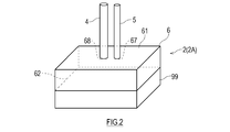
- FIG. 2 is a perspective view of the evaporator according to the first embodiment.
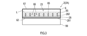
- FIG. 3 is a side view illustrating the internal structure of the evaporator shown in FIG.
- FIG. 4 is a plan view illustrating the internal structure of the evaporator shown in FIG.
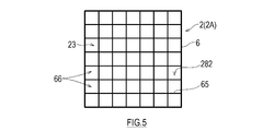
- FIG. 5 is a plan view illustrating the internal structure of the evaporator shown in FIG.
- FIG. 6 is a plan view illustrating a modified example of the internal structure of the evaporator shown in FIG.
- FIG. 7 is a figure explaining the height of a recessed part.
- FIG. 8 is a diagram showing a state in which the evaporator shown in FIG.
- FIG. 9 is a perspective view of the evaporator according to the second embodiment.
- FIG. 10 is a side view illustrating the internal structure of the evaporator shown in FIG.
- FIG. 11 is a diagram showing a state in which the evaporator shown in FIG. 9 is tilted.
- FIG. 1 is a diagram showing a schematic configuration of an aircraft 50 equipped with a loop heat pipe 10 according to an embodiment of the present invention.
- the loop heat pipe 10 shown in FIG. 1 includes an evaporator 2, a steam pipe 4, a condenser 3, and a liquid pipe 5 that form a closed loop.
- a working fluid which is a condensable fluid, is enclosed in the closed loop.
- the working fluid naturally circulates in the loop heat pipe 10 by utilizing phase change and gravity.
- the working fluid is not particularly limited, and is a condensable fluid that has been conventionally used as a working fluid for heat pipes (for example, water, alcohol, ammonia, fluorocarbon, hydrofluorocarbon, hydrofluoroether, and a mixed solution thereof). Etc.).
- the evaporator 2 is thermally connected to a heating element 99 which is a heat source.
- the liquid-phase working fluid absorbs heat from the heating element 99, and part of it boils and changes to gas.
- the gas-liquid two-phase working fluid moves to the condenser 3 through the steam pipe 4 which connects the outlet of the evaporator 2 and the inlet of the condenser 3 due to a pressure difference or buoyancy.
- the condenser 3 is installed above the evaporator 2.
- a cooling flow path (not shown) is formed in the condenser 3, and the two-phase working fluid radiates heat while passing through the cooling flow path and is cooled and changed to a liquid.
- the liquid-phase working fluid descends by gravity in the liquid pipe 5 that connects the outlet of the condenser 3 and the inlet of the evaporator 2, and returns to the evaporator 2.
- the loop type heat pipe 10 with the above configuration is mounted on a transport aircraft.
- transport aircraft examples include ships (including submersibles), railway vehicles, automobiles, and aircraft.
- the loop heat pipe 10 is mounted on an aircraft 50, which is an example of a transport aircraft.
- the aircraft 50 has a tilting allowance angle of ⁇ ° during normal operation, and is allowed to tilt within a range from horizontal to the tilting allowance angle during normal operation.
- FIG. 1 shows a part of the fuselage 51 and the main wing 53 of the aircraft 50.
- the body 51 has a multi-layer structure including an outer plate 52 and an inner wall 54 provided on the passenger side of the outer plate 52.
- a cooling chamber 55 is formed between the outer plate 52 and the inner wall 54.
- the inside of the cooling chamber 55 has a low temperature due to the cold heat transmitted from the outer plate 52 which is exposed to the outside air having a temperature significantly lower than that of the ground during flight.
- the outer plate 52 may be provided with an air inlet and an air outlet that communicate with the cooling chamber 55, and the outside air may be introduced into the cooling chamber 55 during flight.
- the condenser 3 is arranged in the cooling chamber 55, and the heating element 99 and the evaporator 2 thermally connected to the heating element 99 are arranged closer to the passenger compartment than the inner wall 54.
- a fan 56 for forcibly ventilating the condenser 3 is provided inside the cooling chamber 55.
- the working fluid is condensed by using the cold heat of the outside air.
- the heating element 99 is not particularly limited, but examples thereof include electronic devices including heating components such as a control panel, an engine control unit (ECU), and other computers, mechanical components that generate frictional heat such as bearings, and batteries. .. Further, instead of the heating element 99, cabin air may be used as a heat source.
- FIG. 2 is a perspective view of the evaporator 2A according to the first embodiment
- FIG. 3 is a side view illustrating an internal structure of the evaporator 2A shown in FIG. 2
- FIG. 4 is an inside of the evaporator 2A shown in FIG.
- FIG. 5 is a plan view illustrating the structure
- FIG. 5 is a plan view illustrating a modified example of the internal structure of the evaporator 2A illustrated in FIG. 2
- FIG. 6 is a view illustrating a state in which the evaporator 2A illustrated in FIG. 2 is inclined. ..
- the evaporator 2 ⁇ /b>A includes a housing 6, a heat receiving body 28 provided on a bottom surface 62 of the housing 6, and a wall provided inside the housing 6. And a member 65.
- the housing 6 has a rectangular parallelepiped shape with the maximum area of the top surface 61 and the bottom surface 62.
- a working fluid storage chamber 23 is formed inside the housing 6.
- a working fluid inlet 67 and a working fluid outlet 68, which communicate with the working fluid storage chamber 23, are provided in the central portion of the upper surface 61 of the housing 6, and the working fluid outlet 68 is connected to the steam pipe 4 and the working fluid.
- the liquid pipe 5 is connected to the inlet 67.
- the heat receiving body 28 is a plate-shaped member made of a metal material having a high thermal conductivity such as copper, and forms a part or all of the bottom surface 62 of the evaporator 2A.
- the heat receiving body 28 has a heat receiving surface 281 that appears outside the housing 6, and a boiling surface 282 that appears inside the working fluid storage chamber 23 in the housing 6.
- the boiling surface 282 forms the floor surface of the working fluid storage chamber 23.
- the heat receiving surface 281 is thermally connected to the heating element 99 arranged below the evaporator 2A and receives heat from the heating element 99.
- the wall member 65 is a plate-shaped member that is made of a metal material having a high thermal conductivity such as copper and stands up from the boiling surface 282 of the heat receiver 28 in the working fluid storage chamber 23.
- the material of the wall member 65 is not limited to the metal material.
- the wall member 65 may be in contact with the boiling surface 282 or may be joined to the boiling surface 282. Further, as shown in FIG. 4, the wall member 65 may be formed by digging out a plurality of recesses 66 from the heat transfer block that is in contact with the boiling surface 282.
- the wall member 65 divides the bottom of the working fluid storage chamber 23 into a plurality of sections, so that a plurality of recesses 66 are formed in the bottom of the working fluid storage chamber 23.
- the plurality of recesses 66 can capture the working fluid when the loop heat pipe 10 is tilted.
- the plurality of recesses 66 include a plurality of recesses 66 arranged in the tilting direction (tilt direction) of the transport machine.
- the wall member 65 may partition the bottom portion of the working fluid storage chamber 23 into a lattice shape.
- the wall member 65 may partition the bottom portion of the working fluid storage chamber 23 into a plurality of rectangular portions arranged in one direction.
- each recess 66 (that is, the height of the wall member 65) is equal to the "width 66w of the recess 66" which is the dimension of the recess 66 in the direction parallel to the inclination direction of the transport aircraft.
- the value is equal to or more than the value obtained by multiplying the “tangent of the tilting allowance angle ⁇ ” of the transport machine, and is equal to or less than the height Lh of the liquid level L of the working medium in the working fluid storage chamber. That is, the following expression (1) is established. [Width 66w of concave portion 66] ⁇ tan ⁇ [height 66h of concave portion 66] ⁇ [height Lh of liquid level L of working medium in working fluid storage chamber 23] (1)
- the wall member 65 when the boiling surface 282 is horizontal, the wall member 65 is lower than the liquid level L of the working fluid in the working fluid storage chamber 23, and the entire wall member 65 is below the liquid level L.
- the liquid level L of the working fluid when the hole that connects the recesses 66 adjacent to the wall member 65 is provided, the liquid level L of the working fluid may be lower than the height of the wall member 65.
- the heat received by the heat receiving body 28 from the heat generating body 99 is released from the boiling surface 282 and the wall member 65 to the working fluid. At least a part of the working fluid is boiled by its heat, and the portion above the liquid level L in the housing 6 is filled with the vapor phase or two-phase working fluid.
- the liquid level L does not exist strictly, but since the working fluid in the housing 6 has a larger volume ratio of the gas existing in the liquid as it goes upward, the working fluid in the gas-liquid two-phase flow increases.
- the liquid surface L may be virtually set.
- the evaporator 2A is an evaporator 2A that is mounted on a transportation machine and that changes at least a part of the liquid-phase working fluid into gas by receiving heat from the heating element 99.
- a housing 6 having at least one working fluid inlet 67 and at least one working fluid outlet 68, in which a working fluid housing chamber 23 for housing a working fluid is provided, and a bottom surface 62 of the housing 6.
- the heat receiving body 28 that is thermally connected to the heat generating body 99 and the bottom portion of the working fluid storage chamber 23 are partitioned into a plurality of recesses 66 that trap the working medium in the bottom portion of the working fluid storage chamber 23.
- a wall member 65 to be formed.
- the working fluid in the liquid phase in the working fluid storage chamber 23 is tilted at the bottom surface 62.
- the flow of the working fluid is blocked by the wall member 65, and the working fluid is trapped in the recess 66.
- the working fluid remains at the bottom of the working fluid storage chamber 23, and the heat receiving body 28 is entirely operated. Is maintained in contact with.
- the dry portion is dispersed with respect to the heating element 99 and is not unevenly distributed. Therefore, it is possible to efficiently cool the entire region of the heating element 99 in contact with the heat receiving surface 281 regardless of the change in the posture of the evaporator 2A.
- the bottom portion of the working fluid storage chamber 23 may be partitioned by the wall member 65 in a lattice shape.
- the wall member 65 can block the flow of the working fluid along the boiling surface 282 against the inclination of the evaporator 2A in all directions.
- the plurality of recesses 66 may include a plurality of recesses 66 arranged in the tilt direction of the transport machine.
- the height 66h of the concave portion 66 is tilted to the width 66w of the concave portion 66, which is the dimension of the concave portion 66 in the tilt direction of the transportation machine. It may be greater than or equal to the product of the tangent of the allowable angle ⁇ and less than or equal to the height Lh of the liquid level L of the working medium in the working fluid storage chamber 23.
- the height 66h of the recess 66 in this way, even if the evaporator 2A is tilted at an angle within the tilting allowable angle ⁇ of the transport machine, the boiling surface 282 of the heat receiving body 28 becomes a working fluid. The state of contact is maintained.
- ⁇ is a value that represents the tilting allowance angle that is allowed during normal operation of the transport aircraft equipped with the evaporator 2.
- the normal operation of a transportation machine is, for example, operation in consideration of economy and safety.
- ⁇ is not limited to the tilt allowable angle, and may be any one of the maximum value, the recommended value, and the average value of the tilt angle with respect to the horizontal when the transport device tilts.
- the range of the tilting movement of the transport aircraft during normal operation is different for each.
- the allowable pitch angle is about 15° and the allowable roll angle (bank angle) is about 30°.
- the allowable inclination angle with respect to the horizontal plane may be about 2 to 5°.
- the allowable pitch angle may be about 25° and the allowable roll angle may be 25°.
- the maximum inclination angle is about 20° (about 40%) on the road on which the automobile runs.
- the range of the tilting motion of the transportation machine is different, and an appropriate value of ⁇ may be set according to each transportation machine.
- the allowable tilt angle during normal operation is 30° or less, so the value of ⁇ may be set to 30 regardless of the range of the tilting motion of the transport aircraft.
- the value of ⁇ is not limited to the tilting allowance angle, and may be any one of the maximum value, the recommended value, and the average value of the tilting angle with respect to the horizontal when the transporting machine tilts.
- the loop heat pipe 10 includes an evaporator 2A that changes at least a part of a liquid-phase working fluid into a gas, a condenser 3 that changes a gas-phase working fluid into a liquid, and an evaporator.
- the steam pipe 4 connects the outlet of 2A and the inlet of the condenser 3
- the liquid pipe 5 connects the outlet of the condenser 3 and the inlet of the evaporator 2A.
- the boiling surface 282 is kept in contact with the working fluid. Therefore, in the loop heat pipe 10 including the evaporator 2A, the liquid phase from the heat receiver 28 is It is possible to suppress a decrease in the amount of heat transfer to the working fluid.
- FIG. 9 is a perspective view of the evaporator 2B according to the second embodiment
- FIG. 10 is a side view illustrating the internal structure of the evaporator 2B shown in FIG. 9
- FIG. 11 is a tilted view of the evaporator 2B shown in FIG. It is a figure which shows the appearance.
- the same or similar members as those in the first embodiment described above will be denoted by the same reference numerals in the drawings, and the description thereof will be omitted.
- an evaporator 2B has a casing 6 in which a top surface 61 and a bottom surface 62 have a rectangular parallelepiped shape with a maximum area, and a working fluid storage chamber 23 is provided therein.
- the heat receiving body 28 provided on the bottom surface 62 of the housing 6 and having the heat receiving surface 281 appearing outside the housing 6 and the boiling surface 282 appearing inside the working fluid storage chamber 23, and from the boiling surface 282 inside the working fluid storage chamber 23.
- a wall member 65 that stands up and divides the working fluid storage chamber 23 into a plurality of sections. 9 and 10, the evaporator 2B includes one common heat receiving body 28, but the heat receiving body 28 may be provided for each evaporator 2B.
- the wall member 65 extends from the boiling surface 282 to the ceiling of the working fluid storage chamber 23, and the wall member 65 separates the working fluid storage chamber 23 into a plurality of chambers (hereinafter, referred to as “evaporation unit 20”). ").
- the vapor pipe 4 and the liquid pipe 5 are connected to the upper surface 61 of each evaporating unit 20, and each evaporating unit 20 independently functions as an evaporator.
- the evaporator 2B having the above structure, as shown in FIG. 11, when the boiling surface 282 is inclined from the horizontal, the liquid-phase working fluid in the working fluid storage chamber 23 flows downward along the inclination of the boiling surface 282. As a result, a part of the boiling surface 282 is located above the liquid surface L of the working fluid and becomes a dry portion that is not in contact with the working fluid.
- the inside of the working fluid storage chamber 23 is divided into a plurality of evaporation portions 20, and a dry portion is generated in each evaporation portion 20, so that the dry portion is in contact with the heat receiving surface 281. Dispersed with respect to 99 and not unevenly distributed.
- the sum of the areas of the dry portions generated in each evaporation unit 20 is smaller than that in the case where the working fluid storage chamber 23 is not divided, and the reduction of the heat transfer amount from the heating element 99 to the evaporator 2 is suppressed. be able to.
- the evaporator 2B according to the present embodiment can be a constituent element of the loop heat pipe 10 like the evaporator 2A according to the first embodiment described above.
- the loop heat pipe 10 including the evaporator 2B similarly to the above, even if the posture is changed, it is possible to suppress a decrease in the amount of heat transfer from the heat receiver 28 to the liquid-phase working fluid. it can.
- the loop heat pipe 10 of the above embodiment is not limited to the thermosiphon type, but a wick type may be adopted.
- a wick type In the wick type loop heat pipe, in order to recirculate the working fluid from the condenser 3 to the evaporator 2, the capillary force of the working fluid in the wick is used, but gravity is also used. Therefore, even when the present invention is applied to the heat transport system including the wick type loop heat pipe, the same effect as described above can be obtained.
Landscapes
- Engineering & Computer Science (AREA)
- Physics & Mathematics (AREA)
- Thermal Sciences (AREA)
- Life Sciences & Earth Sciences (AREA)
- Sustainable Development (AREA)
- Mechanical Engineering (AREA)
- General Engineering & Computer Science (AREA)
- Microelectronics & Electronic Packaging (AREA)
- Cooling Or The Like Of Semiconductors Or Solid State Devices (AREA)
- Cooling Or The Like Of Electrical Apparatus (AREA)
Abstract
La présente invention concerne un évaporateur qui convertit au moins une partie d'un fluide de travail en phase liquide en un gaz en utilisant la chaleur d'un élément chauffant comprenant : un boîtier qui comporte au moins une entrée de fluide de travail et au moins une sortie de fluide de travail et est pourvu d'une chambre de réception de fluide de travail dans laquelle un fluide de travail est reçu; un élément de réception de chaleur disposé sur une surface inférieure du boîtier et relié thermiquement à l'élément chauffant; et un élément de paroi qui s'élève à partir d'une surface d'ébullition dans la chambre de réception de fluide de travail et divise le fond de la chambre de réception de fluide de travail en une pluralité de sections, formant ainsi une pluralité d'évidements pour capturer un milieu de travail au fond de la chambre de réception de fluide de travail.
Priority Applications (2)
| Application Number | Priority Date | Filing Date | Title |
|---|---|---|---|
| EP19906329.8A EP3905321A4 (fr) | 2018-12-27 | 2019-12-24 | Évaporateur et caloduc en boucle |
| US17/418,244 US20220034596A1 (en) | 2018-12-27 | 2019-12-24 | Evaporator and loop heat pipe |
Applications Claiming Priority (2)
| Application Number | Priority Date | Filing Date | Title |
|---|---|---|---|
| JP2018245274A JP2020106209A (ja) | 2018-12-27 | 2018-12-27 | 蒸発器及びループ型ヒートパイプ |
| JP2018-245274 | 2018-12-27 |
Publications (1)
| Publication Number | Publication Date |
|---|---|
| WO2020138081A1 true WO2020138081A1 (fr) | 2020-07-02 |
Family
ID=71125710
Family Applications (1)
| Application Number | Title | Priority Date | Filing Date |
|---|---|---|---|
| PCT/JP2019/050599 Ceased WO2020138081A1 (fr) | 2018-12-27 | 2019-12-24 | Évaporateur et caloduc en boucle |
Country Status (4)
| Country | Link |
|---|---|
| US (1) | US20220034596A1 (fr) |
| EP (1) | EP3905321A4 (fr) |
| JP (1) | JP2020106209A (fr) |
| WO (1) | WO2020138081A1 (fr) |
Cited By (2)
| Publication number | Priority date | Publication date | Assignee | Title |
|---|---|---|---|---|
| WO2021261552A1 (fr) * | 2020-06-24 | 2021-12-30 | 川崎重工業株式会社 | Évaporateur et caloduc en boucle |
| WO2022209359A1 (fr) * | 2021-04-01 | 2022-10-06 | 三菱重工業株式会社 | Système de refroidissement |
Families Citing this family (2)
| Publication number | Priority date | Publication date | Assignee | Title |
|---|---|---|---|---|
| JP7635586B2 (ja) | 2021-03-18 | 2025-02-26 | 富士電機株式会社 | 沸騰冷却装置 |
| WO2022259716A1 (fr) * | 2021-06-07 | 2022-12-15 | 株式会社村田製作所 | Dispositif de diffusion thermique |
Citations (5)
| Publication number | Priority date | Publication date | Assignee | Title |
|---|---|---|---|---|
| JPS5741354B1 (fr) | 1971-04-01 | 1982-09-02 | ||
| JP2004048489A (ja) * | 2002-07-12 | 2004-02-12 | Mitsubishi Electric Corp | 移動体搭載アンテナ及びその冷却装置 |
| JP2006114603A (ja) * | 2004-10-13 | 2006-04-27 | Toshiba Corp | 車両用半導体冷却装置 |
| JP2013032904A (ja) * | 2011-06-29 | 2013-02-14 | Panasonic Corp | 冷却装置およびこれを搭載した電子機器、および電気自動車 |
| DE102012111489A1 (de) * | 2012-11-27 | 2014-05-28 | Dr. Ing. H.C. F. Porsche Aktiengesellschaft | Kühlvorrichtung für eine Leistungselektronik zum Einsatz im Kraftfahrzeugbereich |
Family Cites Families (3)
| Publication number | Priority date | Publication date | Assignee | Title |
|---|---|---|---|---|
| WO2010058520A1 (fr) * | 2008-11-18 | 2010-05-27 | 日本電気株式会社 | Dispositif d'ébullition et de refroidissement |
| CN102834688B (zh) * | 2010-03-29 | 2015-07-15 | 日本电气株式会社 | 相变冷却器和设有该相变冷却器的电子设备 |
| JP6323051B2 (ja) * | 2014-02-19 | 2018-05-16 | 富士通株式会社 | 蒸発器、冷却装置、情報処理装置 |
-
2018
- 2018-12-27 JP JP2018245274A patent/JP2020106209A/ja active Pending
-
2019
- 2019-12-24 WO PCT/JP2019/050599 patent/WO2020138081A1/fr not_active Ceased
- 2019-12-24 US US17/418,244 patent/US20220034596A1/en not_active Abandoned
- 2019-12-24 EP EP19906329.8A patent/EP3905321A4/fr not_active Withdrawn
Patent Citations (5)
| Publication number | Priority date | Publication date | Assignee | Title |
|---|---|---|---|---|
| JPS5741354B1 (fr) | 1971-04-01 | 1982-09-02 | ||
| JP2004048489A (ja) * | 2002-07-12 | 2004-02-12 | Mitsubishi Electric Corp | 移動体搭載アンテナ及びその冷却装置 |
| JP2006114603A (ja) * | 2004-10-13 | 2006-04-27 | Toshiba Corp | 車両用半導体冷却装置 |
| JP2013032904A (ja) * | 2011-06-29 | 2013-02-14 | Panasonic Corp | 冷却装置およびこれを搭載した電子機器、および電気自動車 |
| DE102012111489A1 (de) * | 2012-11-27 | 2014-05-28 | Dr. Ing. H.C. F. Porsche Aktiengesellschaft | Kühlvorrichtung für eine Leistungselektronik zum Einsatz im Kraftfahrzeugbereich |
Non-Patent Citations (1)
| Title |
|---|
| See also references of EP3905321A4 |
Cited By (4)
| Publication number | Priority date | Publication date | Assignee | Title |
|---|---|---|---|---|
| WO2021261552A1 (fr) * | 2020-06-24 | 2021-12-30 | 川崎重工業株式会社 | Évaporateur et caloduc en boucle |
| WO2022209359A1 (fr) * | 2021-04-01 | 2022-10-06 | 三菱重工業株式会社 | Système de refroidissement |
| JP2022158103A (ja) * | 2021-04-01 | 2022-10-17 | 三菱重工業株式会社 | 冷却システム |
| US12501581B2 (en) | 2021-04-01 | 2025-12-16 | Mitsubishi Heavy Industries, Ltd. | Cooling system |
Also Published As
| Publication number | Publication date |
|---|---|
| EP3905321A4 (fr) | 2022-09-14 |
| JP2020106209A (ja) | 2020-07-09 |
| US20220034596A1 (en) | 2022-02-03 |
| EP3905321A1 (fr) | 2021-11-03 |
Similar Documents
| Publication | Publication Date | Title |
|---|---|---|
| WO2020138081A1 (fr) | Évaporateur et caloduc en boucle | |
| US10264706B2 (en) | Phase change evaporator with heat-dissipating fins and phase change cooling device using the same | |
| CN110753822B (zh) | 热虹吸器 | |
| WO2020138080A1 (fr) | Évaporateur et caloduc de type boucle | |
| JPWO2014157147A1 (ja) | 冷却装置 | |
| US20240251525A1 (en) | Ebullition cooling device | |
| JP2013245875A (ja) | 冷却装置及び電子装置 | |
| JPWO2018070116A1 (ja) | 冷却装置 | |
| JP2019052837A (ja) | 機器温調装置 | |
| EP4174937B1 (fr) | Évaporateur et caloduc en boucle | |
| WO2020138079A1 (fr) | Caloduc en boucle et dispositif de transport | |
| JP5860728B2 (ja) | 電子機器の冷却システム | |
| WO2020138078A1 (fr) | Caloduc à boucle et transporteur | |
| WO2019054076A1 (fr) | Appareil de réglage de température de dispositif | |
| JP2018105525A (ja) | 冷却装置およびこれを搭載した電子機器、および電気自動車 | |
| GB2225099A (en) | Boiling cooler | |
| WO2020138082A1 (fr) | Évaporateur et caloduc de type boucle | |
| JP7168850B2 (ja) | 蒸発器及び冷却システム | |
| JP4375124B2 (ja) | 半導体装置用の沸騰冷却装置 | |
| JP2005233526A (ja) | 冷却庫 | |
| JP2006269694A (ja) | 電力機器 | |
| WO2020138076A1 (fr) | Système de refroidissement de plaque extérieure | |
| JP2001339027A (ja) | 沸騰冷却装置 | |
| JP2018091496A (ja) | 冷却装置およびこれを搭載した電気自動車 |
Legal Events
| Date | Code | Title | Description |
|---|---|---|---|
| 121 | Ep: the epo has been informed by wipo that ep was designated in this application |
Ref document number: 19906329 Country of ref document: EP Kind code of ref document: A1 |
|
| NENP | Non-entry into the national phase |
Ref country code: DE |
|
| ENP | Entry into the national phase |
Ref document number: 2019906329 Country of ref document: EP Effective date: 20210727 |