WO2020141569A1 - サイリスタ起動装置 - Google Patents
サイリスタ起動装置 Download PDFInfo
- Publication number
- WO2020141569A1 WO2020141569A1 PCT/JP2019/000009 JP2019000009W WO2020141569A1 WO 2020141569 A1 WO2020141569 A1 WO 2020141569A1 JP 2019000009 W JP2019000009 W JP 2019000009W WO 2020141569 A1 WO2020141569 A1 WO 2020141569A1
- Authority
- WO
- WIPO (PCT)
- Prior art keywords
- synchronous machine
- rotation speed
- thyristor
- voltage
- angle
- Prior art date
- Legal status (The legal status is an assumption and is not a legal conclusion. Google has not performed a legal analysis and makes no representation as to the accuracy of the status listed.)
- Ceased
Links
Images


Classifications
-
- H—ELECTRICITY
- H02—GENERATION; CONVERSION OR DISTRIBUTION OF ELECTRIC POWER
- H02M—APPARATUS FOR CONVERSION BETWEEN AC AND AC, BETWEEN AC AND DC, OR BETWEEN DC AND DC, AND FOR USE WITH MAINS OR SIMILAR POWER SUPPLY SYSTEMS; CONVERSION OF DC OR AC INPUT POWER INTO SURGE OUTPUT POWER; CONTROL OR REGULATION THEREOF
- H02M5/00—Conversion of AC power input into AC power output, e.g. for change of voltage, for change of frequency, for change of number of phases
- H02M5/02—Conversion of AC power input into AC power output, e.g. for change of voltage, for change of frequency, for change of number of phases without intermediate conversion into DC
- H02M5/04—Conversion of AC power input into AC power output, e.g. for change of voltage, for change of frequency, for change of number of phases without intermediate conversion into DC by static converters
- H02M5/22—Conversion of AC power input into AC power output, e.g. for change of voltage, for change of frequency, for change of number of phases without intermediate conversion into DC by static converters using discharge tubes with control electrode or semiconductor devices with control electrode
- H02M5/25—Conversion of AC power input into AC power output, e.g. for change of voltage, for change of frequency, for change of number of phases without intermediate conversion into DC by static converters using discharge tubes with control electrode or semiconductor devices with control electrode using devices of a thyratron or thyristor type requiring extinguishing means
- H02M5/27—Conversion of AC power input into AC power output, e.g. for change of voltage, for change of frequency, for change of number of phases without intermediate conversion into DC by static converters using discharge tubes with control electrode or semiconductor devices with control electrode using devices of a thyratron or thyristor type requiring extinguishing means for conversion of frequency
- H02M5/272—Conversion of AC power input into AC power output, e.g. for change of voltage, for change of frequency, for change of number of phases without intermediate conversion into DC by static converters using discharge tubes with control electrode or semiconductor devices with control electrode using devices of a thyratron or thyristor type requiring extinguishing means for conversion of frequency for variable speed constant frequency systems
-
- H—ELECTRICITY
- H02—GENERATION; CONVERSION OR DISTRIBUTION OF ELECTRIC POWER
- H02M—APPARATUS FOR CONVERSION BETWEEN AC AND AC, BETWEEN AC AND DC, OR BETWEEN DC AND DC, AND FOR USE WITH MAINS OR SIMILAR POWER SUPPLY SYSTEMS; CONVERSION OF DC OR AC INPUT POWER INTO SURGE OUTPUT POWER; CONTROL OR REGULATION THEREOF
- H02M5/00—Conversion of AC power input into AC power output, e.g. for change of voltage, for change of frequency, for change of number of phases
- H02M5/02—Conversion of AC power input into AC power output, e.g. for change of voltage, for change of frequency, for change of number of phases without intermediate conversion into DC
- H02M5/04—Conversion of AC power input into AC power output, e.g. for change of voltage, for change of frequency, for change of number of phases without intermediate conversion into DC by static converters
- H02M5/22—Conversion of AC power input into AC power output, e.g. for change of voltage, for change of frequency, for change of number of phases without intermediate conversion into DC by static converters using discharge tubes with control electrode or semiconductor devices with control electrode
- H02M5/25—Conversion of AC power input into AC power output, e.g. for change of voltage, for change of frequency, for change of number of phases without intermediate conversion into DC by static converters using discharge tubes with control electrode or semiconductor devices with control electrode using devices of a thyratron or thyristor type requiring extinguishing means
- H02M5/27—Conversion of AC power input into AC power output, e.g. for change of voltage, for change of frequency, for change of number of phases without intermediate conversion into DC by static converters using discharge tubes with control electrode or semiconductor devices with control electrode using devices of a thyratron or thyristor type requiring extinguishing means for conversion of frequency
- H02M5/271—Conversion of AC power input into AC power output, e.g. for change of voltage, for change of frequency, for change of number of phases without intermediate conversion into DC by static converters using discharge tubes with control electrode or semiconductor devices with control electrode using devices of a thyratron or thyristor type requiring extinguishing means for conversion of frequency from a three phase input voltage
-
- H—ELECTRICITY
- H02—GENERATION; CONVERSION OR DISTRIBUTION OF ELECTRIC POWER
- H02M—APPARATUS FOR CONVERSION BETWEEN AC AND AC, BETWEEN AC AND DC, OR BETWEEN DC AND DC, AND FOR USE WITH MAINS OR SIMILAR POWER SUPPLY SYSTEMS; CONVERSION OF DC OR AC INPUT POWER INTO SURGE OUTPUT POWER; CONTROL OR REGULATION THEREOF
- H02M7/00—Conversion of AC power input into DC power output; Conversion of DC power input into AC power output
- H02M7/42—Conversion of DC power input into AC power output without possibility of reversal
- H02M7/44—Conversion of DC power input into AC power output without possibility of reversal by static converters
- H02M7/48—Conversion of DC power input into AC power output without possibility of reversal by static converters using discharge tubes with control electrode or semiconductor devices with control electrode
-
- H—ELECTRICITY
- H02—GENERATION; CONVERSION OR DISTRIBUTION OF ELECTRIC POWER
- H02P—CONTROL OR REGULATION OF ELECTRIC MOTORS, ELECTRIC GENERATORS OR DYNAMO-ELECTRIC CONVERTERS; CONTROLLING TRANSFORMERS, REACTORS OR CHOKE COILS
- H02P1/00—Arrangements for starting electric motors or dynamo-electric converters
- H02P1/16—Arrangements for starting electric motors or dynamo-electric converters for starting dynamo-electric motors or dynamo-electric converters
- H02P1/46—Arrangements for starting electric motors or dynamo-electric converters for starting dynamo-electric motors or dynamo-electric converters for starting an individual synchronous motor
-
- H—ELECTRICITY
- H02—GENERATION; CONVERSION OR DISTRIBUTION OF ELECTRIC POWER
- H02P—CONTROL OR REGULATION OF ELECTRIC MOTORS, ELECTRIC GENERATORS OR DYNAMO-ELECTRIC CONVERTERS; CONTROLLING TRANSFORMERS, REACTORS OR CHOKE COILS
- H02P27/00—Arrangements or methods for the control of AC motors characterised by the kind of supply voltage
- H02P27/04—Arrangements or methods for the control of AC motors characterised by the kind of supply voltage using variable-frequency supply voltage, e.g. inverter or converter supply voltage
- H02P27/06—Arrangements or methods for the control of AC motors characterised by the kind of supply voltage using variable-frequency supply voltage, e.g. inverter or converter supply voltage using DC to AC converters or inverters
-
- H—ELECTRICITY
- H02—GENERATION; CONVERSION OR DISTRIBUTION OF ELECTRIC POWER
- H02P—CONTROL OR REGULATION OF ELECTRIC MOTORS, ELECTRIC GENERATORS OR DYNAMO-ELECTRIC CONVERTERS; CONTROLLING TRANSFORMERS, REACTORS OR CHOKE COILS
- H02P6/00—Arrangements for controlling synchronous motors or other dynamo-electric motors using electronic commutation dependent on the rotor position; Electronic commutators therefor
- H02P6/20—Arrangements for starting
-
- H—ELECTRICITY
- H02—GENERATION; CONVERSION OR DISTRIBUTION OF ELECTRIC POWER
- H02P—CONTROL OR REGULATION OF ELECTRIC MOTORS, ELECTRIC GENERATORS OR DYNAMO-ELECTRIC CONVERTERS; CONTROLLING TRANSFORMERS, REACTORS OR CHOKE COILS
- H02P2101/00—Special adaptation of control arrangements for generators
- H02P2101/20—Special adaptation of control arrangements for generators for steam-driven turbines
-
- H—ELECTRICITY
- H02—GENERATION; CONVERSION OR DISTRIBUTION OF ELECTRIC POWER
- H02P—CONTROL OR REGULATION OF ELECTRIC MOTORS, ELECTRIC GENERATORS OR DYNAMO-ELECTRIC CONVERTERS; CONTROLLING TRANSFORMERS, REACTORS OR CHOKE COILS
- H02P2207/00—Indexing scheme relating to controlling arrangements characterised by the type of motor
- H02P2207/05—Synchronous machines, e.g. with permanent magnets or DC excitation
Definitions
- This invention relates to a thyristor starter.
- a thyristor starter for starting a synchronous machine such as a generator and an electric motor has been developed (see, for example, International Publication No. 2014/033849 (Patent Document 1)).
- the thyristor starter is a converter that converts AC power into DC power, a DC reactor that smoothes DC power, and DC power that is supplied from the converter via the DC reactor into AC power with a variable frequency to create a synchronous machine.
- an inverter for supplying. By controlling the AC power supplied to the synchronous machine, the stopped synchronous machine can be started and driven at a predetermined rotation speed.
- the inverter has at least 6 thyristors.
- the inverter can supply three-phase AC power to the synchronous machine to increase the rotational speed of the synchronous machine by sequentially firing the two six thyristors in synchronization with the rotation of the synchronous machine.
- the reverse bias period of the thyristor is the difference between the control advance angle and the commutation overlap angle.
- the thyristor reverse bias period must be longer than the angle corresponding to the thyristor turn-off time.
- the difference between the control lead angle and the commutation overlap angle is also called the commutation allowance angle, and the period corresponding to the commutation allowance angle is also called the commutation allowance time.
- the commutation margin time becomes shorter as the rotation speed of the synchronous machine increases. Therefore, there is a concern that commutation of the thyristor may fail in the high rotation speed region of the synchronous machine.
- the present invention has been made to solve the above problems, and an object thereof is to ensure a commutation of a thyristor in a high rotation speed region of a synchronous machine in a thyristor starter that starts a synchronous machine. To do.
- the converter converts AC power into DC power.
- the DC reactor smoothes DC power.
- the inverter converts DC power supplied from the converter via the DC reactor into AC power of variable frequency and supplies the AC power to the synchronous machine.
- the control unit is configured to control the inverter based on the phase control angle.
- the voltage regulator is configured to regulate the induced voltage of the synchronous machine by supplying a field current to the synchronous machine.
- the voltage adjustment device controls the field current so that the induced voltage increases as the rotational speed of the synchronous machine increases.
- the control unit reduces the increase rate of the phase control angle with respect to the rotation speed of the synchronous machine, as compared with the case where the rotation speed of the synchronous machine is less than the reference rotation speed.
- the commutation of the thyristor in the high rotation speed region of the synchronous machine can be reliably performed.
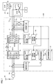
- FIG. 1 is a schematic configuration diagram of a thyristor starting device according to an embodiment of the present invention.
- the thyristor starter 100 accelerates the stopped synchronous machine 20 to the synchronous speed, determines the synchronous state between the synchronous machine voltage and the voltage of the system to which the synchronous machine 20 is connected, and synchronizes.
- the machine 20 is connected to the power system. Simultaneously with the insertion, the thyristor starter 100 is disconnected from the synchronous machine 20.
- the thyristor starting device 100 is also called a static frequency converter (SFC).
- SFC static frequency converter
- the thyristor starting device 100 during acceleration operates as a variable speed drive device by a separately excited inverter that commutates the current flowing through the thyristor by utilizing the counter electromotive force of the synchronous machine 20.
- the synchronous machine 20 has a stator having armature windings ATU, ATV, ATW, and a field winding 22.
- the synchronous machine 20 is coupled to, for example, a gas turbine GT of a thermal power plant, and is rotationally driven by the gas turbine GT.
- Thyristor starter 100 is connected to the secondary side of transformer TR.
- the primary side of the transformer TR is connected to the AC power supply 30.
- the transformer TR converts the three-phase AC voltage supplied from the AC power supply 30 into the three-phase AC voltage having a predetermined voltage value and supplies the three-phase AC voltage having a predetermined voltage value to the thyristor starter 100.
- the thyristor starter 100 includes a converter 1, a DC reactor 3, an inverter 2, and an AVR (automatic voltage regulator) 21.
- the converter 1 is a three-phase full-wave rectifier having at least six thyristors, and converts the three-phase AC power from the transformer TR into variable-voltage DC power.
- the DC reactor 3 is connected between the positive side output terminal 1a of the converter 1 and the positive side input terminal 2a of the inverter 2.
- the DC reactor 3 smoothes the DC output current Id of the converter 1.
- the negative output terminal 1b of the converter 1 and the negative input terminal 2b of the inverter 2 are connected to each other. Note that another DC reactor may be connected between the negative output terminal 1b of converter 1 and the negative input terminal 2b of inverter 2.
- the three output terminals 2c, 2d, 2e of the inverter 2 are connected to the three armature windings ATU, ATV, ATW of the synchronous machine 20, respectively.
- the inverter 2 is a three-phase separately excited inverter having at least 6 thyristors U, V, W, X, Y, and Z.
- the inverter 2 converts the DC power supplied from the converter 1 via the DC reactor 3 into AC power having a variable frequency and supplies the AC power to the synchronous machine 20.
- the AVR 21 supplies the field current If to the field winding 22 of the synchronous machine 20.
- the AVR 21 controls the field current If supplied to the field winding 22 so that the AC voltage output from the synchronous machine 20 is kept constant regardless of the rotation speed of the gas turbine.
- the AC power is supplied from the inverter 2 to the armature windings ATU, ATV, ATV, whereby the rotation of the synchronous machine 20 is accelerated.
- the AVR 21 corresponds to an example of “voltage regulator”.
- the thyristor starter 100 further includes current transformers 4 and 5, a voltage detector 6, a position detector 7, a current detector 9, an inverter controller 10, and a converter controller 13.
- the current transformer 4 detects a three-phase alternating current flowing from the transformer TR to the converter 1 and gives a signal indicating the detected value to the current detector 9.
- the current detector 9 calculates the DC current Id output from the converter 1 based on the signal from the current transformer 4, and gives a signal indicating the calculated value to the converter control unit 13.
- the current detector 9 has a full-wave rectification type diode rectifier, and converts the detected three-phase alternating current into a direct current Id.
- the current transformer 5 detects the current flowing from the inverter 2 to the armature windings ATU, ATV, ATW of the synchronous machine 20 and gives a signal indicating the detected value to the position detector 7.
- the voltage detector 6 detects the instantaneous value of the three-phase AC voltage Vu, Vv, Vw supplied from the inverter 2 to the synchronous machine 20, and gives a signal indicating the detected value to the position detector 7. Specifically, the voltage detector 6 uses two line voltages (U-phase-V in FIG. 1) of the line voltages of the three-phase AC voltage in the armature windings ATU, ATV, ATW of the synchronous machine 20. The interphase AC voltage Vu-v and the V phase-W phase AC voltage Vv-w) are detected.
- the position detector 7 detects the position of the rotor of the synchronous machine 20 based on the signals from the current transformer 5 and the voltage detector 6, and gives a signal indicating the detected value to the inverter controller 10 and the converter controller 13. ..
- the inverter control unit 10 controls the ignition phase of the inverter 2 based on the signal from the position detector 7. Specifically, the inverter controller 10 includes a control angle calculator 11 and a gate pulse generator 12.
- the control angle calculation unit 11 calculates the phase control angle ⁇ 0 based on the detected position of the rotor of the synchronous machine 20, and supplies the calculated phase control angle ⁇ 0 to the gate pulse generator 12. Specifically, when the control angle calculation unit 11 calculates the rotation speed of the synchronous machine 20 based on the signal from the position detector 7, the control angle calculation unit 11 sets the phase control angle ⁇ 0 based on the calculated rotation speed.
- the phase control angle ⁇ 0 is set so that the phase of the output phase current of the inverter 2 advances with respect to the induced voltage inside the synchronous machine 20.
- the actual advance angle ⁇ becomes smaller than the phase control angle ⁇ 0 as the phase current increases.
- the phase control angle ⁇ 0 is also referred to as “setting control advance angle ⁇ 0 ”
- the actual advance angle ⁇ is also referred to as “effective control advance angle ⁇ ”.
- the control angle calculator 11 may calculate the rotation speed of the synchronous machine 20 based on the signal from the voltage detector 6 instead of the position detector 7.
- the gate pulse generator 12 generates a gate pulse (firing command) to be given to the gate of the thyristor of the inverter 2 based on the setting control advance angle ⁇ 0 received from the control angle calculation unit 11.
- the inverter control unit 10 corresponds to an example of “control unit”.
- the converter control unit 13 controls the ignition phase of the converter 1 based on the signal from the position detector 7 and the signal from the current detector 9. Specifically, converter control unit 13 controls the ignition phase of converter 1 so that DC current Id output from converter 1 matches current command value Id*.
- the converter control unit 13 includes a speed control unit 14, a current control unit 15, a control angle calculation unit 16, and a gate pulse generator 17.
- the speed control unit 14 calculates the rotation speed of the synchronous machine 20 based on the detected position of the rotor of the synchronous machine 20.
- the speed control unit 14 generates a current command value Id* which is a target value of the direct current Id based on the calculated rotation speed.
- the current control unit 15 calculates the deviation ⁇ Id between the current command value Id* and the direct current Id, and generates the voltage command value VDC1* based on the calculated deviation ⁇ Id.
- the current control unit 15 includes a proportional element (P:proportional element), an integral element (I:integral element), and an addition unit.
- the proportional element multiplies the deviation ⁇ Id by a predetermined proportional gain and outputs it to the addition section, and the integral element integrates the deviation ⁇ Id with a predetermined integration gain and outputs it to the addition section.
- the adder adds the outputs from the proportional element and the integral element to generate a voltage command value VDC1*.
- Voltage command value VDC1* corresponds to a control command defining DC voltage VDC1 that converter 1 should output.
- the converter 1 controls the DC voltage VDC1 so that it is larger than the DC voltage VDC2 on the input terminal side of the inverter 2 by the voltage drop due to the DC reactor 3. Thereby, the direct current Id is controlled.
- the control angle calculation unit 16 calculates the phase control angle ⁇ based on the voltage command value VDC1* given from the current control unit 15.
- the control angle calculation unit 16 gives the calculated phase control angle ⁇ to the gate pulse generator 17.
- the gate pulse generator 17 generates a gate pulse (firing command) to be given to the gate of the thyristor of the converter 1 based on the phase control angle ⁇ received from the control angle calculation unit 16.
- the converter 1 is switching-controlled according to the gate pulse generated by the gate pulse generator 17, so that the converter 1 outputs the DC current Id according to the current command value Id*.
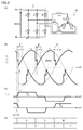
- FIG. 2 is a time chart schematically showing the commutation operation of the inverter 2.
- FIG. 2A is a circuit diagram showing the current that actually flows in the inverter 2.
- the synchronous machine 20 has three-phase inductance components Lu, Lv, Lw.
- FIG. 2B shows terminal voltages (three-phase AC voltages) Vu, Vv, Vw of the synchronous machine 20 and a DC voltage VDC2 appearing between the input terminals 2a, 2b of the inverter 2.
- FIG. 2C shows currents iw and iu flowing in the inverter 2.
- FIG. 2D shows a conducting thyristor of the six thyristors U, V, W, X, Y, and Z of the inverter 2.
- an ignition command is given to a predetermined thyristor at the time when the phase is advanced by a desired angle from the reference point. For example, a gate pulse is given to the thyristor V while the thyristor U is conducting, and then a gate pulse is given to the thyristor W while the thyristor V is conducting. Similarly, a gate pulse is applied to thyristor X while thyristor Z is conducting, and a gate pulse is applied to thyristor Y while thyristor X is next conducting.
- the line voltages Vu-v, Vv-w, and Vw-u of the synchronous machine 20 sequentially appear as a DC voltage VDC2 between the input terminals 2a and 2b of the inverter 2 according to the transition of the conducting thyristor.
- the inverter control unit 10 controls the path of the current flowing through the synchronous machine 20 by firing the six thyristors U, V, W, X, Y, and Z in sequence in sequence according to the rotation of the synchronous machine 20. can do.
- the thyristor reverse bias period must be longer than the angle corresponding to the thyristor turn-off time.
- This ⁇ is also called “commutation allowance angle”
- the period corresponding to the commutation allowance angle is also called “commutation allowance time”. If the turn-off time of the thyristor is t off , the commutation allowance angle ⁇ must be ⁇ t off or more.
- FIG. 3 is a time chart showing the basic operation of the thyristor starting device 100.
- FIG. 3 shows the rotation speed of the synchronous machine 20, the effective value of the terminal voltage of the synchronous machine 20, the field current, the set control lead angle, and the commutation margin time of the thyristor in the inverter 2.
- the thyristor starter 100 When the thyristor starter 100 is activated at time t1, the thyristor starter 100 accelerates the synchronous machine 20 from a completely stopped state to a predetermined rotation speed Na.
- a constant field magnetic flux If is generated in the rotor of the synchronous machine 20 by the constant field current If.
- the AVR 21 keeps the field current If supplied to the field winding 22 constant while the rotation speed of the synchronous machine 20 is constant. Keep at value.
- the setting control advance angle ⁇ 0 is maintained at a constant value ⁇ a regardless of changes in the rotation speed while the rotation speed of the synchronous machine 20 is from 0 to a predetermined rotation speed Na.
- the effective value of the terminal voltage of the synchronous machine 20 increases linearly from 0V to VC.
- the rotation speed Na is set to, for example, about 20% of the rated speed of the gas turbine GT.
- the AVR 21 reduces the field current If supplied to the field winding 22. As a result, the effective value of the terminal voltage of the synchronous machine 20 is maintained at the constant voltage VC even if the rotation speed changes.
- the set control advance angle ⁇ 0 linearly increases from the minimum value ⁇ a to the maximum value ⁇ b at a constant increase rate according to the rotation speed.
- the rate of increase in the setting control lead angle beta 0 represents the ratio of the increment [Delta] [beta] 0 of the rotational speed N increase .DELTA.N setting control advance angle beta 0 for the synchronous machine 20 ( ⁇ 0 / ⁇ N).
- the setting control advance angle ⁇ 0 is linearly increased at a constant rate of increase in accordance with the increase in the rotation speed, so that the setting control advance angle ⁇ 0 is set regardless of the change in the rotation speed. It is possible to suppress the rise of the DC voltage VDC2 during the commutation overlap period, as compared with the case where the configuration is constant.
- the setting control advance angle ⁇ 0 is maintained at the maximum value ⁇ b.
- the rotation speed Nb is set to about 70% of the rated speed of the gas turbine GT, for example.
- the commutation margin time gradually decreases after the time t1 due to the increase in the commutation overlap period according to the rotation speed of the synchronous machine 20.
- the commutation margin time becomes shorter as the rotation speed of the synchronous machine 20 increases.
- the commutation margin time has a threshold time Tth at which the thyristor cannot commutate. This threshold time Tth is determined by the turn-off time t off of the thyristor. In the example of FIG. 3, the commutation margin time is shorter than the threshold time Tth before time t4. Therefore, there is concern that the thyristor may fall into commutation failure.
- the thyristor starter 100 provides a control configuration of the thyristor starter 100 that can secure the commutation margin time of the inverter 2 even when the rotation speed of the synchronous machine 20 becomes high. To do.
- the voltage and current of the inverter 2 and the synchronous machine 20 are defined as shown in FIG.
- Id represents a current flowing in the DC reactor 3
- Ed is a DC voltage between the input terminals 2a and 2b of the inverter 2 (corresponding to VDC2 in FIG. 1).
- Indicates. Iu represents the U-phase current of the three-phase AC current output by the inverter 2
- Eu represents the U-phase voltage of the three-phase AC voltage output by the inverter 2.
- Z indicates the impedance of one phase of the synchronous machine 20
- Ea indicates the induced voltage generated inside the synchronous machine 20. Note that, for Z, for simplicity of explanation, it is assumed that the resistance component in the impedance for one phase is sufficiently small and is ignored, and only the reactance X is included.
- FIG. 5A is a vector diagram drawn based on the U-phase voltage Eu of the thyristor starter 100. As shown in FIG. 5A, the U-phase current Iu of the inverter 2 leads the U-phase voltage Eu of the inverter 2 by the phase angle ⁇ . The phase angle ⁇ is the power factor angle.
- the induced voltage Ea inside the synchronous machine 20 in operation is delayed by the phase angle ⁇ with respect to the U-phase voltage Eu.
- the phase angle ⁇ is the load angle.
- Z ⁇ Iu has a magnitude of product X ⁇ Iu of reactance X and U-phase current Iu, and has a phase difference of ⁇ /2 with Iu.
- the current waveform becomes trapezoidal due to the commutation overlap angle u, and the phase of Iu is delayed by u/2 in terms of phase.
- phase angle ⁇ 0 ⁇ obtained by subtracting the load angle ⁇ from the set control advance angle ⁇ 0 becomes the effective control advance angle ⁇ .
- phase angle ⁇ -u/2 obtained by subtracting u/2 from the effective control advance angle ⁇ becomes the power factor angle ⁇ .
- the commutation margin time corresponding to the commutation margin angle ⁇ becomes shorter, so that the thyristor may cause commutation failure.
- K is a constant
- ⁇ is a synthetic magnetic flux
- ⁇ is an angular velocity.
- the vector diagram of FIG. 5(B) has the same rotation speed of the synchronous machine 20 as the vector diagram of FIG. 5(A).
- the setting control advance angle ⁇ 0 has the same magnitude as that of FIG. 5A.
- the phase currents Iu and Z ⁇ Iu are also the same in FIGS. 5A and 5B.
- the U-phase voltage Eu is also increased by increasing the induced voltage Ea without changing the magnitude of Z ⁇ Iu.
- the commutation overlapping angle u decreases as the U-phase voltage Eu output from the inverter 2 increases. Therefore, in FIG. 5B, the commutation overlapping angle u is smaller than that in FIG. 5A.
- the power factor angle ⁇ increases as the effective control advance angle ⁇ increases.
- An increase in the power factor angle ⁇ causes a decrease in the output power of the thyristor starter 100.
- the DC voltage Ed is given by the following equation (6).
- the expression (6) can be rewritten as the following expression (7) using the expression (4).
- the output power of the inverter 2 is equal to the input power of the inverter 2 according to the law of conservation of energy, and thus can be represented by the product Ed ⁇ Id of the DC voltage Ed and the DC current Id. According to the equation (7), the DC voltage Ed becomes smaller as the power factor angle ⁇ becomes larger, so that the output power of the inverter 2 may be lowered.
- the set control angle ⁇ 0 is reduced within a range in which the commutation margin angle ⁇ can be secured as the induced voltage Ea of the synchronous machine 20 increases. .. This suppresses the decrease in the DC voltage Ed due to the increase in the power factor angle ⁇ .
- the rotation speed of the synchronous machine 20 is the same as that of the vector diagrams of FIGS. 5A and 5B.
- the induced voltage Ea of the synchronous machine 20 has the same magnitude as that of FIG. 5B.
- the U-phase currents Iu and Z ⁇ Iu of the inverter 2 are also set to have the same magnitude as in FIG. 5(B).
- the setting control advance angle ⁇ 0 is made smaller than that in FIG. 5(B).
- the commutation margin angle ⁇ is .omega.t off more (t off the turn-off time of the thyristor) it is necessary to adjust the the setting control advance angle beta 0 within an amount.
- the DC voltage Ed will be kept at a constant value. be able to. Therefore, it is preferable to adjust the set control angle ⁇ 0 according to the rotation speed of the synchronous machine 20 so that ⁇ toff and Eu ⁇ cos ⁇ is constant. According to this, it is possible to suppress the decrease of the DC voltage Ed (that is, the decrease of the output power of the thyristor starter 100) while ensuring the commutation margin time.
- FIG. 6 is a time chart showing the operation of thyristor starter 100 according to the present embodiment.
- FIG. 6 shows the rotation speed of the synchronous machine 20, the effective value of the terminal voltage of the synchronous machine 20, the field current, the setting control advance angle, and the commutation margin time.
- the waveform of the rotation speed of the synchronous machine 20 shown in FIG. 6 is the same as that shown in the basic operation of FIG.
- the waveforms of the effective value of the terminal voltage, the field current, the setting control advance angle, and the commutation margin time of the synchronous machine 20 shown in FIG. 3 are indicated by broken lines.
- the time chart of FIG. 6 differs from the time chart of FIG. 3 in the waveforms of the effective value of the terminal voltage, the field current, the set control lead angle, and the commutation margin time after time t3.
- the gas turbine GT is ignited at time t3
- the synchronous machine 20 starts to accelerate.
- the rotational speed of the synchronous machine 20 reaches the preset reference rotational speed Nc at time t5
- the AVR 21 controls the field current If supplied to the field winding 22 of the synchronous machine 20 to thereby cause the synchronous machine 20 to operate.
- the effective value of the induced voltage Ea of 20 is increased.
- Na ⁇ Nc ⁇ Nb Na ⁇ Nc ⁇ Nb.
- the AVR 21 controls the field current If so that the effective value of the induced voltage increases as the rotation speed of the synchronous machine 20 increases.
- the field current If is maintained at the constant value If1.
- the effective value of the terminal voltage of the synchronous machine 20 gradually increases from VC.
- the reference rotation speed Nc is a commutation margin time when the set control advance angle ⁇ 0 is increased from ⁇ a according to the rotation speed while maintaining the effective value of the terminal voltage of the synchronous machine 20 at a constant value VC. Is set to the rotation speed when becomes larger than the threshold time Tth.
- the commutation allowance time becomes shorter as the rotation speed of the synchronous machine 20 increases after time t3.
- time t5 by increasing the induced voltage of the synchronous machine 20 as the rotation speed of the synchronous machine 20 increases, the effective control advance angle ⁇ increases and the decrease of the commutation margin time is suppressed.
- the set control advance angle ⁇ 0 is constant, the power factor angle ⁇ increases together with the effective control advance angle ⁇ , so the output power of the thyristor starter 100 decreases. There is a concern that it will end up.
- the thyristor starting device 100 reduces the increase rate ⁇ 0 / ⁇ N of the set control advance angle ⁇ 0 on condition that the commutation margin time becomes longer than the threshold time Tth.
- the control angle calculation unit 11 compares the increase rate ⁇ 0 / ⁇ N of the set control advance angle ⁇ 0 with the rotational speed of the synchronous machine 20 between Na and Nc.
- the increase rate ⁇ 0 / ⁇ N of the setting control advance angle ⁇ 0 is reduced when the speed is between Nc and Nb. According to this, when attention is paid to the waveform of the setting control advance angle beta 0 after time t5, in FIG. 6 (solid line), compared FIG 3 (dashed line), setting control advance angle beta 0 for the same rotational speed is reduced ing.
- the setting control advance angle ⁇ 0 linearly increases at a constant increase rate ⁇ 0 / ⁇ N according to the rotation speed.
- the increase rate ⁇ 0 / ⁇ N of the setting control advance angle ⁇ 0 may be changed a plurality of times depending on the rotation speed while the rotation speed is from Nc to Nb.
- the increase rate ⁇ 0 / ⁇ N of the setting control advance angle ⁇ 0 may be reduced stepwise according to the rotation speed.
- the setting control angle ⁇ 0 should be set based on the terminal voltage so that the product of the terminal voltage (phase voltage Eu) of the synchronous machine 20 and cos ⁇ becomes a constant value.
- the DC voltage (corresponding to VDC2 in FIG. 1) appearing between the input terminals 2a and 2b of the inverter 2 can be maintained at a constant value regardless of the rotation speed of the synchronous machine 20.
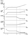
- FIG. 7 is a diagram showing an example of the relationship between the rotation speed of the synchronous machine 20 and the field current If.
- the vertical axis of FIG. 7 represents the field current If
- the horizontal axis represents the rotation speed of the synchronous machine 20.
- the field current If decreases between the rotation speed Na and the reference rotation speed Nc according to the rotation speed. When the rotation speed exceeds the reference rotation speed Nc, the field current If is maintained at a constant value If1.
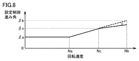
- FIG. 8 is a diagram showing an example of the relationship between the rotation speed of the synchronous machine 20 and the setting control advance angle ⁇ 0 .
- the broken line in the figure shows the relationship between the rotation speed of the synchronous machine 20 shown in FIG. 3 and the setting control advance angle ⁇ 0 .
- the set control advance angle ⁇ 0 linearly increases from ⁇ a to ⁇ c at the first increase rate ⁇ 0 / ⁇ N according to the rotation speed. While the rotation speed is between the reference rotation speeds Nc and Nb, the setting control advance angle ⁇ 0 linearly increases from ⁇ c to ⁇ b at the second increase rate ⁇ 0 / ⁇ N according to the rotation speed. However, the second rate of increase is smaller than the first rate of increase.
- the AVR 21 and the inverter control unit 10 refer to the map or the relational expression based on the rotation speed of the synchronous machine 20 to refer to the field current. If and the setting control advance angle ⁇ 0 can be set respectively.
- the thyristor starter in the high rotation speed region of the synchronous machine, the induced voltage of the synchronous machine is increased as the rotation speed of the synchronous machine is increased, and the low rotation speed is increased.
- the increase rate of the setting control advance angle in the inverter as compared with the speed range, it is possible to secure a commutation margin time of the thyristor in the inverter while suppressing a decrease in output power of the thyristor starter.
- the adjustment of the induced voltage and the setting control advance angle described above is performed only in the high rotation speed region where the commutation margin time is short, so that the accident current is large and the thyristor It does not affect the low rotation speed region where overcurrent withstand capability is a concern. Furthermore, since the DC voltage Ed can be maintained at a constant value, it is possible to avoid affecting the converter 1.
- the synchronous machine 20 demonstrated the case where it was a generator rotationally driven by the gas turbine in a thermal power plant, it is not restricted to this,
- the synchronous machine 20 is used in a general industrial field. It may be a synchronized machine.
Landscapes
- Engineering & Computer Science (AREA)
- Power Engineering (AREA)
- Control Of Eletrric Generators (AREA)
- Control Of Ac Motors In General (AREA)
Abstract
Description
図1を参照して、サイリスタ起動装置100は、停止している同期機20を同期速度まで加速し、同期機電圧と同期機20が接続される系統の電圧との同期状態を判定して同期機20を電力系統に併入するものである。併入と同時に、サイリスタ起動装置100は同期機20から切り離される。サイリスタ起動装置100は、静止形周波数変換装置(SFC:Static Frequency Converter)とも呼ばれる。加速中のサイリスタ起動装置100は、同期機20の逆起電力を利用してサイリスタに流れる電流を転流する他励式インバータによる可変速駆動装置として動作する。
図2は、インバータ2の転流動作を模式的に示すタイムチャートである。図2(A)は、インバータ2に実際に流れる電流を示す回路図である。同期機20は3相のインダクタンス成分Lu,Lv,Lwを有している。図2(B)は、同期機20の端子電圧(三相交流電圧)Vu,Vv,Vw、およびインバータ2の入力端子2a,2b間に現れる直流電圧VDC2を示している。図2(C)は、インバータ2に流れる電流iw,iuを示している。図2(D)は、インバータ2の6個のサイリスタU,V,W,X,Y,Zのうちの導通しているサイリスタを示している。
図3は、サイリスタ起動装置100の基本動作を示すタイムチャートである。図3には、同期機20の回転速度、同期機20の端子電圧の実効値、界磁電流、設定制御進み角、およびインバータ2におけるサイリスタの転流余裕時間が示されている。


Claims (4)
- 同期機を起動させるサイリスタ起動装置であって、
交流電力を直流電力に変換するコンバータと、
前記直流電力を平滑化する直流リアクトルと、
前記コンバータから前記直流リアクトルを介して与えられる前記直流電力を可変周波数の交流電力に変換して前記同期機に供給するインバータと、
位相制御角に基づいて前記インバータを制御するように構成された制御部と、
前記同期機に界磁電流を供給することにより前記同期機の誘起電圧を調整するように構成された電圧調整装置とを備え、
前記同期機の加速中に前記同期機の回転速度が基準回転速度を超えると、
前記電圧調整装置は、前記同期機の回転速度の上昇に従って前記誘起電圧が増加するように前記界磁電流を制御し、かつ、
前記制御部は、前記同期機の回転速度が前記基準回転速度未満のときと比較して、前記同期機の回転速度に対する前記位相制御角の増加率を減少させる、サイリスタ起動装置。 - 前記同期機の加速中に前記同期機の回転速度が前記基準回転速度を超えると、前記制御部は、前記同期機の回転速度が変化しても前記インバータの入力端子に現れる直流電圧が一定になるように、前記同期機の回転速度に応じて前記位相制御角を設定する、請求項1に記載のサイリスタ起動装置。
- 前記同期機の加速中に前記同期機の回転速度が前記基準回転速度を超えると、前記制御部は、前記同期機の端子電圧と前記同期機の実効位相制御進み角の余弦関数(コサイン)との積が一定値となるように、前記同期機の端子電圧に基づいて前記位相制御角を設定する、請求項2に記載のサイリスタ起動装置。
- 前記同期機の加速中に前記同期機の回転速度が前記基準回転速度を超えると、
前記制御部は、前記同期機の回転速度が変化しても前記インバータにおけるサイリスタの転流余裕時間が前記サイリスタのターンオフ時間よりも長くなるように、前記同期機の回転速度に応じて前記位相制御角を設定する、請求項1から3のいずれか1項に記載のサイリスタ起動装置。
Priority Applications (6)
| Application Number | Priority Date | Filing Date | Title |
|---|---|---|---|
| JP2019560421A JP6933728B2 (ja) | 2019-01-04 | 2019-01-04 | サイリスタ起動装置 |
| PCT/JP2019/000009 WO2020141569A1 (ja) | 2019-01-04 | 2019-01-04 | サイリスタ起動装置 |
| EP19907907.0A EP3907879B1 (en) | 2019-01-04 | 2019-01-04 | Thyristor starting device |
| CN201980039570.2A CN112292811B (zh) | 2019-01-04 | 2019-01-04 | 晶闸管起动装置 |
| KR1020217000355A KR102481563B1 (ko) | 2019-01-04 | 2019-01-04 | 사이리스터 기동 장치 |
| US17/059,744 US11277087B2 (en) | 2019-01-04 | 2019-01-04 | Thyristor starter |
Applications Claiming Priority (1)
| Application Number | Priority Date | Filing Date | Title |
|---|---|---|---|
| PCT/JP2019/000009 WO2020141569A1 (ja) | 2019-01-04 | 2019-01-04 | サイリスタ起動装置 |
Publications (1)
| Publication Number | Publication Date |
|---|---|
| WO2020141569A1 true WO2020141569A1 (ja) | 2020-07-09 |
Family
ID=71406847
Family Applications (1)
| Application Number | Title | Priority Date | Filing Date |
|---|---|---|---|
| PCT/JP2019/000009 Ceased WO2020141569A1 (ja) | 2019-01-04 | 2019-01-04 | サイリスタ起動装置 |
Country Status (6)
| Country | Link |
|---|---|
| US (1) | US11277087B2 (ja) |
| EP (1) | EP3907879B1 (ja) |
| JP (1) | JP6933728B2 (ja) |
| KR (1) | KR102481563B1 (ja) |
| CN (1) | CN112292811B (ja) |
| WO (1) | WO2020141569A1 (ja) |
Cited By (1)
| Publication number | Priority date | Publication date | Assignee | Title |
|---|---|---|---|---|
| JP7508646B1 (ja) | 2023-05-10 | 2024-07-01 | 西芝電機株式会社 | 励磁制御装置 |
Families Citing this family (2)
| Publication number | Priority date | Publication date | Assignee | Title |
|---|---|---|---|---|
| WO2023084766A1 (ja) * | 2021-11-15 | 2023-05-19 | 東芝三菱電機産業システム株式会社 | サイリスタ起動装置 |
| CN115664262B (zh) * | 2022-10-13 | 2025-12-02 | 北京四方继保自动化股份有限公司 | 适用于调相机启动的电流源型静止变频器控制方法与装置 |
Citations (3)
| Publication number | Priority date | Publication date | Assignee | Title |
|---|---|---|---|---|
| JP2005073473A (ja) * | 2003-08-28 | 2005-03-17 | Hitachi Ltd | 電力系統安定化装置 |
| WO2014033849A1 (ja) | 2012-08-29 | 2014-03-06 | 東芝三菱電機産業システム株式会社 | サイリスタ起動装置 |
| WO2018235189A1 (ja) * | 2017-06-21 | 2018-12-27 | 東芝三菱電機産業システム株式会社 | サイリスタ起動装置 |
Family Cites Families (12)
| Publication number | Priority date | Publication date | Assignee | Title |
|---|---|---|---|---|
| JPS4831015B1 (ja) * | 1969-01-08 | 1973-09-26 | ||
| US4460861A (en) * | 1983-01-21 | 1984-07-17 | Westinghouse Electric Corp. | Control system for machine commutated inverter-synchronous motor drives |
| US4654572A (en) * | 1984-05-04 | 1987-03-31 | Kabushiki Kaisha Toshiba | Load-commutated inverter for operating synchronous motor |
| JPH0612954B2 (ja) * | 1984-11-27 | 1994-02-16 | 株式会社東芝 | 同期電動機の制御方法 |
| US4746850A (en) * | 1987-02-12 | 1988-05-24 | Westinghouse Electric Corp. | Start-up system for a synchronous motor drive |
| JPH1028391A (ja) * | 1996-07-05 | 1998-01-27 | Toshiba Corp | 同期機のサイリスタ始動装置 |
| JP4015595B2 (ja) * | 2003-07-18 | 2007-11-28 | 三菱重工業株式会社 | 風力発電システム、及び、風力発電方法 |
| JP4362084B2 (ja) * | 2004-04-08 | 2009-11-11 | 三菱電機株式会社 | 交流励磁形同期機の停止制御方法 |
| US8223517B2 (en) * | 2006-04-25 | 2012-07-17 | Mitsubishi Electric Corporation | Power converting apparatus with main converter and sub-converter |
| US7977910B2 (en) * | 2007-04-20 | 2011-07-12 | Siemens Industry, Inc. | Method of starting a synchronous motor with a brushless DC exciter |
| WO2009148197A1 (en) * | 2008-06-04 | 2009-12-10 | Young-Jun Kim | Electronic relay for single phase induction motor |
| JP6006677B2 (ja) * | 2013-05-16 | 2016-10-12 | 東芝三菱電機産業システム株式会社 | サイリスタ起動装置 |
-
2019
- 2019-01-04 US US17/059,744 patent/US11277087B2/en active Active
- 2019-01-04 CN CN201980039570.2A patent/CN112292811B/zh active Active
- 2019-01-04 EP EP19907907.0A patent/EP3907879B1/en active Active
- 2019-01-04 KR KR1020217000355A patent/KR102481563B1/ko active Active
- 2019-01-04 JP JP2019560421A patent/JP6933728B2/ja active Active
- 2019-01-04 WO PCT/JP2019/000009 patent/WO2020141569A1/ja not_active Ceased
Patent Citations (3)
| Publication number | Priority date | Publication date | Assignee | Title |
|---|---|---|---|---|
| JP2005073473A (ja) * | 2003-08-28 | 2005-03-17 | Hitachi Ltd | 電力系統安定化装置 |
| WO2014033849A1 (ja) | 2012-08-29 | 2014-03-06 | 東芝三菱電機産業システム株式会社 | サイリスタ起動装置 |
| WO2018235189A1 (ja) * | 2017-06-21 | 2018-12-27 | 東芝三菱電機産業システム株式会社 | サイリスタ起動装置 |
Non-Patent Citations (1)
| Title |
|---|
| See also references of EP3907879A4 |
Cited By (1)
| Publication number | Priority date | Publication date | Assignee | Title |
|---|---|---|---|---|
| JP7508646B1 (ja) | 2023-05-10 | 2024-07-01 | 西芝電機株式会社 | 励磁制御装置 |
Also Published As
| Publication number | Publication date |
|---|---|
| EP3907879A4 (en) | 2022-09-14 |
| US20210218358A1 (en) | 2021-07-15 |
| CN112292811A (zh) | 2021-01-29 |
| EP3907879A1 (en) | 2021-11-10 |
| JP6933728B2 (ja) | 2021-09-08 |
| US11277087B2 (en) | 2022-03-15 |
| JPWO2020141569A1 (ja) | 2021-02-18 |
| EP3907879B1 (en) | 2024-12-25 |
| CN112292811B (zh) | 2024-08-06 |
| KR102481563B1 (ko) | 2022-12-26 |
| KR20210019058A (ko) | 2021-02-19 |
Similar Documents
| Publication | Publication Date | Title |
|---|---|---|
| US7348756B2 (en) | Advanced current control method and apparatus for a motor drive system | |
| EP2043241B1 (en) | Motor Drive Using Flux Adjustment to Control Power Factor | |
| EP2697902B1 (en) | System and method for fast start-up of an induction motor | |
| US8022660B2 (en) | Control apparatus for AC rotary machine | |
| JP6933728B2 (ja) | サイリスタ起動装置 | |
| KR102409164B1 (ko) | 사이리스터 기동 장치 | |
| JP2555407B2 (ja) | 交流励磁発電電動装置 | |
| US4654572A (en) | Load-commutated inverter for operating synchronous motor | |
| WO2020013015A1 (ja) | 可変速発電電動装置 | |
| US20200076339A1 (en) | Thyristor starter | |
| EP3644493B1 (en) | Thyristor starting device | |
| EP3644498B1 (en) | Thyristor starter | |
| JP7315799B1 (ja) | サイリスタ起動装置 | |
| JP2891030B2 (ja) | 交流励磁同期機の2次励磁装置 | |
| JP2024126222A (ja) | サイリスタ起動装置およびその制御方法 | |
| JP2539519B2 (ja) | 可変速揚水発電電動機の制御装置 | |
| JPH04265684A (ja) | サイクロコンバータによる同期電動機の運転方法および装置 | |
| Biswas et al. | A current source inverter fed induction motor drive with power factor angle control using microprocessor | |
| JPH0767368A (ja) | 同期機の始動装置 | |
| JP2000354399A (ja) | 交流励磁同期機の2次励磁制御方法 | |
| JPH05111297A (ja) | 可変速発電電動機システムおよび可変速発電電動機の負荷遮断検出方法 |
Legal Events
| Date | Code | Title | Description |
|---|---|---|---|
| ENP | Entry into the national phase |
Ref document number: 2019560421 Country of ref document: JP Kind code of ref document: A |
|
| 121 | Ep: the epo has been informed by wipo that ep was designated in this application |
Ref document number: 19907907 Country of ref document: EP Kind code of ref document: A1 |
|
| ENP | Entry into the national phase |
Ref document number: 20217000355 Country of ref document: KR Kind code of ref document: A |
|
| NENP | Non-entry into the national phase |
Ref country code: DE |
|
| ENP | Entry into the national phase |
Ref document number: 2019907907 Country of ref document: EP Effective date: 20210804 |