WO2020153325A1 - Grue - Google Patents
Grue Download PDFInfo
- Publication number
- WO2020153325A1 WO2020153325A1 PCT/JP2020/001847 JP2020001847W WO2020153325A1 WO 2020153325 A1 WO2020153325 A1 WO 2020153325A1 JP 2020001847 W JP2020001847 W JP 2020001847W WO 2020153325 A1 WO2020153325 A1 WO 2020153325A1
- Authority
- WO
- WIPO (PCT)
- Prior art keywords
- hook
- crane
- luggage
- camera
- boom
- Prior art date
- Legal status (The legal status is an assumption and is not a legal conclusion. Google has not performed a legal analysis and makes no representation as to the accuracy of the status listed.)
- Ceased
Links
Images



Classifications
-
- B—PERFORMING OPERATIONS; TRANSPORTING
- B66—HOISTING; LIFTING; HAULING
- B66C—CRANES; LOAD-ENGAGING ELEMENTS OR DEVICES FOR CRANES, CAPSTANS, WINCHES, OR TACKLES
- B66C13/00—Other constructional features or details
- B66C13/18—Control systems or devices
- B66C13/46—Position indicators for suspended loads or for crane elements
-
- B—PERFORMING OPERATIONS; TRANSPORTING
- B66—HOISTING; LIFTING; HAULING
- B66C—CRANES; LOAD-ENGAGING ELEMENTS OR DEVICES FOR CRANES, CAPSTANS, WINCHES, OR TACKLES
- B66C13/00—Other constructional features or details
-
- B—PERFORMING OPERATIONS; TRANSPORTING
- B66—HOISTING; LIFTING; HAULING
- B66C—CRANES; LOAD-ENGAGING ELEMENTS OR DEVICES FOR CRANES, CAPSTANS, WINCHES, OR TACKLES
- B66C13/00—Other constructional features or details
- B66C13/18—Control systems or devices
- B66C13/48—Automatic control of crane drives for producing a single or repeated working cycle; Program control
-
- B—PERFORMING OPERATIONS; TRANSPORTING
- B66—HOISTING; LIFTING; HAULING
- B66C—CRANES; LOAD-ENGAGING ELEMENTS OR DEVICES FOR CRANES, CAPSTANS, WINCHES, OR TACKLES
- B66C23/00—Cranes comprising essentially a beam, boom, or triangular structure acting as a cantilever and mounted for translatory of swinging movements in vertical or horizontal planes or a combination of such movements, e.g. jib-cranes, derricks, tower cranes
- B66C23/18—Cranes comprising essentially a beam, boom, or triangular structure acting as a cantilever and mounted for translatory of swinging movements in vertical or horizontal planes or a combination of such movements, e.g. jib-cranes, derricks, tower cranes specially adapted for use in particular purposes
- B66C23/36—Cranes comprising essentially a beam, boom, or triangular structure acting as a cantilever and mounted for translatory of swinging movements in vertical or horizontal planes or a combination of such movements, e.g. jib-cranes, derricks, tower cranes specially adapted for use in particular purposes mounted on road or rail vehicles; Manually-movable jib-cranes for use in workshops; Floating cranes
- B66C23/42—Cranes comprising essentially a beam, boom, or triangular structure acting as a cantilever and mounted for translatory of swinging movements in vertical or horizontal planes or a combination of such movements, e.g. jib-cranes, derricks, tower cranes specially adapted for use in particular purposes mounted on road or rail vehicles; Manually-movable jib-cranes for use in workshops; Floating cranes with jibs of adjustable configuration, e.g. foldable
-
- B—PERFORMING OPERATIONS; TRANSPORTING
- B66—HOISTING; LIFTING; HAULING
- B66C—CRANES; LOAD-ENGAGING ELEMENTS OR DEVICES FOR CRANES, CAPSTANS, WINCHES, OR TACKLES
- B66C2700/00—Cranes
- B66C2700/06—Cranes in which the lifting movement is done with a hydraulically controlled plunger
- B66C2700/062—Cranes in which the lifting movement is done with a hydraulically controlled plunger mounted on motor vehicles
- B66C2700/065—Cranes in which the lifting movement is done with a hydraulically controlled plunger mounted on motor vehicles with a slewable jib
- B66C2700/067—Cranes in which the lifting movement is done with a hydraulically controlled plunger mounted on motor vehicles with a slewable jib on a turntable
Definitions
- the present invention relates to a crane.
- a sensor for detecting an occupied area of an object is provided at a tip of a boom or a jib, and an object existing in a predetermined scanning range is detected, so that a plurality of columns already installed by automatic operation are installed. It is possible to insert and install luggage between structures and structures, and it is possible to carry the luggage while accurately positioning it at a desired installation position without contacting obstacles.
- the hook is moved near the luggage by the operation of the operator. That is, in the conventional crane described in Patent Document 1, since the hanging position of the load cannot be detected, the hook cannot be automatically positioned at the hanging position of the load.
- An object of the present invention is to provide a crane capable of detecting the hanging position of a load so that the hook can be automatically positioned at the hanging position of the load.
- the crane according to the present invention is a crane in which a hoisting boom is provided on a swivel, and a hook block and a hook hung from the boom are provided.
- a first camera capable of photographing a second camera capable of photographing the luggage from a different viewpoint from the first camera, and a control device for controlling the crane, wherein the control device controls the luggage to be the first one.
- An image captured by one camera and the second camera is acquired, and the image is subjected to image processing to calculate a hanging position of the luggage.
- the crane according to the present invention is characterized in that the first camera is provided on the boom and the second camera is provided on the hook block.
- the crane according to the present invention is characterized in that the control device automatically moves the hook to the calculated hanging position.
- the crane according to the present invention is characterized in that the hanging position is a position of a hanging tool provided on the luggage.
- the crane according to the present invention is characterized in that the hanging position is a position set above the load on a vertical line passing through the center of gravity of the load.
- the crane according to the present invention is characterized in that the control device performs image processing on the image to calculate a position of a center of gravity of the load.
- control device can communicate with a storage device in which the shape information of the package is stored, the shape information of the package is acquired from the storage device, and the image is image-processed.
- the position of the center of gravity is calculated based on the information and the shape information of the package.
- the crane according to the present invention is characterized in that the luggage is a composite body formed by combining a plurality of the luggage.
- the crane according to the present invention is characterized in that the control device automatically moves the hook to the suspension position by control based on an inverse dynamics model.
- the present invention has the following effects.
- the hanging position of the luggage can be detected by the crane.
- the hook can be automatically positioned at the detected hanging position of the luggage.
- the crane of the present invention it is possible to detect the hanging device of the load by the crane and automatically position the hook at the detected position of the hanging device.
- the position of the center of gravity of the load can be calculated by the crane, and the hanging position can be set based on the information of the position of the center of gravity, and the hook is automatically positioned at the set hanging position. be able to.
- the center of gravity of the load is calculated by the crane, and the hanging position is calculated based on the information of the position of the center of gravity.
- the hook can be automatically moved to the suspension position while suppressing the swinging of the hook.
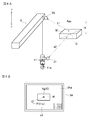
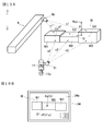
- FIG. 5A is a diagram showing a shooting situation of a luggage (with a marker) by a boom camera and a hook camera and a display situation of a shot image
- FIG. 5A is a diagram showing a shooting situation of luggage by the boom camera and the hook camera
- FIG. 5A is a diagram showing a shooting situation of luggage by the boom camera and the hook camera
- FIG. 5B is a display. It is a figure which shows the display condition of the image in an apparatus. It is a flowchart which shows the control method of the automatic operation of a crane based on the image processing result of a camera image. It is a figure which shows the reverse dynamics model of a crane. It is a flowchart which shows the control process based on the reverse dynamics model of a crane. It is a schematic diagram which shows the calculation method of the gravity center position of the load which is a complex.
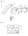
- FIG. 10A is a diagram showing a shooting situation of a luggage (without a marker) which is a composite body by the boom camera and the hook camera and a display situation of the shot video, and FIG.
- FIG. 10A is a diagram showing a shooting situation of the luggage by the boom camera and the hook camera.
- FIG. 6 is a diagram showing a display state of an image on a display device.
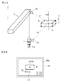
- FIG. 11A is a diagram showing a shooting situation of a luggage (with a marker) as a complex by the boom camera and the hook camera and a display situation of a shot image
- FIG. 11A is a diagram showing a shooting situation of the luggage by the boom camera and the hook camera
- FIG. 6 is a diagram showing a display state of an image on a display device.
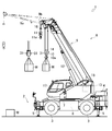
- a crane 1 which is a crane (rough terrain crane) according to an embodiment of the present invention will be described below with reference to FIGS. 1 and 2.
- a rough terrain crane will be described as an example, but a crane according to an embodiment of the present invention is a crane of other forms such as an all-terrain crane, a truck crane, and a loading truck crane. Good.
- the crane 1 is a mobile crane that can move to an unspecified place.
- the crane 1 has a vehicle 2 and a crane device 6.
- the vehicle 2 is a traveling body that carries the crane device 6.
- the vehicle 2 has a plurality of wheels 3 and runs with the engine 4 as a power source.
- the vehicle 2 is provided with an outrigger 5.
- the outrigger 5 is composed of a projecting beam that can be hydraulically extended on both sides in the width direction of the vehicle 2 and a hydraulic jack cylinder that can be extended in a direction perpendicular to the ground.
- the crane device 6 is, for example, a work device capable of hooking and lifting a load W placed on the ground with a hook suspended on a wire rope.
- the crane device 6 includes a swivel base 7, a boom 9, a main hook block 10, a sub hook block 11, an undulating hydraulic cylinder 12, a main winch 13, a main wire rope 14, a sub winch 15, a sub wire rope 16 and a cabin 17. I have it.
- the swivel base 7 is a rotating device configured to swivel the crane device 6 on the vehicle 2.
- the swivel base 7 is provided on the frame of the vehicle 2 via an annular bearing.
- the swivel base 7 is configured to be rotatable about a center of an annular bearing as a center of rotation.
- the revolving base 7 is provided with a hydraulic revolving hydraulic motor 8 as an actuator.
- the revolving base 7 is configured to be revolvable in one direction and the other direction around the bearing by a revolving hydraulic motor 8.
- the swing hydraulic motor 8 that is an actuator is rotated by a swing valve 23 that is an electromagnetic proportional switching valve.
- the turning valve 23 can control the flow rate of the hydraulic oil supplied to the turning hydraulic motor 8 to an arbitrary flow rate. That is, the revolving base 7 is configured to be controllable to an arbitrary revolving speed via the revolving hydraulic motor 8 rotatably operated by the revolving valve 23.
- the turning base 7 is provided with a turning sensor 27.
- the boom 9 is a movable column that supports the wire rope so that the luggage W can be lifted.
- the boom 9 is composed of a plurality of boom members.
- the boom 9 is provided such that the base end of the base boom member is swingable substantially at the center of the swivel base 7.
- the boom 9 is configured to be extendable/contractible in the axial direction by moving each boom member by an extension/contraction hydraulic cylinder (not shown) which is an actuator. Further, the boom 9 is provided with a jib 9a.
- a telescopic hydraulic cylinder (not shown) which is an actuator is telescopically operated by a telescopic valve 24 which is an electromagnetic proportional switching valve.
- the expansion/contraction valve 24 can control the flow rate of the hydraulic oil supplied to the expansion/contraction hydraulic cylinder to an arbitrary flow rate.
- the boom 9 is provided with a telescopic sensor 28 that detects the length of the boom 9.
- the boom camera 9b which is a detection device, captures the luggage W and features around the luggage W.
- the boom camera 9b is provided at the tip of the boom 9.
- the boom camera 9b is capable of capturing an image of the ground from above, and is configured to be able to acquire an image s1 that is an image of the situation on the ground (features and terrain around the crane 1) and the luggage W placed on the ground.
- the main hook block 10 and the sub hook block 11 are for hanging the luggage W.
- the main hook block 10 is provided with a plurality of hook sheaves around which the main wire rope 14 is wound, and a main hook 10a for hanging the luggage W.
- the sub-hook block 11 is provided with a sub-hook 11a for hanging the luggage W.
- the undulating hydraulic cylinder 12 is an actuator that raises and lowers the boom 9 and holds the posture of the boom 9.
- the undulating hydraulic cylinder 12 has an end of a cylinder portion swingably connected to the swivel base 7, and an end of a rod portion swingably connected to a base boom member of the boom 9.
- the undulating hydraulic cylinder 12 is expanded and contracted by an undulating valve 25 which is an electromagnetic proportional switching valve.
- the undulation valve 25 can control the flow rate of the hydraulic oil supplied to the undulation hydraulic cylinder 12 to an arbitrary flow rate.
- the boom 9 is provided with an undulation sensor 29.
- the main winch 13 and the sub winch 15 carry out (winding) and unwinding (winding) the main wire rope 14 and the sub wire rope 16.
- the main winch 13 is rotated by a main hydraulic motor (not shown) in which the main drum around which the main wire rope 14 is wound is an actuator, and the sub winch 15 is a sub drum in which the sub wire rope 16 is wound around is an actuator (not shown). It is configured to be rotated by a hydraulic motor for use.
- the main hydraulic motor is rotated by the main valve 26m, which is an electromagnetic proportional switching valve.
- the main winch 13 is configured such that the main hydraulic motor is controlled by the main valve 26m and the main winch 13 can be operated at an arbitrary feeding and drawing speed.
- the sub winch 15 is configured such that the sub hydraulic valve 26s, which is an electromagnetic proportional switching valve, controls the sub hydraulic motor, and can be operated at arbitrary feeding and feeding speeds.
- Each of the main winch 13 and the sub winch 15 is provided with a winding sensor 30 that detects a payout amount 1 of the main wire rope 14 and the sub wire rope 16, respectively.
- Cabin 17 is a casing that covers the cockpit.
- the cabin 17 is mounted on the swivel base 7 and is provided with a cockpit (not shown).
- the turning operation tool 18 can operate the turning hydraulic motor 8.
- the hoisting operation tool 19 can operate the hoisting hydraulic cylinder 12.
- the extension/contraction operation tool 20 can operate an extension/contraction hydraulic cylinder.
- the main drum operation tool 21m can operate the main hydraulic motor.
- the sub-drum operation tool 21s can operate the sub hydraulic motor.
- the GNSS receiver 22 is a receiver that constitutes a global navigation satellite system (Global Navigation Satellite System), and receives ranging radio waves from satellites and calculates the latitude, longitude, and altitude that are the position coordinates of the receiver. Is.
- the GNSS receiver 22 is provided at the tip of the boom 9 and the cabin 17 (hereinafter, the GNSS receiver 22 provided at the tip of the boom 9 and the cabin 17 is generically referred to as "GNSS receiver 22". )). That is, the crane 1 can acquire the position coordinates of the tip of the boom 9 and the position coordinates of the cabin 17 by the GNSS receiver 22 on the crane 1 side.
- the hook camera 31 is a device that captures an image of the luggage W.
- the hook camera 31 is detachably provided on the hook block to be used among the main hook block 10 and the sub hook block 11 by a magnet or the like.
- FIG. 1 illustrates a case where a pair of hook cameras 31 and 31 are provided in the main hook block 10. 4A and 4B, 5A and 5B, 7, and 8, the case where the hook camera 31 is provided in the sub hook block 11 is illustrated.
- the hook camera 31 is configured so that the shooting direction can be changed by a control signal from the crane device 6.
- two or more hook cameras 31 are provided in consideration of the fact that the luggage W may not be captured depending on the orientation of the main hook block 10 and the positional relationship of the luggage W.
- One hook camera 31 may be provided at a position where the field of view is not obstructed by the main hook block 10.
- the camera (hook camera 31) provided on the main hook block 10 is exemplified as the camera other than the boom camera 9b, but it may be any configuration as long as the image of the luggage W can be acquired from different viewpoints.
- a camera may be provided at a position where the luggage W in front of the cabin 17 can be visually recognized.
- one of the plurality of hook cameras 31, 31 is arranged on one side surface of the main hook block 10 and is configured as a first hook camera 31 capable of photographing the luggage W on the ground surface.
- the other hook camera 31 of the plurality of hook cameras is arranged on the other side surface of the main hook block 10 and is configured as a second hook camera 31 capable of photographing the luggage W on the ground surface.
- the hook cameras 31 and 31 can transmit the captured image s2 by wireless communication or the like.
- the crane 1 is equipped with a boom camera 9b and a hook camera 31 as cameras for photographing the luggage W, and is configured to be able to acquire images s1 and s2 obtained by simultaneously photographing the luggage W from different directions.
- the communication device 33 receives the data of the image s2 from the hook camera 31. Further, the communication device 33 can acquire the information of the luggage W and the three-dimensional data of the structure from a BIM (Building Information Modeling) 40 which is a storage device operated by an external server or the like. The communication device 33 is configured to transfer the image s2 to the control device 35 via a communication line (not shown). The communication device 33 is provided in the cabin 17.
- BIM Building Information Modeling
- the BIM 40 is a database in which attribute data such as three-dimensional shape, material and weight of each material constituting a building is added to a three-dimensional digital model created by a computer, and the design, construction and maintenance of the building.
- the database information can be utilized in all steps up to.
- the luggage W is included in the above-mentioned "each material constituting the building".
- the BIM 40 is composed of an external server or the like that can be accessed in real time, and the database information is registered. Note that, in the present embodiment, the case where the BIM 40 configured by an external server is used as the storage device in which the information of the luggage W is stored is exemplified, but the information of the luggage W and the like is previously stored in the crane 1.
- the storage device may be installed so that the information of the luggage W and the three-dimensional data of the structure can be acquired without performing communication with the outside.
- the display device 34 displays the image s1 captured by the boom camera 9b and the image s2 captured by the hook camera 31, and can superimpose and display information calculated by performing image processing on these images s1 and s2. Output device.
- the display device 34 has a function as an input device for the operator to instruct a luggage for which the suspension position is desired to be acquired (that is, an image processing target).
- the display device 34 is equipped with a touch panel capable of instructing the parcel to be subjected to image processing by tapping the parcel image displayed on the screen, and an operation tool such as a mouse (not shown).
- the display device 34 is provided in the cabin 17.
- the control device 35 controls each actuator of the crane 1 via each operation valve. Further, the control device 35 performs image processing of the images s1 and s2 captured by the boom camera 9b or the hook camera 31.
- the control device 35 is provided in the cabin 17.
- the control device 35 may have a configuration in which a CPU, a ROM, a RAM, a HDD, and the like are connected by a bus, or may be a configuration including a one-chip LSI or the like.
- the control device 35 stores various programs and data for controlling the operation of each actuator, switching valve, sensor and the like and processing image data.
- the control device 35 is connected to the turning sensor 27, the extension/contraction sensor 28, the undulation sensor 29, the undulation sensor 29, and the winding sensor 30, and the turning angle ⁇ z, the extension/contraction length Lb, and the undulation angle ⁇ x of the swivel base 7. Also, the amount of wire rope feeding l can be obtained.
- control device 35 is connected to the boom camera 9b, can acquire the image s1 captured by the boom camera 9b, and can display the image s1 on the display device 34.
- the control device 35 is also connected to the communication device 33 and the display device 34, can acquire the image s2 captured by the hook camera 31, and can display the image s2 on the display device 34.
- control device 35 is connected to the turning operation tool 18, the up-and-down operation tool 19, the telescopic operation tool 20, the main drum operation tool 21m, and the sub-drum operation tool 21s. Then, when the crane 1 is operated by the manual operation of the operator, the control device 35 acquires the respective operation amounts of the turning operation tool 18, the hoisting operation tool 19, the main drum operation tool 21m, and the sub-drum operation tool 21s, and various The target speed signal Vd of the sub-hook 11a generated by operating the operation tool is generated.
- the control device 35 controls the actuator posture corresponding to each operation tool based on the operation amounts of the turning operation tool 18, the up-and-down operation tool 19, the main drum operation tool 21m, and the sub-drum operation tool 21s (that is, the target speed signal Vd).
- the signal Ad is generated.
- the control device 35 generates the actuator attitude signal Ad based on the image processing result of the image s1 captured by the boom camera 9b and the image s2 captured by the hook camera 31.
- the control device 35 is connected to the turning valve 23, the expansion/contraction valve 24, the undulation valve 25, the main valve 26m and the sub valve 26s, and the turning valve 23, the undulation valve 25, the main valve 26m and the sub valve.
- the actuator attitude signal Ad can be transmitted to the valve 26s.
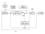
- the control device 35 has a target position calculation unit 35a, a hook position calculation unit 35b, and an attitude signal generation unit 35c.
- the target position calculation unit 35a which is a part of the control device 35, performs image processing on the images s1 and s2 to calculate the target position Pd that is the movement target of the sub-hook 11a. Further, the hook position calculation unit 35b is a part of the control device 35, and calculates the hook position P, which is the current position information of the sub hook 11a, from the image processing result of the image captured by the boom camera 9b.
- the attitude signal generation unit 35c also calculates an actuator attitude signal Ad that is a command signal to the crane 1.
- the crane 1 configured as described above can move the crane device 6 to an arbitrary position by running the vehicle 2. Further, the crane 1 raises the boom 9 at an arbitrary hoisting angle ⁇ x by the hoisting hydraulic cylinder 12 by operating the hoisting operation tool 19, and extends the boom 9 to an arbitrary boom 9 length by operating the telescopic operation tool 20. By doing so, the lift and working radius of the crane device 6 can be expanded. In addition, the crane 1 can move the sub-hook 11a to an arbitrary position by moving the sub-hook 11a up and down by the sub-drum operation tool 21s and the like and turning the swivel base 7 by operating the turning operation tool 18.
- the crane 1 can automatically move the sub-hook 11a to a predetermined position by the control device 35 without depending on the operation of each operation tool.
- the predetermined position mentioned here is a position of the sub-hook 11a suitable for hanging the luggage W, for example, a position of a suspender attached to the luggage W or a position above the center of gravity of the luggage W.
- a hanging position Ag such a predetermined position will be referred to as a hanging position Ag.
- the crane 1 can move the sub-hook 11a to the hanging position Ag of the load W by the automatic operation before the load W is transported.
- the control device 35 causes the image processing unit 35d to acquire and perform image processing on the images s1 and s2 captured by the boom camera 9b and the hook camera 31, so that the image processing unit 35d causes the load W to be stored.
- Three-dimensional shape information Ja which is information related to the three-dimensional shape, is generated.
- the control device 35 generates an actuator posture signal Ad corresponding to the state of the load W (the position of the center of gravity, the installation position, the posture, etc.) based on the generated three-dimensional shape information Ja.
- the boom 9 is automatically erected at an arbitrary undulation angle ⁇ x by the undulation hydraulic cylinder 12 based on the image processing result of the images s1 and s2 regarding the load W by the control device 35.
- the boom 9 can be automatically extended to an arbitrary length of the boom 9.
- the crane 1 automatically moves the sub-hook 11a to an arbitrary upper or lower position based on the image processing result of the image of the luggage W by the control device 35, or automatically rotates the swivel base 7 to an arbitrary swivel angle.
- the sub-hook 11a can be automatically moved to an arbitrary position by turning the sub-hook 11a.
- the crane 1 is used for the purpose of automatically installing the luggage W at a predetermined position by moving the sub-hook 11a to a position directly above the luggage W when the luggage W is installed at the predetermined position. Can also be used.
- the crane 1 may automatically convey the luggage W to the installation position of the luggage W. It will be possible.
- the control device 35 acquires an image s1 obtained by shooting the luggage W with the boom camera 9b and an image s2 obtained by simultaneously taking the same luggage W with the hook camera 31 with the image processing unit 35d.
- the image processing unit 35d performs image processing from each of the images s1 and s2 based on the principle of the stereo camera, and information on the distance between the sub-hook 11a and the luggage W and information on the three-dimensional shape of the luggage W (hereinafter, three-dimensional information).
- the shape information Ja) is calculated.
- the three-dimensional shape information Ja is information relating to the outer shape of the luggage W and includes dimension information.
- the control device 35 collates the calculated three-dimensional shape information Ja with the information on the three-dimensional shape of the package W registered in the BIM 40 (hereinafter, referred to as master information Jm) by the center-of-gravity setting unit 35e, and 3 Master information Jm whose outer shape and dimensions match the dimensional shape information Ja is searched. Then, when the center-of-gravity setting unit 35e detects the master information Jm that matches the three-dimensional shape information Ja, the master information Jm is associated with the information W of the package W related to the images s1 and s2.
- the master information Jm is information registered in the BIM 40, and information about the three-dimensional shape, weight, center of gravity position, etc. of the luggage W is prepared for each type of luggage W.
- the master information Jm is prepared by previously inputting into the BIM 40 for each package W scheduled to be transported by the crane 1.
- the crane 1 includes a display device 34.
- the display device 34 includes a display 34a (see FIG. 4B) capable of displaying the image s1 captured by the boom camera 9b, and displays the images s1 and s2 obtained by capturing the luggage W from above in real time by the cameras 9b and 31. can do. Further, the display device 34 can convert the information related to the center of gravity position G of the luggage W set by the center of gravity setting unit 35e into an image by the image conversion unit 35f, and display the image by superimposing it on the images s1 and s2. With such a configuration, the operator can confirm the gravity center position G of the luggage W on the display 34a of the display device 34.
- the display device 34 displays the images s1 and s2 of the load W and the position G of the center of gravity.
- the control device 35 sets the hanging position Ag of the luggage W based on the calculated center-of-gravity position G of the luggage W.
- the control device 35 superimposes the set suspension position Ag and the hook position P of the sub-hook 11a on the images s1 and s2 including the marker M and displays them on the display 34a of the display device 34. The operator can accurately grasp the positional relationship between the hook position P of the sub-hook 11a and the hanging position Ag by the display device 34.
- the operator operates the sub-hook 11a so that the position of the sub-hook 11a coincides with the suspension position Ag (center of gravity G) while observing the image displayed on the display 34a, and arranges the sub-hook 11a at the suspension position Ag. It is also possible.
- the display device 34 is configured such that the distance of the sub-hook 11a to the suspension position Ag is displayed on the display 34a as a numerical value as a distance in each of the XYZ axial directions. By looking at this numerical value, for example, the distance between the sub-hook 11a and the hanging position Ag in the height direction can be grasped.
- the display device 34 may display the image s2 captured by the hook camera 31 in place of the image s1 captured by the boom camera 9b when the hook camera 31 approaches the luggage W within a predetermined distance. It is configured to be able to.
- the hook camera 31 can photograph the luggage W at a position closer to the luggage W than the boom camera 9b, and can obtain a more detailed (high-definition) image of the luggage W. Therefore, by switching the camera images to be displayed according to the distance between the cameras 9b and 31 and the baggage W, the closer the hook camera 31 is to the baggage W, the more the calculation accuracy of the center of gravity position G by image processing improves, As a result, the positioning accuracy of the sub hook 11a can be improved.
- the control device 35 identifies information relating to the posture of the luggage W (hereinafter referred to as posture information Jb) from the calculated three-dimensional shape information Ja.
- the posture information Jb is information relating to the posture of the baggage W (what direction it is arranged). Further, the control device 35 acquires the center of gravity position G of the luggage W from the linked master information Jm, and specifies the three-dimensional coordinates of the center of gravity position G of the luggage W based on the posture information Jb and the center of gravity position G. To do.
- the crane 1 has a plurality of markers M provided on the surface of the load W, and the markers M are read by the boom camera 9b and the hook camera 31, so that the three-dimensional shape information Ja of the load W and The attitude information Jb may be acquired.
- markers M of different types are arranged on each side surface (eg, each corner portion) of the luggage W, and three or more markers M are attached to the boom camera 9b and the hook camera 31.
- the posture information Jb is acquired from the relative positional relationship of the three or more markers M.
- the crane 1 can acquire the three-dimensional shape information Ja by specifying the master information Jm of the luggage W from the marker M, and further can acquire the posture information Jb from the positional relationship of each marker M. Information regarding what kind of marker M is provided in what kind of arrangement on the luggage W is registered in advance in the BIM 40 or the control device 35.
- the control device 35 sets the suspending position Ag immediately above based on the specified center-of-gravity position G.
- the hanging position Ag is a position on a vertical line passing through the center of gravity position G of the load W, and is a position separated from the center of gravity position G vertically by a predetermined distance H as shown in FIG. 4A.
- the distance H is set in consideration of the size of the luggage W, the length of the suspension wire used for slinging, and the like.
- the hanging position Ag is set as three-dimensional coordinates.
- the suspending position is specified by setting the suspending position Ag, or information on the suspending device relating to the luggage W is registered in advance in the BIM 40, and the suspending device information (suspension position) registered in the BIM 40 is used.
- the hanging position Ag can be set.
- the control device 35 superimposes the set suspension position Ag and the hook position P of the sub-hook 11a on the images s1 and s2 including the marker M and displays them on the display 34a of the display device 34.
- the operator can accurately grasp the positional relationship between the hook position P of the sub-hook 11a and the hanging position Ag by the display device 34.
- the operator of the crane 1 looks at the display 34a of the display device 34 while watching the load W to be conveyed by the boom camera 9b.
- the crane 1 is operated so that it can be photographed.
- the operator designates the luggage W to be transported among the luggage W displayed on the display 34a (for example, taps the screen).
- the crane 1 starts the following automatic operation when the operator performs an operation of designating the luggage W to be transported.
- the target position calculation unit 35a of the control device 35 acquires the images s1 and s2 from each of the cameras 9b and 31 at every unit time t and outputs the images s1 and s2.
- the type of the luggage W is specified from the three-dimensional shape information Ja and the posture information Jb obtained by image processing, and the target position Pd is calculated.
- the target position calculation unit 35a calculates the target position Pd based on the master information Jm of the package W registered in the BIM 40.
- the target position Pd includes information on the center of gravity G of the luggage W and the hanging position Ag.
- the hook position calculation unit 35b calculates the hook position P, which is the current position information of the sub-hook 11a, from the image processing result of the image s1 taken by the boom camera 9b.
- the attitude signal generator 35c calculates a relative distance Dp between the current hook position P and the set target position Pd.
- the posture signal generation unit 35c calculates the relative distance Dp from the image processing result of the images captured by the boom camera 9b and the hook camera 31.
- the posture signal generation unit 35c performs the inverse model calculation based on the calculated relative distance Dp, and the boom posture angle (turning angle ⁇ z, extension/contraction length lb, undulation) for matching the hook position P with the target position Pd.
- An angle ⁇ x) and a feedforward amount (also referred to as an FF amount) of the wire rope payout amount 1 are calculated.
- the inverse model calculation is to calculate the exercise command necessary to realize the desired exercise result from the desired exercise result.
- the attitude signal generator 35c feeds back the current hook position P from the crane information detected by each sensor, performs inverse model calculation based on the difference from the target position Pd, and sets the hook position P to the target position.
- a feedback amount also referred to as an FB amount
- a boom attitude angle turning angle ⁇ z, extension/contraction length lb, undulation angle ⁇ x
- a wire rope payout amount 1 for matching with Pd is calculated.
- the attitude signal generation unit 35c adds up the FF amount and the FB amount to calculate the actuator attitude signal Ad which is a command signal to the crane 1.
- the control device 35 In the crane 1 including the control device 35 configured in this way, the control device 35 outputs the calculated actuator attitude signal Ad to each valve to bring the hook position P closer to the target position Pd. Then, the control device 35 repeatedly executes the calculation of the actuator attitude signal Ad in a predetermined cycle until the hook position P and the target position Pd match. The control device 35 determines that the hook position P and the target position Pd match when the distance between the hook position P and the target position Pd becomes equal to or less than a predetermined threshold value. The final hook position P is determined as a result of the influence of the disturbance D on the operation of the crane 1 based on the actuator attitude signal Ad.
- the target position Pd is calculated based on the images captured by the boom camera 9b and the hook camera 31, and the position control is performed based on the distance information. It is possible to reduce the alignment error as compared with the control alignment.
- an inverse dynamic model of the crane 1 is determined as shown in FIG.
- the inverse dynamic model is defined in the XYZ coordinate system which is a global coordinate system, and the origin O is the turning center of the crane 1.
- the global coordinates of the origin O are acquired from the GNSS receiver 22.
- q indicates, for example, the current position coordinate q(n) of the tip of the boom 9
- p indicates, for example, the current position coordinate p(n) of the sub-hook 11a.
- lb indicates the extension/contraction length lb(n) of the boom 9
- ⁇ x indicates the undulation angle ⁇ x(n)
- ⁇ z indicates the turning angle ⁇ z(n), for example.
- l indicates the wire rope payout amount l(n)
- f indicates the wire rope tension f
- e indicates the wire rope direction vector e(n), for example.
- the relationship between the target position q of the tip of the boom 9 and the target position p of the subhook 11a is based on the target position p of the subhook 11a, the mass m of the subhook 11a, and the spring constant kf of the wire rope.
- the target position q of the tip of the boom 9 is represented by the equation (1), and is calculated by the equation (2) which is a function of the time of the sub-hook 11a.
- the low pass filter Lp attenuates frequencies above a predetermined frequency.
- the target position calculation unit 35a applies the low-pass filter Lp to the signal of the target position Pd to prevent the occurrence of a singular point (rapid position change) due to the differential operation.
- the low-pass filter Lp uses the fourth-order low-pass filter Lp in order to correspond to the fourth-order differential when calculating the spring constant kf, but the low-pass filter Lp of the order matched to the desired characteristic is applied. be able to.
- a and b are coefficients.
- the pay-out amount l(n) of the wire rope is calculated from the following equation (4).
- the wire rope payout amount l(n) is defined by the distance between the current position coordinate q(n) of the boom 9 which is the tip position of the boom 9 and the current position coordinate p(n) of the subhook 11a which is the position of the subhook 11a. It In other words, the wire rope payout amount l(n) includes the length of the sling.
- the direction vector e(n) of the wire rope is calculated from the following equation (5).
- the wire rope direction vector e(n) is a unit length vector of the wire rope tension f (see Formula (1)).
- the tension f of the wire rope is obtained by subtracting the gravitational acceleration from the acceleration of the subhook 11a calculated from the current position coordinate p(n) of the subhook 11a and the target position coordinate p(n+1) of the subhook 11a after the unit time t has elapsed. is there.
- the target position coordinate q(n+1) of the boom 9 that is the target position of the tip of the boom 9 after the unit time t has elapsed is calculated from the following expression (1) as a function of n (6).
- ⁇ indicates the turning angle ⁇ z(n) of the boom 9.
- the target position coordinate q(n+1) of the boom 9 is calculated from the feed amount l(n) of the wire rope, the target position coordinate p(n+1) of the subhook 11a, and the direction vector e(n+1) using inverse dynamics. ..
- the target position calculation unit 35a can acquire the images s1 and s2 from the cameras 9b and 31 at each unit time t, and from the three-dimensional shape information Ja and the posture information Jb obtained by performing the image processing on the images s1 and s2.
- the target position Pd is calculated while specifying the type of the luggage W.
- the hook position calculation unit 35b calculates the hook position P, which is the current position information of the sub hook 11a, from the image processing result of the image s1 captured by the boom camera 9b. In addition, the hook position calculation unit 35b calculates the position coordinates of the tip of the boom 9 from the attitude information of the boom 9, and the main wire rope 14 or the sub wire rope 16 (hereinafter simply referred to as "wire rope") from the winding sensor 30.
- the feeding amount l(n) of the hook position P may be calculated as the position coordinate of the sub-hook 11a.
- the hook position calculation unit 35b acquires the turning angle ⁇ z(n) of the turntable 7 from the turning sensor 27, the expansion/contraction length lb(n) from the expansion/contraction sensor 28, and the undulation sensor 29. Acquire the undulation angle ⁇ x(n).
- the hook position calculation unit 35b calculates the current position coordinates p(n) of the sub-hook 11a that is the acquired current hook position P, and acquires the acquired turning angle ⁇ z(n), the expansion/contraction length lb(n), and the undulation. From the angle ⁇ x(n), the current position coordinate q(n) of the tip of the boom 9 (the wire rope feeding position), which is the current position of the tip of the boom 9, is hereinafter referred to simply as “current position coordinate q(n) of the boom 9”. Note) can be calculated.
- the hook position calculation unit 35b can also calculate the wire rope payout amount l(n) from the current position coordinate p(n) of the sub-hook 11a and the current position coordinate q(n) of the boom 9. Further, the hook position calculation unit 35b suspends the sub-hook 11a from the current position coordinate p(n) of the sub-hook 11a and the target position coordinate p(n+1) of the sub-hook 11a which is the target position of the sub-hook 11a after the unit time t has elapsed. It is possible to calculate the direction vector e(n+1) of the wire rope that is being provided.
- the hook position calculation unit 35b is a target position of the tip of the boom 9 after a unit time t has elapsed from the target position coordinate p(n+1) of the sub-hook 11a and the wire rope direction vector e(n+1) by using inverse dynamics. It is configured to calculate the target position coordinate q(n+1) of the boom 9.
- the attitude signal generator 35c generates an actuator attitude signal Ad from the target position coordinates q(n+1) of the boom 9 after the unit time t has elapsed.
- the attitude signal generator 35c can acquire the target position coordinate q(n+1) of the boom 9 after the unit time t has elapsed from the hook position calculator 35b.
- the attitude signal generator 35c is configured to generate an actuator attitude signal Ad to the turning valve 23, the expansion/contraction valve 24, the undulation valve 25, the main valve 26m or the sub valve 26s.
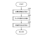
- step S100 the control device 35 starts the target position calculation step A.
- the control device 35 calculates the suspension position Ag from the acquired center-of-gravity position G of the luggage W every unit time t, and when the target position calculation step A ends, moves the step to step S200.
- the control device 35 starts the hook position calculation step B.
- the control device 35 calculates the target position coordinate q(n+1) of the boom 9 from the current position coordinate p(n) of the sub-hook 11a and the current position coordinate q(n) of the boom 9, and when the hook position calculation step B ends, the step is completed. To step S300.
- step 300 the control device 35 starts the operation signal generation process C.
- the control device 35 controls the turning valve 23 and the expansion/contraction valve 24 based on the rotation angle ⁇ z(n+1) of the revolving base 7, the expansion/contraction length Lb(n+1), the undulation angle ⁇ x(n+1), and the wire rope payout amount l(n+1).
- the actuator attitude signal Ad of the undulation valve 25, the main valve 26m, or the sub valve 26s is generated, and the operation signal generation step C is ended and the step proceeds to step S100.
- the control device 35 calculates the target position coordinates q(n+1) of the boom 9 by repeating the target position calculation process A, the hook position calculation process B, and the operation signal generation process C, and after the unit time t has elapsed, the wire rope is calculated.
- the wire rope direction vector e(n+2) is calculated from the feed amount l(n+1) of the wire hook, the current position coordinate p(n+1) of the subhook 11a, and the target position coordinate p(n+2) of the subhook 11a, and the wire rope feed amount l(n From n+1) and the wire rope direction vector e(n+2), the target position coordinate q(n+2) of the boom 9 after the unit time t has further elapsed is calculated.
- control device 35 calculates the direction vector e(n) of the wire rope and uses the inverse dynamics to calculate the current position coordinate p(n+1) of the subhook 11a, the target position coordinate p(n+1) of the subhook 11a, and the wire rope.
- the target position coordinate q(n+1) of the boom 9 after the unit time t is sequentially calculated from the directional vector e(n) of.
- the controller 35 controls each actuator by feedforward control that generates an actuator attitude signal Ad based on the target position coordinate q(n+1) of the boom 9.
- the crane 1 calculates the target position Pd based on the images captured by the boom camera 9b and the hook camera 31, so that the position control is performed based on the distance information. As a result, the positioning error can be reduced compared to the conventional positioning by speed control.
- the crane 1 also generates a control signal for the boom 9 based on the distance between the target position Pd and the hook position P, and a feedforward control for generating the control signal for the boom 9 based on the target trajectory intended by the operator. Has been applied. Therefore, the crane 1 has a small response delay with respect to the operation signal, and suppresses the swing of the luggage W due to the response delay.
- an inverse dynamic model is constructed, and the target position coordinate q of the boom 9 is calculated from the wire rope direction vector e(n), the current position coordinate p(n+1) of the subhook 11a, and the target position coordinate p(n+1) of the subhook 11a. Since (n+1) is calculated, an error in a transient state due to acceleration/deceleration or the like does not occur. Further, since the frequency component including the singular point caused by the differential operation when calculating the target position coordinate q(n+1) of the boom 9 is attenuated, the control of the boom 9 is stabilized. Accordingly, when the sub-hook 11a is moved to the hanging position Ag which is the target position, it is possible to suppress the sub-hook 11a from swinging.
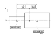
- the weight A and the position of the center of gravity Ga of the luggage Wa are known from the information registered in the BIM 40.
- the weight B and the center of gravity position Gb of the luggage Wb are known from the information registered in the BIM 40.
- the weight of the luggage W is (A+B).
- the center of gravity position G of the luggage W is located on the straight line Xg connecting the center of gravity position Ga and the center of gravity position Gb. Then, the position on the straight line Xg where the center of gravity G of the luggage W is located is determined by the weight ratio between the luggage Wa and the luggage Wa.
- the control device 35 controls the information of each of the loads Wa and Wb from the BIM 40 (weight, center of gravity position, posture, shape after connection).
- the center of gravity position G of the load W which is a combined body, can be calculated by obtaining and performing the above calculation.
- the center of gravity position G of the luggage W can be calculated by applying the above calculation.
- the information (weight, center of gravity position, posture, shape) of the baggage W which is a complex is displayed in the BIM 40. May be registered in advance and the information of the package W as the complex may be directly used.
- the control device 35 uses the hook camera 31 to capture images s1, s1, and s1 of three packages W1, W2, and W3 captured by the boom camera 9b and, at the same time, the same package W using the hook camera 31.
- the captured images s2, s2, and s2 are acquired by the image processing unit 35d.
- the image processing unit 35d performs image processing on the images s1 and s2 based on the principle of a stereo camera, and calculates the three-dimensional shape information Ja of the luggage W.
- the control device 35 detects that the package W is composed of three packages W1, W2, W3 based on the three-dimensional shape information Ja. Then, the control device 35 calculates individual three-dimensional shape information Ja1, Ja2, Ja3 for each of the three packages W1, W2, W3.
- the control device 35 collates the calculated three-dimensional shape information Ja1, Ja2, Ja3 with the master information Jm registered in the BIM 40 by the center-of-gravity setting unit 35e to obtain the three-dimensional shape information Ja1, Ja2, Ja3. Master information Jm1, Jm2, and Jm3 having the same outer shape and size are searched. Then, when the center-of-gravity setting unit 35e detects the respective master information Jm1, Jm2, Jm3 that matches the respective three-dimensional shape information Ja1, Ja2, Ja3, the master information Jm1, Jm2, Jm3 is set as the image s1, s2. It is linked to each of the packages W1, W2, and W3 related to the information.
- the control device 35 identifies the posture information Jb1, Jb2, Jb3 relating to the postures of the respective packages W1, W2, W3 forming the package W from the calculated respective three-dimensional shape information Ja1, Ja2, Ja3. Further, the control device 35 acquires the center of gravity positions G1, G2, G3 of the respective packages W from the linked master information Jm, and based on the respective posture information Jb1, Jb2, Jb3 and the center of gravity positions G1, G2, G3. Then, the three-dimensional coordinates of the center of gravity position G of the luggage W are specified.
- the control device 35 sets the suspension position Ag of the luggage W based on the calculated center-of-gravity position G of the luggage W. As shown in FIG. 10B, the control device 35 displays the hanging position Ag set on the luggage W and the hook position P of the sub-hook 11a on the images 34 and 2 on the display 34a of the display device 34 by superimposing them on the images s1 and s2. The operator can accurately grasp the positional relationship between the hook position P of the sub-hook 11a and the hanging position Ag by the display device 34.
- the control device 35 individually captures the loads W1, W2, and W3 and calculates the center of gravity position G of the load W that is a complex.
- the three-dimensional shape information Ja is registered in the BIM 40
- the luggage W is grasped as one body
- the posture information Jb of the luggage W as a complex is calculated using the three-dimensional shape information Ja of the BIM 40
- the control device 35 is used.
- the center of gravity position G of the package W as a complex may be directly calculated from the three-dimensional shape information Ja and the posture information Jb.
- the crane 1 uses the markers M provided on the loads W1, W2, W3 to determine the three-dimensional shape information Ja of the load W.
- the posture information Jb may be acquired, the center of gravity position G of the luggage W may be calculated, and the suspension position Ag may be set.
- the crane 1 acquires the three-dimensional shape information Ja and the posture information Jb of the luggage W by reading the plurality of markers M provided on the surface of the luggage W with the boom camera 9b and the hook camera 31. be able to.
- the control device 35 may separately capture the loads W1, W2, and W3 and calculate the respective gravity center positions G1, G2, and G3, and then calculate the gravity center position G of the load W, or a composite body.
- the luggage W is regarded as one body, and the control device 35 controls the three-dimensional shape information Ja and the posture information Jb based on the information obtained by reading the marker M. May be obtained, and the gravity center position G of the package W as a complex may be directly calculated.
- the control device 35 sets the suspension position Ag of the luggage W based on the calculated center-of-gravity position G of the luggage W. As shown in FIG. 11B, the control device 35 superimposes the set suspension position Ag and the hook position P of the sub-hook 11a on the images s1 and s2 including the marker M and displays them on the display 34a of the display device 34. The operator can accurately grasp the positional relationship between the hook position P of the sub-hook 11a and the hanging position Ag by the display device 34.
- the crane 1 which is a mobile crane has been described as an example in the present embodiment
- the method of automatically operating the hook according to the present invention is applied to various devices configured to lift the load W by the hook.
- the crane 1 may be configured such that the moving direction of the load W is instructed in the tilt direction and the crane 1 is remotely controlled by a remote operation terminal having an operation stick for instructing the moving speed of the load W in the tilt angle.
- the crane 1 displays the image captured by the hook camera on the remote control terminal, so that the operator can accurately grasp the situation around the luggage W even from a remote location.
- the crane 1 can improve the robustness by feeding back the current position information of the luggage W based on the image captured by the hook camera. In this way, the crane 1 can move the cargo W stably without being aware of the weight of the cargo W or the change in characteristics due to disturbance.
- the present invention can be applied to a crane.
Landscapes
- Engineering & Computer Science (AREA)
- Mechanical Engineering (AREA)
- Automation & Control Theory (AREA)
- Control And Safety Of Cranes (AREA)
- Jib Cranes (AREA)
Abstract
La présente invention vise à fournir une grue apte à détecter un emplacement de suspension d'une charge utile, afin de permettre un positionnement précis d'un crochet à l'emplacement de suspension de la charge utile. Cette grue (1) comprend : une flèche à mouvement vertical libre (9) disposée sur un pivot (7) ; et un bloc de crochet secondaire (11) et un crochet secondaire (11a) disposé en suspension à partir de la flèche (9). La grue comprend également : une caméra de flèche (9b) apte à l'imagerie d'une charge utile (W) qui doit être portée par la grue (1) ; des caméras de crochet (31) aptes à l'imagerie de la charge utile (W) à partir de points de vue différents de celui de la caméra de flèche (9b) ; et un dispositif de commande (35) pour commander la grue (1). Le dispositif de commande (35) acquiert des images (s1)/(s2) obtenues par imagerie de la charge utile (W) avec la caméra de flèche (9b) et les caméras de crochet (31), exécute un traitement d'image sur les images (s1)/(s2), et calcule un emplacement de suspension (Ag) de la charge utile (W).
Priority Applications (3)
| Application Number | Priority Date | Filing Date | Title |
|---|---|---|---|
| US17/420,907 US11981547B2 (en) | 2019-01-23 | 2020-01-21 | Crane |
| CN202080010027.2A CN113329966A (zh) | 2019-01-23 | 2020-01-21 | 起重机 |
| EP20744525.5A EP3915928B1 (fr) | 2019-01-23 | 2020-01-21 | Grue |
Applications Claiming Priority (2)
| Application Number | Priority Date | Filing Date | Title |
|---|---|---|---|
| JP2019-009724 | 2019-01-23 | ||
| JP2019009724A JP7192527B2 (ja) | 2019-01-23 | 2019-01-23 | クレーン |
Publications (1)
| Publication Number | Publication Date |
|---|---|
| WO2020153325A1 true WO2020153325A1 (fr) | 2020-07-30 |
Family
ID=71736494
Family Applications (1)
| Application Number | Title | Priority Date | Filing Date |
|---|---|---|---|
| PCT/JP2020/001847 Ceased WO2020153325A1 (fr) | 2019-01-23 | 2020-01-21 | Grue |
Country Status (5)
| Country | Link |
|---|---|
| US (1) | US11981547B2 (fr) |
| EP (1) | EP3915928B1 (fr) |
| JP (1) | JP7192527B2 (fr) |
| CN (1) | CN113329966A (fr) |
| WO (1) | WO2020153325A1 (fr) |
Cited By (3)
| Publication number | Priority date | Publication date | Assignee | Title |
|---|---|---|---|---|
| CN115724360A (zh) * | 2021-08-31 | 2023-03-03 | 上海玖行能源科技有限公司 | 悬臂吊agv小车 |
| JP2024013688A (ja) * | 2022-07-21 | 2024-02-01 | 住友重機械工業株式会社 | 荷役支援装置、荷役支援システム及び荷役装置 |
| US20240208777A1 (en) * | 2022-12-26 | 2024-06-27 | Sumitomo Heavy Industries, Ltd. | Crane operation support device and crane |
Families Citing this family (11)
| Publication number | Priority date | Publication date | Assignee | Title |
|---|---|---|---|---|
| WO2020259829A1 (fr) * | 2019-06-26 | 2020-12-30 | Abb Schweiz Ag | Véhicule autoguidé et procédé de commande de véhicule autoguidé |
| CN111017726B (zh) * | 2019-11-19 | 2020-08-21 | 中联重科股份有限公司 | 起重机吊钩定位方法、装置、系统及工程机械 |
| CN112830401B (zh) * | 2020-10-28 | 2023-03-21 | 蚌埠市神舟机械有限公司 | 一种舟艇架设作业机构用吊架装置 |
| EP4033035B1 (fr) * | 2021-01-20 | 2026-02-25 | Volvo Autonomous Solutions AB | Système et procédé associé pour le fonctionnement à distance d'une machine de travail comprenant un outil |
| JP7485211B2 (ja) * | 2021-04-20 | 2024-05-16 | 株式会社タダノ | 巻層数の推定装置及びクレーン |
| JP7616370B2 (ja) * | 2022-01-31 | 2025-01-17 | Jfeスチール株式会社 | クレーン、運搬方法及び板部材の製造方法 |
| DE102022103283A1 (de) * | 2022-02-11 | 2023-08-17 | Liebherr-Werk Biberach Gmbh | Kran |
| JP2023157254A (ja) * | 2022-04-14 | 2023-10-26 | 中国電力株式会社 | 重量判定システムおよび重量判定プログラム |
| US20240308830A1 (en) * | 2023-03-13 | 2024-09-19 | Oshkosh Corporation | Systems and methods for direction of travel |
| CN116654776A (zh) * | 2023-03-14 | 2023-08-29 | 浙江省三建建设集团有限公司 | 一种基于bim系统的幕墙轨道吊装定位装置及其使用方法 |
| DE102023206951A1 (de) * | 2023-07-21 | 2025-01-23 | Zf Friedrichshafen Ag | Verfahren zum Betreiben eines Kransystems und Kamerasystem |
Citations (7)
| Publication number | Priority date | Publication date | Assignee | Title |
|---|---|---|---|---|
| JPH08333086A (ja) * | 1995-06-09 | 1996-12-17 | Komatsu Ltd | 吊り荷の撮像画像処理装置 |
| JP2000086159A (ja) * | 1998-09-09 | 2000-03-28 | Hokkaido Development Bureau Construction Machinery Engineering Center | 作業船の吊荷揺れ抑制装置 |
| JP2013018580A (ja) * | 2011-07-08 | 2013-01-31 | Tadano Ltd | 性能線表示装置 |
| JP2014105091A (ja) * | 2012-11-29 | 2014-06-09 | Tadano Ltd | クレーンの監視カメラ |
| WO2017208435A1 (fr) * | 2016-06-03 | 2017-12-07 | 株式会社マリタイムイノベーションジャパン | Dispositif de traitement de données, procédé et programme d'identification d'une position de cargaison levée de grue |
| JP2018030692A (ja) | 2016-08-25 | 2018-03-01 | 株式会社タダノ | クレーン車 |
| JP2018095370A (ja) * | 2016-12-09 | 2018-06-21 | 株式会社タダノ | クレーン |
Family Cites Families (23)
| Publication number | Priority date | Publication date | Assignee | Title |
|---|---|---|---|---|
| JP2594579B2 (ja) * | 1987-10-23 | 1997-03-26 | 靖機 鈴木 | 調節形吊具 |
| JPH08324963A (ja) * | 1995-05-29 | 1996-12-10 | Nippon Steel Corp | クレーンの自動運転方法及び装置 |
| JP3835774B2 (ja) * | 1997-02-14 | 2006-10-18 | 株式会社フジタ | Pcブロック設置装置の支援システム |
| KR100648449B1 (ko) * | 2005-11-19 | 2006-11-24 | (주)새텍 | 슬라브 운반을 위한 정확한 무게중심을 구하는 슬라브감지 방법 및 그 장치 |
| WO2010009570A1 (fr) * | 2008-07-21 | 2010-01-28 | Yu Qifeng | Procédé de positionnement de palan et système de levage à vision intelligente |
| CN201809065U (zh) * | 2009-11-03 | 2011-04-27 | 南通通镭软件有限公司 | 岸桥下集装箱装卸自动控制系统 |
| JP5642409B2 (ja) * | 2010-03-30 | 2014-12-17 | 株式会社タダノ | クレーンの制御装置及びクレーン |
| BR112012027304B1 (pt) | 2010-04-29 | 2020-12-22 | National Oilwell Varco L.P | sistema de controle de guindaste e processo de operação de um guindaste |
| US9300954B2 (en) | 2012-09-21 | 2016-03-29 | Tadano Ltd. | Surrounding information-obtaining device for working vehicle |
| JP6080450B2 (ja) * | 2012-09-21 | 2017-02-15 | 株式会社タダノ | 監視カメラ装置 |
| DE202012012116U1 (de) * | 2012-12-17 | 2014-03-19 | Liebherr-Components Biberach Gmbh | Turmdrehkran |
| CN104649151A (zh) * | 2013-11-19 | 2015-05-27 | 天津市科力起重设备有限公司 | 一种新型起重机 |
| CN104609303B (zh) | 2015-02-09 | 2016-09-14 | 江苏科沁光电科技有限公司 | 一种带视觉辅助的桥吊系统 |
| CN105152047A (zh) * | 2015-10-13 | 2015-12-16 | 江苏建筑职业技术学院 | 塔吊司机观察现场的装置与方法 |
| KR101646918B1 (ko) * | 2016-01-22 | 2016-08-23 | 호산엔지니어링(주) | 크레인의 사각지대 모니터링 시스템 |
| CN106395638A (zh) * | 2016-11-08 | 2017-02-15 | 芜湖市长江起重设备制造有限公司 | 生产用桥式起重机 |
| JP6888287B2 (ja) * | 2016-12-09 | 2021-06-16 | 株式会社タダノ | クレーン |
| JP6776861B2 (ja) * | 2016-12-09 | 2020-10-28 | 株式会社タダノ | 移動式クレーンの共吊り制御システム |
| CN206244285U (zh) * | 2016-12-19 | 2017-06-13 | 四川宏华电气有限责任公司 | 一种隔水管吊自动定位控制系统 |
| FI127422B (fi) * | 2016-12-20 | 2018-05-31 | Konecranes Global Oy | Menetelmä, tietokoneohjelma ja laitteisto nosturin ohjaamiseksi ja menetelmä nosturin päivittämiseksi |
| CN106429878A (zh) * | 2016-12-26 | 2017-02-22 | 安徽水利开发股份有限公司 | 塔吊作业辅助动态定位可视化装置 |
| CN107235418B (zh) * | 2017-06-30 | 2018-07-13 | 北京航空航天大学 | 一种大型舰船上起重车辆用自动挂钩系统 |
| CN107298381B (zh) | 2017-08-08 | 2019-01-08 | 中国计量大学 | 塔机慢就位控制方法及装置 |
-
2019
- 2019-01-23 JP JP2019009724A patent/JP7192527B2/ja active Active
-
2020
- 2020-01-21 CN CN202080010027.2A patent/CN113329966A/zh active Pending
- 2020-01-21 US US17/420,907 patent/US11981547B2/en active Active
- 2020-01-21 WO PCT/JP2020/001847 patent/WO2020153325A1/fr not_active Ceased
- 2020-01-21 EP EP20744525.5A patent/EP3915928B1/fr active Active
Patent Citations (7)
| Publication number | Priority date | Publication date | Assignee | Title |
|---|---|---|---|---|
| JPH08333086A (ja) * | 1995-06-09 | 1996-12-17 | Komatsu Ltd | 吊り荷の撮像画像処理装置 |
| JP2000086159A (ja) * | 1998-09-09 | 2000-03-28 | Hokkaido Development Bureau Construction Machinery Engineering Center | 作業船の吊荷揺れ抑制装置 |
| JP2013018580A (ja) * | 2011-07-08 | 2013-01-31 | Tadano Ltd | 性能線表示装置 |
| JP2014105091A (ja) * | 2012-11-29 | 2014-06-09 | Tadano Ltd | クレーンの監視カメラ |
| WO2017208435A1 (fr) * | 2016-06-03 | 2017-12-07 | 株式会社マリタイムイノベーションジャパン | Dispositif de traitement de données, procédé et programme d'identification d'une position de cargaison levée de grue |
| JP2018030692A (ja) | 2016-08-25 | 2018-03-01 | 株式会社タダノ | クレーン車 |
| JP2018095370A (ja) * | 2016-12-09 | 2018-06-21 | 株式会社タダノ | クレーン |
Non-Patent Citations (1)
| Title |
|---|
| See also references of EP3915928A4 |
Cited By (4)
| Publication number | Priority date | Publication date | Assignee | Title |
|---|---|---|---|---|
| CN115724360A (zh) * | 2021-08-31 | 2023-03-03 | 上海玖行能源科技有限公司 | 悬臂吊agv小车 |
| JP2024013688A (ja) * | 2022-07-21 | 2024-02-01 | 住友重機械工業株式会社 | 荷役支援装置、荷役支援システム及び荷役装置 |
| JP7834597B2 (ja) | 2022-07-21 | 2026-03-24 | 住友重機械工業株式会社 | 荷役支援装置、荷役支援システム及び荷役装置 |
| US20240208777A1 (en) * | 2022-12-26 | 2024-06-27 | Sumitomo Heavy Industries, Ltd. | Crane operation support device and crane |
Also Published As
| Publication number | Publication date |
|---|---|
| EP3915928A4 (fr) | 2022-10-12 |
| JP7192527B2 (ja) | 2022-12-20 |
| EP3915928B1 (fr) | 2025-11-05 |
| US11981547B2 (en) | 2024-05-14 |
| EP3915928A1 (fr) | 2021-12-01 |
| JP2020117353A (ja) | 2020-08-06 |
| CN113329966A (zh) | 2021-08-31 |
| US20220063965A1 (en) | 2022-03-03 |
Similar Documents
| Publication | Publication Date | Title |
|---|---|---|
| WO2020153325A1 (fr) | Grue | |
| JP7069888B2 (ja) | クレーンおよびクレーンの制御方法 | |
| JP7119674B2 (ja) | クレーン | |
| JP6744000B1 (ja) | クレーン装置 | |
| JP7172199B2 (ja) | 遠隔操作端末及び作業車両 | |
| JP7151223B2 (ja) | クレーンおよびクレーンの制御方法 | |
| CN112424110B (zh) | 起重机以及起重机的控制系统 | |
| JP7515570B2 (ja) | クレーン、クレーン本体及びプログラム | |
| JP7380685B2 (ja) | 遠隔操作端末および遠隔操作端末を備える移動式クレーン | |
| WO2020256106A1 (fr) | Système d'affichage à plage mobile et grue équipée d'un système d'affichage à plage mobile | |
| JP6805780B2 (ja) | クレーン | |
| JP7172256B2 (ja) | クレーン | |
| US20240012417A1 (en) | Crane inspection system, inspection system, non-transitory computer readable medium storing route setting program, and information terminal | |
| JP7567559B2 (ja) | 設置位置表示システムおよび作業車両 | |
| JP7501176B2 (ja) | 移動式クレーン | |
| US20250321597A1 (en) | Flight method for moving body, flight setting device, and non-transitory computer readable medium storing program | |
| JP2022002993A (ja) | 移動式クレーン | |
| JP2021183527A (ja) | ブームカメラシステムおよびブームカメラシステムを備える移動式クレーン |
Legal Events
| Date | Code | Title | Description |
|---|---|---|---|
| 121 | Ep: the epo has been informed by wipo that ep was designated in this application |
Ref document number: 20744525 Country of ref document: EP Kind code of ref document: A1 |
|
| NENP | Non-entry into the national phase |
Ref country code: DE |
|
| ENP | Entry into the national phase |
Ref document number: 2020744525 Country of ref document: EP Effective date: 20210823 |
|
| WWG | Wipo information: grant in national office |
Ref document number: 2020744525 Country of ref document: EP |