WO2020162045A1 - Procédé de fabrication de carte - Google Patents
Procédé de fabrication de carte Download PDFInfo
- Publication number
- WO2020162045A1 WO2020162045A1 PCT/JP2019/049115 JP2019049115W WO2020162045A1 WO 2020162045 A1 WO2020162045 A1 WO 2020162045A1 JP 2019049115 W JP2019049115 W JP 2019049115W WO 2020162045 A1 WO2020162045 A1 WO 2020162045A1
- Authority
- WO
- WIPO (PCT)
- Prior art keywords
- sheet
- card
- continuous
- continuous sheet
- manufacturing
- Prior art date
- Legal status (The legal status is an assumption and is not a legal conclusion. Google has not performed a legal analysis and makes no representation as to the accuracy of the status listed.)
- Ceased
Links
Images


Classifications
-
- B—PERFORMING OPERATIONS; TRANSPORTING
- B42—BOOKBINDING; ALBUMS; FILES; SPECIAL PRINTED MATTER
- B42D—BOOKS; BOOK COVERS; LOOSE LEAVES; PRINTED MATTER CHARACTERISED BY IDENTIFICATION OR SECURITY FEATURES; PRINTED MATTER OF SPECIAL FORMAT OR STYLE NOT OTHERWISE PROVIDED FOR; DEVICES FOR USE THEREWITH AND NOT OTHERWISE PROVIDED FOR; MOVABLE-STRIP WRITING OR READING APPARATUS
- B42D25/00—Information-bearing cards or sheet-like structures characterised by identification or security features; Manufacture thereof
- B42D25/40—Manufacture
- B42D25/48—Controlling the manufacturing process
-
- G—PHYSICS
- G06—COMPUTING OR CALCULATING; COUNTING
- G06K—GRAPHICAL DATA READING; PRESENTATION OF DATA; RECORD CARRIERS; HANDLING RECORD CARRIERS
- G06K19/00—Record carriers for use with machines and with at least a part designed to carry digital markings
- G06K19/06—Record carriers for use with machines and with at least a part designed to carry digital markings characterised by the kind of the digital marking, e.g. shape, nature, code
- G06K19/067—Record carriers with conductive marks, printed circuits or semiconductor circuit elements, e.g. credit or identity cards also with resonating or responding marks without active components
- G06K19/07—Record carriers with conductive marks, printed circuits or semiconductor circuit elements, e.g. credit or identity cards also with resonating or responding marks without active components with integrated circuit chips
- G06K19/077—Constructional details, e.g. mounting of circuits in the carrier
- G06K19/07718—Constructional details, e.g. mounting of circuits in the carrier the record carrier being manufactured in a continuous process, e.g. using endless rolls
-
- B—PERFORMING OPERATIONS; TRANSPORTING
- B42—BOOKBINDING; ALBUMS; FILES; SPECIAL PRINTED MATTER
- B42D—BOOKS; BOOK COVERS; LOOSE LEAVES; PRINTED MATTER CHARACTERISED BY IDENTIFICATION OR SECURITY FEATURES; PRINTED MATTER OF SPECIAL FORMAT OR STYLE NOT OTHERWISE PROVIDED FOR; DEVICES FOR USE THEREWITH AND NOT OTHERWISE PROVIDED FOR; MOVABLE-STRIP WRITING OR READING APPARATUS
- B42D25/00—Information-bearing cards or sheet-like structures characterised by identification or security features; Manufacture thereof
- B42D25/30—Identification or security features, e.g. for preventing forgery
- B42D25/305—Associated digital information
-
- B—PERFORMING OPERATIONS; TRANSPORTING
- B42—BOOKBINDING; ALBUMS; FILES; SPECIAL PRINTED MATTER
- B42D—BOOKS; BOOK COVERS; LOOSE LEAVES; PRINTED MATTER CHARACTERISED BY IDENTIFICATION OR SECURITY FEATURES; PRINTED MATTER OF SPECIAL FORMAT OR STYLE NOT OTHERWISE PROVIDED FOR; DEVICES FOR USE THEREWITH AND NOT OTHERWISE PROVIDED FOR; MOVABLE-STRIP WRITING OR READING APPARATUS
- B42D25/00—Information-bearing cards or sheet-like structures characterised by identification or security features; Manufacture thereof
- B42D25/40—Manufacture
- B42D25/45—Associating two or more layers
-
- B—PERFORMING OPERATIONS; TRANSPORTING
- B42—BOOKBINDING; ALBUMS; FILES; SPECIAL PRINTED MATTER
- B42D—BOOKS; BOOK COVERS; LOOSE LEAVES; PRINTED MATTER CHARACTERISED BY IDENTIFICATION OR SECURITY FEATURES; PRINTED MATTER OF SPECIAL FORMAT OR STYLE NOT OTHERWISE PROVIDED FOR; DEVICES FOR USE THEREWITH AND NOT OTHERWISE PROVIDED FOR; MOVABLE-STRIP WRITING OR READING APPARATUS
- B42D25/00—Information-bearing cards or sheet-like structures characterised by identification or security features; Manufacture thereof
- B42D25/40—Manufacture
- B42D25/45—Associating two or more layers
- B42D25/455—Associating two or more layers using heat
-
- B—PERFORMING OPERATIONS; TRANSPORTING
- B42—BOOKBINDING; ALBUMS; FILES; SPECIAL PRINTED MATTER
- B42D—BOOKS; BOOK COVERS; LOOSE LEAVES; PRINTED MATTER CHARACTERISED BY IDENTIFICATION OR SECURITY FEATURES; PRINTED MATTER OF SPECIAL FORMAT OR STYLE NOT OTHERWISE PROVIDED FOR; DEVICES FOR USE THEREWITH AND NOT OTHERWISE PROVIDED FOR; MOVABLE-STRIP WRITING OR READING APPARATUS
- B42D25/00—Information-bearing cards or sheet-like structures characterised by identification or security features; Manufacture thereof
- B42D25/40—Manufacture
- B42D25/45—Associating two or more layers
- B42D25/46—Associating two or more layers using pressure
-
- B—PERFORMING OPERATIONS; TRANSPORTING
- B42—BOOKBINDING; ALBUMS; FILES; SPECIAL PRINTED MATTER
- B42D—BOOKS; BOOK COVERS; LOOSE LEAVES; PRINTED MATTER CHARACTERISED BY IDENTIFICATION OR SECURITY FEATURES; PRINTED MATTER OF SPECIAL FORMAT OR STYLE NOT OTHERWISE PROVIDED FOR; DEVICES FOR USE THEREWITH AND NOT OTHERWISE PROVIDED FOR; MOVABLE-STRIP WRITING OR READING APPARATUS
- B42D25/00—Information-bearing cards or sheet-like structures characterised by identification or security features; Manufacture thereof
- B42D25/40—Manufacture
- B42D25/475—Cutting cards
-
- B—PERFORMING OPERATIONS; TRANSPORTING
- B42—BOOKBINDING; ALBUMS; FILES; SPECIAL PRINTED MATTER
- B42D—BOOKS; BOOK COVERS; LOOSE LEAVES; PRINTED MATTER CHARACTERISED BY IDENTIFICATION OR SECURITY FEATURES; PRINTED MATTER OF SPECIAL FORMAT OR STYLE NOT OTHERWISE PROVIDED FOR; DEVICES FOR USE THEREWITH AND NOT OTHERWISE PROVIDED FOR; MOVABLE-STRIP WRITING OR READING APPARATUS
- B42D25/00—Information-bearing cards or sheet-like structures characterised by identification or security features; Manufacture thereof
- B42D25/40—Manufacture
- B42D25/48—Controlling the manufacturing process
- B42D25/485—Controlling the manufacturing process by electronic processing means
-
- G—PHYSICS
- G06—COMPUTING OR CALCULATING; COUNTING
- G06K—GRAPHICAL DATA READING; PRESENTATION OF DATA; RECORD CARRIERS; HANDLING RECORD CARRIERS
- G06K19/00—Record carriers for use with machines and with at least a part designed to carry digital markings
- G06K19/06—Record carriers for use with machines and with at least a part designed to carry digital markings characterised by the kind of the digital marking, e.g. shape, nature, code
- G06K19/067—Record carriers with conductive marks, printed circuits or semiconductor circuit elements, e.g. credit or identity cards also with resonating or responding marks without active components
- G06K19/07—Record carriers with conductive marks, printed circuits or semiconductor circuit elements, e.g. credit or identity cards also with resonating or responding marks without active components with integrated circuit chips
- G06K19/077—Constructional details, e.g. mounting of circuits in the carrier
- G06K19/0772—Physical layout of the record carrier
- G06K19/07722—Physical layout of the record carrier the record carrier being multilayered, e.g. laminated sheets
-
- G—PHYSICS
- G06—COMPUTING OR CALCULATING; COUNTING
- G06K—GRAPHICAL DATA READING; PRESENTATION OF DATA; RECORD CARRIERS; HANDLING RECORD CARRIERS
- G06K19/00—Record carriers for use with machines and with at least a part designed to carry digital markings
- G06K19/06—Record carriers for use with machines and with at least a part designed to carry digital markings characterised by the kind of the digital marking, e.g. shape, nature, code
- G06K19/067—Record carriers with conductive marks, printed circuits or semiconductor circuit elements, e.g. credit or identity cards also with resonating or responding marks without active components
- G06K19/07—Record carriers with conductive marks, printed circuits or semiconductor circuit elements, e.g. credit or identity cards also with resonating or responding marks without active components with integrated circuit chips
- G06K19/077—Constructional details, e.g. mounting of circuits in the carrier
- G06K19/07749—Constructional details, e.g. mounting of circuits in the carrier the record carrier being capable of non-contact communication, e.g. constructional details of the antenna of a non-contact smart card
- G06K19/07773—Antenna details
Definitions
- the present invention relates to various card manufacturing methods.
- non-contact type IC cards such as cash cards, employee ID cards with facial photographs, employee ID cards, membership cards, student ID cards, alien registration cards and various driver's licenses have been used as cards.
- This type of card is generally formed by laminating front and back sheets on which patterns are printed in an inlay.
- the inlay is a film on which a circuit on which electronic information is recorded is printed.
- the continuous sheet and the inlay which are the front and back sheets, are aligned with each other and then cut into individual card units.
- Alignment of the inlay and the continuous sheet is performed by detecting a mark called a registration mark (registration mark) provided on both of them and aligning the pattern of the continuous sheet with the inlay.
- a registration mark registration mark
- FIG. 1B shows a printing machine 100 that prints a pattern on the continuous sheet 200.
- n (several) plates 101 to 106 are attached to the roll main body 110 in the printing machine 100 at substantially equal angular pitches.
- the present invention is to provide a method capable of easily controlling a pattern matching and manufacturing a card at high speed.
- a method of manufacturing a card according to the present invention includes a step of supplying a reference sheet 3 which serves as a reference for alignment, A step of supplying a first continuous sheet 1 on which a plurality of symbols are repeatedly printed as one cycle; Laminating the first continuous sheet 1 on the reference sheet 3 to produce a laminated sheet 4; A step of successively detecting the positions of the respective symbols among the symbols printed repeatedly by the detecting means, A first adjusting step of controlling the supply speed of the first continuous sheet 1 according to the detection result of the position of the symbol to adjust the symbol to a predetermined position with respect to the reference sheet 3; A step of cutting the laminated sheet 4 for each of the symbols to generate a card 40, It is characterized in that the first adjusting step is performed every one cycle of the plurality of symbols.
- the supply speed of the first continuous sheet 1 is set in accordance with the result of detecting the position of the pattern for each cycle of the first continuous sheet 1 that is repeatedly printed with a plurality of patterns as one cycle. Control. Therefore, even if there is a variation in the printing plate pitch during printing, it is possible to control the design so that the design is at a predetermined position with respect to the reference sheet 3 without being confused by the variation. Further, since the adjustment is performed for each cycle, the efficiency is high and it is easy to easily deal with the high-speed manufacturing.
- the design includes a registration mark in addition to characters, symbols, figures or pictures.
- a registration mark is detected as the position detection of the symbol.
- the reference sheet 3 includes an inlay, and in the case of an inlay, for example, an IC chip may be detected as a pattern.
- FIG. 1A is a perspective view showing an outline of a card manufacturing method according to an embodiment of the present invention
- FIG. 1B is a side view showing a pattern printing method.
- FIG. 2 is a schematic layout diagram showing an apparatus used in the manufacturing method.
- FIG. 3 is a schematic configuration diagram showing a control system.
- FIG. 4 is a plan view showing the concept of positional deviation. 5, (a) is a plan view of the card, (b) is a cross-sectional view of the card, and (c) is a plan view of the multi-row inlay.
- the present invention is preferably such that a plurality of different patterns are repeatedly printed as one cycle.
- the second adjusting step is performed for each one cycle of the plurality of different symbols.
- the cutting position at the time of card generation is adjusted according to the position of each of the plurality of symbols or each of the plurality of other symbols.
- the card can be cut according to the design.
- the registration mark may be cut and removed by trimming the registration mark when the card is generated.
- a mark is provided on each sheet for each unit of the one card, and the mark is discriminated by the detecting means, When the number of the determined marks is less than the predetermined n number corresponding to the one period, the first or second adjusting step is not executed, and the number of the determined marks becomes the predetermined n number. The first or second adjusting step is performed each time.
- the adjustment process is executed for every n print cycles, which enables efficient pattern matching.
- the first and second dancer rolls 81 and 82 wound with the first and second continuous sheets 1 and 2 before being laminated on the reference sheet 3 are driven by an actuator 83 to perform the adjusting step. Execute.
- the first or second dancer rolls 81, 82 are displaced by a predetermined first constant amount T1 in the direction in which the positional deviation becomes smaller, and the first or second adjusting step is executed.
- control is performed in an indeterminate amount corresponding to the amount of positional deviation.
- the paperboard forming the front and back of the card has a high rigidity and a small elongation with respect to a tensile force, and if the supply amount of the paperboard is suddenly increased, a trouble is likely to occur in the feeding nip portion (nip roll). Therefore, by setting the first constant amount T1 in advance, it is possible to control the supply speed without the above-mentioned problems.
- the first constant amount T1 may be set in a range defined by the following equation (110), for example. ⁇ (T1)/2 ⁇ 1 (110)
- the first constant amount T1 may be defined by the following equation (120). ⁇ (T1)/2m ⁇ 1 (120)
- the direction previously moved in the adjustment step The first or second dancer roll 81, 82 is finely moved by the actuator 83 in the opposite direction.
- the dancer roll When the dancer roll is slightly moved in this way, the feed rate is hardly changed and the positional deviation is within the permissible range ⁇ , with only a slight change in the tension or deflection of the first or second continuous sheet 1, 2.
- the dancer roll can be brought closer to the home position (home position) while maintaining ⁇ .
- finely moving the dancer roll means that the movement amount of the dancer roll is at least within the allowable range ⁇ , and smaller than the first fixed amount T1.
- the positional deviation of the first or second continuous sheet 1 or 2 with respect to the reference sheet 3 exceeds the first deviation range ⁇ 1, the positional deviation is reduced in the direction described above.
- the dancer roll 81 (82) is displaced by the second fixed amount T2 which is larger than the first fixed amount T1 and the first or second adjusting step is executed.
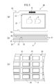
- the card 40 has a top sheet 10, a back sheet 20, an inlay 30, and a high-quality paper 31 laminated. These layers are adhered to each other by an adhesive layer 41 made of, for example, a hot melt of polyurethane.
- the inlay 30 is provided with an IC chip and an antenna 32.
- the woodfree paper 31 has a through hole 33 into which the IC chip is inserted.
- a card name N and a design G are printed on the topsheet 10, while another design (not shown) is printed on the backsheet 20. These patterns are repeatedly printed by the printing machine 100 (FIG. 1B) with n pieces as one cycle. Note that the design may be only characters or a registration mark.
- the laminated sheet 4 is formed of a first continuous sheet that is the top sheet 10 in FIG. 5B, a second continuous sheet that is the back sheet 20, a continuous sheet of the inlay 30 and the high-quality paper 31.
- the laminated sheet 4 of FIG. 5(c) is cut lengthwise and widthwise to form the card 40 of FIG. 5(a).
- registration marks R0 to R2 are provided with registration marks called registration marks R0 to R2 in FIG.
- the registration marks R0 to R2 are arranged in the center in the transport direction for convenience of description. For example, in the case of the topsheet 10 in FIG. 5, as shown in FIG. 5A, trimming is performed after stacking. And may be placed in a corner to be removed.
- FIG. 1A illustrates a case where the first and second continuous sheets 1 and 2 have a width corresponding to one card for convenience of drawing.
- a wide multi-row inlay 3A in which the inlays 30 are arranged vertically and horizontally and a continuous paper 3C of high-quality paper 31 are slit and conveyed in a plurality of single rows.
- the slitted single-row inlay 3B is cut into units of individual cards, and then each inlay 30 is attached to the continuous paper 3C of high-quality paper to form the intermediate sheet (reference sheet) 3.
- the first and second continuous sheets 1 and 2 are attached to the front and back of the intermediate sheet 3, respectively.
- the laminated sheet 4 in which the card 40 (FIG. 5A) is continuous is produced. Thereafter, the laminated sheet 4 is cut into individual cards 40.
- the continuous paper 3C in which the first and second continuous sheets 1 and 2, the multi-row inlay 3A, and the high-quality paper 31 (FIG. 5C) are continuous is wound from a drum. Will be issued.
- the multi-row inlay 3A of FIG. 2 When the multi-row inlay 3A of FIG. 2 is unwound from the drum, it is slit into a plurality of single-row inlays 3B by a slitter 60. Then, the slitted single-row inlays 3B are separated from each other in the width direction by a guider 61.
- the single-row inlay 3B is cut into individual card units by the first or second cutters 6A and 6B.
- the first and second cutters 6A, 6B contact the first and second anvils 7A, 7B, respectively, to cut each single row inlay 3B into individual card units.
- First and second suction conveyors 8A, 8B for intermittently supplying the single-row inlay 3B are arranged upstream of each cutter and anvil.
- the substantially rectangular inlay 30 (FIG. 5A) is intermittently conveyed on the arrangement drum 62 in a state of being arranged at a constant pitch.
- the adhesive is applied by the applicator 70 and then supplied to the placement drum 62.
- the arrangement drum 62 generates an intermediate sheet (reference sheet) 3 in which the inlay is intermittently arranged on the continuous paper 3C between the arrangement drum 62 and the nip roll 62N.
- the intermediate sheet 3 is supplied between the downstream nip rolls 63.
- a drive roll is generally used as one of the nip rolls 63, 63.
- the first and second continuous sheets 1 and 2 Prior to bonding, the first and second continuous sheets 1 and 2 are continuously supplied to the nip roll 63 as described below.
- the first and second continuous sheets 1 and 2 are unwound from a drum, and an adhesive is applied from an applicator 71, 72 to a back surface opposite to a surface on which a predetermined pattern is repeatedly printed.
- the first and second continuous sheets 1 and 2 are supplied to the first and second dancer rolls 81 and 82 on the downstream side, and are supplied to the nip roll 63 via these rolls.
- the dancer rolls 81 and 82 are reciprocated by an actuator 83 such as a servomotor to adjust the supply speed of the continuous sheets 1 and 2 to the nip roll 63.
- the continuous sheets 1 and 2 and the intermediate sheet 3 supplied to the nip rolls 63 and 63 are bonded to each other at the nip rolls 63 and 63, and the laminated sheet 4 is produced.
- the laminated sheet 4 is supplied to the trim cutter 64 and separated into the individual cards 40 and the lattice (frame)-shaped trimming sheet 4T.
- the card 40 is intermittently and continuously discharged and conveyed onto the belt conveyor 65.
- a sensor S0 for detecting a registration mark R0 (FIG. 4) provided on the inlay 30 is provided upstream of the nip roll 63.
- sensors S1 and S2 that detect registration marks R1 and R2 (FIG. 4) provided on the first and second continuous sheets 1 and 2 that are stacked are provided downstream of the nip roll 63.
- the first continuous sheet 1 and the second continuous sheet 2 have different designs, but the structure in which they are laminated on the intermediate sheet 3, the lamination method, and the control method are essentially the same. Therefore, in the following description, the case where the first continuous sheet 1 is laminated on the intermediate sheet 3 will be described as a representative, and the description regarding the lamination of the second continuous sheet 2 on the intermediate sheet 3 will be omitted.
- FIG. 3 shows an outline of the control system. As shown in this figure, the detection outputs of the sensors S0 to S2 are input to the control device 5.
- the control device 5 is composed of an electronic computer.
- the control device 5 includes a calculation unit such as the mark determination 50 and the counter 51, and a storage unit such as the threshold value of the displacement determination 52 and the driving amount 53.
- a display 54 and an operation unit 55 are connected to the control device 5.
- a part of the control device 5 and each of the sensors S0 to S2 constitute detection means for detecting the position of the symbol via the position of the registration mark as described below.
- the mark determination 50 detects each registration mark R0 to R2 by a signal from each sensor S0 to S2.
- the counter 51 counts the number of each of the registration marks R0 to R2, and when the number reaches a predetermined number, causes the deviation determination 52 to determine the degree of deviation as follows.
- the degree of the deviation amount D exceeds the first deviation range ⁇ 1 in FIG. 4A, it exceeds the allowable range ⁇ in FIG. 4B and is within the first deviation range ⁇ 1 and the allowable range in FIG. 4C. It is evaluated in 3 grades within the range ⁇ .
- the control device 5 of FIG. 3 reads T2 as the drive amount and shifts the displacement.
- the dancer roll 81 (82) is moved by T2 (for example, 2 mm) in the opposite direction to the moving direction. As a result, the large deviation is largely corrected. Such control will continue until the operating conditions stabilize.
- the control device 5 of FIG. Reads T1 as the driving amount, and moves the dancer roll 81 (82) by T1 (for example, 1 mm) in a direction opposite to the direction of deviation. As a result, the deviation is slightly corrected.
- the control device 5 of FIG. 4C when the deviation amount D is extremely small, that is, when the deviation amount D is within the predetermined allowable range ⁇ , the control device 5 of FIG.
- the displacement control of the dancer roll 81 (82) moves the dancer roll 81 (82) in the opposite direction to the movement direction by a very small amount. This will allow the dancer roll 81 (82) to approach the home position.
- the nip roll 63 is supplied with the reference sheet 3 that serves as a reference for alignment and the first continuous sheet 1 on which a predetermined pattern is repeatedly printed.
- the nip roll 63 forms the laminated sheet 4 by laminating the first continuous sheet 1 on the reference sheet 3.
- the control device 5 detects the presence of the registration mark by discriminating the registration mark R0 (FIG. 4) written on the single-row inlay 3B by the signal from the sensor S0. On the other hand, in the step after stacking, the control device 5 determines the registration mark R1 (FIG. 4) on the first continuous sheet 1 of the stacking sheet 4 by the signal from the sensor S1, that is, the registration mark R1 (FIG. 4). Detect the presence.
- the control device 5 determines whether or not the number of the registration marks has reached a predetermined period. If the number of judged registration marks is less than the predetermined n corresponding to the one cycle, the adjusting step is not executed, and the adjusting step is performed every time the number of marks reaches the predetermined n. That is, for each cycle, the control device 5 controls the supply speed of the first continuous sheet 1 (second continuous sheet 2) in FIG. 4 according to the result of the detection, and the first continuous sheet 1 (second continuous sheet 1). A first (second) adjusting step of adjusting the registration mark R1 of the continuous sheet 2) to a predetermined position with respect to the registration mark R0 of the reference sheet 3 is executed.
- the registration mark R1 (R2) of the first continuous sheet 1 (second continuous sheet 2) is larger than the registration mark R0 of the inlay 30 in the downstream X1 in the transport direction (first When the position is displaced (larger than the range ⁇ 1), the controller 5 of FIG. 3 moves the dancer roll 81 (82) toward the upstream side opposite to the downstream side X1 by, for example, 2 mm (a fixed amount).
- the dancer rolls 81 and 82 on which the first or second continuous sheets 1 and 2 are respectively wound are driven by the actuator 83 to drive the dancer rolls 81 and 82 shown in FIG.
- the first or second continuous sheet 1 or 2 is pulled in the direction in which the deviation amount D of a) decreases.
- the deviation amount D becomes smaller, and by repeating this control, the deviation amount D will eventually become smaller than the first range ⁇ 1 (FIG. 3).
- the control device 5 of FIG. 3 moves the dancer roll 81 (82) by a predetermined first constant amount T1 in the direction in which the position deviation becomes smaller, and then the first or the first deviation amount.
- the supply amount of the two continuous sheets 1 and 2 is changed, and the first or second adjusting step is executed.
- the registration mark R1 (R2) of the first continuous sheet 1 (second continuous sheet 2) is slightly displaced from the registration mark R0 of the inlay 30 in the downstream X1 in the transport direction. If so, the control device 5 in FIG. 3 moves the dancer roll 81 (82) toward the upstream side opposite to the downstream side X1 by, for example, 1 mm (a fixed amount).
- the shift amount D becomes smaller as described above, and by repeating this control, the shift amount D will eventually become smaller than the allowable range ⁇ .
- the control device 5 moves the dancer roll 81 (82) in FIG. 3 in a direction (downstream) X1 opposite to the direction (upstream) in which the dancer roll 81 (82) was moved last time by, for example, a small amount T (a fixed amount).
- the dancer roll 81 (82) is prevented from approaching the home position and being largely displaced from the home position. it can.
- the position of the symbol is determined based on the detection signal of the sensor S0, S1 or S2 of FIG. 2, the rotation of the trim cutter 64 is controlled according to the position of the symbol, and the cutting position when the card 40 is generated is Controlled.
- the registration marks R0 to R3 may be removed by trimming when the card 40 is cut out as shown in FIG. 5A.
- the difference in the phase is input to the control device 5 in advance, and the position adjusting process as described above is executed.
- the sensor S0 and the sensors S1 and S2 are separated from each other in the transport direction X. Therefore, the timing of detecting the registration mark corresponding to one specific card 40 is significantly different between the sensor S0 and the sensors S1 and S2. Therefore, in controlling the dancer roll, it is necessary to consider the timing deviation.
- the position adjustment of the sheets may be performed by controlling the tension of each sheet.
- the present invention can be applied to various card manufacturing methods such as a cash card.
Landscapes
- Engineering & Computer Science (AREA)
- Manufacturing & Machinery (AREA)
- Computer Hardware Design (AREA)
- Microelectronics & Electronic Packaging (AREA)
- Physics & Mathematics (AREA)
- General Physics & Mathematics (AREA)
- Theoretical Computer Science (AREA)
- Computer Networks & Wireless Communication (AREA)
- Credit Cards Or The Like (AREA)
- Controlling Rewinding, Feeding, Winding, Or Abnormalities Of Webs (AREA)
Abstract
Priority Applications (4)
| Application Number | Priority Date | Filing Date | Title |
|---|---|---|---|
| US17/427,139 US11878545B2 (en) | 2019-02-08 | 2019-12-16 | Card manufacturing method |
| EP19914236.5A EP3923194B1 (fr) | 2019-02-08 | 2019-12-16 | Procédé de fabrication de carte |
| JP2020571026A JP7391052B2 (ja) | 2019-02-08 | 2019-12-16 | カードの製造方法 |
| CN201980089707.5A CN113316789B (zh) | 2019-02-08 | 2019-12-16 | 卡的制造方法 |
Applications Claiming Priority (2)
| Application Number | Priority Date | Filing Date | Title |
|---|---|---|---|
| JP2019-021291 | 2019-02-08 | ||
| JP2019021291 | 2019-02-08 |
Publications (1)
| Publication Number | Publication Date |
|---|---|
| WO2020162045A1 true WO2020162045A1 (fr) | 2020-08-13 |
Family
ID=71947888
Family Applications (1)
| Application Number | Title | Priority Date | Filing Date |
|---|---|---|---|
| PCT/JP2019/049115 Ceased WO2020162045A1 (fr) | 2019-02-08 | 2019-12-16 | Procédé de fabrication de carte |
Country Status (5)
| Country | Link |
|---|---|
| US (1) | US11878545B2 (fr) |
| EP (1) | EP3923194B1 (fr) |
| JP (1) | JP7391052B2 (fr) |
| CN (1) | CN113316789B (fr) |
| WO (1) | WO2020162045A1 (fr) |
Citations (5)
| Publication number | Priority date | Publication date | Assignee | Title |
|---|---|---|---|---|
| JPH05105320A (ja) * | 1991-10-18 | 1993-04-27 | Toppan Printing Co Ltd | シートの貼合わせ装置 |
| JPH07276497A (ja) * | 1994-04-14 | 1995-10-24 | Dainippon Printing Co Ltd | 化粧シートの製造方法 |
| JPH11309969A (ja) | 1998-04-30 | 1999-11-09 | Konica Corp | 電子カード及びその製造方法 |
| JP2008279631A (ja) * | 2007-05-09 | 2008-11-20 | Miyakoshi Printing Machinery Co Ltd | 多重シートの生産装置 |
| JP2008308322A (ja) * | 2007-06-18 | 2008-12-25 | Toppan Forms Co Ltd | 連続用紙貼り合わせ装置 |
Family Cites Families (7)
| Publication number | Priority date | Publication date | Assignee | Title |
|---|---|---|---|---|
| TW381236B (en) * | 1995-07-07 | 2000-02-01 | Docusystem Inc | Integrated circuit chip card and the method and system for the manufacture same |
| US6086694A (en) * | 1997-04-01 | 2000-07-11 | Stanley Lerner | High speed web machine |
| JP2005014478A (ja) * | 2003-06-27 | 2005-01-20 | Toppan Printing Co Ltd | ロールシートラミネート方法及びラミネート装置 |
| JP4246020B2 (ja) * | 2003-09-08 | 2009-04-02 | 王子製紙株式会社 | 吸収性物品の製造方法 |
| US7544266B2 (en) * | 2004-05-21 | 2009-06-09 | Illinois Tool Works Inc. | Process of making laminated sheet and product made by the process |
| JP5103457B2 (ja) * | 2009-05-08 | 2012-12-19 | 株式会社トーツヤ・エコー | シートへの転写方法、転写装置、及びシート製品 |
| EP2572882B1 (fr) * | 2011-09-21 | 2014-07-16 | Bobst Grenchen Ag | Unité de laminage d'un premier lé sur un second dans une machine de contrecollage et procédé de fabrication d'un composite multicouches |
-
2019
- 2019-12-16 WO PCT/JP2019/049115 patent/WO2020162045A1/fr not_active Ceased
- 2019-12-16 CN CN201980089707.5A patent/CN113316789B/zh active Active
- 2019-12-16 EP EP19914236.5A patent/EP3923194B1/fr active Active
- 2019-12-16 US US17/427,139 patent/US11878545B2/en active Active
- 2019-12-16 JP JP2020571026A patent/JP7391052B2/ja active Active
Patent Citations (5)
| Publication number | Priority date | Publication date | Assignee | Title |
|---|---|---|---|---|
| JPH05105320A (ja) * | 1991-10-18 | 1993-04-27 | Toppan Printing Co Ltd | シートの貼合わせ装置 |
| JPH07276497A (ja) * | 1994-04-14 | 1995-10-24 | Dainippon Printing Co Ltd | 化粧シートの製造方法 |
| JPH11309969A (ja) | 1998-04-30 | 1999-11-09 | Konica Corp | 電子カード及びその製造方法 |
| JP2008279631A (ja) * | 2007-05-09 | 2008-11-20 | Miyakoshi Printing Machinery Co Ltd | 多重シートの生産装置 |
| JP2008308322A (ja) * | 2007-06-18 | 2008-12-25 | Toppan Forms Co Ltd | 連続用紙貼り合わせ装置 |
Also Published As
| Publication number | Publication date |
|---|---|
| US20220097992A1 (en) | 2022-03-31 |
| EP3923194A1 (fr) | 2021-12-15 |
| EP3923194B1 (fr) | 2025-04-02 |
| CN113316789B (zh) | 2024-12-20 |
| JPWO2020162045A1 (ja) | 2021-12-09 |
| CN113316789A (zh) | 2021-08-27 |
| JP7391052B2 (ja) | 2023-12-04 |
| US11878545B2 (en) | 2024-01-23 |
| EP3923194A4 (fr) | 2022-03-30 |
Similar Documents
| Publication | Publication Date | Title |
|---|---|---|
| JP4246020B2 (ja) | 吸収性物品の製造方法 | |
| US6409872B1 (en) | Identification card printer and laminator | |
| EP0260498B1 (fr) | Dispositif de contrôle de la position latérale d'une bande | |
| JPH07509574A (ja) | ラベルとその製造 | |
| US8770488B2 (en) | Method for the production of punched parts in web- or sheet-like print substrates and their further processing | |
| WO2019044062A1 (fr) | Procédé et dispositif de fabrication de corps d'emballage | |
| JP6642198B2 (ja) | 被加工物供給装置 | |
| JP5038173B2 (ja) | 印刷フイルムラミネート枚葉紙製造装置 | |
| JP7391052B2 (ja) | カードの製造方法 | |
| CA2187743C (fr) | Procede et dispositif permettant de reunir et de traiter des bandes de papier | |
| JP4866795B2 (ja) | 連続用紙貼り合わせ装置 | |
| US11590788B2 (en) | Sheet with feeding perforation | |
| JP5078789B2 (ja) | 積層シート作製機構 | |
| KR20230141101A (ko) | 시트상 제품의 제조 장치 및 방법 | |
| JP2007030178A (ja) | 段ボールシートの製造装置 | |
| JP4704879B2 (ja) | 製本装置 | |
| JP2004268365A (ja) | 熱プレス装置及び熱プレス方法 | |
| JP2024145279A (ja) | 複数の印刷装置を用いた印刷物の製造方法 | |
| JPS6241096A (ja) | Icカ−ドの作成方法 | |
| JP2015020431A (ja) | 情報通信体の製造方法 | |
| JP4704732B2 (ja) | 偽造防止シート製造装置 | |
| JP4495868B2 (ja) | 段ボールシートの反り防止装置 | |
| JP2003025475A (ja) | シート | |
| JP2000302293A (ja) | 紙葉類搬送装置、該紙葉類搬送装置を用いた印刷処理装置、紙葉類搬送方法及び印刷処理方法 | |
| JPH10217656A (ja) | カード製造方法及び製造装置 |
Legal Events
| Date | Code | Title | Description |
|---|---|---|---|
| 121 | Ep: the epo has been informed by wipo that ep was designated in this application |
Ref document number: 19914236 Country of ref document: EP Kind code of ref document: A1 |
|
| ENP | Entry into the national phase |
Ref document number: 2020571026 Country of ref document: JP Kind code of ref document: A |
|
| NENP | Non-entry into the national phase |
Ref country code: DE |
|
| ENP | Entry into the national phase |
Ref document number: 2019914236 Country of ref document: EP Effective date: 20210908 |
|
| WWG | Wipo information: grant in national office |
Ref document number: 2019914236 Country of ref document: EP |