WO2020162154A1 - Dispositif de traitement d'informations et procédé de traitement d'informations - Google Patents
Dispositif de traitement d'informations et procédé de traitement d'informations Download PDFInfo
- Publication number
- WO2020162154A1 WO2020162154A1 PCT/JP2020/001795 JP2020001795W WO2020162154A1 WO 2020162154 A1 WO2020162154 A1 WO 2020162154A1 JP 2020001795 W JP2020001795 W JP 2020001795W WO 2020162154 A1 WO2020162154 A1 WO 2020162154A1
- Authority
- WO
- WIPO (PCT)
- Prior art keywords
- user
- image
- information processing
- display
- pointing
- Prior art date
- Legal status (The legal status is an assumption and is not a legal conclusion. Google has not performed a legal analysis and makes no representation as to the accuracy of the status listed.)
- Ceased
Links
Images













Classifications
-
- G—PHYSICS
- G06—COMPUTING OR CALCULATING; COUNTING
- G06F—ELECTRIC DIGITAL DATA PROCESSING
- G06F3/00—Input arrangements for transferring data to be processed into a form capable of being handled by the computer; Output arrangements for transferring data from processing unit to output unit, e.g. interface arrangements
- G06F3/01—Input arrangements or combined input and output arrangements for interaction between user and computer
- G06F3/011—Arrangements for interaction with the human body, e.g. for user immersion in virtual reality
-
- G—PHYSICS
- G06—COMPUTING OR CALCULATING; COUNTING
- G06F—ELECTRIC DIGITAL DATA PROCESSING
- G06F3/00—Input arrangements for transferring data to be processed into a form capable of being handled by the computer; Output arrangements for transferring data from processing unit to output unit, e.g. interface arrangements
- G06F3/14—Digital output to display device ; Cooperation and interconnection of the display device with other functional units
- G06F3/1454—Digital output to display device ; Cooperation and interconnection of the display device with other functional units involving copying of the display data of a local workstation or window to a remote workstation or window so that an actual copy of the data is displayed simultaneously on two or more displays, e.g. teledisplay
-
- G—PHYSICS
- G06—COMPUTING OR CALCULATING; COUNTING
- G06F—ELECTRIC DIGITAL DATA PROCESSING
- G06F3/00—Input arrangements for transferring data to be processed into a form capable of being handled by the computer; Output arrangements for transferring data from processing unit to output unit, e.g. interface arrangements
- G06F3/01—Input arrangements or combined input and output arrangements for interaction between user and computer
- G06F3/017—Gesture based interaction, e.g. based on a set of recognized hand gestures
-
- G—PHYSICS
- G06—COMPUTING OR CALCULATING; COUNTING
- G06F—ELECTRIC DIGITAL DATA PROCESSING
- G06F3/00—Input arrangements for transferring data to be processed into a form capable of being handled by the computer; Output arrangements for transferring data from processing unit to output unit, e.g. interface arrangements
- G06F3/01—Input arrangements or combined input and output arrangements for interaction between user and computer
- G06F3/03—Arrangements for converting the position or the displacement of a member into a coded form
- G06F3/0304—Detection arrangements using opto-electronic means
-
- G—PHYSICS
- G06—COMPUTING OR CALCULATING; COUNTING
- G06F—ELECTRIC DIGITAL DATA PROCESSING
- G06F3/00—Input arrangements for transferring data to be processed into a form capable of being handled by the computer; Output arrangements for transferring data from processing unit to output unit, e.g. interface arrangements
- G06F3/01—Input arrangements or combined input and output arrangements for interaction between user and computer
- G06F3/03—Arrangements for converting the position or the displacement of a member into a coded form
- G06F3/041—Digitisers, e.g. for touch screens or touch pads, characterised by the transducing means
- G06F3/042—Digitisers, e.g. for touch screens or touch pads, characterised by the transducing means by opto-electronic means
- G06F3/0425—Digitisers, e.g. for touch screens or touch pads, characterised by the transducing means by opto-electronic means using a single imaging device like a video camera for tracking the absolute position of a single or a plurality of objects with respect to an imaged reference surface, e.g. video camera imaging a display or a projection screen, a table or a wall surface, on which a computer generated image is displayed or projected
-
- G—PHYSICS
- G06—COMPUTING OR CALCULATING; COUNTING
- G06F—ELECTRIC DIGITAL DATA PROCESSING
- G06F3/00—Input arrangements for transferring data to be processed into a form capable of being handled by the computer; Output arrangements for transferring data from processing unit to output unit, e.g. interface arrangements
- G06F3/01—Input arrangements or combined input and output arrangements for interaction between user and computer
- G06F3/048—Interaction techniques based on graphical user interfaces [GUI]
- G06F3/0484—Interaction techniques based on graphical user interfaces [GUI] for the control of specific functions or operations, e.g. selecting or manipulating an object, an image or a displayed text element, setting a parameter value or selecting a range
- G06F3/04845—Interaction techniques based on graphical user interfaces [GUI] for the control of specific functions or operations, e.g. selecting or manipulating an object, an image or a displayed text element, setting a parameter value or selecting a range for image manipulation, e.g. dragging, rotation, expansion or change of colour
-
- G—PHYSICS
- G06—COMPUTING OR CALCULATING; COUNTING
- G06F—ELECTRIC DIGITAL DATA PROCESSING
- G06F3/00—Input arrangements for transferring data to be processed into a form capable of being handled by the computer; Output arrangements for transferring data from processing unit to output unit, e.g. interface arrangements
- G06F3/01—Input arrangements or combined input and output arrangements for interaction between user and computer
- G06F3/048—Interaction techniques based on graphical user interfaces [GUI]
- G06F3/0487—Interaction techniques based on graphical user interfaces [GUI] using specific features provided by the input device, e.g. functions controlled by the rotation of a mouse with dual sensing arrangements, or of the nature of the input device, e.g. tap gestures based on pressure sensed by a digitiser
- G06F3/0488—Interaction techniques based on graphical user interfaces [GUI] using specific features provided by the input device, e.g. functions controlled by the rotation of a mouse with dual sensing arrangements, or of the nature of the input device, e.g. tap gestures based on pressure sensed by a digitiser using a touch-screen or digitiser, e.g. input of commands through traced gestures
- G06F3/04883—Interaction techniques based on graphical user interfaces [GUI] using specific features provided by the input device, e.g. functions controlled by the rotation of a mouse with dual sensing arrangements, or of the nature of the input device, e.g. tap gestures based on pressure sensed by a digitiser using a touch-screen or digitiser, e.g. input of commands through traced gestures for inputting data by handwriting, e.g. gesture or text
-
- H—ELECTRICITY
- H04—ELECTRIC COMMUNICATION TECHNIQUE
- H04N—PICTORIAL COMMUNICATION, e.g. TELEVISION
- H04N7/00—Television systems
- H04N7/14—Systems for two-way working
- H04N7/141—Systems for two-way working between two video terminals, e.g. videophone
Definitions
- the present disclosure relates to an information processing device and an information processing method, and more particularly, to an information processing device and an information processing method capable of providing a better user experience.
- asymmetric display control a person or an object in a captured image is separated from the background, the position or size of the person or the object is reconstructed, and the result is presented to one user side. It is possible to perform processing.
- Patent Document 1 discloses a technique of synthesizing a motion transition image by separating a moving subject layer and a background layer in the image for frame image data.
- the present disclosure has been made in view of such a situation, and is intended to provide a better user experience.
- a first information processing device is a result of sensing any one of the users when at least two users communicate with each other while viewing each other's images transmitted and received via a network.
- An information processing unit that performs information processing that makes the presentation content presented by one of the user sides different from that of the other user side based on the detection result obtained as.
- the information processing method can be obtained as a result of sensing one of the users when at least two users communicate while viewing each other's images transmitted and received via a network. Based on the detection result, information processing is performed to make the presentation content presented by one of the user sides different from that of the other user side.
- a second information processing apparatus communicates with a terminal used for communication while at least two users view images of each other transmitted and received via a network, and An information processing unit that performs information processing that makes the presentation content presented by one of the users different from that of the other user based on the detection result obtained as a result of sensing the user. ..
- At least two users communicate with a terminal used for communication while viewing each other's images transmitted and received via a network, and sense one of the users. Based on the detection result obtained as a result, information processing is performed in which the presentation content presented by one of the user sides is different from that of the other user side.
- FIG. 20 is a block diagram illustrating a configuration example of an embodiment of a computer to which the present technology is applied.
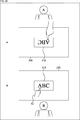
- FIG. 1 is a block diagram showing a configuration example of a first embodiment of a remote communication system to which the present technology is applied.
- the remote communication system 11 is configured by connecting communication terminals 13A and 13B at remote locations via a network 12 such as the Internet.
- the communication terminals 13A and 13B perform remote communication through the network 12 so that images and sounds can be transmitted and received in real time to each other.
- the user A on the communication terminal 13A side and the user B on the communication terminal 13B side can talk as if they are facing each other, and more realistic communication can be achieved.
- the communication terminals 13A and 13B are similarly configured, and when it is not necessary to distinguish them, the communication terminals 13A and 13B are simply referred to as the communication terminal 13, and the respective units configuring the communication terminals 13A and 13B are also similarly referred to. Further, of the communication processes performed by the communication terminal 13, only the process related to images will be described below, and the description of the process related to voice will be omitted.
- the communication terminal 13 includes a camera 21, a projector unit 22, a display unit 23, a desk type screen 24, and a communication processing unit 25.
- the camera 21 captures an image in front of the display unit 23, and supplies an image signal obtained by capturing an image of a user facing the display unit 23 to the communication processing unit 25, for example.
- the projector unit 22 has a projector main body 31, a stereo camera 32, and an RGB camera 33 built therein.
- the projector main body 31, the stereo camera 32, and the RGB camera 33 may be configured as separate units.
- the projector main body 31 projects various images such as the document image 41 and the pointing image 42 on the desk screen 24 according to the display control signal supplied from the communication processing unit 25, and displays these images.
- the stereo camera 32 acquires the depth signal indicating the depth direction of the object such as the user's hand on the desk type screen 24 by using the parallax of the two image pickup devices, and supplies the depth signal to the communication processing unit 25.
- the RGB camera 33 captures an image toward the desk type screen 24 and supplies an image signal obtained by capturing an image of an object such as a user's hand on the desk type screen 24 to the communication processing unit 25.
- the display unit 23 is configured to include a display device such as a liquid crystal panel or an organic EL (Electro Luminescence) panel, and based on a display control signal supplied from the communication processing unit 25, for example, a user on the other side is displayed. Images, etc. are displayed.
- a display device such as a liquid crystal panel or an organic EL (Electro Luminescence) panel
- the desk-type screen 24 has a function as a screen for clearly displaying an image projected from the projector unit 22 on a desk on which an object is placed or work is performed.
- the communication processing unit 25 performs communication processing for enabling mutual communication between users via the network 12. For example, when the user A makes a pointing gesture to point to a predetermined pointing portion of the document image 41A, the communication processing unit 25 displays the pointing image 42 to point to the corresponding pointing portion of the document image 41B. Processing can be performed.
- the remote communication system 11 can communicate as if the user A and the user B are facing each other.
- the user A uses the document image 41 to explain to the user B. It can be used for such purposes. Therefore, hereinafter, the user A of the communication terminal 13A is also referred to as an explainer, and the user B of the communication terminal 13B is also referred to as a customer.
- the remote communication system 11 the pointing image 42 is displayed on the document image 41B according to the pointing gesture of the user A on the document image 41A, so that the point where the user A is explaining is recognized by the user B. Can be easily performed. Thereby, the remote communication system 11 can provide a better user experience by providing a smoother explanation.
- FIG. 2 is a block diagram showing a configuration example of the communication processing unit 25.
- the communication processing unit 25 includes an input unit 51, an output unit 52, an operation input unit 53, a storage unit 54, a communication unit 55, and a control unit 56.
- the input unit 51 is an interface for inputting an image signal output from the camera 21, a depth signal output from the stereo camera 32, an image signal output from the RGB camera 33, and the like to the communication processing unit 25. Is supplied to the control unit 56.
- the output unit 52 is an interface for outputting the display control signal supplied from the control unit 56 to each of the projector body 31 and the display unit 23.
- the operation input unit 53 is an interface for inputting an operation signal according to a user operation to an operation unit (for example, a keyboard, a mouse, a touch panel, etc.) not shown, and supplies the operation signal to the control unit 56.
- an operation unit for example, a keyboard, a mouse, a touch panel, etc.
- the storage unit 54 stores various data required for the control unit 56 to control the communication processing unit 25, image data for displaying the document image 41 or the pointing image 42, and the like.
- the communication unit 55 has a transmission unit 61 and a reception unit 62, and communicates with the communication terminal 13 on the partner side via the network 12 of FIG.
- the transmission unit 61 transmits the data supplied from the control unit 56 to the communication terminal 13 on the other side
- the reception unit 62 receives the data transmitted from the communication terminal 13 on the other side. And supplies it to the control unit 56.
- the control unit 56 includes a detection result acquisition unit 71, an information processing unit 72, and a display control unit 73, and controls the communication processing unit 25 to execute communication processing.
- the detection result acquisition unit 71 detects, for example, the movement of the user's hand on the desk screen 24 based on the depth signal output from the stereo camera 32 and the image signal output from the RGB camera 33, The detection result is acquired. At this time, the detection result acquisition unit 71 may perform a process of removing noise of those signals. Similarly, the detection result acquisition unit 71 detects a shared object 44 described later with reference to FIG. 9, an arbitrary object 45 described later with reference to FIG. 11, and acquires the detection results thereof.
- the information processing unit 72 performs information processing (analysis for making the image displayed on the user B side different from the image displayed on the user A side based on the detection result acquired by the detection result acquisition unit 71). And processing such as adjustment). Then, the information processing section 72 transmits various data (for example, image data, position information, coordinate information, etc., which will be described later) that need to be transmitted to the communication terminal 13 on the partner side in order to execute the communication processing, to the communication section. Via 55.
- the display control unit 73 acquires the image data transmitted from the communication terminal 13 of the other party via the communication unit 55, and according to the image data, displays the image of the user of the other party, for example. , And performs display control on the display unit 23. Further, the display control unit 73 reads out image data from the storage unit 54 and performs display control on the projector main body 31 so as to display the document image 41 or the pointing image 42 at an appropriate display position.
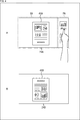
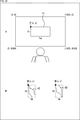
- FIG. 3A and FIG. 4A show an example of the situation on the desk-type screen 24A on the side of the user A who is the explainer, and FIG. 3B and FIG. 4B show the customer. An example of the situation on the desk type screen 24B on the user B side is shown.
- the shared area SA and the private area PA are set on the desk type screen 24A on the user A side.
- the shared area SA an image shared with the user B is displayed.
- the document image 41A is displayed on the desk type screen 24B on the user B side.
- an image not shared with the user B is displayed in the private area PA, and the image displayed in the private area PA is not displayed on the desk-type screen 24B on the user B side.
- the user A makes a pointing gesture so as to point to a predetermined pointing portion of the document image 41A displayed in the shared area SA of the desk type screen 24A.
- the pointing image 42 is displayed so as to point to the corresponding pointing portion of the document image 41B.
- the user A points to an image (for example, a user interface for performing an operation) displayed in the private area PA of the desk type screen 24A.
- the pointing image 42 is not displayed on the desk type screen 24B on the user B side. That is, display control is performed so that the image displayed in the private area PA and the movement of the hand of the user A in the private area PA cannot be seen from the user B side.
- the pointing image 42 is displayed in the document image 41B and the private area PA is pointed. If so, the pointing image 42 is hidden.
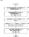
- FIG. 5 shows a flowchart explaining the first communication process.
- the operation signal is supplied to the control unit 56A via the operation input unit 53A of the communication processing unit 25A. The process is started.
- step S11 in the communication processing unit 25A, the display control unit 73A reads the image data of the document instructed by the user from the storage unit 54A and displays the document image 41A in the shared area SA of the desk type screen 24A. Display control for the projector main body 31A is performed. Then, the information processing unit 72A acquires the image data of the document image 41A displayed in the shared area SA and the position information indicating the display position of the document image 41A on the desk type screen 24A, and communicates via the communication unit 55A. It is transmitted to the processing unit 25B.
- step S12 in the communication processing unit 25B, the display control unit 73B displays the document image 41B on the desk screen 24B, similar to the document image 41A, based on the image data and the position information acquired via the communication unit 55B. Display control for the projector main body 31B is performed as described above. In response to this, the projector main body 31B displays the document image 41B having the same content as the document image 41A on the desk screen 24B according to the image data so that the display position is in accordance with the position information.
- step S13 in the communication processing unit 25A, the detection result acquisition unit 71A causes the user on the desk type screen 24A to detect the depth signal based on the depth signal output from the stereo camera 32A and the image signal output from the RGB camera 33A. The movement of A's hand is detected, and the detection result is supplied to the information processing unit 72A. Then, the information processing unit 72A recognizes the movement of the hand of the user A according to the detection result of the movement of the hand of the user A, and determines whether the user A has made a pointing gesture.
- step S13 If the information processing unit 72A determines in step S13 that the user A has made a pointing gesture, the process proceeds to step S14.
- step S14 in the communication processing unit 25A, the detection result acquisition unit 71A detects the position of the fingertip of the user A based on the depth signal output from the stereo camera 32A and the image signal output from the RGB camera 33A. Then, the detection result is supplied to the information processing section 72A. Then, the information processing unit 72A acquires the pointing coordinates indicating the coordinates of the instruction point designated by the user A by the pointing gesture on the desk type screen 24A according to the detection result of the position of the fingertip of the user A.
- step S15 the information processing section 72A determines whether or not the pointing coordinates acquired in step S14 are within the shared area SA.
- step S15 If the information processing section 72A determines in step S15 that the pointing coordinates are within the shared area SA, the process proceeds to step S16.
- step S16 in the communication processing unit 25A, the information processing unit 72A transmits the coordinate information indicating the pointing coordinates to the communication processing unit 25B via the communication unit 55A. Then, in the communication processing unit 25B, the display control unit 73B controls the projector main body 31B so as to display the pointing image 42 in an arrangement pointing to the pointing coordinates according to the coordinate information acquired via the communication unit 55B. In response to this, the projector main body 31B displays the pointing image 42 on the desk-type screen 24B so as to point to the point designated by the user A, and then the process ends.
- step S13 when it is determined in step S13 that the user A is not performing the pointing gesture, or when it is determined in step S15 that the pointing coordinates are not within the shared area SA, the pointing image 42 is not displayed, The process ends.
- the pointing image 42 can be displayed when the inside of the shared area SA is pointed in accordance with the pointing gesture of the user A, and the user A is smoother. Can be explained.
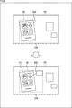
- FIG. 6 shows an example of the situation on the desk-type screen 24A on the side of the user A who is the explainer.
- the shared area SA and the private area PA are fixedly set on the desk type screen 24A on the user A side.
- the shared area SA can be dynamically set.
- the shared area SA is set according to the size and orientation of the document image 41A. It Then, the area other than the shared area SA is set as the private area PA on the desk type screen 24A. In the illustrated example, the outline rectangles of the shared area SA and the private area PA are set so as to follow the outer shape of the desk screen 24A.
- a rectangular shared area SA that surrounds the document image 41A is set.
- the shared area SA is updated to have a rectangular outline that surrounds the document image 41A and the related information image 43A.
- a connection line that connects the item described in the document image 41A and the related information image 43A is displayed.
- the document image 41B and the related information image 43B are displayed on the desk-type screen 24B, similarly to the document image 41A and the related information image 43A displayed in the shared area SA. become.
- the shared area SA is updated so as to return to the original state as shown in the upper side of FIG.
- the size of the shared area SA is changed according to the size and number of images that the user A wants to share with the user B.
- FIG. 7 shows a flowchart explaining the second communication process.
- the display control unit 73A performs display control to display the document image 41A on the desk screen 24A in response to the operation of the user A, the process is started.
- step S21 in the communication processing unit 25A, the information processing unit 72A creates a rectangular outline shared area SA that surrounds the document image 41A displayed on the desk type screen 24A according to the display control of the display control unit 73A. Set. Then, the information processing unit 72A uses, as the shared area coordinates defining the shared area SA, for example, the upper left coordinate P1 (X0, Y0) and the lower right coordinate P2 (X1, Y1) of the shared area SA as shown in the upper side of FIG. ) To get.
- the shared area coordinates defining the shared area SA for example, the upper left coordinate P1 (X0, Y0) and the lower right coordinate P2 (X1, Y1) of the shared area SA as shown in the upper side of FIG. )
- step S22 in the communication processing unit 25A, the detection result acquisition unit 71A causes the user on the desk-type screen 24A to select the depth signal output from the stereo camera 32A and the image signal output from the RGB camera 33A.
- the movement of A's hand is detected, and the detection result is supplied to the information processing unit 72A.
- the information processing unit 72A recognizes the movement of the hand of the user A according to the detection result of the movement of the hand of the user A, and determines whether the user A has performed the tap gesture for the item of the document image 41A.
- step S22 determines in step S22 that the user A has performed the tap gesture
- the process proceeds to step S23.
- the process is on standby in step S22.
- step S23 in the communication processing unit 25A, the display control unit 73A reads from the storage unit 54A the image data for displaying the related information related to the item for which the tap gesture is performed by the user. Then, the display control unit 73A controls the projector body 31A to display the related information image 43A based on the image data outside the shared area SA, and the projector body 31A displays the related information image 43A on the desk type screen 24A. To do.
- step S24 in the communication processing unit 25A, the information processing unit 72A acquires contour coordinates including the document image 41A and the related information image 43A displayed on the desk screen 24A.
- step S25 in the communication processing unit 25A, the information processing unit 72A updates the contour coordinates acquired in step S24 as the shared area coordinates that define the shared area SA.
- the information processing unit 72A sets the upper left coordinates P1 (X2, Y2) and the lower right coordinates P2 (X3, Y3) of the shared area SA as shown in the lower side of FIG. 8 as the shared area coordinates that define the shared area SA.
- FIG. 8 shows a display example in which two related information images 43-1 and 43-2 are displayed.
- step S25 After the processing of step S25, the processing returns to step S22, and the same processing is repeated thereafter.
- the shared area SA can be dynamically expanded so that the related information is shared with the user B in accordance with the tap gesture of the user A, for example.
- FIG. 9 shows an example of the situation on the desk-type screen 24A on the side of the user A who is the explainer.
- the shared area SA is dynamically set based on the image displayed on the desk type screen 24A.
- the shared area SA can be dynamically set based on the shared object placed on the desk-shaped screen 24A instead of the image.
- the shared object 44 is recognized by image recognition using a marker or the like, for example.
- the shared area SA has a rectangular shape that surrounds the one shared object 44 inside. Is set.
- the two shared objects 44-1 and 44-2 are placed.
- the shared area SA having a rectangular outline that surrounds the inside is updated.
- the size of the shared area SA is changed according to the size and the number of the shared objects 44 that the user A wants to share with the user B.
- FIG. 10 shows a flowchart explaining the third communication process.
- step S31 in the communication processing unit 25A, the information processing unit 72A sets a rectangular shared area SA that surrounds the shared object 44 placed on the desk type screen 24A by the user A inside. Then, the information processing unit 72A acquires the shared area coordinates that define the shared area SA, as in step S21 of FIG. 7.
- step S32 in the communication processing unit 25A, the detection result acquisition unit 71A shares the desk-shaped screen 24A based on the depth signal output from the stereo camera 32A and the image signal output from the RGB camera 33A.
- the object 44 is detected and the detection result is supplied to the information processing section 72A.
- the information processing unit 72A determines whether a change (addition or reduction) of the shared object 44 is detected according to the detection result of the shared object 44.
- step S32 determines in step S32 that a change in the shared object 44 has been detected. If the information processing unit 72A determines in step S32 that a change in the shared object 44 has been detected, the process proceeds to step S33. When the information processing unit 72A determines that the change of the shared object 44 has not been detected, the process waits in step S32.
- step S33 in the communication processing unit 25A, the information processing unit 72A acquires the contour coordinates including all the shared objects 44 placed on the desk type screen 24A.
- step S34 in the communication processing unit 25A, the information processing unit 72A updates the contour coordinates acquired in step S33 as the shared area coordinates defining the shared area SA, as in step S25 of FIG.
- the shared area SA is enlarged, and when it is detected that the shared object 44 has been reduced, the shared area SA is reduced.
- step S34 After the processing of step S34, the processing returns to step S32, and the same processing is repeated thereafter.
- the shared area SA can be dynamically expanded or reduced according to the addition or reduction of the shared object 44 placed in the shared object 44.
- FIG. 11A shows an example of the situation on the desk-type screen 24A on the side of the user A who is the explainer
- FIG. 11B shows on the desk-type screen 24B on the side of the user B who is the customer. An example of the situation is shown.
- the document image 41B was displayed on the desk screen 24B in correspondence with the display position of the document image 41A on the desk screen 24A.
- the display position of the document image 41B can be adjusted according to the object placed on the desk screen 24B.
- the object 45 is displayed on the desk-shaped screen 24B when it is made to correspond to the display position of the document image 41A shown in A of FIG.
- the document images 41B are displayed so as to overlap each other. Therefore, the empty space in which the object 45 is not placed is detected, and the document image 41B is displayed in the empty space.
- the display position of the pointing image 42 is also adjusted in accordance with the adjustment of the display position of the document image 41B.
- the document image 41B is displayed according to the object 45 placed on the desk type screen 24B so as not to overlap the object 45.
- FIG. 12 shows a flowchart explaining the fourth communication process.
- the operation signal is supplied to the control unit 56A via the operation input unit 53A of the communication processing unit 25A. The process is started.
- step S41 in the communication processing unit 25A, the display control unit 73A reads the image data of the document instructed by the user from the storage unit 54A and displays the document image 41A in the shared area SA of the desk type screen 24A. Display control for the projector main body 31A is performed. Then, the information processing unit 72A acquires the image data of the document image 41A displayed in the shared area SA and the position information indicating the display position of the document image 41A on the desk type screen 24A, and communicates via the communication unit 55A. It is transmitted to the processing unit 25B.
- step S42 in the communication processing unit 25B, the detection result acquisition unit 71B is placed on the desk type screen 24B based on the depth signal output from the stereo camera 32B and the image signal output from the RGB camera 33B.
- the detected object 45 is detected, and the detection result is supplied to the information processing section 72B.
- the information processing unit 72B acquires the outline coordinates of the outline that is a rectangle surrounding the object 45 based on the detection result supplied from the information processing unit 72B.
- step S43 in the communication processing unit 25B, the information processing unit 72B recognizes an area other than the area where the object 45 is placed on the desk type screen 24B as an empty space based on the contour coordinates of the object 45 acquired in step S42. To do.
- step S44 the information processing unit 72B determines whether the empty space recognized in step S43 is smaller than the actual size of the document image 41B.
- step S44 determines in step S44 that the empty space is smaller than the actual size of the document image 41B. If the information processing unit 72B determines in step S44 that the empty space is smaller than the actual size of the document image 41B, the process proceeds to step S45.
- step S45 in the communication processing unit 25B, the display control unit 73B performs image processing for reducing the document image 41B in accordance with the size of the empty space recognized by the information processing unit 72B.
- step S45 After the process of step S45, or when it is determined in step S44 that the empty space is not smaller than the actual size of the document image 41B (that is, the empty space is larger than the actual size of the document image 41B), the process proceeds to step S46. ..
- step S46 in the communication processing unit 25B, the display control unit 73B controls the display of the projector body 31B so as to display the document image 41B in the empty space where the object 45 is not placed on the desk type screen 24B.
- the projector main body 31B displays the document image 41B having the same content as the document image 41A in the empty space of the desk type screen 24B.
- step S45 the document image 41B is reduced and displayed, and if the process of step S45 is not being performed, the document image 41B is displayed in the actual size. In this way, after the projector main body 31B displays the document image 41B in the empty space, the process ends.
- the position and the size when the document image 41B is displayed are adjusted according to the object placed on the desk screen 24B.
- the display of the pointing image 42 is appropriately adjusted when the pointing gesture of the user A passes through the private area PA.
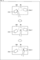
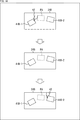
- FIG. 13 shows how user A moves his hand while pointing and making a gesture.
- the private area PA is set between the document image 41A-1 and the document image 41A-2
- the user A points to the document image 41A-1, but subsequently the document image 41A-
- an operation of pointing 2 is performed.
- the display control is performed so that the pointing image 42 is hidden as described above.
- either one of the first display control as described with reference to FIG. 14 and the second display control as described with reference to FIG. 15 is performed.
- the display of the pointing image 42 is controlled so as to be hidden while the fingertip of the user A passes through the private area PA. .. That is, in the second display control of the pointing image 42, display control is performed so that the pointing image 42 is displayed at the edge of the document image 41A-2 after disappearing at the edge of the document image 41A-1.
- the updating of the display of the pointing image 42 is stopped when the fingertip of the user A is separated from the document image 41A-1, and the fingertip of the user A is stopped.
- the display of the pointing image 42 is controlled so as to update the display. That is, in the second display control of the pointing image 42, display control is performed so that the pointing image 42 stopped at the edge of the document image 41A-1 momentarily moves to the edge of the document image 41A-2. ..
- FIG. 16 shows a flowchart illustrating the fifth communication process in which the first display control as described with reference to FIG. 14 is performed.
- steps S51 to S55 the same processing as steps S11 to S15 in FIG. 5 is performed. Then, in step S55, when the information processing unit 72A determines that the pointing coordinates are within the shared area SA, the process proceeds to step S56.
- step S56 in the communication processing unit 25B, the display control unit 73B controls the projector main body 31B to update the display of the pointing image 42 in the arrangement indicating the pointing coordinates according to the coordinate information transmitted from the communication processing unit 25A. Control. In response to this, the projector main body 31B updates the pointing image 42 displayed on the desk-type screen 24B so as to point to the point designated by the user A, and then the process ends.
- step S53 determines whether the user A is performing the pointing gesture, or if it is determined in step S55 that the pointing coordinates are not within the shared area SA. If it is determined in step S53 that the user A is not performing the pointing gesture, or if it is determined in step S55 that the pointing coordinates are not within the shared area SA, the process proceeds to step S57.
- step S57 in the communication processing unit 25B, the display control unit 73B controls the projector body 31B so as to erase the display of the pointing image 42. In response to this, the projector main body 31B erases the display of the pointing image 42, and then the process ends.
- FIG. 17 shows a flowchart illustrating the fifth communication process in which the second display control as described with reference to FIG. 15 is performed.
- steps S61 to S67 the same processing as steps S51 to S57 in FIG. 16 is performed.
- the process proceeds to step S68.
- step S68 in the communication processing unit 25B, the display control unit 73B controls the projector body 31B so as to stop updating the display of the pointing image 42.
- the projector main body 31B continues to display the pointing image 42 at the position displayed when it is determined that the pointing coordinates are not within the shared area SA, and then the process ends.
- the document image 41A- The pointing image 42 is displayed as if it stopped at the end of 1.
- the display of the document image 41 and the pointing image 42 is controlled in the first to third display cases assumed when the user A and the user B perform the remote collaborative work. ..
- the reference vertical direction when displaying the document image 41 and the pointing image 42 on the desk type screen 24 is set such that the back side as viewed from the user is the upward direction and the front side as viewed from the user is the downward direction.
- the vertical direction of the document image 41 is set, for example, according to the orientation of the characters of the description content, and the vertical direction of the finger pointing image 42 is set with the fingertip upward and the hand downward.
- the back side as viewed from the user is the side on which the display unit 23 is arranged, as shown in FIG.
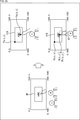
- the first display case is an image of user A facing user B, and is applied when user A arranges a document so as to face user B and gives an explanation. That is, as shown in A of FIG. 18, on the communication terminal 13A side, the document is displayed on the desk-type screen 24A so that it is rotated 180 degrees with respect to the reference vertical direction so that the back side is downward when viewed from the user A. The image 41A is displayed. Further, as shown in FIG. 18B, on the communication terminal 13B side, the document image 41B is displayed on the desk-type screen 24B so that the front side as viewed from the user B is downward according to the reference vertical direction.
- the pointing image 42 is displayed as if the user A were facing the user B, and the back side when viewed from the user B was the hand. That is, as shown in B of FIG. 18, by rotating 180 degrees with respect to the vertical direction of the reference, the back side as viewed from the user B is the hand, and the fingertip is directed with the fingertip toward the front side as viewed from the user B. As shown, the pointing image 42 is displayed on the desk-shaped screen 24B. Therefore, the pointing image 42 is displayed with respect to the document image 41B in the same manner as the direction of the hand of the user A with respect to the document image 41A and the lateral movement.
- the second display case is an image of user A facing user B, and is applied when user A arranges a document so as to face itself and gives an explanation. That is, as shown in A of FIG. 19, on the communication terminal 13A side, the document image 41A is displayed on the desk-type screen 24A so that the front side of the user A faces downward according to the reference vertical direction. Further, as shown in B of FIG. 19, on the communication terminal 13B side, the document image 41B is displayed on the desk-type screen 24B such that the front side as viewed from the user B is downward according to the reference vertical direction.
- the pointing image 42 is displayed as if the user A were facing the user B, and the back side when viewed from the user B was the hand. That is, as shown in B of FIG. 19, by rotating 180 degrees with respect to the vertical direction of the reference, the back side as viewed from the user B is the hand, and the fingertip is directed with the fingertip toward the front side as viewed from the user B. As shown, the pointing image 42 is displayed on the desk-shaped screen 24B. Therefore, the pointing image 42 is displayed with respect to the document image 41B so as to rotate by 180 degrees with respect to the orientation of the hand of the user A with respect to the document image 41A and the lateral movement.
- the third display case is applied when user A arranges a document so that user A faces user B and arranges the document so as to face himself. That is, as shown in FIG. 20A, on the communication terminal 13A side, the document image 41A is displayed on the desk-type screen 24A so that the front side as viewed from the user A is downward according to the reference vertical direction. Further, as shown in FIG. 20B, on the communication terminal 13B side, the document image 41B is displayed on the desk-type screen 24B so that the front side as viewed from the user B is downward according to the reference vertical direction.
- the pointing image 42 is displayed so that the user A is close to the user B, and the front side of the user B is displayed at hand. That is, as shown in B of FIG. 19, according to the vertical direction of the reference, the front side when viewed from the user B is the hand, and the fingertip is pointed toward the back side when viewed from the user B, and the desk type is used.
- the pointing image 42 is displayed on the screen 24B. Therefore, the pointing image 42 is displayed with respect to the document image 41B in the same manner as the direction of the hand of the user A with respect to the document image 41A and the lateral movement.
- the display area size (width 1920, height 1080) indicating the size of the display area that the projector body 31 can display on the desk type screen 24, and the document indicating the size for displaying the document image 41
- the image display size (width Fw, height Fh) and the pointing image display size (width Hw, height Hh) indicating the size of displaying the pointing image 42 are acquired.
- the display of the document image 41 and the pointing image 42 is controlled with the left end on the far side of the display area viewed from the user as the origin (0, 0). Further, the document image reference coordinates F(x, y), which is a reference when the document image 41 is displayed, is set to the left end on the back side of the document image 41 regardless of the vertical direction of the document image 41. ..
- the finger-pointing image reference coordinates H(x, y), which is a reference when the finger-pointing image 42 is displayed, is viewed by the user regardless of the vertical direction of the finger-pointing image 42. Is set to the far left end of the pointing image 42.
- the pointing image 42 is displayed so that the hand is in the downward direction according to the vertical direction of the pointing image 42.
- the finger pointing image 42 displayed so that the hand is in the upward direction so as to rotate 180 degrees with respect to the vertical direction of the finger pointing image 42 is shown.
- FIG. 22 shows a flowchart for explaining the sixth communication process.
- step S71 the display control units 73A and 73B in the communication processing units 25A and 25B respectively set the initial information as described with reference to FIG. That is, the display control unit 73A acquires the display area size (width 1920, height 1080), the document image display size (width Fw, height Fh), and the document image reference coordinates Fa(x, y) of the document image 41A. To do.
- the display control unit 73B also acquires the display area size (width 1920, height 1080) and the pointing image display size (width Hw, height Hh).
- step S72 the display control units 73A and 73B determine whether the pointing display case is one of the first and second display cases described with reference to FIGS. 18 to 20.
- the pointing display case can be designated according to how the user A gives the explanation, or according to how the user B wants to receive the explanation, and the determination is made according to the designation.
- step S72 the process proceeds to step S73, and the first operation described with reference to the flowchart of FIG. 23 described later is performed. After the finger pointing display process is performed, the process ends.
- step S72 when the display control units 73A and 73B determine that the pointing display case is the second display case, the process proceeds to step S74, which will be described with reference to the flowchart of FIG. 25 described later. After the second pointing display process is performed, the process ends.
- step S72 when the display control units 73A and 73B determine that the pointing display case is the third display case, the process proceeds to step S75, which will be described with reference to the flowchart of FIG. 27 described later. After the third pointing display process is performed, the process ends.
- FIG. 23 is a flowchart illustrating the first pointing display process performed in step S73 of FIG. Further, FIG. 24 shows an image where the user A and the user B face each other and display directions of the document image 41 and the pointing image 42 in order to explain the first pointing display process.
- step S81 the display control unit 73A in the communication processing unit 25A rotates the document image 41A on the explainer side by 180 degrees.
- the document image 41A is displayed rotated by 180 degrees with respect to the user A. At this time, the document image 41A is displayed such that the document image reference coordinate Fa(x, y) is at the back left end with the back left end of the display area as the origin (0, 0).
- the communication unit 55A transmits the document image reference coordinates Fa(x, y) of the document image 41A and the document image display size to the communication processing unit 25B.
- step S82 the display control unit 73B in the communication processing unit 25B directly displays the document image 41B on the customer side.
- the document image reference coordinates Fa(x, y) corresponding to the document image reference coordinates Fa(x, y) of the document image 41A are set with the back left end of the display area as the origin (0, 0).
- Fb(x, y) is at the far left side, and the document image 41B is displayed so as to face the user B directly.
- the document image reference coordinates Fb(x, y) of the document image 41B are the display area size (width 1920, height 1080), document image reference coordinates Fa(x, y), according to the calculation formula shown in step S82.
- the document image display size width Fw, height Fh).
- step S83 in the communication processing unit 25A, the detection result acquisition unit 71 acquires the coordinates of the instructed position instructed by the user A by the pointing gesture as the pointing coordinates Pa(x, y) on the explainer side. Then, the communicator 55A transmits the pointing coordinates Pa(x, y) on the explainer side to the communication processor 25B.
- step S84 the display control unit 73B in the communication processing unit 25B calculates the pointing coordinates Pb(x, y) on the customer side.
- the pointing coordinate Pb(x, y) on the customer side is the document image reference coordinate Fb(x, y), the document image reference coordinate Fa(x, y), the document image display size according to the calculation formula shown in step S84. (Width Fw, height Fh) and pointing coordinates Pa(x, y) are used.
- the pointing coordinate Pb for the document image 41B as shown in the lower right side of FIG. 24 is set so as to be a position corresponding to the pointing coordinate Pa(x, y) for the document image 41A as shown in the upper right side of FIG. (X, y) is required.
- step S85 the display control unit 73B of the communication processing unit 25B rotates the pointing image 42 by 180 degrees.
- the pointing image reference coordinates H(x, y) are the depths of the pointing image 42 when viewed from the user regardless of the vertical direction of the pointing image 42. It is set at the left end of the side. Therefore, in order to rotate and display the pointing image 42 by 180 degrees, the pointing image reference coordinates H(x, y) are calculated according to the calculation formula shown in step S85, the pointing coordinates Pb(x, y) and the pointing image display size. It is obtained using (width Hw, height Hh).
- the pointing image 42 is displayed so as to point to the pointing coordinates Pb(x, y) so that the back side is viewed from the user B.
- FIG. 25 is a flowchart illustrating the second pointing display process performed in step S74 of FIG. Further, FIG. 26 shows an image where the user A and the user B face each other and a display direction of the document image 41 and the pointing image 42 in order to explain the second pointing display process.
- step S91 the display control unit 73A of the communication processing unit 25A directly displays the document image 41A on the explainer side.
- the image is arranged such that the user A faces the user B, and the user A arranges the document so as to face the user B.
- the document image 41A is displayed facing the user A.
- the document image 41A is displayed such that the document image reference coordinate Fa(x, y) is at the back left end with the back left end of the display area as the origin (0, 0).
- the communication unit 55A transmits the document image reference coordinates Fa(x, y) of the document image 41A and the document image display size to the communication processing unit 25B.
- step S92 the display control unit 73B of the communication processing unit 25B directly displays the document image 41B on the customer side.
- the document image reference coordinates Fa(x, y) corresponding to the document image reference coordinates Fa(x, y) of the document image 41A are set with the back left end of the display area as the origin (0, 0).
- Fb(x, y) is at the far left side, and the document image 41B is displayed so as to face the user B directly.
- the document image reference coordinates Fb(x, y) of the document image 41B are the display area size (width 1920, height 1080), document image reference coordinates Fa(x, y), according to the calculation formula shown in step S92.
- the document image display size width Fw, height Fh).
- step S93 in the communication processing unit 25A, the detection result acquisition unit 71 acquires the coordinates of the instruction point designated by the user A with the pointing gesture as the pointing coordinates Pa(x, y) on the explainer side. Then, the communicator 55A transmits the pointing coordinates Pa(x, y) on the explainer side to the communication processor 25B.
- step S94 the display control unit 73B in the communication processing unit 25B calculates the pointing coordinates Pb(x, y) on the customer side.
- the pointing coordinates Pb(x, y) on the customer side are the document image reference coordinates Fb(x, y), the document image reference coordinates Fa(x, y), and the pointing coordinates Pa according to the calculation formula shown in step S94. It is obtained using (x, y).
- the pointing coordinate Pb for the document image 41B as shown in the lower right side of FIG. 26 is set so as to be the position corresponding to the pointing coordinate Pa(x, y) for the document image 41A as shown in the upper right side of FIG. (X, y) is required.
- step S95 the display control unit 73B in the communication processing unit 25B rotates the pointing image 42 by 180 degrees.
- the pointing image reference coordinates H(x, y) are the depths of the pointing image 42 when viewed from the user regardless of the vertical direction of the pointing image 42. It is set at the left end of the side. Therefore, in order to rotate and display the pointing image 42 by 180 degrees, the pointing image reference coordinates H(x, y) are calculated according to the calculation formula shown in step S95, the pointing coordinates Pb(x, y) and the pointing image display size. It is obtained using (width Hw, height Hh).
- the pointing image 42 is displayed so as to point to the pointing coordinates Pb(x, y) so that the back side is viewed from the user B.
- FIG. 27 is a flowchart illustrating the third pointing display process performed in step S75 of FIG. Further, FIG. 28 shows an image in which the user A and the user B are close to each other and the display directions of the document image 41 and the pointing image 42 for explaining the third pointing display process.
- step S101 the display control unit 73A in the communication processing unit 25A directly displays the document image 41A on the explainer side.
- the user A arranges the document so as to face itself, and the explanation is given.
- the document image 41A is displayed so as to face the user A.
- the document image 41A is displayed such that the document image reference coordinate Fa(x, y) is at the back left end with the back left end of the display area as the origin (0, 0).
- the communication unit 55A transmits the document image reference coordinates Fa(x, y) of the document image 41A and the document image display size to the communication processing unit 25B.
- step S102 the display control unit 73B of the communication processing unit 25B directly displays the document image 41B on the customer side.
- the document image reference coordinates Fa(x, y) corresponding to the document image reference coordinates Fa(x, y) of the document image 41A are set with the back left end of the display area as the origin (0, 0).
- Fb(x, y) is at the far left side, and the document image 41B is displayed so as to face the user B directly.
- the document image reference coordinates Fb(x, y) of the document image 41B match the document image reference coordinates Fa(x, y) as shown in the calculation formula shown in step S102.
- step S103 in the communication processing unit 25A, the detection result acquisition unit 71 acquires the coordinates of the instruction point designated by the user A with the pointing gesture as the pointing coordinates Pa(x, y) on the explainer side. Then, the communicator 55A transmits the pointing coordinates Pa(x, y) on the explainer side to the communication processor 25B.
- step S104 the display control unit 73B in the communication processing unit 25B calculates the pointing coordinates Pb(x, y) on the customer side. At this time, the pointing coordinate Pb(x, y) on the customer side coincides with the pointing coordinate Pa(x, y) as shown in the calculation formula in step S104.
- step S105 the display control unit 73B of the communication processing unit 25B displays the pointing image 42 in a face-to-face manner. Therefore, the pointing image reference coordinates H(x, y) coincide with the pointing coordinates Pb(x, y) as shown in the calculation formula in step S105.
- the pointing image 42 is displayed so as to point to the pointing coordinates Pb(x, y) so that the front side of the user B is at hand.
- the pointing image 42 can be displayed with an image that the user A is facing the user B or an image that the user A is close to the user B. it can.
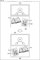
- FIG. 29 shows an example of the situation on the display unit 23B and the desk-type screen 24B on the side of the user B who is the customer.
- the document image is displayed so as not to overlap the object 45. 41B is displayed.
- the pointing image 42 is used for the right hand and the left hand according to the display position of the document image 41B for the user A displayed on the display unit 23B.
- the right hand pointing image 42 and the left hand pointing image 42 are displayed according to which of the left and right sides the document image 41B is displayed with reference to the body axis position of the user A displayed on the display unit 23B. Either one of the pointing images 42 is displayed.
- FIG. 30 shows a flowchart illustrating the seventh communication process.
- step S111 the information processing unit 72B in the communication processing unit 25B adjusts the display of the document image 41B in the document image 41B. Detect the pointing coordinates of.
- step S112 the information processing unit 72B performs image recognition on the image displayed on the display unit 23 according to the display control by the display control unit 73B, and acquires the body axis position of the user A shown in the image. ..
- step S113 the information processing unit 72B determines whether the display position of the document image 41B with respect to the body axis position of the user A acquired in step S112 is the right hand side or the left hand side when viewed from the display unit 23B side. ..
- step S113 when the information processing unit 72B determines that the display position of the document image 41B with respect to the body axis position of the user A is on the right hand side, the process proceeds to step S114.
- step S114 the display control unit 73B controls the projector main body 31B so as to display the pointing image 42 of the right hand according to the pointing coordinates detected in step S111.
- the projector main body 31B displays the pointing image 42 of the right hand on the desk type screen 24B so as to point to the pointing coordinates in the document image 41B, and then the process ends.
- step S113 when the information processing unit 72B determines that the display position of the document image 41B with respect to the body axis position of the user A is on the left hand side, the process proceeds to step S115.
- step S115 the display control unit 73B controls the projector body 31B to display the pointing image 42 of the left hand according to the pointing coordinates detected in step S111.
- the projector main body 31B displays the left-hand pointing image 42 on the desk-type screen 24B so as to point to the pointing coordinates in the document image 41B, and then the process ends.
- the display of the pointing image 42 of the right hand and the pointing image 42 of the left hand is switched according to the arrangement of the document image 41B, which causes a feeling of discomfort in the pointing by the user A. Can be avoided.
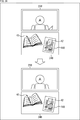
- FIG. 31 shows an example of the situation on the display unit 23B and the desk type screen 24B on the side of the user B who is the customer.
- the pointing image 42 according to the display position of the document image 41B for the user A displayed on the display unit 23B. Can be used with the right hand and the left hand.
- the display position of the document image 41B is the left side of the user A.
- the pointing image 42 of the left hand is displayed on the desk-type screen 24B.
- the left-hand pointing image 42 is displayed on the desk-type screen 24B even though the left hand of the user A is displayed on the display unit 23B. Therefore, in this case, by performing display control such that the left hand of the user A is masked, when the pointing image 42 of the left hand is displayed on the desk-type screen 24B as shown in the lower side of FIG. 31, The user's left hand can be hidden on the display unit 23B.
- the pointing image 42 of the hand on the same side as the hand of the user A displayed on the display unit 23B is displayed on the desk screen 24B, the hand of the user A is displayed. Is avoided.
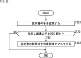
- FIG. 32 shows a flowchart explaining the eighth communication process.
- step S121 the information processing unit 72B displays an image for the image displayed on the display unit 23 according to the display control of the display control unit 73B.
- the recognition By performing the recognition, the hand of the user A shown in the image is recognized.
- step S122 the information processing unit 72B determines whether the hand of the user A recognized in step S121 is on the same side as the hand of the pointing image 42 displayed on the desk-type screen 24B. For example, if the hand of the user A recognized in step S121 is the right hand and the pointing image 42 of the right hand is displayed in step S114 of FIG. 30, the information processing unit 72B determines that those hands are on the same side. judge. On the other hand, when the hand of the user A recognized in step S121 is the right hand and the left-hand pointing image 42 is displayed in step S115 of FIG. 30, the information processing unit 72B determines that those hands are not on the same side. To do. The same determination can be performed when the user A's hand recognized in step S121 is the left hand.
- step S122 when the information processing unit 72B determines that the hand of the user A recognized in step S121 is on the same side as the hand of the pointing image 42, the process proceeds to step S123.
- step S123 the display control unit 73B controls the display unit 23B so as to mask the arm part of the user A shown in the image with the background image. In response to this, the display unit 23B masks the arm part of the user A shown in the image with the background image and hides the arm part of the user A.
- step S123 After the process of step S123, or when the information processing unit 72B determines in step S122 that the hand of the user A recognized in step S121 is not on the same side as the hand of the pointing image 42, the process ends.
- the hand of the user A displayed on the display unit 23B and the hand of the pointing image 42 are on the same side, the hand of the user A is not displayed. Thus, it is possible to avoid a sense of discomfort caused by competing hands on the same side.
- the remote communication system 11 can provide a better user experience to both the user A who is the explainer and the user B who is the customer by performing the above-described first to eighth communication processes. ..
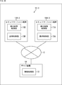
- FIG. 33 is a block diagram showing a configuration example of a second embodiment of a remote communication system to which the present technology is applied.
- the same components as those of the remote communication system 11 of FIG. 1 are designated by the same reference numerals, and detailed description thereof will be omitted.
- the remote communication system 11-2 is connected to the communication terminals 13A and 13B-2 via the network 12, similarly to the remote communication system 11 of FIG.
- the remote communication system 11-2 is different from the remote communication system 11 in FIG. 1 in that the communication terminal 13B-2 has the biosensor 26.
- the biometric sensor 26 is composed of, for example, a heart rate monitor, senses the heartbeat of the user B, and supplies the sensing signal to the communication processing unit 25B. Then, in the communication processing unit 25B, the detection result acquisition unit 71B (see FIG. 2) detects the biometric information of the user B based on the sensing signal supplied from the biometric sensor 26.
- biometric information in addition to the heartbeat of the user B, for example, the amount of sweat of the user B, the line of sight of the user B, the brain wave of the user B, the complexion of the user B, and the like may be used.
- the remote communication system 11-2 based on the biometric information of the user B, for example, the display of the image of the user A displayed on the side of the user B can be adjusted.
- FIG. 34 the process performed by the communication terminal 13A is shown below the broken line, and the process performed by the communication terminal 13B is shown above the broken line.
- a biometric sensing process of acquiring biometric information of the user B is performed based on a sensing signal obtained as a result of the biometric sensor 26 sensing the user B.
- the detection result acquisition unit 71B acquires biometric information such as the pulse rate and sweat state of the user B as a detection result, and the biometric information of the user B is transferred to the communication terminal 13A via the communication unit 55B. Sent.
- a user recognition process is performed on the captured image captured by the camera 21B.
- the information processing unit 72B recognizes the user B captured in the captured image, acquires the display position where the user B is displayed in the captured image, and transmits the display position via the communication unit 55B.
- the display position of the user B is transmitted to the communication terminal 13A.
- the information processing unit 72A subtracts the background image previously acquired and stored in the storage unit 54A from the captured image captured by the camera 21A, so that the user A and the user C are captured.
- the obtained area is acquired as a foreground image.
- the information processing unit 72A recognizes each user and performs a user separation process that separates the user from the foreground image to obtain a user image in which the user A is captured and a user image in which the user C is captured. To do.
- the information processing unit 72A performs user recognition processing on the captured image captured by the camera 21A.
- the storage unit 54A stores a database in which face information of users participating in remote communication is registered, and when the user A is registered as an explainer, the information processing unit 72A is based on the database. By performing the matching, the user recognition result in which the user A shown in the captured image is the explainer is acquired. At this time, the information processing unit 72A acquires a user recognition result in which the user C whose face information is not registered in the database is an onlooker.
- the information processing unit 72A recognizes the contexts of a plurality of communicating users based on the biometric information and the position information of the user B transmitted from the communication terminal 13B and the user recognition result by the user recognition processing. Then, the context recognition relationship specifying process for specifying the relationship between the users is performed.
- the psychological state of the user B is analyzed based on the biometric information of the user B, and it is determined whether the user B is nervous. Further, in the context recognition relationship specifying process, the relationship that the user A is the explainer and the user B is the customer is specified based on the user recognition result, and the user C is the bystander. It is set not to display the user C on the user B side. Then, in the context recognition relationship identifying process, the position parameter X for adjusting the display position of the user A displayed on the user B side is obtained based on the relationship based on the user recognition result and the display position of the user B. ..
- the information processing unit 72A performs display position adjustment processing for adjusting the display position of the user A displayed on the user B side.
- display position adjusting process as will be described later with reference to FIGS. 36 and 37, an arbitrary background image read from the storage unit 54A is displayed so that the user image of the user A has a display position according to the position parameter X.
- the user image of the user A is superimposed.
- the display position adjustment processing as will be described later with reference to FIG. 38, the display size when displaying the user image of the user A can be adjusted.
- the background image used to separate the foreground image may be used as the background image.
- the user image of the user C who is an onlooker is not used. Then, the image generated (reconstructed) by combining the user image of the user A with the background image by the display position adjustment processing is transmitted to the communication terminal 13B as the transmission image via the communication unit 55A.
- the display position of the user image of the user A is adjusted by increasing or decreasing the position parameter X. For example, when the position parameter X is 0.5, the user image of the user A is superimposed on the center of the transmission image in the X-axis direction. Similarly, when the position parameter X is 0.3, the user image of the user A is superimposed on the left side of the transmission image, and when the position parameter X is 0.7, the user image of the user A is superimposed on the right side of the transmission image.
- the sales person (user A) talks to the customer (user B) who first meets using the remote communication system 11-2
- the sales person when the customer sees the sales person displayed on the display unit 23B, the sales person There is a psychology that I do not want to feel the intimidation of (I do not want the sales staff to feel likewise).
- the salesperson looks at the customer displayed on the display unit 23B, there is a need to observe the customer's facial expression from the front and read the changes in the customer's interest and purchasing motivation.
- the initial value of the position parameter X for displaying the sales person is set to 0.7, and the initial value of the position parameter X for displaying the customer is set to 0.5.
- the psychological intimidation to the customer is the highest, and the intimidation feeling is reduced by the amount of shifting the sales person from the center.
- the position parameter X is set to be displaced to the left side (that is, the left side of C in FIG. 35). By doing so, the display control is performed so that the gaze becomes stronger.
- the position parameter X so as to shift it to the right (that is, the right side of C in FIG. 35)
- the display control is performed so that the intimidating feeling is not bothered.
- the doctor (user A) asks the patient (user B) whom he/she first met by using the remote communication system 11-2
- the display control for displaying the doctor is performed. As a result, when the patient's tension becomes low, display control is performed to display the doctor so that the doctor gradually shifts to the left toward the center.
- the initial value of the scale parameter S representing the display size of the user image is set to 100% and the tension of the customer or the patient is high like the display position of the user image, For example, display control is performed such that the user image is reduced to 80%. This can provide a psychological effect of reducing the intimidation of the sales person or the doctor.
- the display position or the display size can be adjusted according to the biometric information. For example, by reducing the tension without giving an intimidating feeling, better remote communication can be achieved. Can be planned.
- the remote communication system 11-2 does not transmit the raw data of the biometric information in order to reduce the communication load, but only when the psychological state of the user recognized from the biometric information changes. You may make it transmit the information which shows a change. For example, as the user's psychological state recognized from biometric information, "tension”, “interest”, “stress”, or “drowsiness” is used. And information indicating those changes is transmitted.
- FIG. 36 shows a flowchart for explaining the first processing example of the ninth communication processing.
- step S132 in the communication processing unit 25B, the detection result acquisition unit 71B performs the biometric sensing process, so that, for example, the heartbeat data of the user B sensed by the biometric sensor 26 is read and acquired as the detection result. Then, the communication unit 55B transmits the transmission detection result to the communication terminal 13A.
- step S133 the information processing unit 72A analyzes the psychological state based on the heartbeat data of the user B transmitted in step S132, and determines whether the tension state of the user B is high or low.
- step S133 the information processing unit 72A determines whether or not the position parameter X at the present time is equal to or less than a first position parameter threshold value (for example, 0.8) preset as an upper limit value.
- a first position parameter threshold value for example, 0.8
- step S134 when the information processing unit 72A determines that the position parameter X at the present time is equal to or smaller than the first position parameter threshold value, the process proceeds to step S135.
- step S134 when the information processing unit 72A determines that the current position parameter X is not less than or equal to the first position parameter threshold value, the process skips step S135 and proceeds to step S138. That is, in this case, since the position parameter X at the present time point has already become the first position parameter threshold value, further increase of the position parameter X is not performed.
- step S133 when the information processing unit 72A determines that the tension state of the user B is low, the process proceeds to step S136.
- step S136 the information processing unit 72A determines whether or not the position parameter X at the current time point is larger than a second position parameter threshold value (for example, 0.5) preset as a lower limit value.
- a second position parameter threshold value for example, 0.5
- step S136 when the information processing unit 72A determines that the current position parameter X is larger than the second position parameter threshold value, the process proceeds to step S137.
- step S136 when the information processing unit 72A determines that the current position parameter X is not less than or equal to the second position parameter threshold value, the process skips step S137 and proceeds to step S138. That is, in this case, since the position parameter X at the present time point has already become the second position parameter threshold value, further decrease of the position parameter X is not performed.
- step S138 the information processing unit 72A adjusts the display position of the user image in which the user A is imaged, using the position parameter X as the coordinate X in the X direction of the user image in which the user A is imaged. Then, the information processing unit 72A generates the transmission image by superimposing the user image showing the user A as the foreground of the background image at the adjusted display position. Then, the communication unit 55A transmits the transmission image to the communication terminal 13B, and the transmission image is displayed on the display unit 23B.
- step S139 the information processing unit 72A determines whether or not to end the display of the image on the communication terminal 13B side, and if it is determined that the display is not to be ended, the process returns to step S132, and so on. The process is repeated.
- step S139 the process ends.
- the first processing example of the ninth communication processing is applied to the use case in which the sales clerk (user A) talks to the customer (user B) as described above. Good remote communication can be achieved without intimidating the customer.
- the initial display position of the user A may be set according to the position of the user A captured in the captured image captured by the camera 21A.
- FIG. 37 shows a flowchart for explaining the second processing example of the ninth communication processing.
- step S141 in the communication processing unit 25A, the information processing unit 72A recognizes the position of the user A captured in the captured image captured by the camera 21A, and sets the user position X1 as the reference display position of the user A. Set.
- steps S143 and S144 the same processing as steps S132 and S133 in FIG. 36 is performed, and when the information processing unit 72A determines in step S144 that the tension of the user B is high, the processing proceeds to step S145.
- step S145 the information processing unit 72A determines whether or not the position adjustment amount ⁇ at the present time is equal to or smaller than a first position adjustment amount threshold value (for example, 0.4) preset as an upper limit value.
- a first position adjustment amount threshold value for example, 0.4
- step S145 when the information processing unit 72A determines that the current position adjustment amount ⁇ is equal to or smaller than the first position adjustment amount threshold value, the process proceeds to step S146.
- step S145 when the information processing unit 72A determines that the current position adjustment amount ⁇ is not less than or equal to the first position adjustment amount threshold value, the process skips step S146 and proceeds to step S149. That is, in this case, since the position adjustment amount ⁇ at this point is the first position adjustment amount threshold value, the position adjustment amount ⁇ is not further increased.
- step S144 when the information processing unit 72A determines that the tension state of the user B is low, the process proceeds to step S147.
- step S147 the information processing unit 72A determines whether or not the position adjustment amount ⁇ at the current time point is larger than a second position adjustment amount threshold value (for example, 0) preset as a lower limit value.
- a second position adjustment amount threshold value for example, 0
- step S147 when the information processing unit 72A determines that the position adjustment amount ⁇ at the current time point is larger than the second position adjustment amount threshold value, the process proceeds to step S148.
- step S147 when the information processing unit 72A determines in step S147 that the current position adjustment amount ⁇ is not less than or equal to the second position adjustment amount threshold value, the process skips step S148 and proceeds to step S149. That is, in this case, since the position adjustment amount ⁇ at this time point is the second position adjustment amount threshold value, the position adjustment amount ⁇ is not further reduced.
- step S149 the information processing section 72A adjusts the coordinate X in the X direction of the user image in which the user A is photographed (X1+ ⁇ ) according to the position adjustment amount ⁇ , with the user position X1 as the reference display position of the user A.
- the user image showing the user A is superimposed as the foreground of the background image to generate a transmission image.
- the communication unit 55A transmits the transmission image to the communication terminal 13B, and the transmission image is displayed on the display unit 23B.
- step S150 the information processing unit 72A determines whether or not to end the display of the image on the communication terminal 13B side, and if it is determined not to end the display, the process returns to step S143, and so on. The process is repeated.
- step S150 the process is ended.
- the doctor can Good remote communication can be achieved without intimidating the user.
- FIG. 38 shows a flowchart illustrating the tenth communication process.
- step S163 the same processing as steps S132 and S133 in FIG. 36 is performed, and in step S163, when the information processing unit 72A determines that the tension state of the user B is high, the processing proceeds to step S164.
- step S164 the information processing unit 72A determines whether or not the scale parameter S at the present time point is larger than a first scale parameter threshold value (for example, 80%) preset as a lower limit value.
- a first scale parameter threshold value for example, 80%
- step S165 when the information processing unit 72A determines that the scale parameter S at the current time point is larger than the first scale parameter threshold value, the process proceeds to step S165.
- step S164 when the information processing unit 72A determines in step S164 that the scale parameter S at the present time is not larger than the first scale parameter threshold value, the process skips step S165 and proceeds to step S168. That is, in this case, since the scale parameter S at this point is the first scale parameter threshold value, the scale parameter S is not further reduced.
- step S163 when the information processing unit 72A determines that the tension of the user B is low, the process proceeds to step S166.
- step S166 the information processing unit 72A determines whether or not the scale parameter S at the present time is equal to or less than a second scale parameter threshold value (for example, 100%) preset as an upper limit value.
- a second scale parameter threshold value for example, 100%
- step S166 determines in step S166 that the scale parameter S at the present time is equal to or smaller than the second scale parameter threshold value, the process proceeds to step S167.
- step S166 when the information processing unit 72A determines in step S166 that the scale parameter S at the present time is not less than or equal to the second scale parameter threshold value, the process skips step S167 and proceeds to step S168. That is, in this case, since the scale parameter S at this time is the second scale parameter threshold value, the scale parameter S is not further increased.
- step S168 the information processing unit 72A adjusts the display size when the user image in which the user A is displayed is displayed according to the scale parameter S, and the user image in which the user A is displayed is the adjusted display size. Is superimposed as the foreground of the background image to generate a transmission image. Then, the communication unit 55A transmits the transmission image to the communication terminal 13B, and the transmission image is displayed on the display unit 23B.
- step S169 the information processing unit 72A determines whether or not to end the display of the image on the communication terminal 13B side. If it is determined not to end the display, the process returns to step S162, and so on. The process is repeated.
- the tenth communication process is used together with the above-described ninth communication process in a use case in which the sales person (user A) talks to the customer (user B), and the doctor (user A) is the patient (user B). It can be applied to the use case to ask.
- the remote communication system 11-2 can perform remote communication in an environment close to actual face-to-face communication, and can achieve more natural communication. Further, the remote communication system 11-2 provides an intentional environment that cannot be realized by actual face-to-face communication according to the purpose of communication, and for example, recognizes a tense state and does not give an intimidating feeling. Can lead communication.
- FIG. 39 is a block diagram showing a configuration example of a third embodiment of a remote communication system to which the present technology is applied.
- the same components as those of the remote communication system 11 of FIG. 1 are designated by the same reference numerals, and detailed description thereof will be omitted.
- the remote communication system 11-3 is connected to the communication terminals 13A-3 and 13B-3 via the network 12, similarly to the remote communication system 11 of FIG.
- the communication terminal 13A-3 has a detection result acquisition unit 71A and a display control unit 73A
- the communication terminal 13B-3 has a detection result acquisition unit 71B and a display control unit 73B.
- the remote communication system 11-3 is different from the remote communication system 11 in FIG. 1 in that the server device 14 having the information processing unit 72 is connected to the network 12.
- the communication terminals 13A and 13B each have the detection result acquisition unit 71, the information processing unit 72, and the display control unit 73.
- the server device 14 has the information processing unit 72 and communicates with the communication terminals 13A-3 and 13B-3 via the network 12 to perform the information processing as described above.
- Various processing executed by the unit 72 is configured to be performed via the network 12.
- FIG. 40 is a block diagram showing a configuration example of an embodiment of a computer in which a program for executing the series of processes described above is installed.
- the program can be recorded in advance in the hard disk 105 or the ROM 103 as a recording medium built in the computer.
- the program can be stored (recorded) in the removable recording medium 111 driven by the drive 109.
- a removable recording medium 111 can be provided as so-called package software.
- examples of the removable recording medium 111 include a flexible disk, a CD-ROM (Compact Disc Read Only Memory), an MO (Magneto Optical) disc, a DVD (Digital Versatile Disc), a magnetic disc, and a semiconductor memory.
- the program can be installed in the computer from the removable recording medium 111 as described above, or downloaded to the computer via a communication network or a broadcast network and installed in the built-in hard disk 105. That is, for example, the program is wirelessly transferred from a download site to a computer via an artificial satellite for digital satellite broadcasting, or wired to a computer via a network such as a LAN (Local Area Network) or the Internet. be able to.
- LAN Local Area Network
- the computer contains a CPU (Central Processing Unit) 102, and an input/output interface 110 is connected to the CPU 102 via a bus 101.
- CPU Central Processing Unit
- the CPU 102 executes a program stored in a ROM (Read Only Memory) 103 in response to a command input by the user operating the input unit 107 via the input/output interface 110. .. Alternatively, the CPU 102 loads a program stored in the hard disk 105 into a RAM (Random Access Memory) 104 and executes the program.
- ROM Read Only Memory
- RAM Random Access Memory
- the CPU 102 performs the processing according to the above-described flowchart or the processing performed by the configuration of the above-described block diagram. Then, the CPU 102 outputs the processing result, for example, from the output unit 106 via the input/output interface 110, or transmitted from the communication unit 108, and further recorded on the hard disk 105, as necessary.
- the input unit 107 is composed of a keyboard, a mouse, a microphone, and the like.
- the output unit 106 includes an LCD (Liquid Crystal Display), a speaker, and the like.
- the processing performed by the computer according to the program does not necessarily have to be performed in time series in the order described as the flowchart. That is, the processing performed by the computer according to the program also includes processing that is executed in parallel or individually (for example, parallel processing or object processing).
- the program may be processed by one computer (processor) or may be processed by a plurality of computers in a distributed manner. Further, the program may be transferred to a remote computer and executed.
- the system means a set of a plurality of constituent elements (devices, modules (parts), etc.), and it does not matter whether or not all constituent elements are in the same housing. Therefore, a plurality of devices housed in separate housings and connected via a network, and one device housing a plurality of modules in one housing are all systems. ..
- the configuration described as one device (or processing unit) may be divided and configured as a plurality of devices (or processing units).
- the configurations described above as a plurality of devices (or processing units) may be integrated into one device (or processing unit).
- part of the configuration of a certain device (or processing unit) may be included in the configuration of another device (or other processing unit). ..
- the present technology may have a configuration of cloud computing in which a single function is shared by a plurality of devices via a network and jointly processes.
- the above-mentioned program can be executed in any device.
- the device may have a necessary function (function block or the like) so that necessary information can be obtained.
- each step described in the above-described flowchart can be executed by one device or shared by a plurality of devices.
- the plurality of processes included in the one step can be executed by one device or shared by a plurality of devices.
- a plurality of processes included in one step can be executed as a process of a plurality of steps.
- the processes described as a plurality of steps can be collectively executed as one step.
- the program executed by the computer may be configured such that the processes of the steps for writing the program are executed in time series in the order described in this specification, or in parallel or when the calls are made. It may be executed individually at a necessary timing such as time. That is, as long as no contradiction occurs, the processing of each step may be executed in an order different from the order described above. Furthermore, the process of the step of writing this program may be executed in parallel with the process of another program, or may be executed in combination with the process of another program.
- the present technology may also be configured as below.
- an information processing unit that performs information processing to make the presentation content presented on the user side different from the other user side.
- a detection result acquisition unit that acquires the detection result,
- the information processing apparatus according to (1) further including: a display control unit configured to perform display control for displaying an image serving as the presentation content in accordance with information processing performed by the information processing unit.
- the detection result acquisition unit acquires one of the user's hand movements as the detection result, When the information processing unit recognizes that one of the users has made a pointing gesture to instruct a predetermined instruction point, based on the detection result, acquires the instruction point,
- the information processing apparatus according to (2) wherein the display control unit performs display control to cause the other user side to display a pointing image that points to the instruction point.
- a shared area for sharing the display of the image with the other user side is set, The information processing device according to (3), wherein the information processing unit causes the display control unit to perform display control of the pointing image when the instruction point is within the shared area.
- the sharing area is set so as to surround a document image shared with the other user side inside
- the information processing unit when recognizing that one of the users has performed a tap gesture of tapping a predetermined item of the document image, acquires related information related to the item,
- the display control unit performs a display control of displaying the related information image representing the related information on the other user side,
- the information processing unit according to (4), wherein the information processing unit updates the shared area so as to surround the document image and the related information image.
- the shared area is set on one of the user sides so as to surround at least one shared object shared with the other user side, When the information processing unit recognizes that one of the users has changed the number of shared objects based on the detection result, the information processing unit updates the shared area so as to surround one or more shared objects.
- the information processing device according to (4) above.
- a private area that is not shared with the other user side is set between the first document image and the second document image, and one of the users points to the pointing area. When it is recognized that the fingertip is moved from the first document image to the second document image without changing the gesture, display control for hiding the pointing image while the fingertip is in the private area is performed.
- the information processing apparatus according to (5) above.
- a private area that is not shared with the other user side is set between the first document image and the second document image, and one of the users points to the pointing area. If it is recognized that the fingertip is moved from the first document image to the second document image as a gesture, it is recognized last in the first document image while the fingertip is in the private area.
- display control is performed to stop updating the display of the pointing image at the instruction point.
- the display control unit On the one user side, display control is performed to display the document image with the back side viewed downward from one of the users, On the other user side, the document image is displayed with the front side facing downward from the other user, and the hand of the pointing image is on the back side as viewed from the other user.
- the information processing apparatus according to (5), which performs display control for displaying.
- the display control unit On the one user side, display control is performed to display the document image with the front side viewed downward from one of the users, On the other user side, the document image is displayed with the front side facing downward from the other user, and the hand of the pointing image is on the back side as viewed from the other user.
- the information processing apparatus according to (5) which performs display control for displaying.
- the display control unit On the one user side, display control is performed to display the document image with the front side viewed downward from one of the users, On the other user side, the document image is displayed with the front side facing downward from the other user, and the hand of the pointing image is on the front side viewed from the other user.
- the information processing apparatus according to (5) which performs display control for displaying.
- the detection result acquisition unit acquires an object placed in a display area for displaying the image on the other user side as the detection result,
- the information processing apparatus according to any one of (3) to (11), wherein the display control unit displays the image so as to fit in an empty space other than an area where the object is placed.
- the display control unit when the image is displayed in the empty space, with the body axis position in the image of one user displayed on the other user side as a reference, the pointing image of the right hand and the pointing image of the left hand.
- the information processing device which performs display control for switching display with a pointing image.
- the display control unit When the right hand is shown in the image of one of the users when the pointing image of the right hand is displayed, the right hand in the image of the user is hidden, The left hand in the image of the user is hidden when the left hand is shown in the image of the one user while the pointing image of the left hand is displayed. apparatus.
- the detection result acquisition unit acquires the biometric information of the other user as the detection result, The information processing unit adjusts a display position or a display size of one of the users in an image of the one user displayed on the side of the other user based on the biometric information.
- Information processing device (16) The information processing unit recognizes a relationship between the one user and the other user, and adjusts a display position or a display size of the one user based on the relationship. (15) Information processing device.
- the An information processing method comprising: performing information processing in which the presentation content presented on the user side is different from that on the other user side.
- At least two users communicate with a terminal used for communication while viewing each other's images transmitted and received via a network, and based on the detection result obtained as a result of sensing one of the users.
- the information processing apparatus includes an information processing unit that performs information processing to make the presentation content presented by one of the users different from that of the other user.
- 11 remote communication system 12 network, 13 communication terminal, 14 server device, 21 camera, 22 projector unit, 23 display unit, 24 desk type screen, 25 communication processing unit, 26 biosensor, 31 projector body, 32 stereo camera, 33 RGB camera, 41 document image, 42 pointing image, 43 related information image, 44 shared object, 45 object, 51 input section, 52 output section, 53 operation input section, 54 storage section, 55 communication section, 56 control section, 61 Transmission unit, 62 reception unit, 71 detection result acquisition unit, 72 information processing unit, 73 display control unit
Landscapes
- Engineering & Computer Science (AREA)
- Theoretical Computer Science (AREA)
- General Engineering & Computer Science (AREA)
- Human Computer Interaction (AREA)
- Physics & Mathematics (AREA)
- General Physics & Mathematics (AREA)
- Multimedia (AREA)
- Signal Processing (AREA)
- User Interface Of Digital Computer (AREA)
- Information Transfer Between Computers (AREA)
- Two-Way Televisions, Distribution Of Moving Picture Or The Like (AREA)
Abstract
La présente invention concerne un dispositif de traitement d'informations et un procédé de traitement d'informations qui permettent de fournir une meilleure expérience utilisateur. La présente invention comprend : une unité d'obtention de résultat de détection qui, lorsqu'une communication est effectuée par au moins deux utilisateurs tout en visualisant une image de chaque autre utilisateur envoyée et reçue par l'intermédiaire d'un réseau, obtient un résultat de détection obtenu suite à la détection d'un des utilisateurs ; une unité de traitement d'informations qui effectue, sur la base du résultat de détection, un traitement d'informations dans lequel un contenu de présentation à présenter du côté d'un utilisateur est rendu différent de celui du côté de l'autre utilisateur ; et une unité de commande d'affichage qui effectue une commande d'affichage de façon à amener une image, qui sert de contenu de présentation, à s'afficher conformément au traitement d'informations. La présente technologie peut être appliquée, par exemple, à un système de communication à distance.
Priority Applications (4)
| Application Number | Priority Date | Filing Date | Title |
|---|---|---|---|
| EP20752363.0A EP3923149A4 (fr) | 2019-02-04 | 2020-01-21 | Dispositif de traitement d'informations et procédé de traitement d'informations |
| CN202080011344.6A CN113366455A (zh) | 2019-02-04 | 2020-01-21 | 信息处理装置和信息处理方法 |
| US17/422,611 US20220091809A1 (en) | 2019-02-04 | 2020-01-21 | Information processing device and information processing method |
| JP2020571074A JPWO2020162154A1 (ja) | 2019-02-04 | 2020-01-21 | 情報処理装置および情報処理方法 |
Applications Claiming Priority (2)
| Application Number | Priority Date | Filing Date | Title |
|---|---|---|---|
| JP2019017646 | 2019-02-04 | ||
| JP2019-017646 | 2019-02-04 |
Publications (1)
| Publication Number | Publication Date |
|---|---|
| WO2020162154A1 true WO2020162154A1 (fr) | 2020-08-13 |
Family
ID=71947418
Family Applications (1)
| Application Number | Title | Priority Date | Filing Date |
|---|---|---|---|
| PCT/JP2020/001795 Ceased WO2020162154A1 (fr) | 2019-02-04 | 2020-01-21 | Dispositif de traitement d'informations et procédé de traitement d'informations |
Country Status (5)
| Country | Link |
|---|---|
| US (1) | US20220091809A1 (fr) |
| EP (1) | EP3923149A4 (fr) |
| JP (1) | JPWO2020162154A1 (fr) |
| CN (1) | CN113366455A (fr) |
| WO (1) | WO2020162154A1 (fr) |
Families Citing this family (4)
| Publication number | Priority date | Publication date | Assignee | Title |
|---|---|---|---|---|
| WO2021229650A1 (fr) * | 2020-05-11 | 2021-11-18 | ソニーグループ株式会社 | Dispositif de communication, procédé et programme |
| US12198292B2 (en) * | 2020-12-23 | 2025-01-14 | Intel Corporation | Writing/drawing-to-digital asset extractor |
| JP2023007696A (ja) * | 2021-07-02 | 2023-01-19 | セイコーエプソン株式会社 | 画像処理方法および画像処理装置 |
| WO2024083302A1 (fr) * | 2022-10-17 | 2024-04-25 | Telefonaktiebolaget Lm Ericsson (Publ) | Portail virtuel entre un espace physique et un espace virtuel dans des environnements de réalité étendue |
Citations (7)
| Publication number | Priority date | Publication date | Assignee | Title |
|---|---|---|---|---|
| JPH09163336A (ja) * | 1995-12-08 | 1997-06-20 | Ricoh Co Ltd | テレビ会議システム |
| JPH09237154A (ja) * | 1996-03-04 | 1997-09-09 | Canon Inc | テレビ会議装置 |
| JP2003284017A (ja) * | 2002-03-26 | 2003-10-03 | Sumitomo Electric Ind Ltd | 端末装置、双方向対話型システム、ヘッドセット及びマルチウィンドウ表示方法 |
| JP2011030244A (ja) | 2010-09-13 | 2011-02-10 | Sony Corp | 画像処理装置、画像処理方法、プログラム |
| JP2013070368A (ja) * | 2011-09-05 | 2013-04-18 | Panasonic Corp | テレビ対話システム、端末および方法 |
| JP2014230282A (ja) * | 2013-05-22 | 2014-12-08 | ソニー株式会社 | 等身大イメージを用いるテレビ会議のための携帯型透明ディスプレイ |
| JP2018073093A (ja) * | 2016-10-28 | 2018-05-10 | キヤノン株式会社 | 表示制御システム、画像処理装置、表示制御方法、及びプログラム |
Family Cites Families (5)
| Publication number | Priority date | Publication date | Assignee | Title |
|---|---|---|---|---|
| US5107443A (en) * | 1988-09-07 | 1992-04-21 | Xerox Corporation | Private regions within a shared workspace |
| JP5957893B2 (ja) * | 2012-01-13 | 2016-07-27 | ソニー株式会社 | 情報処理装置及び情報処理方法、並びにコンピューター・プログラム |
| US9491418B2 (en) * | 2012-11-15 | 2016-11-08 | Steen Svendstorp Iversen | Method of providing a digitally represented visual instruction from a specialist to a user in need of said visual instruction, and a system therefor |
| US10645137B2 (en) * | 2015-12-28 | 2020-05-05 | Facebook, Inc. | Systems and methods to create composite videos |
| JP7342857B2 (ja) * | 2018-03-28 | 2023-09-12 | ソニーグループ株式会社 | 情報処理装置、情報処理方法、およびプログラム |
-
2020
- 2020-01-21 JP JP2020571074A patent/JPWO2020162154A1/ja not_active Abandoned
- 2020-01-21 WO PCT/JP2020/001795 patent/WO2020162154A1/fr not_active Ceased
- 2020-01-21 EP EP20752363.0A patent/EP3923149A4/fr not_active Withdrawn
- 2020-01-21 US US17/422,611 patent/US20220091809A1/en not_active Abandoned
- 2020-01-21 CN CN202080011344.6A patent/CN113366455A/zh not_active Withdrawn
Patent Citations (7)
| Publication number | Priority date | Publication date | Assignee | Title |
|---|---|---|---|---|
| JPH09163336A (ja) * | 1995-12-08 | 1997-06-20 | Ricoh Co Ltd | テレビ会議システム |
| JPH09237154A (ja) * | 1996-03-04 | 1997-09-09 | Canon Inc | テレビ会議装置 |
| JP2003284017A (ja) * | 2002-03-26 | 2003-10-03 | Sumitomo Electric Ind Ltd | 端末装置、双方向対話型システム、ヘッドセット及びマルチウィンドウ表示方法 |
| JP2011030244A (ja) | 2010-09-13 | 2011-02-10 | Sony Corp | 画像処理装置、画像処理方法、プログラム |
| JP2013070368A (ja) * | 2011-09-05 | 2013-04-18 | Panasonic Corp | テレビ対話システム、端末および方法 |
| JP2014230282A (ja) * | 2013-05-22 | 2014-12-08 | ソニー株式会社 | 等身大イメージを用いるテレビ会議のための携帯型透明ディスプレイ |
| JP2018073093A (ja) * | 2016-10-28 | 2018-05-10 | キヤノン株式会社 | 表示制御システム、画像処理装置、表示制御方法、及びプログラム |
Non-Patent Citations (1)
| Title |
|---|
| See also references of EP3923149A4 |
Also Published As
| Publication number | Publication date |
|---|---|
| US20220091809A1 (en) | 2022-03-24 |
| CN113366455A (zh) | 2021-09-07 |
| EP3923149A4 (fr) | 2022-04-06 |
| JPWO2020162154A1 (ja) | 2021-12-09 |
| EP3923149A1 (fr) | 2021-12-15 |
Similar Documents
| Publication | Publication Date | Title |
|---|---|---|
| Plopski et al. | The eye in extended reality: A survey on gaze interaction and eye tracking in head-worn extended reality | |
| US12125149B2 (en) | Interfaces for presenting avatars in three-dimensional environments | |
| EP4139777B1 (fr) | Présentation d'avatars dans des environnements tridimensionnels | |
| CN112184356B (zh) | 指导式零售体验 | |
| Carmigniani et al. | Augmented reality technologies, systems and applications | |
| Carmigniani et al. | Augmented reality: an overview | |
| CN117980962A (zh) | 用于内容应用的设备、方法和图形用户界面 | |
| WO2020162154A1 (fr) | Dispositif de traitement d'informations et procédé de traitement d'informations | |
| IL267683A (en) | Automatic control of a display device based on wearable external conditions | |
| US20250022237A1 (en) | Interfaces for presenting avatars in three-dimensional environments | |
| JP7613015B2 (ja) | コンテキスト及びコンテンツを意識した3D手ジェスチャ視覚化を伴うWebベースリモートアシスタンスシステムに関するプログラム | |
| Du et al. | Human–robot collaborative control in a virtual-reality-based telepresence system | |
| US20260045055A1 (en) | Collaborative system | |
| US11366631B2 (en) | Information processing device, information processing method, and program | |
| CN107949821A (zh) | 被注视虚拟对象识别模块、用于实现注视半透明的系统和相关方法 | |
| EP3745237A1 (fr) | Rendu d'une image sur une interface d'utilisateur virtuelle d'un dispositif de réalité augmentée ou virtuelle | |
| CN118012265A (zh) | 人机交互方法、装置、设备和介质 | |
| Vanderheiden | Accessible and Usable Design of Information and Communication Technologies. | |
| US20240221237A1 (en) | Control apparatus | |
| US12166957B2 (en) | Generating and displaying content based on respective positions of individuals | |
| Bektas et al. | Magic Gaze: Enabling Seamless Control of IoT Devices Through Eye Tracking | |
| Bhowmik | Senses, Perception, and Natural Human‐Interfaces for Interactive Displays | |
| Walkowski et al. | Using a game controller for relaying deictic gestures in computer-mediated communication | |
| Jamalzadeh | Eyes-free gestural interaction with smartphone using haptic feedback |
Legal Events
| Date | Code | Title | Description |
|---|---|---|---|
| 121 | Ep: the epo has been informed by wipo that ep was designated in this application |
Ref document number: 20752363 Country of ref document: EP Kind code of ref document: A1 |
|
| ENP | Entry into the national phase |
Ref document number: 2020571074 Country of ref document: JP Kind code of ref document: A |
|
| NENP | Non-entry into the national phase |
Ref country code: DE |
|
| ENP | Entry into the national phase |
Ref document number: 2020752363 Country of ref document: EP Effective date: 20210906 |