WO2020174541A1 - Outil de traitement par ultrasons - Google Patents
Outil de traitement par ultrasons Download PDFInfo
- Publication number
- WO2020174541A1 WO2020174541A1 PCT/JP2019/007094 JP2019007094W WO2020174541A1 WO 2020174541 A1 WO2020174541 A1 WO 2020174541A1 JP 2019007094 W JP2019007094 W JP 2019007094W WO 2020174541 A1 WO2020174541 A1 WO 2020174541A1
- Authority
- WO
- WIPO (PCT)
- Prior art keywords
- opening
- ultrasonic treatment
- piezoelectric element
- ultrasonic
- treatment device
- Prior art date
- Legal status (The legal status is an assumption and is not a legal conclusion. Google has not performed a legal analysis and makes no representation as to the accuracy of the status listed.)
- Ceased
Links
Images




Classifications
-
- A—HUMAN NECESSITIES
- A61—MEDICAL OR VETERINARY SCIENCE; HYGIENE
- A61B—DIAGNOSIS; SURGERY; IDENTIFICATION
- A61B17/00—Surgical instruments, devices or methods
- A61B17/22—Implements for squeezing-off ulcers or the like on inner organs of the body; Implements for scraping-out cavities of body organs, e.g. bones; for invasive removal or destruction of calculus using mechanical vibrations; for removing obstructions in blood vessels, not otherwise provided for
-
- A—HUMAN NECESSITIES
- A61—MEDICAL OR VETERINARY SCIENCE; HYGIENE
- A61N—ELECTROTHERAPY; MAGNETOTHERAPY; RADIATION THERAPY; ULTRASOUND THERAPY
- A61N7/00—Ultrasound therapy
Definitions
- the present invention relates to an ultrasonic treatment tool.
- transurethral lithotripsy which inserts the tip of the treatment tool into the urinary tract and crushes stones, has become the mainstream.
- a treatment tool used for transurethral lithotripsy is required to have high lithotripsy performance, and it is also required that the tip has a small diameter and can be inserted through an endoscope channel. ..
- Patent Document 1 describes an ultrasonic treatment instrument having a thin tip and capable of high output.
- the ultrasonic treatment tool of Patent Document 1 has an ultrasonic transducer formed of a cylindrical piezoelectric element at the tip of the insertion portion, and when the ultrasonic transducer is filled with cooling water, Ultrasound is emitted toward the affected area.
- the ultrasonic transducer formed of a cylindrical piezoelectric element has a small diameter and is easily inserted into the body cavity.
- an object of the present invention is to provide an ultrasonic treatment tool having a small diameter and high output.
- An ultrasonic treatment instrument is an ultrasonic treatment instrument that propagates an ultrasonic wave in a body and treats it, and has a cavity in which a first opening at a distal end and a second opening at a proximal end are opened.
- a piezoelectric element having a cylindrical shape having a polarization direction in a thickness direction connecting an inner peripheral surface and an outer peripheral surface, and a piezoelectric element connected to the base end of the piezoelectric element and provided from a third opening provided at the tip to the base end. And a long portion in which the third opening communicates with the second opening and the fourth opening is disposed outside the body, and the third opening communicates with the second opening.
- a through hole that penetrates to the fourth opening is formed.
- the ultrasonic treatment tool according to the first aspect may include a suction device that is connected to the fourth opening and that sucks the air inside the through hole.
- the ultrasonic treatment tool according to the first aspect may include a water supply device that is connected to the fourth opening and supplies water into the through hole.
- the distal end side is arranged over a region from the first opening of the through hole to a predetermined position of the through hole. It may have a hydrophilic treatment region and a water repellent treatment region arranged on the base end side, and the hydrophilic treatment region may be more hydrophilic than the water repellent treatment region.
- the hydrophilic treatment region and the water repellent treatment region are the inner peripheral surface of a thin film tube provided inside the through hole. May be formed in.
- the distance from the first opening to the boundary between the hydrophilic treatment region and the water repellent treatment region is
- the columnar liquid formed from the first opening to the boundary may have a length at which the resonance frequency in the radial direction is equal to the resonance frequency in the radial direction of the piezoelectric element.
- the through hole may have a reflecting surface that is substantially perpendicular to the longitudinal direction of the piezoelectric element.
- the distance from the first opening to the reflecting surface is a circle formed from the first opening to the reflecting surface.
- the columnar liquid may have a length such that the radial resonance frequency is equal to the radial resonance frequency of the piezoelectric element.
- the ultrasonic treatment tool has a plug that seals the first opening, and a cord that can pull the plug from the proximal end side. Good.
- the stopper when the plug is pulled toward the proximal end side, the stopper is engaged with the stopper to move the stopper toward the proximal end. You may have the convex part which limits.
- the distance from the first opening to the tip of the plug is
- the resonance frequency in the radial direction of the cylindrical liquid formed from the first opening to the tip of the plug may be equal to the resonance frequency in the radial direction of the piezoelectric element.
- An endoscope treatment system is an endoscope having an ultrasonic treatment instrument according to any one of the first to eleventh aspects and a channel into which the ultrasonic treatment instrument can be inserted. And a mirror.
- the ultrasonic treatment instrument of the present invention it is possible to provide an ultrasonic treatment instrument having a small diameter and high output.
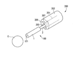
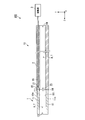
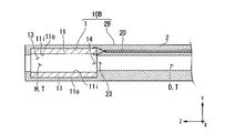
- FIG. 1 shows the whole structure of the calculus crushing system provided with the ultrasonic treatment tool which concerns on 1st embodiment of this invention. It is a perspective view of the tip of the endoscope insertion part which opposes the calculus of a crushing object. It is a block diagram of the ultrasonic oscillating part of the ultrasonic treatment instrument. It is a sectional view of the ultrasonic oscillating part in which the cavity was filled with liquid. It is sectional drawing of the modification of the insertion part of the ultrasonic treatment instrument. It is sectional drawing of the modification of the insertion part of the ultrasonic treatment instrument. It is a block diagram of the ultrasonic treatment instrument which concerns on 2nd embodiment of this invention.
- FIG. 1 is a diagram showing an overall configuration of a calculus crushing system 300.
- the calculus breaking system (endoscopic treatment system) 300 includes an endoscope 200 inserted into the urethra U and an ultrasonic treatment instrument 100 inserted into a channel of the endoscope 200. I have it.
- the endoscope 200 is appropriately selected from known flexible ureteroscopes including a long endoscope insertion portion 202 having a treatment instrument channel 201 through which a treatment instrument can be inserted.
- the endoscope 200 has an operation unit 204 at the base end.
- the operation section 204 is provided with a treatment instrument insertion hole 205, and the ultrasonic treatment instrument 100 is inserted into the treatment instrument channel 201 through the treatment instrument insertion hole 205.
- FIG. 2 is a perspective view of the tip of the endoscope insertion portion 202 facing the calculus C to be crushed.
- the endoscope 200 has an illumination 206 and an imaging unit 207 at the tip of the endoscope insertion unit 202.
- the tip of the ultrasonic treatment instrument 100 inserted into the treatment instrument channel 201 projects from the treatment instrument channel opening 203 at the tip of the endoscope insertion portion 202.
- the endoscope 200 sends water into the body by discharging the water conveyed via the treatment instrument channel 201 from the treatment instrument channel opening 203.
- the water discharged from the treatment tool channel opening 203 is perfused through a separately provided drainage channel or the like.
- the water supply channel and the water supply channel opening are provided in the endoscope 200, and the water conveyed through the water supply channel is discharged into the body by being discharged from the water supply channel opening at the tip of the endoscope 200. Also good.
- the water discharged from the water supply channel opening is perfused through the treatment tool channel 201, a separately provided drainage channel, and the like.
- the endoscope 200 is connected to an endoscope system 210 as shown in FIG.
- the endoscope system 210 includes a light source that provides light to the illumination 206 of the endoscope 200, an image processing circuit that performs image processing on an image captured by the image capturing unit 207, and displays the image on a monitor.
- the ultrasonic treatment instrument 100 includes an insertion section 10 having an ultrasonic wave oscillating section 1 and a flexible tube section 2, and a drive section 3.
- the ultrasonic treatment tool 100 is a treatment tool that performs treatment by generating ultrasonic waves from the ultrasonic wave oscillating unit 1 to the affected area.
- FIG. 3 is a configuration diagram of the ultrasonic wave oscillating unit 1 of the ultrasonic treatment instrument 100.
- the ultrasonic wave oscillating unit 1 is a cylindrical member provided at the tip of the flexible tube unit 2 and generates ultrasonic waves for the calculus C.
- the ultrasonic oscillator 1 has a piezoelectric element 11.
- the longitudinal direction of the ultrasonic oscillator 1 is also referred to as the Z-axis direction
- the plane perpendicular to the Z-axis direction is also referred to as the XY plane.
- the irradiation direction of ultrasonic waves (one side in the Z-axis direction) is referred to as “tip side”, and the opposite side (the other side in the Z-axis direction) is referred to as “proximal side”.
- the piezoelectric element 11 is a cylindrical element having a cavity H inside, and is a passive element that utilizes the piezoelectric effect of converting voltage into force.
- the piezoelectric element 11 is made of, for example, ceramics.
- the polarization direction is the thickness direction connecting the inner peripheral surface 11i and the outer peripheral surface 11o, and vibrates (breathing vibration) in the longitudinal direction.
- the cavity H has only a first opening 13 formed at the tip of the piezoelectric element 11 and a second opening 14 formed at the base end.
- the flexible tube portion (long portion) 2 is a tubular member formed of a flexible material such as silicone, and has a conduit D penetrating from the distal end to the proximal end.
- the conduit D has only a third opening 23 formed at the tip of the flexible tube portion 2 and a fourth opening 24 formed at the base end.
- the third opening 23 communicates with the second opening 14 of the piezoelectric element 11.
- the cavity H and the conduit D form a “through hole T” that penetrates from the first opening 13 to the fourth opening 24.
- the flexible tube section 2 has a coaxial cable 20.
- the coaxial cable 20 is embedded in the flexible tube portion 2 along the longitudinal direction of the flexible tube portion 2 from the tip to the base end.
- the coaxial cable 20 may be provided by inserting the conduit D.
- a first conductive wire 21 and a second conductive wire 22 for transmitting electric power to the piezoelectric element 11 are inserted inside the coaxial cable 20.
- the first conductive wire 21 is one of the positive electrode and the negative electrode
- the second conductive wire 22 is the other of the positive electrode and the negative electrode.
- the tip of the first conductive wire 21 is connected to the inner peripheral surface 11i of the piezoelectric element 11.
- the base end of the first conductive wire 21 is attached to the drive unit 3.
- the tip of the second conductive wire 22 is connected to the outer peripheral surface 11o of the piezoelectric element 11.
- the base end of the second conductive wire 22 is attached to the drive unit 3.
- the polarization direction of the piezoelectric element 11 is the thickness direction (longitudinal direction) connecting the inner peripheral surface 11i and the outer peripheral surface 11o.
- the piezoelectric element 11 vibrates in the longitudinal direction (breathing vibration) due to the piezoelectric effect when a voltage is applied from the first conductive wire 21 and the second conductive wire 22.
- the driving unit 3 applies a voltage to the piezoelectric element 11 of the ultrasonic wave oscillating unit 1 via the first conductive wire 21 and the second conductive wire 22 that pass through the flexible tube section 2. It is a device.
- the drive unit 3 has a switch or the like (not shown), and an operator can operate the switch and control the application of voltage to the piezoelectric element 11.
- FIG. 4 is a cross-sectional view of the ultrasonic wave oscillating unit 1 in which the cavity H is filled with the liquid L.
- the liquid L such as physiological saline flows in from the first opening 13
- the liquid L flows into the cavity H.
- the second opening 14 of the piezoelectric element 11 communicates with the third opening 23 of the conduit D
- the gas existing in the cavity H passes through the third opening 23 and moves to the base end side. Therefore, the liquid L easily flows into the cavity H of the piezoelectric element 11.
- the cavity H of the piezoelectric element 11 is filled with the liquid L.
- the ultrasonic wave generated by the respiratory vibration of the piezoelectric element 11 is suitably transmitted to the tip side via the liquid L filling the cavity H.
- the operator causes the ultrasonic wave oscillating section 1 of the ultrasonic treatment instrument 100 to protrude from the treatment instrument channel opening 203 at the tip of the endoscope insertion section 202, as shown in FIG.
- the operator further brings the first opening 13 of the ultrasonic wave oscillating unit 1 closer to the calculus C to be crushed while checking the image displayed on the monitor.
- the liquid L discharged from the treatment instrument channel 201 flows in from the first opening 13. Part of the liquid L flows into the conduit D.
- the fourth opening 24 is arranged outside the body, and the gas inside the through hole T easily moves to the base end side, and the liquid L easily flows into the cavity H of the piezoelectric element 11. As a result, the cavity H surrounded by the inner peripheral surface 11i of the piezoelectric element 11 is filled with the liquid L.
- the surgeon operates a switch or the like provided on the drive unit 3 to apply a voltage to the piezoelectric element 11.
- the piezoelectric element 11 breathes and vibrates in the radial direction by the piezoelectric effect to generate ultrasonic waves.
- the generated ultrasonic waves are emitted from the first opening 13 to the tip side via the liquid L filled in the cavity H.
- the fragments of the calculus C crushed by ultrasonic waves are collected together with the liquid L that flows back through the treatment tool channel 201, a drainage channel separately provided, and the like.
- the piezoelectric element 11 has a tubular shape, and it is easy to reduce the diameter. Further, even if the piezoelectric element 11 has a small diameter, it is easy to fill the inside of the cavity H with the liquid L, and the ultrasonic wave generated by the piezoelectric element 11 is passed through the liquid L to the first opening. It can be suitably transmitted from 13 to the tip side.
- the piezoelectric element 11 was made of ceramics, but the piezoelectric element according to the present invention is not limited to this.
- the piezoelectric element according to the present invention may be formed of a passive element other than ceramics, for example, a single crystal material.
- the piezoelectric element 11 was formed in a cylindrical shape, but the piezoelectric element and the outer cylinder according to the present invention are not limited to this.
- the piezoelectric element and the outer cylinder according to the present invention may be formed in a rectangular tube shape, for example.
- the ultrasonic wave oscillating unit 1 was provided at the tip of the flexible tube unit 2, but the modes of the ultrasonic wave oscillating unit and the flexible tube unit according to the present invention are not limited to this.
- the flexible tube portion 2B which is a modified example of the flexible tube portion 2 holds the outer peripheral surface 11o of the piezoelectric element 11 of the ultrasonic oscillator 1. ing.
- the insertion portion 10B can stably hold the piezoelectric element 11.
- the ultrasonic oscillating unit 1 has only the piezoelectric element 11, but the mode of the ultrasonic oscillating unit according to the present invention is not limited to this.
- an insertion portion 10C which is a modified example of the insertion portion 10 shown in FIG. 6
- an ultrasonic oscillating portion 1B which is a modified example of the ultrasonic oscillating portion 1 has an outer cylinder 12 on the outer circumference of a piezoelectric element 11.
- the outer cylinder 12 is a hard member, and forms an acoustic insulating layer A in which air or the like can exist between the inner peripheral surface 12i of the outer cylinder 12 and the outer peripheral surface 11o of the piezoelectric element 11.
- the acoustic insulating layer A may be a layer in which ultrasonic waves are not easily transmitted, and may be a gas layer in which only air is present, or may be a layer formed of a low acoustic impedance material in which ultrasonic waves are not easily transmitted. ..
- the acoustic insulating layer A may be formed of, for example, a sponge-like member in which air and a member other than air are interposed.
- the outer peripheral surface 11o of the piezoelectric element 11 is surrounded by the acoustic insulating layer A over the entire circumference, and it is difficult for ultrasonic waves to propagate.
- FIG. 7 is a configuration diagram of the ultrasonic treatment device 100B.
- the ultrasonic treatment instrument 100B according to the present embodiment includes an insertion section 10 having an ultrasonic wave oscillating section 1 and a flexible tube section 2, a drive section 3, and a pump 5.
- the pump (suction device, water supply device) 5 is connected to the fourth opening 24 formed at the base end of the flexible tube portion 2 by a tube.
- the pump 5 can also suck the water inside the conduit D, and can also send water (physiological saline) to the conduit D of the flexible tube portion 2.
- the pump 5 can reliably draw the liquid L to the pipeline D by sucking the air inside the pipeline D.
- the cavity H surrounded by the inner peripheral surface 11i of the piezoelectric element 11 is filled with the liquid L. It is sufficient that at least the cavity H of the piezoelectric element 11 is filled with the liquid L, and it is not necessary to fill the entire conduit D with the liquid L.
- the pump 5 can fill the cavity H surrounded by the inner peripheral surface 11i of the piezoelectric element 11 with the fed water by feeding the water into the pipeline D. It is desirable that the water to be sent is degassed water that does not contain bubbles because it serves as an ultrasonic wave transmission medium.
- the through hole T (the conduit D and the cavity H) is filled with the water from the pump 5, so that the pump 5 It is possible to prevent the air in the through hole T (the pipe D and the cavity H) from being discharged from the first opening 13 when the water is sent.
- the pump 5 can be used for purposes other than filling the cavity H of the piezoelectric element 11 with the liquid L.
- the pump 5 may additionally supply water to supplement the liquid L in the cavity H during the operation.
- the pump 5 may perfuse water in order to collect the fragments of the calculus C crushed by ultrasonic waves.
- the cavity H can be reliably filled with the liquid L, and the ultrasonic waves generated by the piezoelectric element 11 are passed from the first opening 13 to the tip side via the liquid L. It can be transmitted appropriately.
- FIG. 8 is a partial cross-sectional view of the ultrasonic treatment device 100C.
- the ultrasonic treatment device 100C according to the present embodiment includes an insertion portion 10 having an ultrasonic wave oscillating portion 1 and a flexible tube portion 2, a drive portion 3, and a thin film tube 6.
- the thin film tube 6 is a long and elastic tube member.
- the thin film tube 6 is provided inside the through hole T and over a region from the first opening 13 of the through hole T to a predetermined position of the through hole T.
- the thin film tube 6 does not necessarily have to be provided from the first opening 13 to the fourth opening 24.
- the outer peripheral surface 6o of the thin film tube 6 is in contact with the inner peripheral surface of the through hole T.
- the thin film tube 6 has a hydrophilic treatment area 61 having an inner peripheral surface 6i subjected to hydrophilic treatment, and a water repellent treatment area 62 having an inner peripheral surface 6i subjected to water repellent treatment.
- the hydrophilic treatment area 61 is arranged on the front end side, and the water repellent treatment area 62 is arranged on the base end side.
- a boundary surface between the liquid L and the gas is formed at the boundary between the hydrophilic treatment area 61 and the water repellent treatment area 62 (hereinafter referred to as “reflection surface formation position P1”).
- the boundary surface functions as a “reflection surface R” that reflects ultrasonic waves.
- the ultrasonic wave generated by the piezoelectric element 11 is also transmitted to the base end side from the second opening 14, but the reflecting surface R reflects the ultrasonic wave transmitted to the base end side to the distal end side, and the first opening 13 It is possible to increase the output of ultrasonic waves transmitted from.
- the radial resonance frequency of the cylindrical liquid L formed from the first opening 13 to the reflection surface R is equal to that of the piezoelectric element 11. It is desirable that the length be equal to the resonance frequency in the radial direction.
- the length of the distance L1 at which the radial resonance frequency of the cylindrical liquid L formed from the first opening 13 to the reflecting surface R is equal to the radial resonance frequency of the piezoelectric element 11 is the piezoelectric element.
- the distance L1 may be one selected from the candidates, but it is more preferably a length at which resonance occurs in the low order mode. This is because it is easier to crush the calculus C when the resonance is generated in the low order mode.
- the reflection surface forming position P1 may be on the cavity H side or on the conduit D side.
- the cavity H can be reliably filled with the liquid L, and the ultrasonic waves generated by the piezoelectric element 11 are passed from the first opening 13 to the tip side via the liquid L. It can be transmitted appropriately.
- the reflecting surface R is formed at the boundary between the liquid L and the gas, and the ultrasonic wave transmitted to the proximal end side is reflected to the distal end side and transmitted from the first opening 13.
- the output of the ultrasonic waves generated can be increased.
- the hydrophilic treatment region 61 and the water repellent treatment region 62 were provided on the inner peripheral surface 6i of the thin film tube, but the aspect of the hydrophilic treatment region and the water repellent treatment region according to the present invention is not limited to this. Not done.
- the hydrophilic treatment region or the water repellent treatment region according to the present invention may be a region in which the inner peripheral surface of the through hole T is directly subjected to the hydrophilic coating or the water repellent coating.
- the hydrophilic treatment area 61 and the water repellent treatment area 62 are provided in the through hole T, but the water repellent treatment area 62 is not always necessary. If the hydrophilic treatment area 61 is more hydrophilic than the portion other than the hydrophilic treatment area 61, the cavity H can be easily filled with the liquid L, and the reflecting surface R can be formed.
- FIG. 9 is a partial configuration diagram of the ultrasonic treatment device 100D.
- the ultrasonic treatment instrument 100D according to the present embodiment includes an insertion section 10D having an ultrasonic wave oscillating section 1 and a flexible tube section 2D, and a drive section 3.
- the flexible tube portion 2D is a tubular member formed of a flexible material such as silicone, and has a conduit D2 penetrating from the distal end to the proximal end. Only the third opening 23 formed at the tip of the flexible tube portion 2 and the fourth opening 24 formed at the base end of the duct D2 are opened. The third opening 23 communicates with the second opening 14 of the piezoelectric element 11.
- the conduit D2 is bent at a position at a distance L2 from the first opening 13.
- a part of the bent portion of the conduit D2 forms a "reflection surface R2" that is substantially perpendicular to the z-axis.
- the reflecting surface R2 can reflect the ultrasonic wave transmitted to the base end side to the distal end side and increase the output of the ultrasonic wave transmitted from the first opening 13.
- the reflecting surface R2 may be tilted instead of being perpendicular to the z axis.
- the distance L2 is preferably a length at which the radial resonance frequency of the cylindrical liquid L formed from the first opening 13 to the reflecting surface R2 is equal to the radial resonance frequency of the piezoelectric element 11. ..
- the piezoelectric element 11 When the piezoelectric element 11 generates ultrasonic waves, the piezoelectric element 11 and the liquid L are simultaneously in a resonance state, so that highly efficient ultrasonic waves with large displacement per applied voltage can be generated.
- the reflective surface R2 is made of a material having higher hardness, the reflectance of the ultrasonic wave on the reflective surface R2 can be increased and the output of the ultrasonic wave transmitted from the first opening 13 can be increased.
- the cavity H can be reliably filled with the liquid L, and the ultrasonic waves generated by the piezoelectric element 11 are passed from the first opening 13 to the tip side via the liquid L. It can be transmitted appropriately.
- the reflecting surface R2 is formed, the ultrasonic wave transmitted to the proximal end side is reflected to the distal end side, and the output of the ultrasonic wave transmitted from the first opening 13 is increased. be able to.
- the reflecting surface according to the present invention may be a wall portion formed in the through hole T.
- a water passage hole through which the liquid L can pass is formed in the wall portion, and the liquid L can move to the base end side as in the above embodiment.
- the ultrasonic wave transmitted to the base end side can be reflected to the tip end side by the reflection surface formed by the wall portion.
- FIGS. 10 to 11 A fifth embodiment of the present invention will be described with reference to FIGS. 10 to 11. In the following description, the same components as those already described will be assigned the same reference numerals and overlapping description will be omitted. This embodiment is different from the first embodiment in that a suction unit is further included.
- FIG. 10 is a configuration diagram of the ultrasonic treatment device 100E.
- the ultrasonic treatment instrument 100E according to the present embodiment includes an insertion section 10 having an ultrasonic wave oscillating section 1 and a flexible tube section 2, a drive section 3, and a suction section 7.
- the suction part 7 has a thin film tube 71, a rubber stopper 72, and a tow string 73.
- the suction unit 7 is a device that is provided inside the cavity H and the conduit D and that sucks the liquid L toward the proximal end side.
- the thin film tube 71 is a long and elastic tube member.
- the thin film tube 71 is provided inside the through hole T and extends over a region from the first opening 13 of the through hole T to a predetermined position of the through hole T.
- the thin film tube 71 does not necessarily have to be provided from the first opening 13 to the fourth opening 24.
- the outer peripheral surface 71o of the thin film tube 71 is in contact with the inner peripheral surface 11i of the piezoelectric element 11 and the inner peripheral surface 2i of the flexible tube portion 2. Further, the thin film tube 71 has a convex portion 71P that engages with the rubber plug 72.
- the rubber stopper 72 is a columnar member having elasticity and is arranged inside the thin film tube 71.
- the outer peripheral surface 72o of the rubber stopper 72 is in contact with the inner peripheral surface 71i of the thin film tube 71.
- the diameter dimension of the rubber plug 72 before being placed in the thin film tube 71 is slightly larger than the inner diameter of the thin film tube 71. Therefore, the outer peripheral surface 72o of the rubber stopper 72 arranged on the thin film tube 71 is in close contact with the inner peripheral surface 71i of the thin film tube 71.
- the tow string 73 is a string connected to the base end side of the rubber plug 72.
- the operator can slide the rubber plug 72 toward the proximal end by pulling the tow string 73 toward the proximal end.
- the operator can pull the pull cord 73 until the rubber plug 72 and the convex portion 71P are engaged with each other.
- FIG. 11 is a cross-sectional view of the insertion portion 10 when the rubber plug 72 is pulled toward the base end side.
- the liquid L is sucked into the cavity H and the conduit D by pulling the rubber plug 72 toward the base end side.
- the region from the first opening 13 to the tip of the rubber stopper 72 can be filled with the liquid L.
- the pull cord 73 is pulled to a position where the rubber plug 72 and the convex portion 71P are engaged with each other.
- the tip of the rubber plug 72 forms a “reflection surface R3”.
- the reflecting surface R3 can reflect the ultrasonic wave transmitted to the base end side to the distal end side and increase the output of the ultrasonic wave transmitted from the first opening 13.
- the distance L3 in the Z-axis direction from the first opening 13 to the tip of the rubber plug 72 (reflection surface formation position P3) is the radial resonance of the cylindrical liquid L formed from the first opening 13 to the reflection surface R3. It is desirable that the frequency has a length that is equal to the radial resonance frequency of the piezoelectric element.
- the cavity H can be surely filled with the liquid L without using a pump, and the ultrasonic wave generated by the piezoelectric element 11 is first transmitted through the liquid L. It can be suitably transmitted from the opening 13 to the tip side.
- the reflecting surface R3 can reflect the ultrasonic wave transmitted to the proximal end side to the distal end side and increase the output of the ultrasonic wave transmitted from the first opening 13. ..
- the present invention can be applied to an ultrasonic treatment tool that is used by inserting it into the body.
Landscapes
- Health & Medical Sciences (AREA)
- Life Sciences & Earth Sciences (AREA)
- General Health & Medical Sciences (AREA)
- Animal Behavior & Ethology (AREA)
- Surgery (AREA)
- Veterinary Medicine (AREA)
- Engineering & Computer Science (AREA)
- Biomedical Technology (AREA)
- Public Health (AREA)
- Nuclear Medicine, Radiotherapy & Molecular Imaging (AREA)
- Medical Informatics (AREA)
- Molecular Biology (AREA)
- Orthopedic Medicine & Surgery (AREA)
- Heart & Thoracic Surgery (AREA)
- Vascular Medicine (AREA)
- Radiology & Medical Imaging (AREA)
- Surgical Instruments (AREA)
Abstract
L'invention concerne un outil de traitement par ultrasons, destiné au traitement par propagation d'une onde ultrasonore à l'intérieur d'un corps, l'outil de traitement par ultrasons comprenant : un élément piézoélectrique qui a une forme cylindrique ayant une cavité, dans laquelle une première ouverture d'extrémité distale et une deuxième ouverture d'extrémité proximale s'ouvrent, et qui a une direction de polarisation dans une direction d'épaisseur reliant la surface périphérique interne et la surface périphérique externe ; et une partie longue qui a une ligne de tuyau qui est reliée à l'extrémité proximale de l'élément piézoélectrique et pénètre à partir d'une troisième ouverture ménagée dans l'extrémité distale jusqu'à une quatrième ouverture disposée dans l'extrémité proximale, et dans laquelle la troisième ouverture communique avec la deuxième ouverture et la quatrième ouverture est disposée à l'extérieur d'un corps, un trou traversant étant formé qui pénètre de la première ouverture à la quatrième ouverture.
Priority Applications (1)
| Application Number | Priority Date | Filing Date | Title |
|---|---|---|---|
| PCT/JP2019/007094 WO2020174541A1 (fr) | 2019-02-25 | 2019-02-25 | Outil de traitement par ultrasons |
Applications Claiming Priority (1)
| Application Number | Priority Date | Filing Date | Title |
|---|---|---|---|
| PCT/JP2019/007094 WO2020174541A1 (fr) | 2019-02-25 | 2019-02-25 | Outil de traitement par ultrasons |
Publications (1)
| Publication Number | Publication Date |
|---|---|
| WO2020174541A1 true WO2020174541A1 (fr) | 2020-09-03 |
Family
ID=72238918
Family Applications (1)
| Application Number | Title | Priority Date | Filing Date |
|---|---|---|---|
| PCT/JP2019/007094 Ceased WO2020174541A1 (fr) | 2019-02-25 | 2019-02-25 | Outil de traitement par ultrasons |
Country Status (1)
| Country | Link |
|---|---|
| WO (1) | WO2020174541A1 (fr) |
Cited By (1)
| Publication number | Priority date | Publication date | Assignee | Title |
|---|---|---|---|---|
| CN119699982A (zh) * | 2025-02-28 | 2025-03-28 | 湖南省华芯医疗器械有限公司 | 一种前端组件、插入部及内窥镜 |
Citations (2)
| Publication number | Priority date | Publication date | Assignee | Title |
|---|---|---|---|---|
| JPH06217989A (ja) * | 1993-01-29 | 1994-08-09 | Olympus Optical Co Ltd | 温熱治療装置 |
| JP2000501307A (ja) * | 1995-11-30 | 2000-02-08 | ファーマソニックス インコーポレイテッド | 超音波増強形流体供給装置および方法 |
-
2019
- 2019-02-25 WO PCT/JP2019/007094 patent/WO2020174541A1/fr not_active Ceased
Patent Citations (2)
| Publication number | Priority date | Publication date | Assignee | Title |
|---|---|---|---|---|
| JPH06217989A (ja) * | 1993-01-29 | 1994-08-09 | Olympus Optical Co Ltd | 温熱治療装置 |
| JP2000501307A (ja) * | 1995-11-30 | 2000-02-08 | ファーマソニックス インコーポレイテッド | 超音波増強形流体供給装置および方法 |
Cited By (1)
| Publication number | Priority date | Publication date | Assignee | Title |
|---|---|---|---|---|
| CN119699982A (zh) * | 2025-02-28 | 2025-03-28 | 湖南省华芯医疗器械有限公司 | 一种前端组件、插入部及内窥镜 |
Similar Documents
| Publication | Publication Date | Title |
|---|---|---|
| ES2355815T3 (es) | Transductor médico de alto rendimiento con una forma ergonómica y método de fabricación. | |
| JP5356442B2 (ja) | 超音波処置装置 | |
| US12471765B2 (en) | Endoscope conduit switching device and endoscope | |
| CN112839591B (zh) | 超声波探头和超声波内窥镜 | |
| US20210369239A1 (en) | Ultrasound endoscope and insertion tube | |
| WO2020174541A1 (fr) | Outil de traitement par ultrasons | |
| JPH11276489A (ja) | 超音波内視鏡 | |
| CN107708573A (zh) | 超声波内窥镜 | |
| US12121208B2 (en) | Endoscope conduit switching device, endoscope, and method of manufacturing endoscope conduit switching device | |
| US10987087B2 (en) | Ultrasound endoscope | |
| JP2019201732A (ja) | 内視鏡用ディスポーザブル管路切換装置 | |
| JP6944885B2 (ja) | 超音波振動子及び超音波内視鏡 | |
| JP2012245061A (ja) | 超音波内視鏡 | |
| US20230023211A1 (en) | Ultrasound transducer, ultrasound endoscope, and method of manufacturing ultrasound transducer | |
| CN107847219A (zh) | 超声波振子组件和超声波内窥镜 | |
| WO2020174532A1 (fr) | Outil de traitement par ultrasons | |
| JP2005137481A (ja) | 超音波手術装置 | |
| JP4647968B2 (ja) | 超音波内視鏡 | |
| CN111656799B (zh) | 超声波探头 | |
| JP2005253616A (ja) | 超音波処置装置 | |
| JP2001046378A (ja) | 超音波プローブ | |
| JP7223871B2 (ja) | 超音波内視鏡 | |
| JPS61259653A (ja) | 超音波砕石プロ−ブ | |
| JPS6149977B2 (fr) | ||
| JPH01160523A (ja) | 内視鏡 |
Legal Events
| Date | Code | Title | Description |
|---|---|---|---|
| 121 | Ep: the epo has been informed by wipo that ep was designated in this application |
Ref document number: 19917022 Country of ref document: EP Kind code of ref document: A1 |
|
| NENP | Non-entry into the national phase |
Ref country code: DE |
|
| 122 | Ep: pct application non-entry in european phase |
Ref document number: 19917022 Country of ref document: EP Kind code of ref document: A1 |
|
| NENP | Non-entry into the national phase |
Ref country code: JP |