WO2020174541A1 - 超音波処置具 - Google Patents
超音波処置具 Download PDFInfo
- Publication number
- WO2020174541A1 WO2020174541A1 PCT/JP2019/007094 JP2019007094W WO2020174541A1 WO 2020174541 A1 WO2020174541 A1 WO 2020174541A1 JP 2019007094 W JP2019007094 W JP 2019007094W WO 2020174541 A1 WO2020174541 A1 WO 2020174541A1
- Authority
- WO
- WIPO (PCT)
- Prior art keywords
- opening
- ultrasonic treatment
- piezoelectric element
- ultrasonic
- treatment device
- Prior art date
- Legal status (The legal status is an assumption and is not a legal conclusion. Google has not performed a legal analysis and makes no representation as to the accuracy of the status listed.)
- Ceased
Links
Images






Classifications
-
- A—HUMAN NECESSITIES
- A61—MEDICAL OR VETERINARY SCIENCE; HYGIENE
- A61B—DIAGNOSIS; SURGERY; IDENTIFICATION
- A61B17/00—Surgical instruments, devices or methods
- A61B17/22—Implements for squeezing-off ulcers or the like on inner organs of the body; Implements for scraping-out cavities of body organs, e.g. bones; for invasive removal or destruction of calculus using mechanical vibrations; for removing obstructions in blood vessels, not otherwise provided for
-
- A—HUMAN NECESSITIES
- A61—MEDICAL OR VETERINARY SCIENCE; HYGIENE
- A61N—ELECTROTHERAPY; MAGNETOTHERAPY; RADIATION THERAPY; ULTRASOUND THERAPY
- A61N7/00—Ultrasound therapy
Definitions
- the present invention relates to an ultrasonic treatment tool.
- transurethral lithotripsy which inserts the tip of the treatment tool into the urinary tract and crushes stones, has become the mainstream.
- a treatment tool used for transurethral lithotripsy is required to have high lithotripsy performance, and it is also required that the tip has a small diameter and can be inserted through an endoscope channel. ..
- Patent Document 1 describes an ultrasonic treatment instrument having a thin tip and capable of high output.
- the ultrasonic treatment tool of Patent Document 1 has an ultrasonic transducer formed of a cylindrical piezoelectric element at the tip of the insertion portion, and when the ultrasonic transducer is filled with cooling water, Ultrasound is emitted toward the affected area.
- the ultrasonic transducer formed of a cylindrical piezoelectric element has a small diameter and is easily inserted into the body cavity.
- an object of the present invention is to provide an ultrasonic treatment tool having a small diameter and high output.
- An ultrasonic treatment instrument is an ultrasonic treatment instrument that propagates an ultrasonic wave in a body and treats it, and has a cavity in which a first opening at a distal end and a second opening at a proximal end are opened.
- a piezoelectric element having a cylindrical shape having a polarization direction in a thickness direction connecting an inner peripheral surface and an outer peripheral surface, and a piezoelectric element connected to the base end of the piezoelectric element and provided from a third opening provided at the tip to the base end. And a long portion in which the third opening communicates with the second opening and the fourth opening is disposed outside the body, and the third opening communicates with the second opening.
- a through hole that penetrates to the fourth opening is formed.
- the ultrasonic treatment tool according to the first aspect may include a suction device that is connected to the fourth opening and that sucks the air inside the through hole.
- the ultrasonic treatment tool according to the first aspect may include a water supply device that is connected to the fourth opening and supplies water into the through hole.
- the distal end side is arranged over a region from the first opening of the through hole to a predetermined position of the through hole. It may have a hydrophilic treatment region and a water repellent treatment region arranged on the base end side, and the hydrophilic treatment region may be more hydrophilic than the water repellent treatment region.
- the hydrophilic treatment region and the water repellent treatment region are the inner peripheral surface of a thin film tube provided inside the through hole. May be formed in.
- the distance from the first opening to the boundary between the hydrophilic treatment region and the water repellent treatment region is
- the columnar liquid formed from the first opening to the boundary may have a length at which the resonance frequency in the radial direction is equal to the resonance frequency in the radial direction of the piezoelectric element.
- the through hole may have a reflecting surface that is substantially perpendicular to the longitudinal direction of the piezoelectric element.
- the distance from the first opening to the reflecting surface is a circle formed from the first opening to the reflecting surface.
- the columnar liquid may have a length such that the radial resonance frequency is equal to the radial resonance frequency of the piezoelectric element.
- the ultrasonic treatment tool has a plug that seals the first opening, and a cord that can pull the plug from the proximal end side. Good.
- the stopper when the plug is pulled toward the proximal end side, the stopper is engaged with the stopper to move the stopper toward the proximal end. You may have the convex part which limits.
- the distance from the first opening to the tip of the plug is
- the resonance frequency in the radial direction of the cylindrical liquid formed from the first opening to the tip of the plug may be equal to the resonance frequency in the radial direction of the piezoelectric element.
- An endoscope treatment system is an endoscope having an ultrasonic treatment instrument according to any one of the first to eleventh aspects and a channel into which the ultrasonic treatment instrument can be inserted. And a mirror.
- the ultrasonic treatment instrument of the present invention it is possible to provide an ultrasonic treatment instrument having a small diameter and high output.
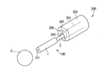
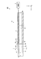
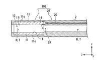
- FIG. 1 shows the whole structure of the calculus crushing system provided with the ultrasonic treatment tool which concerns on 1st embodiment of this invention. It is a perspective view of the tip of the endoscope insertion part which opposes the calculus of a crushing object. It is a block diagram of the ultrasonic oscillating part of the ultrasonic treatment instrument. It is a sectional view of the ultrasonic oscillating part in which the cavity was filled with liquid. It is sectional drawing of the modification of the insertion part of the ultrasonic treatment instrument. It is sectional drawing of the modification of the insertion part of the ultrasonic treatment instrument. It is a block diagram of the ultrasonic treatment instrument which concerns on 2nd embodiment of this invention.
- FIG. 1 is a diagram showing an overall configuration of a calculus crushing system 300.
- the calculus breaking system (endoscopic treatment system) 300 includes an endoscope 200 inserted into the urethra U and an ultrasonic treatment instrument 100 inserted into a channel of the endoscope 200. I have it.
- the endoscope 200 is appropriately selected from known flexible ureteroscopes including a long endoscope insertion portion 202 having a treatment instrument channel 201 through which a treatment instrument can be inserted.
- the endoscope 200 has an operation unit 204 at the base end.
- the operation section 204 is provided with a treatment instrument insertion hole 205, and the ultrasonic treatment instrument 100 is inserted into the treatment instrument channel 201 through the treatment instrument insertion hole 205.
- FIG. 2 is a perspective view of the tip of the endoscope insertion portion 202 facing the calculus C to be crushed.
- the endoscope 200 has an illumination 206 and an imaging unit 207 at the tip of the endoscope insertion unit 202.
- the tip of the ultrasonic treatment instrument 100 inserted into the treatment instrument channel 201 projects from the treatment instrument channel opening 203 at the tip of the endoscope insertion portion 202.
- the endoscope 200 sends water into the body by discharging the water conveyed via the treatment instrument channel 201 from the treatment instrument channel opening 203.
- the water discharged from the treatment tool channel opening 203 is perfused through a separately provided drainage channel or the like.
- the water supply channel and the water supply channel opening are provided in the endoscope 200, and the water conveyed through the water supply channel is discharged into the body by being discharged from the water supply channel opening at the tip of the endoscope 200. Also good.
- the water discharged from the water supply channel opening is perfused through the treatment tool channel 201, a separately provided drainage channel, and the like.
- the endoscope 200 is connected to an endoscope system 210 as shown in FIG.
- the endoscope system 210 includes a light source that provides light to the illumination 206 of the endoscope 200, an image processing circuit that performs image processing on an image captured by the image capturing unit 207, and displays the image on a monitor.
- the ultrasonic treatment instrument 100 includes an insertion section 10 having an ultrasonic wave oscillating section 1 and a flexible tube section 2, and a drive section 3.
- the ultrasonic treatment tool 100 is a treatment tool that performs treatment by generating ultrasonic waves from the ultrasonic wave oscillating unit 1 to the affected area.
- FIG. 3 is a configuration diagram of the ultrasonic wave oscillating unit 1 of the ultrasonic treatment instrument 100.
- the ultrasonic wave oscillating unit 1 is a cylindrical member provided at the tip of the flexible tube unit 2 and generates ultrasonic waves for the calculus C.
- the ultrasonic oscillator 1 has a piezoelectric element 11.
- the longitudinal direction of the ultrasonic oscillator 1 is also referred to as the Z-axis direction
- the plane perpendicular to the Z-axis direction is also referred to as the XY plane.
- the irradiation direction of ultrasonic waves (one side in the Z-axis direction) is referred to as “tip side”, and the opposite side (the other side in the Z-axis direction) is referred to as “proximal side”.
- the piezoelectric element 11 is a cylindrical element having a cavity H inside, and is a passive element that utilizes the piezoelectric effect of converting voltage into force.
- the piezoelectric element 11 is made of, for example, ceramics.
- the polarization direction is the thickness direction connecting the inner peripheral surface 11i and the outer peripheral surface 11o, and vibrates (breathing vibration) in the longitudinal direction.
- the cavity H has only a first opening 13 formed at the tip of the piezoelectric element 11 and a second opening 14 formed at the base end.
- the flexible tube portion (long portion) 2 is a tubular member formed of a flexible material such as silicone, and has a conduit D penetrating from the distal end to the proximal end.
- the conduit D has only a third opening 23 formed at the tip of the flexible tube portion 2 and a fourth opening 24 formed at the base end.
- the third opening 23 communicates with the second opening 14 of the piezoelectric element 11.
- the cavity H and the conduit D form a “through hole T” that penetrates from the first opening 13 to the fourth opening 24.
- the flexible tube section 2 has a coaxial cable 20.
- the coaxial cable 20 is embedded in the flexible tube portion 2 along the longitudinal direction of the flexible tube portion 2 from the tip to the base end.
- the coaxial cable 20 may be provided by inserting the conduit D.
- a first conductive wire 21 and a second conductive wire 22 for transmitting electric power to the piezoelectric element 11 are inserted inside the coaxial cable 20.
- the first conductive wire 21 is one of the positive electrode and the negative electrode
- the second conductive wire 22 is the other of the positive electrode and the negative electrode.
- the tip of the first conductive wire 21 is connected to the inner peripheral surface 11i of the piezoelectric element 11.
- the base end of the first conductive wire 21 is attached to the drive unit 3.
- the tip of the second conductive wire 22 is connected to the outer peripheral surface 11o of the piezoelectric element 11.
- the base end of the second conductive wire 22 is attached to the drive unit 3.
- the polarization direction of the piezoelectric element 11 is the thickness direction (longitudinal direction) connecting the inner peripheral surface 11i and the outer peripheral surface 11o.
- the piezoelectric element 11 vibrates in the longitudinal direction (breathing vibration) due to the piezoelectric effect when a voltage is applied from the first conductive wire 21 and the second conductive wire 22.
- the driving unit 3 applies a voltage to the piezoelectric element 11 of the ultrasonic wave oscillating unit 1 via the first conductive wire 21 and the second conductive wire 22 that pass through the flexible tube section 2. It is a device.
- the drive unit 3 has a switch or the like (not shown), and an operator can operate the switch and control the application of voltage to the piezoelectric element 11.
- FIG. 4 is a cross-sectional view of the ultrasonic wave oscillating unit 1 in which the cavity H is filled with the liquid L.
- the liquid L such as physiological saline flows in from the first opening 13
- the liquid L flows into the cavity H.
- the second opening 14 of the piezoelectric element 11 communicates with the third opening 23 of the conduit D
- the gas existing in the cavity H passes through the third opening 23 and moves to the base end side. Therefore, the liquid L easily flows into the cavity H of the piezoelectric element 11.
- the cavity H of the piezoelectric element 11 is filled with the liquid L.
- the ultrasonic wave generated by the respiratory vibration of the piezoelectric element 11 is suitably transmitted to the tip side via the liquid L filling the cavity H.
- the operator causes the ultrasonic wave oscillating section 1 of the ultrasonic treatment instrument 100 to protrude from the treatment instrument channel opening 203 at the tip of the endoscope insertion section 202, as shown in FIG.
- the operator further brings the first opening 13 of the ultrasonic wave oscillating unit 1 closer to the calculus C to be crushed while checking the image displayed on the monitor.
- the liquid L discharged from the treatment instrument channel 201 flows in from the first opening 13. Part of the liquid L flows into the conduit D.
- the fourth opening 24 is arranged outside the body, and the gas inside the through hole T easily moves to the base end side, and the liquid L easily flows into the cavity H of the piezoelectric element 11. As a result, the cavity H surrounded by the inner peripheral surface 11i of the piezoelectric element 11 is filled with the liquid L.
- the surgeon operates a switch or the like provided on the drive unit 3 to apply a voltage to the piezoelectric element 11.
- the piezoelectric element 11 breathes and vibrates in the radial direction by the piezoelectric effect to generate ultrasonic waves.
- the generated ultrasonic waves are emitted from the first opening 13 to the tip side via the liquid L filled in the cavity H.
- the fragments of the calculus C crushed by ultrasonic waves are collected together with the liquid L that flows back through the treatment tool channel 201, a drainage channel separately provided, and the like.
- the piezoelectric element 11 has a tubular shape, and it is easy to reduce the diameter. Further, even if the piezoelectric element 11 has a small diameter, it is easy to fill the inside of the cavity H with the liquid L, and the ultrasonic wave generated by the piezoelectric element 11 is passed through the liquid L to the first opening. It can be suitably transmitted from 13 to the tip side.
- the piezoelectric element 11 was made of ceramics, but the piezoelectric element according to the present invention is not limited to this.
- the piezoelectric element according to the present invention may be formed of a passive element other than ceramics, for example, a single crystal material.
- the piezoelectric element 11 was formed in a cylindrical shape, but the piezoelectric element and the outer cylinder according to the present invention are not limited to this.
- the piezoelectric element and the outer cylinder according to the present invention may be formed in a rectangular tube shape, for example.
- the ultrasonic wave oscillating unit 1 was provided at the tip of the flexible tube unit 2, but the modes of the ultrasonic wave oscillating unit and the flexible tube unit according to the present invention are not limited to this.
- the flexible tube portion 2B which is a modified example of the flexible tube portion 2 holds the outer peripheral surface 11o of the piezoelectric element 11 of the ultrasonic oscillator 1. ing.
- the insertion portion 10B can stably hold the piezoelectric element 11.
- the ultrasonic oscillating unit 1 has only the piezoelectric element 11, but the mode of the ultrasonic oscillating unit according to the present invention is not limited to this.
- an insertion portion 10C which is a modified example of the insertion portion 10 shown in FIG. 6
- an ultrasonic oscillating portion 1B which is a modified example of the ultrasonic oscillating portion 1 has an outer cylinder 12 on the outer circumference of a piezoelectric element 11.
- the outer cylinder 12 is a hard member, and forms an acoustic insulating layer A in which air or the like can exist between the inner peripheral surface 12i of the outer cylinder 12 and the outer peripheral surface 11o of the piezoelectric element 11.
- the acoustic insulating layer A may be a layer in which ultrasonic waves are not easily transmitted, and may be a gas layer in which only air is present, or may be a layer formed of a low acoustic impedance material in which ultrasonic waves are not easily transmitted. ..
- the acoustic insulating layer A may be formed of, for example, a sponge-like member in which air and a member other than air are interposed.
- the outer peripheral surface 11o of the piezoelectric element 11 is surrounded by the acoustic insulating layer A over the entire circumference, and it is difficult for ultrasonic waves to propagate.
- FIG. 7 is a configuration diagram of the ultrasonic treatment device 100B.
- the ultrasonic treatment instrument 100B according to the present embodiment includes an insertion section 10 having an ultrasonic wave oscillating section 1 and a flexible tube section 2, a drive section 3, and a pump 5.
- the pump (suction device, water supply device) 5 is connected to the fourth opening 24 formed at the base end of the flexible tube portion 2 by a tube.
- the pump 5 can also suck the water inside the conduit D, and can also send water (physiological saline) to the conduit D of the flexible tube portion 2.
- the pump 5 can reliably draw the liquid L to the pipeline D by sucking the air inside the pipeline D.
- the cavity H surrounded by the inner peripheral surface 11i of the piezoelectric element 11 is filled with the liquid L. It is sufficient that at least the cavity H of the piezoelectric element 11 is filled with the liquid L, and it is not necessary to fill the entire conduit D with the liquid L.
- the pump 5 can fill the cavity H surrounded by the inner peripheral surface 11i of the piezoelectric element 11 with the fed water by feeding the water into the pipeline D. It is desirable that the water to be sent is degassed water that does not contain bubbles because it serves as an ultrasonic wave transmission medium.
- the through hole T (the conduit D and the cavity H) is filled with the water from the pump 5, so that the pump 5 It is possible to prevent the air in the through hole T (the pipe D and the cavity H) from being discharged from the first opening 13 when the water is sent.
- the pump 5 can be used for purposes other than filling the cavity H of the piezoelectric element 11 with the liquid L.
- the pump 5 may additionally supply water to supplement the liquid L in the cavity H during the operation.
- the pump 5 may perfuse water in order to collect the fragments of the calculus C crushed by ultrasonic waves.
- the cavity H can be reliably filled with the liquid L, and the ultrasonic waves generated by the piezoelectric element 11 are passed from the first opening 13 to the tip side via the liquid L. It can be transmitted appropriately.
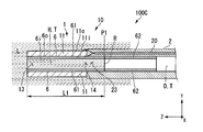
- FIG. 8 is a partial cross-sectional view of the ultrasonic treatment device 100C.
- the ultrasonic treatment device 100C according to the present embodiment includes an insertion portion 10 having an ultrasonic wave oscillating portion 1 and a flexible tube portion 2, a drive portion 3, and a thin film tube 6.
- the thin film tube 6 is a long and elastic tube member.
- the thin film tube 6 is provided inside the through hole T and over a region from the first opening 13 of the through hole T to a predetermined position of the through hole T.
- the thin film tube 6 does not necessarily have to be provided from the first opening 13 to the fourth opening 24.
- the outer peripheral surface 6o of the thin film tube 6 is in contact with the inner peripheral surface of the through hole T.
- the thin film tube 6 has a hydrophilic treatment area 61 having an inner peripheral surface 6i subjected to hydrophilic treatment, and a water repellent treatment area 62 having an inner peripheral surface 6i subjected to water repellent treatment.
- the hydrophilic treatment area 61 is arranged on the front end side, and the water repellent treatment area 62 is arranged on the base end side.
- a boundary surface between the liquid L and the gas is formed at the boundary between the hydrophilic treatment area 61 and the water repellent treatment area 62 (hereinafter referred to as “reflection surface formation position P1”).
- the boundary surface functions as a “reflection surface R” that reflects ultrasonic waves.
- the ultrasonic wave generated by the piezoelectric element 11 is also transmitted to the base end side from the second opening 14, but the reflecting surface R reflects the ultrasonic wave transmitted to the base end side to the distal end side, and the first opening 13 It is possible to increase the output of ultrasonic waves transmitted from.
- the radial resonance frequency of the cylindrical liquid L formed from the first opening 13 to the reflection surface R is equal to that of the piezoelectric element 11. It is desirable that the length be equal to the resonance frequency in the radial direction.
- the length of the distance L1 at which the radial resonance frequency of the cylindrical liquid L formed from the first opening 13 to the reflecting surface R is equal to the radial resonance frequency of the piezoelectric element 11 is the piezoelectric element.
- the distance L1 may be one selected from the candidates, but it is more preferably a length at which resonance occurs in the low order mode. This is because it is easier to crush the calculus C when the resonance is generated in the low order mode.
- the reflection surface forming position P1 may be on the cavity H side or on the conduit D side.
- the cavity H can be reliably filled with the liquid L, and the ultrasonic waves generated by the piezoelectric element 11 are passed from the first opening 13 to the tip side via the liquid L. It can be transmitted appropriately.
- the reflecting surface R is formed at the boundary between the liquid L and the gas, and the ultrasonic wave transmitted to the proximal end side is reflected to the distal end side and transmitted from the first opening 13.
- the output of the ultrasonic waves generated can be increased.
- the hydrophilic treatment region 61 and the water repellent treatment region 62 were provided on the inner peripheral surface 6i of the thin film tube, but the aspect of the hydrophilic treatment region and the water repellent treatment region according to the present invention is not limited to this. Not done.
- the hydrophilic treatment region or the water repellent treatment region according to the present invention may be a region in which the inner peripheral surface of the through hole T is directly subjected to the hydrophilic coating or the water repellent coating.
- the hydrophilic treatment area 61 and the water repellent treatment area 62 are provided in the through hole T, but the water repellent treatment area 62 is not always necessary. If the hydrophilic treatment area 61 is more hydrophilic than the portion other than the hydrophilic treatment area 61, the cavity H can be easily filled with the liquid L, and the reflecting surface R can be formed.
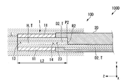
- FIG. 9 is a partial configuration diagram of the ultrasonic treatment device 100D.
- the ultrasonic treatment instrument 100D according to the present embodiment includes an insertion section 10D having an ultrasonic wave oscillating section 1 and a flexible tube section 2D, and a drive section 3.
- the flexible tube portion 2D is a tubular member formed of a flexible material such as silicone, and has a conduit D2 penetrating from the distal end to the proximal end. Only the third opening 23 formed at the tip of the flexible tube portion 2 and the fourth opening 24 formed at the base end of the duct D2 are opened. The third opening 23 communicates with the second opening 14 of the piezoelectric element 11.
- the conduit D2 is bent at a position at a distance L2 from the first opening 13.
- a part of the bent portion of the conduit D2 forms a "reflection surface R2" that is substantially perpendicular to the z-axis.
- the reflecting surface R2 can reflect the ultrasonic wave transmitted to the base end side to the distal end side and increase the output of the ultrasonic wave transmitted from the first opening 13.
- the reflecting surface R2 may be tilted instead of being perpendicular to the z axis.
- the distance L2 is preferably a length at which the radial resonance frequency of the cylindrical liquid L formed from the first opening 13 to the reflecting surface R2 is equal to the radial resonance frequency of the piezoelectric element 11. ..
- the piezoelectric element 11 When the piezoelectric element 11 generates ultrasonic waves, the piezoelectric element 11 and the liquid L are simultaneously in a resonance state, so that highly efficient ultrasonic waves with large displacement per applied voltage can be generated.
- the reflective surface R2 is made of a material having higher hardness, the reflectance of the ultrasonic wave on the reflective surface R2 can be increased and the output of the ultrasonic wave transmitted from the first opening 13 can be increased.
- the cavity H can be reliably filled with the liquid L, and the ultrasonic waves generated by the piezoelectric element 11 are passed from the first opening 13 to the tip side via the liquid L. It can be transmitted appropriately.
- the reflecting surface R2 is formed, the ultrasonic wave transmitted to the proximal end side is reflected to the distal end side, and the output of the ultrasonic wave transmitted from the first opening 13 is increased. be able to.
- the reflecting surface according to the present invention may be a wall portion formed in the through hole T.
- a water passage hole through which the liquid L can pass is formed in the wall portion, and the liquid L can move to the base end side as in the above embodiment.
- the ultrasonic wave transmitted to the base end side can be reflected to the tip end side by the reflection surface formed by the wall portion.
- FIGS. 10 to 11 A fifth embodiment of the present invention will be described with reference to FIGS. 10 to 11. In the following description, the same components as those already described will be assigned the same reference numerals and overlapping description will be omitted. This embodiment is different from the first embodiment in that a suction unit is further included.
- FIG. 10 is a configuration diagram of the ultrasonic treatment device 100E.
- the ultrasonic treatment instrument 100E according to the present embodiment includes an insertion section 10 having an ultrasonic wave oscillating section 1 and a flexible tube section 2, a drive section 3, and a suction section 7.
- the suction part 7 has a thin film tube 71, a rubber stopper 72, and a tow string 73.
- the suction unit 7 is a device that is provided inside the cavity H and the conduit D and that sucks the liquid L toward the proximal end side.
- the thin film tube 71 is a long and elastic tube member.
- the thin film tube 71 is provided inside the through hole T and extends over a region from the first opening 13 of the through hole T to a predetermined position of the through hole T.
- the thin film tube 71 does not necessarily have to be provided from the first opening 13 to the fourth opening 24.
- the outer peripheral surface 71o of the thin film tube 71 is in contact with the inner peripheral surface 11i of the piezoelectric element 11 and the inner peripheral surface 2i of the flexible tube portion 2. Further, the thin film tube 71 has a convex portion 71P that engages with the rubber plug 72.
- the rubber stopper 72 is a columnar member having elasticity and is arranged inside the thin film tube 71.
- the outer peripheral surface 72o of the rubber stopper 72 is in contact with the inner peripheral surface 71i of the thin film tube 71.
- the diameter dimension of the rubber plug 72 before being placed in the thin film tube 71 is slightly larger than the inner diameter of the thin film tube 71. Therefore, the outer peripheral surface 72o of the rubber stopper 72 arranged on the thin film tube 71 is in close contact with the inner peripheral surface 71i of the thin film tube 71.
- the tow string 73 is a string connected to the base end side of the rubber plug 72.
- the operator can slide the rubber plug 72 toward the proximal end by pulling the tow string 73 toward the proximal end.
- the operator can pull the pull cord 73 until the rubber plug 72 and the convex portion 71P are engaged with each other.
- FIG. 11 is a cross-sectional view of the insertion portion 10 when the rubber plug 72 is pulled toward the base end side.
- the liquid L is sucked into the cavity H and the conduit D by pulling the rubber plug 72 toward the base end side.
- the region from the first opening 13 to the tip of the rubber stopper 72 can be filled with the liquid L.
- the pull cord 73 is pulled to a position where the rubber plug 72 and the convex portion 71P are engaged with each other.
- the tip of the rubber plug 72 forms a “reflection surface R3”.
- the reflecting surface R3 can reflect the ultrasonic wave transmitted to the base end side to the distal end side and increase the output of the ultrasonic wave transmitted from the first opening 13.
- the distance L3 in the Z-axis direction from the first opening 13 to the tip of the rubber plug 72 (reflection surface formation position P3) is the radial resonance of the cylindrical liquid L formed from the first opening 13 to the reflection surface R3. It is desirable that the frequency has a length that is equal to the radial resonance frequency of the piezoelectric element.
- the cavity H can be surely filled with the liquid L without using a pump, and the ultrasonic wave generated by the piezoelectric element 11 is first transmitted through the liquid L. It can be suitably transmitted from the opening 13 to the tip side.
- the reflecting surface R3 can reflect the ultrasonic wave transmitted to the proximal end side to the distal end side and increase the output of the ultrasonic wave transmitted from the first opening 13. ..
- the present invention can be applied to an ultrasonic treatment tool that is used by inserting it into the body.
Landscapes
- Health & Medical Sciences (AREA)
- Life Sciences & Earth Sciences (AREA)
- General Health & Medical Sciences (AREA)
- Animal Behavior & Ethology (AREA)
- Surgery (AREA)
- Veterinary Medicine (AREA)
- Engineering & Computer Science (AREA)
- Biomedical Technology (AREA)
- Public Health (AREA)
- Nuclear Medicine, Radiotherapy & Molecular Imaging (AREA)
- Medical Informatics (AREA)
- Molecular Biology (AREA)
- Orthopedic Medicine & Surgery (AREA)
- Heart & Thoracic Surgery (AREA)
- Vascular Medicine (AREA)
- Radiology & Medical Imaging (AREA)
- Surgical Instruments (AREA)
Abstract
超音波処置具は、体内で超音波を伝搬させて処置する超音波処置具であって、先端の第一開口および基端の第二開口が開口する空洞を有する筒形状であり、分極方向が内周面と外周面とを結ぶ厚み方向である圧電素子と、前記圧電素子の基端に接続され、先端に設けられた第三開口から基端に設けられた第四開口まで貫通する管路を有し、前記第三開口が前記第二開口と連通し、前記第四開口が体外に配置される長尺部と、を備え、前記第一開口から前記第四開口まで貫通する貫通孔を形成する。
Description
本発明は、超音波処置具に関する。
尿路に形成された結石を破砕する尿路結石治療においては、尿路内に処置具の先端部を挿入して結石を破砕する経尿道的結石破砕術が主流となってきている。経尿道的結石破砕術に用いる処置具は、結石破砕性能が高いことが必要とされており、また、先端が細径であり内視鏡のチャネルを挿通可能であることも必要とされている。
特許文献1には、先端が細径であり、高出力が可能な超音波処置具が記載されている。特許文献1の超音波処置具は、円筒形状の圧電素子からなる超音波振動子を挿入部の先端に有しており、超音波振動子を冷却水に満たした状態で、超音波振動子から超音波を患部に向けて放射する。円筒形状の圧電素子からなる超音波振動子は、径寸法が小さく形成されており、体腔内を挿通させやすい。
尿路に処置具を挿入する際には、処置具は細径であり、内視鏡のチャネルを挿通可能であることが必要とされている。しかしながら、特許文献1の超音波処置具は、細径にするほど圧電素子の内部に冷却水が入りにくく、発生させた超音波を冷却水経由で伝達させることが難しい。そのため、圧電素子の細径化と高出力とを共に実現することが難しかった。
上記事情を踏まえ、本発明は、細径かつ高出力な超音波処置具を提供することを目的とする。
上記課題を解決するために、この発明は以下の手段を提案している。
本発明の第一の態様に係る超音波処置具は、体内で超音波を伝搬させて処置する超音波処置具であって、先端の第一開口および基端の第二開口が開口する空洞を有する筒形状であり、分極方向が内周面と外周面とを結ぶ厚み方向である圧電素子と、前記圧電素子の基端に接続され、先端に設けられた第三開口から基端に設けられた第四開口まで貫通する管路を有し、前記第三開口が前記第二開口と連通し、前記第四開口が体外に配置される長尺部と、を備え、前記第一開口から前記第四開口まで貫通する貫通孔を形成する。
本発明の第一の態様に係る超音波処置具は、体内で超音波を伝搬させて処置する超音波処置具であって、先端の第一開口および基端の第二開口が開口する空洞を有する筒形状であり、分極方向が内周面と外周面とを結ぶ厚み方向である圧電素子と、前記圧電素子の基端に接続され、先端に設けられた第三開口から基端に設けられた第四開口まで貫通する管路を有し、前記第三開口が前記第二開口と連通し、前記第四開口が体外に配置される長尺部と、を備え、前記第一開口から前記第四開口まで貫通する貫通孔を形成する。
本発明の第二の態様によれば、第一の態様に係る超音波処置具において、前記第四開口に接続され、前記貫通孔の内部の空気を吸引する吸引装置を備えてもよい。
本発明の第三の態様によれば、第一の態様に係る超音波処置具において、前記第四開口に接続され、前記貫通孔の内部に送水する送水装置を備えてもよい。
本発明の第四の態様によれば、第一の態様に係る超音波処置具において、前記貫通孔の前記第一開口から前記貫通孔の所定の位置までの領域にわたって、先端側に配置された親水処理領域と、基端側に配置された撥水処理領域とを有し、前記親水処理領域は、前記撥水処理領域よりも親水性が高くてもよい。
本発明の第五の態様によれば、第四の態様に係る超音波処置具において、前記親水処理領域および前記撥水処理領域は、前記貫通孔の内部に設けられた薄膜チューブの内周面に形成されてもよい。
本発明の第六の態様によれば、第四または第五の態様に係る超音波処置具において、前記第一開口から前記親水処理領域と前記撥水処理領域との境界までの距離は、前記第一開口から前記境界までに形成される円柱状の液体の径方向の共振周波数が、前記圧電素子の径方向の共振周波数と同等になる長さであってもよい。
本発明の第七の態様によれば、第一の態様に係る超音波処置具において、前記貫通孔は、前記圧電素子の長手方向に対して略垂直な反射面を有してもよい。
本発明の第八の態様によれば、第七の態様に係る超音波処置具において、前記第一開口から前記反射面までの距離は、前記第一開口から前記反射面までに形成される円柱状の液体の径方向の共振周波数が、前記圧電素子の径方向の共振周波数と同等になる長さであってもよい。
本発明の第九の態様によれば、第一の態様に係る超音波処置具において、前記第一開口を密閉する栓を有し、前記栓を基端側から牽引可能な紐を有してもよい。
本発明の第十の態様によれば、第九の態様に係る超音波処置具において、前記栓を基端側に牽引した際に前記栓と係合して前記栓の基端への移動を制限する凸部を有してもよい。
本発明の第十一の態様によれば、第十の態様に係る超音波処置具において、前記栓と前記凸部とが係合した際、前記第一開口から前記栓の先端までの距離は、前記第一開口から前記栓の先端までに形成される円柱状の液体の径方向の共振周波数が、前記圧電素子の径方向の共振周波数と同等になる長さであってもよい。
本発明の第十二の態様に係る内視鏡処置システムは、第一から第十一のいずれかの態様に係る超音波処置具と、前記超音波処置具が挿通可能なチャネルを有する内視鏡と、を備える。
本発明の超音波処置具によれば、細径かつ高出力な超音波処置具を提供することができる。
(第一実施形態)
本発明の第一実施形態に係る超音波処置具100について、図1から図4を参照して以下に説明する。
本発明の第一実施形態に係る超音波処置具100について、図1から図4を参照して以下に説明する。
[結石破砕システム300]
図1は、結石破砕システム300の全体構成を示す図である。
結石破砕システム(内視鏡処置システム)300は、図1に示すように、尿道Uに挿入される内視鏡200と、内視鏡200のチャネルに挿通される超音波処置具100と、を備えている。
図1は、結石破砕システム300の全体構成を示す図である。
結石破砕システム(内視鏡処置システム)300は、図1に示すように、尿道Uに挿入される内視鏡200と、内視鏡200のチャネルに挿通される超音波処置具100と、を備えている。
[内視鏡200]
内視鏡200は、処置具が挿通可能な処置具チャネル201を有する長尺の内視鏡挿入部202を備えた公知の軟性尿管鏡の中から、適宜選択したものである。内視鏡200は、基端に操作部204を有している。操作部204には処置具挿入孔205が設けられており、処置具挿入孔205から超音波処置具100が処置具チャネル201に挿入される。
内視鏡200は、処置具が挿通可能な処置具チャネル201を有する長尺の内視鏡挿入部202を備えた公知の軟性尿管鏡の中から、適宜選択したものである。内視鏡200は、基端に操作部204を有している。操作部204には処置具挿入孔205が設けられており、処置具挿入孔205から超音波処置具100が処置具チャネル201に挿入される。
図2は、破砕対象の結石Cと対向する内視鏡挿入部202の先端の斜視図である。
内視鏡200は、内視鏡挿入部202の先端に照明206や撮像部207を有している。処置具チャネル201に挿入された超音波処置具100の先端は、内視鏡挿入部202の先端の処置具チャネル開口203から突出する。
内視鏡200は、内視鏡挿入部202の先端に照明206や撮像部207を有している。処置具チャネル201に挿入された超音波処置具100の先端は、内視鏡挿入部202の先端の処置具チャネル開口203から突出する。
内視鏡200は、処置具チャネル201を経由して搬送された水が、処置具チャネル開口203から排出されることで、体内に送水を行う。処置具チャネル開口203から排出された水は、別途に設けられた排水チャネル等を経由して灌流する。
なお、内視鏡200に、送水チャネル、送水チャネル開口を設けて、送水チャネルを経由して搬送された水が、内視鏡200先端の送水チャネル開口から排出されることによって体内に送水することとしても良い。この場合、送水チャネル開口から排出された水は、処置具チャネル201や別途設けられた排水チャネル等を経由して灌流する。
なお、内視鏡200に、送水チャネル、送水チャネル開口を設けて、送水チャネルを経由して搬送された水が、内視鏡200先端の送水チャネル開口から排出されることによって体内に送水することとしても良い。この場合、送水チャネル開口から排出された水は、処置具チャネル201や別途設けられた排水チャネル等を経由して灌流する。
内視鏡200は、図1に示すように、内視鏡システム210に接続されている。内視鏡システム210は、内視鏡200の照明206に光を提供する光源や、撮像部207が撮像した画像を画像処理してモニタに表示する画像処理回路等を備えている。
[超音波処置具100]
超音波処置具100は、超音波発振部1と可撓管部2とを有する挿入部10と、駆動部3と、を備えている。超音波処置具100は、超音波発振部1から患部に対して超音波を発生させて処置を行う処置具である。
超音波処置具100は、超音波発振部1と可撓管部2とを有する挿入部10と、駆動部3と、を備えている。超音波処置具100は、超音波発振部1から患部に対して超音波を発生させて処置を行う処置具である。
図3は、超音波処置具100の超音波発振部1の構成図である。
超音波発振部1は、可撓管部2の先端に設けられた筒形状の部材であり、結石Cに対して超音波を発生させる。超音波発振部1は、圧電素子11を有している。
以降の説明において、超音波発振部1の長手方向をZ軸方向、Z軸方向に垂直な平面をXY平面とも称す。また、超音波発振部1において、超音波の照射方向(Z軸方向の一方側)を「先端側」、その反対側(Z軸方向の他方側)を「基端側」と称す。
超音波発振部1は、可撓管部2の先端に設けられた筒形状の部材であり、結石Cに対して超音波を発生させる。超音波発振部1は、圧電素子11を有している。
以降の説明において、超音波発振部1の長手方向をZ軸方向、Z軸方向に垂直な平面をXY平面とも称す。また、超音波発振部1において、超音波の照射方向(Z軸方向の一方側)を「先端側」、その反対側(Z軸方向の他方側)を「基端側」と称す。
圧電素子11は、空洞Hを内部に有する円筒形状であり、電圧を力に変換する圧電効果を利用した受動素子である。圧電素子11は、例えばセラミックスで形成されている。圧電素子11は、分極方向が内周面11iと外周面11oとを結ぶ厚み方向であり、経方向に振動(呼吸振動)する。空洞Hは、圧電素子11の先端に形成された第一開口13と、基端に形成された第二開口14のみが開口している。
可撓管部(長尺部)2は、例えばシリコーン等の可撓性を有する材料で形成された管状部材であり、先端から基端まで貫通する管路Dを有する。管路Dは、可撓管部2の先端に形成された第三開口23と、基端に形成された第四開口24のみが開口する。第三開口23は、圧電素子11の第二開口14と連通している。
空洞Hおよび管路Dは、第一開口13から第四開口24まで貫通する「貫通孔T」を形成する。
可撓管部2は、同軸ケーブル20を有している。同軸ケーブル20は、先端から基端まで、可撓管部2の長手方向に沿って可撓管部2に埋め込まれている。なお、同軸ケーブル20は、管路Dを挿通して設けられていてもよい。
同軸ケーブル20の内部には圧電素子11に電力を伝達する第一導電線21および第二導電線22が挿通している。第一導電線21が正極または負極の一方であり、第二導電線22が正極または負極の他方である。
第一導電線21の先端は、圧電素子11の内周面11iに接続されている。一方、第一導電線21の基端は、駆動部3に取り付けられている。
第二導電線22の先端は、圧電素子11の外周面11oに接続されている。一方、第二導電線22の基端は、駆動部3に取り付けられている。
圧電素子11の分極方向は、内周面11iと外周面11oとを結ぶ厚み方向(経方向)となる。圧電素子11は、第一導電線21および第二導電線22から電圧が加えられることで、圧電効果により経方向に振動(呼吸振動)する。
駆動部3は、図3に示すように、可撓管部2を挿通する第一導電線21および第二導電線22を経由して、超音波発振部1の圧電素子11に電圧を印加する装置である。駆動部3は、不図示のスイッチ等を有しており、術者がスイッチを操作すること、圧電素子11への電圧の印加を制御することができる。
図4は、空洞Hが液体Lで満たされた超音波発振部1の断面図である。
第一開口13から生理食塩水等の液体Lが流入した場合、液体Lは空洞Hに流入する。圧電素子11の第二開口14は、管路Dの第三開口23と連通しているため、空洞Hに存在していた気体は第三開口23を通過して、基端側に移動する。そのため、圧電素子11の空洞Hに液体Lが流入しやすい。その結果、圧電素子11の空洞Hは液体Lで満たされる。圧電素子11の呼吸振動により発生した超音波は、空洞Hを満たした液体Lを経由して、先端側に好適に伝達される。
第一開口13から生理食塩水等の液体Lが流入した場合、液体Lは空洞Hに流入する。圧電素子11の第二開口14は、管路Dの第三開口23と連通しているため、空洞Hに存在していた気体は第三開口23を通過して、基端側に移動する。そのため、圧電素子11の空洞Hに液体Lが流入しやすい。その結果、圧電素子11の空洞Hは液体Lで満たされる。圧電素子11の呼吸振動により発生した超音波は、空洞Hを満たした液体Lを経由して、先端側に好適に伝達される。
[超音波処置具100の動作]
次に、超音波処置具100の動作について説明する。
術者は、尿道Uに内視鏡200の内視鏡挿入部202を挿入し、膀胱Bの尿管口Oから尿管または腎臓Kまで内視鏡挿入部202の先端を挿入する。術者はモニタに表示された撮像部207が撮像した画像を確認しながら、内視鏡挿入部202の先端を破砕対象の結石Cに接近させる。
次に、超音波処置具100の動作について説明する。
術者は、尿道Uに内視鏡200の内視鏡挿入部202を挿入し、膀胱Bの尿管口Oから尿管または腎臓Kまで内視鏡挿入部202の先端を挿入する。術者はモニタに表示された撮像部207が撮像した画像を確認しながら、内視鏡挿入部202の先端を破砕対象の結石Cに接近させる。
術者は、超音波処置具100の超音波発振部1を、図2に示すように、内視鏡挿入部202の先端の処置具チャネル開口203から突出させる。術者は、超音波発振部1の第一開口13を、モニタに表示された画像を確認しながら、破砕対象の結石Cにさらに接近させる。
第一開口13からは、処置具チャネル201から排出される液体Lが流入する。一部の液体Lは、管路Dまで流入する。第四開口24は体外に配置されており、貫通孔Tの内部の気体が基端側に移動しやすく、圧電素子11の空洞Hに液体Lが流入しやすい。その結果、圧電素子11の内周面11iに囲まれた空洞Hは液体Lで充填される。
術者は、駆動部3に設けられたスイッチ等を操作して、圧電素子11へ電圧を印加する。その結果、圧電素子11は、圧電効果により径方向に呼吸振動して超音波を発生させる。発生した超音波は、空洞Hの内部に充填された液体Lを介して第一開口13から先端側に発せされる。
超音波によって破砕された結石Cの破片は、処置具チャネル201や別途に設けられた排水チャネル等を経由して還流する液体Lとともに回収される。
本実施形態の超音波処置具100によれば、圧電素子11は筒形状であり細径化しやすい。また、圧電素子11が細径であったとしても、空洞Hの内部に液体Lを充填されることが容易であり、圧電素子11が発生させた超音波を液体Lを経由して第一開口13から先端側に好適に伝達させることができる。
以上、本発明の第一実施形態について図面を参照して詳述したが、具体的な構成はこの実施形態に限られるものではなく、本発明の要旨を逸脱しない範囲の設計変更等も含まれる。また、上述の実施形態および変形例において示した構成要素は適宜に組み合わせて構成することが可能である。
(変形例1)
例えば、上記実施形態において、圧電素子11はセラミックスによって形成されていたが、本発明に係る圧電素子はこれに限定されない。本発明に係る圧電素子は、セラミックス以外の受動素子、例えば単結晶材料によって形成されていてもよい。
例えば、上記実施形態において、圧電素子11はセラミックスによって形成されていたが、本発明に係る圧電素子はこれに限定されない。本発明に係る圧電素子は、セラミックス以外の受動素子、例えば単結晶材料によって形成されていてもよい。
(変形例2)
例えば、上記実施形態において、圧電素子11は円筒形状に形成されていたが、本発明に係る圧電素子および外筒はこれに限定されない。本発明に係る圧電素子および外筒は、例えば角筒形状に形成されていてもよい。
例えば、上記実施形態において、圧電素子11は円筒形状に形成されていたが、本発明に係る圧電素子および外筒はこれに限定されない。本発明に係る圧電素子および外筒は、例えば角筒形状に形成されていてもよい。
(変形例3)
例えば、上記実施形態において、超音波発振部1は可撓管部2の先端に設けられていたが、本発明に係る超音波発振部と可撓管部の態様はこれに限定されない。図5に示す挿入部10の変形例である挿入部10Bにおいて、可撓管部2の変形例である可撓管部2Bは、超音波発振部1の圧電素子11の外周面11oを保持している。挿入部10Bは、圧電素子11を安定して保持することができる。
例えば、上記実施形態において、超音波発振部1は可撓管部2の先端に設けられていたが、本発明に係る超音波発振部と可撓管部の態様はこれに限定されない。図5に示す挿入部10の変形例である挿入部10Bにおいて、可撓管部2の変形例である可撓管部2Bは、超音波発振部1の圧電素子11の外周面11oを保持している。挿入部10Bは、圧電素子11を安定して保持することができる。
(変形例4)
例えば、上記実施形態において、超音波発振部1は圧電素子11のみを有していたが、本発明に係る超音波発振部の態様はこれに限定されない。図6に示す挿入部10の変形例である挿入部10Cにおいて、超音波発振部1の変形例である超音波発振部1Bは、圧電素子11の外周に外筒12を有している。外筒12は、硬質な部材であり、外筒12の内周面12iと、圧電素子11の外周面11oとの間に空気等が存在可能な音響絶縁層Aを形成する。音響絶縁層Aは、超音波が伝わりにくい層であればよく、空気のみが介在する気体層であってもよいし、超音波が伝わりにくい低音響インピーダンス材料により形成された層であってもよい。音響絶縁層Aは、例えば、空気と空気以外の部材が介在するスポンジ状の部材で形成されていてもよい。圧電素子11の外周面11oは全周にわたって音響絶縁層Aに囲まれており、超音波が伝わりにくい。そのため、圧電素子11が発生させた超音波のほとんどは、空洞Hを満たした液体Lを経由して、第一開口13から先端側に発せされる。そのため、発生した超音波を、破砕対象の結石Cに向けてロスなく発することができる。
例えば、上記実施形態において、超音波発振部1は圧電素子11のみを有していたが、本発明に係る超音波発振部の態様はこれに限定されない。図6に示す挿入部10の変形例である挿入部10Cにおいて、超音波発振部1の変形例である超音波発振部1Bは、圧電素子11の外周に外筒12を有している。外筒12は、硬質な部材であり、外筒12の内周面12iと、圧電素子11の外周面11oとの間に空気等が存在可能な音響絶縁層Aを形成する。音響絶縁層Aは、超音波が伝わりにくい層であればよく、空気のみが介在する気体層であってもよいし、超音波が伝わりにくい低音響インピーダンス材料により形成された層であってもよい。音響絶縁層Aは、例えば、空気と空気以外の部材が介在するスポンジ状の部材で形成されていてもよい。圧電素子11の外周面11oは全周にわたって音響絶縁層Aに囲まれており、超音波が伝わりにくい。そのため、圧電素子11が発生させた超音波のほとんどは、空洞Hを満たした液体Lを経由して、第一開口13から先端側に発せされる。そのため、発生した超音波を、破砕対象の結石Cに向けてロスなく発することができる。
(第二実施形態)
本発明の第二実施形態について、図7を参照して説明する。以降の説明において、既に説明したものと共通する構成については、同一の符号を付して重複する説明を省略する。本実施形態は、ポンプ5をさらに有する点が第一実施形態と異なっている。
本発明の第二実施形態について、図7を参照して説明する。以降の説明において、既に説明したものと共通する構成については、同一の符号を付して重複する説明を省略する。本実施形態は、ポンプ5をさらに有する点が第一実施形態と異なっている。
[超音波処置具100B]
図7は、超音波処置具100Bの構成図である。
本実施形態に係る超音波処置具100Bは、超音波発振部1と可撓管部2とを有する挿入部10と、駆動部3と、ポンプ5と、を備えている。
図7は、超音波処置具100Bの構成図である。
本実施形態に係る超音波処置具100Bは、超音波発振部1と可撓管部2とを有する挿入部10と、駆動部3と、ポンプ5と、を備えている。
ポンプ(吸引装置、送水装置)5は、可撓管部2の基端に形成された第四開口24とチューブにより接続されている。ポンプ5は、管路Dの内部の水を吸引することもでき、また、水(生理食塩水)を可撓管部2の管路Dに送水することができる。
ポンプ5は、管路Dの内部の空気を吸引することで、液体Lを管路Dまで確実に引き込むことができる。その結果、圧電素子11の内周面11iに囲まれた空洞Hは液体Lで充填される。なお、少なくとも圧電素子11の空洞Hが液体Lで満たされればよく、管路D全体を液体Lで満たす必要はない。
ポンプ5は、管路Dの内部に水を送水することで、圧電素子11の内周面11iに囲まれた空洞Hを送水した水で充填させることができる。送水する水は、超音波の伝達媒体となるため、気泡を含まない脱気水であることが望ましい。超音波処置具100Bを処置具挿入孔205から処置具チャネル201に挿入する前から、貫通孔T(管路Dおよび空洞H)をポンプ5からの水で充填させておくことで、ポンプ5からの送水時に貫通孔T(管路Dおよび空洞H)の空気が第一開口13から排出されることを防ぐことができる。
ポンプ5は、圧電素子11の空洞Hを液体Lで満たすこと以外の目的にも使用できる。例えば、ポンプ5は、術中に空洞Hに液体Lを補充するために水を追加で送水してもよい。また、ポンプ5は、超音波によって破砕された結石Cの破片を回収するために水を灌流させてもよい。
本実施形態の超音波処置具100Bによれば、空洞Hを液体Lで確実に充填させることができ、圧電素子11が発生させた超音波を液体Lを介して第一開口13から先端側に好適に伝達させることができる。
以上、本発明の第二実施形態について図面を参照して詳述したが、具体的な構成はこの実施形態に限られるものではなく、本発明の要旨を逸脱しない範囲の設計変更等も含まれる。また、上述の実施形態および変形例において示した構成要素は適宜に組み合わせて構成することが可能である。
(第三実施形態)
本発明の第三実施形態について、図8を参照して説明する。以降の説明において、既に説明したものと共通する構成については、同一の符号を付して重複する説明を省略する。本実施形態は、薄膜チューブをさらに有する点が第一実施形態と異なっている。
本発明の第三実施形態について、図8を参照して説明する。以降の説明において、既に説明したものと共通する構成については、同一の符号を付して重複する説明を省略する。本実施形態は、薄膜チューブをさらに有する点が第一実施形態と異なっている。
[超音波処置具100C]
図8は、超音波処置具100Cの一部の断面図である。
本実施形態に係る超音波処置具100Cは、超音波発振部1と可撓管部2とを有する挿入部10と、駆動部3と、薄膜チューブ6と、を備えている。
図8は、超音波処置具100Cの一部の断面図である。
本実施形態に係る超音波処置具100Cは、超音波発振部1と可撓管部2とを有する挿入部10と、駆動部3と、薄膜チューブ6と、を備えている。
薄膜チューブ6は、長尺で弾性を有するチューブ部材である。薄膜チューブ6は、貫通孔Tの内部であって、貫通孔Tの第一開口13から貫通孔Tの所定の位置までの領域にわたって設けられている。薄膜チューブ6は、第一開口13から第四開口24までに必ずしも設けられていなくてよい。薄膜チューブ6の外周面6oは、貫通孔Tの内周面に接している。
薄膜チューブ6は、内周面6iが親水処理された親水処理領域61と、内周面6iが撥水処理された撥水処理領域62と、を有する。親水処理領域61は先端側、撥水処理領域62は基端側に配置されている。
親水処理領域61と撥水処理領域62との境界(以降、「反射面形成位置P1」という)には、液体Lと気体との境界面が形成される。境界面は、超音波を反射させる「反射面R」として機能する。圧電素子11が発生させた超音波は、第二開口14から基端側にも伝達されるが、反射面Rは基端側に伝達される超音波を先端側に反射させ、第一開口13から伝達される超音波の出力を高めることができる。
第一開口13から反射面形成位置P1までのZ軸方向の距離L1は、第一開口13から反射面Rまでに形成される円柱状の液体Lの径方向の共振周波数が、圧電素子11の径方向の共振周波数と同等になる長さであることが望ましい。圧電素子11が超音波を発生させる際に、圧電素子11と液体Lとが同時に共振状態となることで、印加電圧あたりの変位が大きい高効率な超音波を発生させることができる。
なお、第一開口13から反射面Rまでに形成される円柱状の液体Lの径方向の共振周波数が、圧電素子11の径方向の共振周波数と同等になる距離L1の長さは、圧電素子の寸法や振動モード等によって異なり、候補が複数ある。距離L1は、その候補の中から選ばれた一つであればよいが、低次モードにおいて共振が発生する長さとなっていることがより望ましい。低次モードで共振を発生させたほうが、結石Cを破砕させやすいためである。また、反射面形成位置P1は、空洞H側にあってもよいし、管路D側にあってもよい。
本実施形態の超音波処置具100Cによれば、空洞Hを液体Lで確実に充填させることができ、圧電素子11が発生させた超音波を液体Lを介して第一開口13から先端側に好適に伝達させることができる。
本実施形態の超音波処置具100Cによれば、液体Lと気体との境界に反射面Rが形成され、基端側に伝達される超音波を先端側に反射させ、第一開口13から伝達される超音波の出力を高めることができる。
以上、本発明の第三実施形態について図面を参照して詳述したが、具体的な構成はこの実施形態に限られるものではなく、本発明の要旨を逸脱しない範囲の設計変更等も含まれる。また、上述の実施形態および変形例において示した構成要素は適宜に組み合わせて構成することが可能である。
(変形例5)
例えば、上記実施形態において、親水処理領域61および撥水処理領域62は薄膜チューブの内周面6iに設けられていたが、本発明に係る親水処理領域および撥水処理領域の態様はこれに限定されない。本発明に係る親水処理領域や撥水処理領域は、貫通孔Tの内周面に直接親水コーティングや撥水コーティングが施された領域であってもよい。
また、上記実施形態において、親水処理領域61および撥水処理領域62が貫通孔Tに設けられていたが、撥水処理領域62は必ずしも必要ではない。親水処理領域61が、親水処理領域61以外の部分より親水性が高ければ、空洞Hを液体Lで容易に充填させることができ、また、反射面Rを形成させることができる。
例えば、上記実施形態において、親水処理領域61および撥水処理領域62は薄膜チューブの内周面6iに設けられていたが、本発明に係る親水処理領域および撥水処理領域の態様はこれに限定されない。本発明に係る親水処理領域や撥水処理領域は、貫通孔Tの内周面に直接親水コーティングや撥水コーティングが施された領域であってもよい。
また、上記実施形態において、親水処理領域61および撥水処理領域62が貫通孔Tに設けられていたが、撥水処理領域62は必ずしも必要ではない。親水処理領域61が、親水処理領域61以外の部分より親水性が高ければ、空洞Hを液体Lで容易に充填させることができ、また、反射面Rを形成させることができる。
(第四実施形態)
本発明の第四実施形態について、図9を参照して説明する。以降の説明において、既に説明したものと共通する構成については、同一の符号を付して重複する説明を省略する。本実施形態は、管状部材の一部が形成する反射面をさらに有する点が第一実施形態と異なっている。
本発明の第四実施形態について、図9を参照して説明する。以降の説明において、既に説明したものと共通する構成については、同一の符号を付して重複する説明を省略する。本実施形態は、管状部材の一部が形成する反射面をさらに有する点が第一実施形態と異なっている。
[超音波処置具100D]
図9は、超音波処置具100Dの一部の構成図である。
本実施形態に係る超音波処置具100Dは、超音波発振部1と可撓管部2Dとを有する挿入部10Dと、駆動部3と、を備えている。
図9は、超音波処置具100Dの一部の構成図である。
本実施形態に係る超音波処置具100Dは、超音波発振部1と可撓管部2Dとを有する挿入部10Dと、駆動部3と、を備えている。
可撓管部2Dは、例えばシリコーン等の可撓性を有する材料で形成された管状部材であり、先端から基端まで貫通する管路D2を有する。管路D2は、可撓管部2の先端に形成された第三開口23と、基端に形成された第四開口24のみが開口する。第三開口23は、圧電素子11の第二開口14と連通している。
可撓管部2Dは、第一開口13から距離L2の位置で管路D2が屈曲している。管路D2の屈曲する部分の一部は、z軸に対して略垂直な「反射面R2」を形成する。反射面R2は、基端側に伝達される超音波を先端側に反射させ、第一開口13から伝達される超音波の出力を高めることができる。なお、反射面R2は、z軸に対して垂直でなく傾いていてもよい。
距離L2は、第一開口13から反射面R2までに形成される円柱状の液体Lの径方向の共振周波数が、圧電素子11の径方向の共振周波数と同等になる長さであることが望ましい。圧電素子11が超音波を発生させる際に、圧電素子11と液体Lとが同時に共振状態となることで、印加電圧あたりの変位が大きい高効率な超音波を発生させることができる。
反射面R2を硬度が高い材料で形成するほど、反射面R2における超音波の反射率を高めることができ、第一開口13から伝達される超音波の出力を高めることができる。
本実施形態の超音波処置具100Dによれば、空洞Hを液体Lで確実に充填させることができ、圧電素子11が発生させた超音波を液体Lを介して第一開口13から先端側に好適に伝達させることができる。
本実施形態の超音波処置具100Dによれば、反射面R2が形成され、基端側に伝達される超音波を先端側に反射させ、第一開口13から伝達される超音波の出力を高めることができる。
(変形例6)
例えば、上記実施形態において、可撓管部2Dの管路D2の屈曲する部分の一部が反射面R2を形成していたが、本発明の反射面の態様はこれに限定されない。本発明に係る反射面は、貫通孔Tに形成された壁部であってもよい。壁部には液体Lが通過可能な通水孔が形成されており、液体Lは上記実施形態同様に基端側に移動可能である。壁部により形成された反射面により、基端側に伝達される超音波を先端側に反射させることができる。
例えば、上記実施形態において、可撓管部2Dの管路D2の屈曲する部分の一部が反射面R2を形成していたが、本発明の反射面の態様はこれに限定されない。本発明に係る反射面は、貫通孔Tに形成された壁部であってもよい。壁部には液体Lが通過可能な通水孔が形成されており、液体Lは上記実施形態同様に基端側に移動可能である。壁部により形成された反射面により、基端側に伝達される超音波を先端側に反射させることができる。
(第五実施形態)
本発明の第五実施形態について、図10から図11を参照して説明する。以降の説明において、既に説明したものと共通する構成については、同一の符号を付して重複する説明を省略する。本実施形態は、吸引部をさらに有する点が第一実施形態と異なっている。
本発明の第五実施形態について、図10から図11を参照して説明する。以降の説明において、既に説明したものと共通する構成については、同一の符号を付して重複する説明を省略する。本実施形態は、吸引部をさらに有する点が第一実施形態と異なっている。
[超音波処置具100E]
図10は、超音波処置具100Eの構成図である。
本実施形態に係る超音波処置具100Eは、超音波発振部1と可撓管部2とを有する挿入部10と、駆動部3と、吸引部7と、を備えている。
図10は、超音波処置具100Eの構成図である。
本実施形態に係る超音波処置具100Eは、超音波発振部1と可撓管部2とを有する挿入部10と、駆動部3と、吸引部7と、を備えている。
吸引部7は、薄膜チューブ71と、ゴム栓72と、牽引紐73とを有している。吸引部7は、空洞Hおよび管路Dの内部に設けられた、液体Lを基端側に吸引する装置である。
薄膜チューブ71は、長尺で弾性を有するチューブ部材である。薄膜チューブ71は、貫通孔Tの内部であって、貫通孔Tの第一開口13から貫通孔Tの所定の位置までの領域にわたって設けられている。薄膜チューブ71は、第一開口13から第四開口24までに必ずしも設けられていなくてよい。薄膜チューブ71の外周面71oは、圧電素子11の内周面11iおよび可撓管部2の内周面2iに接している。また、薄膜チューブ71は、ゴム栓72と係合する凸部71Pを有している。
ゴム栓72は、弾性を有する円柱部材であり、薄膜チューブ71の内部に配置されている。ゴム栓72の外周面72oは、薄膜チューブ71の内周面71iに接している。薄膜チューブ71に配置する前のゴム栓72の径寸法は、薄膜チューブ71の内径よりもわずかに大きい。そのため、薄膜チューブ71に配置されたゴム栓72の外周面72oは、薄膜チューブ71の内周面71iに密着している。
牽引紐73は、ゴム栓72の基端側に接続された紐である。術者は、牽引紐73を基端側に牽引することで、ゴム栓72を基端側にスライド移動させることができる。ゴム栓72と凸部71Pとが係合するまで、術者は牽引紐73を牽引することができる。
図11は、ゴム栓72を基端側に牽引した際の挿入部10の断面図である。
ゴム栓72が基端側に牽引されることで、液体Lが空洞Hおよび管路Dに吸引される。第一開口13からゴム栓72の先端までの領域を、液体Lで充満させることができる。ゴム栓72と凸部71Pとが係合する位置まで牽引紐73が牽引される。
ゴム栓72が基端側に牽引されることで、液体Lが空洞Hおよび管路Dに吸引される。第一開口13からゴム栓72の先端までの領域を、液体Lで充満させることができる。ゴム栓72と凸部71Pとが係合する位置まで牽引紐73が牽引される。
ゴム栓72の先端は、「反射面R3」を形成する。反射面R3は、基端側に伝達される超音波を先端側に反射させ、第一開口13から伝達される超音波の出力を高めることができる。
第一開口13からゴム栓72の先端(反射面形成位置P3)までのZ軸方向の距離L3は、第一開口13から反射面R3までに形成される円柱状の液体Lの径方向の共振周波数が、圧電素子の径方向の共振周波数と同等になる長さであることが望ましい。圧電素子11が超音波を発生させる際に、圧電素子11と液体Lとが同時に共振状態となることで、印加電圧あたりの変位が大きい高効率な超音波を発生させることができる。
本実施形態の超音波処置具100Eによれば、ポンプを用いなくとも、空洞Hを液体Lで確実に充填させることができ、圧電素子11が発生させた超音波を液体Lを介して第一開口13から先端側に好適に伝達させることができる。
本実施形態の超音波処置具100Eによれば、反射面R3が基端側に伝達される超音波を先端側に反射させ、第一開口13から伝達される超音波の出力を高めることができる。
本発明は、体内に挿入して使用する超音波処置具に適用することができる。
300 結石破砕システム(内視鏡処置システム)
200 内視鏡
100,100B,100C,100D,100E 超音波処置具
10,10B,10C,10D 挿入部
1 超音波発振部
11 圧電素子
11i 内周面
11o 外周面
13 第一開口
14 第二開口
12 外筒
12i 内周面
2,2B,2D 可撓管部(長尺部)
23 第三開口
24 第四開口
3 駆動部
5 ポンプ(吸引装置、送水装置)
6 薄膜チューブ
61 親水処理領域
62 撥水処理領域
7 吸引部
72 ゴム栓(栓)
73 牽引紐(紐)
H 空洞
R1,R2,R3 反射面
A 気体層
D,D2 管路
T 貫通孔
200 内視鏡
100,100B,100C,100D,100E 超音波処置具
10,10B,10C,10D 挿入部
1 超音波発振部
11 圧電素子
11i 内周面
11o 外周面
13 第一開口
14 第二開口
12 外筒
12i 内周面
2,2B,2D 可撓管部(長尺部)
23 第三開口
24 第四開口
3 駆動部
5 ポンプ(吸引装置、送水装置)
6 薄膜チューブ
61 親水処理領域
62 撥水処理領域
7 吸引部
72 ゴム栓(栓)
73 牽引紐(紐)
H 空洞
R1,R2,R3 反射面
A 気体層
D,D2 管路
T 貫通孔
Claims (12)
- 体内で超音波を伝搬させて処置する超音波処置具であって、
先端の第一開口および基端の第二開口が開口する空洞を有する筒形状であり、分極方向が内周面と外周面とを結ぶ厚み方向である圧電素子と、
前記圧電素子の基端に接続され、先端に設けられた第三開口から基端に設けられた第四開口まで貫通する管路を有し、前記第三開口が前記第二開口と連通し、前記第四開口が体外に配置される長尺部と、
を備え、
前記第一開口から前記第四開口まで貫通する貫通孔を形成する、
超音波処置具。 - 前記第四開口に接続され、前記貫通孔の内部の空気を吸引する吸引装置を備える、
請求項1に記載の超音波処置具。 - 前記第四開口に接続され、前記貫通孔の内部に送水する送水装置を備える、
請求項1に記載の超音波処置具。 - 前記貫通孔の前記第一開口から前記貫通孔の所定の位置までの領域にわたって、先端側に配置された親水処理領域と、基端側に配置された撥水処理領域とを有し、
前記親水処理領域は、前記撥水処理領域よりも親水性が高い、
請求項1に記載の超音波処置具。 - 前記親水処理領域および前記撥水処理領域は、前記貫通孔の内部に設けられた薄膜チューブの内周面に形成される、
請求項4に記載の超音波処置具。 - 前記第一開口から前記親水処理領域と前記撥水処理領域との境界までの距離は、前記第一開口から前記境界までに形成される円柱状の液体の径方向の共振周波数が、前記圧電素子の径方向の共振周波数と同等になる長さである、
請求項4または請求項5に記載の超音波処置具。 - 前記貫通孔は、前記圧電素子の長手方向に対して略垂直な反射面を有する、
請求項1に記載の超音波処置具。 - 前記第一開口から前記反射面までの距離は、前記第一開口から前記反射面までに形成される円柱状の液体の径方向の共振周波数が、前記圧電素子の径方向の共振周波数と同等になる長さである、
請求項7に記載の超音波処置具。 - 前記第一開口を密閉する栓を有し、
前記栓を基端側から牽引可能な紐を有する、
請求項1に記載の超音波処置具。 - 前記栓を基端側に牽引した際に前記栓と係合して前記栓の基端への移動を制限する凸部を有する、
請求項9に記載の超音波処置具。 - 前記栓と前記凸部とが係合した際、前記第一開口から前記栓の先端までの距離は、前記第一開口から前記栓の先端までに形成される円柱状の液体の径方向の共振周波数が、前記圧電素子の径方向の共振周波数と同等になる長さである、
請求項10に記載の超音波処置具。 - 請求項1から請求項11のいずれかに記載の超音波処置具と、
前記超音波処置具が挿通可能なチャネルを有する内視鏡と、
を備える、
内視鏡処置システム。
Priority Applications (1)
| Application Number | Priority Date | Filing Date | Title |
|---|---|---|---|
| PCT/JP2019/007094 WO2020174541A1 (ja) | 2019-02-25 | 2019-02-25 | 超音波処置具 |
Applications Claiming Priority (1)
| Application Number | Priority Date | Filing Date | Title |
|---|---|---|---|
| PCT/JP2019/007094 WO2020174541A1 (ja) | 2019-02-25 | 2019-02-25 | 超音波処置具 |
Publications (1)
| Publication Number | Publication Date |
|---|---|
| WO2020174541A1 true WO2020174541A1 (ja) | 2020-09-03 |
Family
ID=72238918
Family Applications (1)
| Application Number | Title | Priority Date | Filing Date |
|---|---|---|---|
| PCT/JP2019/007094 Ceased WO2020174541A1 (ja) | 2019-02-25 | 2019-02-25 | 超音波処置具 |
Country Status (1)
| Country | Link |
|---|---|
| WO (1) | WO2020174541A1 (ja) |
Cited By (1)
| Publication number | Priority date | Publication date | Assignee | Title |
|---|---|---|---|---|
| CN119699982A (zh) * | 2025-02-28 | 2025-03-28 | 湖南省华芯医疗器械有限公司 | 一种前端组件、插入部及内窥镜 |
Citations (2)
| Publication number | Priority date | Publication date | Assignee | Title |
|---|---|---|---|---|
| JPH06217989A (ja) * | 1993-01-29 | 1994-08-09 | Olympus Optical Co Ltd | 温熱治療装置 |
| JP2000501307A (ja) * | 1995-11-30 | 2000-02-08 | ファーマソニックス インコーポレイテッド | 超音波増強形流体供給装置および方法 |
-
2019
- 2019-02-25 WO PCT/JP2019/007094 patent/WO2020174541A1/ja not_active Ceased
Patent Citations (2)
| Publication number | Priority date | Publication date | Assignee | Title |
|---|---|---|---|---|
| JPH06217989A (ja) * | 1993-01-29 | 1994-08-09 | Olympus Optical Co Ltd | 温熱治療装置 |
| JP2000501307A (ja) * | 1995-11-30 | 2000-02-08 | ファーマソニックス インコーポレイテッド | 超音波増強形流体供給装置および方法 |
Cited By (1)
| Publication number | Priority date | Publication date | Assignee | Title |
|---|---|---|---|---|
| CN119699982A (zh) * | 2025-02-28 | 2025-03-28 | 湖南省华芯医疗器械有限公司 | 一种前端组件、插入部及内窥镜 |
Similar Documents
| Publication | Publication Date | Title |
|---|---|---|
| ES2355815T3 (es) | Transductor médico de alto rendimiento con una forma ergonómica y método de fabricación. | |
| JP5356442B2 (ja) | 超音波処置装置 | |
| CN112839591B (zh) | 超声波探头和超声波内窥镜 | |
| US20210369239A1 (en) | Ultrasound endoscope and insertion tube | |
| CN108882921B (zh) | 超声波振子单元 | |
| CN107708573A (zh) | 超声波内窥镜 | |
| US12471765B2 (en) | Endoscope conduit switching device and endoscope | |
| US12121208B2 (en) | Endoscope conduit switching device, endoscope, and method of manufacturing endoscope conduit switching device | |
| JPH11276489A (ja) | 超音波内視鏡 | |
| US10987087B2 (en) | Ultrasound endoscope | |
| JP2019201732A (ja) | 内視鏡用ディスポーザブル管路切換装置 | |
| JP6944885B2 (ja) | 超音波振動子及び超音波内視鏡 | |
| JP2012245061A (ja) | 超音波内視鏡 | |
| US20230023211A1 (en) | Ultrasound transducer, ultrasound endoscope, and method of manufacturing ultrasound transducer | |
| CN107847219A (zh) | 超声波振子组件和超声波内窥镜 | |
| WO2020174532A1 (ja) | 超音波処置具 | |
| JP2005137481A (ja) | 超音波手術装置 | |
| JP4647968B2 (ja) | 超音波内視鏡 | |
| CN111656799B (zh) | 超声波探头 | |
| JP2005253616A (ja) | 超音波処置装置 | |
| JP2001046378A (ja) | 超音波プローブ | |
| JP7223871B2 (ja) | 超音波内視鏡 | |
| JPS61259653A (ja) | 超音波砕石プロ−ブ | |
| JPS6149977B2 (ja) | ||
| JP2005052411A (ja) | 超音波吸引装置 |
Legal Events
| Date | Code | Title | Description |
|---|---|---|---|
| 121 | Ep: the epo has been informed by wipo that ep was designated in this application |
Ref document number: 19917022 Country of ref document: EP Kind code of ref document: A1 |
|
| NENP | Non-entry into the national phase |
Ref country code: DE |
|
| 122 | Ep: pct application non-entry in european phase |
Ref document number: 19917022 Country of ref document: EP Kind code of ref document: A1 |
|
| NENP | Non-entry into the national phase |
Ref country code: JP |