WO2020194987A1 - 複層プレキャスト舗装道路 - Google Patents
複層プレキャスト舗装道路 Download PDFInfo
- Publication number
- WO2020194987A1 WO2020194987A1 PCT/JP2020/000261 JP2020000261W WO2020194987A1 WO 2020194987 A1 WO2020194987 A1 WO 2020194987A1 JP 2020000261 W JP2020000261 W JP 2020000261W WO 2020194987 A1 WO2020194987 A1 WO 2020194987A1
- Authority
- WO
- WIPO (PCT)
- Prior art keywords
- pavement
- board
- pavement board
- precast
- joint
- Prior art date
- Legal status (The legal status is an assumption and is not a legal conclusion. Google has not performed a legal analysis and makes no representation as to the accuracy of the status listed.)
- Ceased
Links
Images










Classifications
-
- E—FIXED CONSTRUCTIONS
- E01—CONSTRUCTION OF ROADS, RAILWAYS, OR BRIDGES
- E01C—CONSTRUCTION OF, OR SURFACES FOR, ROADS, SPORTS GROUNDS, OR THE LIKE; MACHINES OR AUXILIARY TOOLS FOR CONSTRUCTION OR REPAIR
- E01C9/00—Special pavings; Pavings for special parts of roads or airfields
- E01C9/08—Temporary pavings
- E01C9/086—Temporary pavings made of concrete, wood, bitumen, rubber or synthetic material or a combination thereof
-
- E—FIXED CONSTRUCTIONS
- E01—CONSTRUCTION OF ROADS, RAILWAYS, OR BRIDGES
- E01C—CONSTRUCTION OF, OR SURFACES FOR, ROADS, SPORTS GROUNDS, OR THE LIKE; MACHINES OR AUXILIARY TOOLS FOR CONSTRUCTION OR REPAIR
- E01C5/00—Pavings made of prefabricated single units
-
- E—FIXED CONSTRUCTIONS
- E01—CONSTRUCTION OF ROADS, RAILWAYS, OR BRIDGES
- E01C—CONSTRUCTION OF, OR SURFACES FOR, ROADS, SPORTS GROUNDS, OR THE LIKE; MACHINES OR AUXILIARY TOOLS FOR CONSTRUCTION OR REPAIR
- E01C11/00—Details of pavings
- E01C11/22—Gutters; Kerbs ; Surface drainage of streets, roads or like traffic areas
- E01C11/224—Surface drainage of streets
- E01C11/225—Paving specially adapted for through-the-surfacing drainage, e.g. perforated, porous; Preformed paving elements comprising, or adapted to form, passageways for carrying off drainage
-
- E—FIXED CONSTRUCTIONS
- E01—CONSTRUCTION OF ROADS, RAILWAYS, OR BRIDGES
- E01C—CONSTRUCTION OF, OR SURFACES FOR, ROADS, SPORTS GROUNDS, OR THE LIKE; MACHINES OR AUXILIARY TOOLS FOR CONSTRUCTION OR REPAIR
- E01C11/00—Details of pavings
- E01C11/22—Gutters; Kerbs ; Surface drainage of streets, roads or like traffic areas
- E01C11/224—Surface drainage of streets
- E01C11/227—Gutters; Channels ; Roof drainage discharge ducts set in sidewalks
-
- E—FIXED CONSTRUCTIONS
- E01—CONSTRUCTION OF ROADS, RAILWAYS, OR BRIDGES
- E01C—CONSTRUCTION OF, OR SURFACES FOR, ROADS, SPORTS GROUNDS, OR THE LIKE; MACHINES OR AUXILIARY TOOLS FOR CONSTRUCTION OR REPAIR
- E01C5/00—Pavings made of prefabricated single units
- E01C5/001—Pavings made of prefabricated single units on prefabricated supporting structures or prefabricated foundation elements except coverings made of layers of similar elements
-
- E—FIXED CONSTRUCTIONS
- E01—CONSTRUCTION OF ROADS, RAILWAYS, OR BRIDGES
- E01C—CONSTRUCTION OF, OR SURFACES FOR, ROADS, SPORTS GROUNDS, OR THE LIKE; MACHINES OR AUXILIARY TOOLS FOR CONSTRUCTION OR REPAIR
- E01C5/00—Pavings made of prefabricated single units
- E01C5/005—Individual couplings or spacer elements for joining the prefabricated units
-
- E—FIXED CONSTRUCTIONS
- E01—CONSTRUCTION OF ROADS, RAILWAYS, OR BRIDGES
- E01C—CONSTRUCTION OF, OR SURFACES FOR, ROADS, SPORTS GROUNDS, OR THE LIKE; MACHINES OR AUXILIARY TOOLS FOR CONSTRUCTION OR REPAIR
- E01C5/00—Pavings made of prefabricated single units
- E01C5/06—Pavings made of prefabricated single units made of units with cement or like binders
-
- E—FIXED CONSTRUCTIONS
- E01—CONSTRUCTION OF ROADS, RAILWAYS, OR BRIDGES
- E01C—CONSTRUCTION OF, OR SURFACES FOR, ROADS, SPORTS GROUNDS, OR THE LIKE; MACHINES OR AUXILIARY TOOLS FOR CONSTRUCTION OR REPAIR
- E01C5/00—Pavings made of prefabricated single units
- E01C5/20—Pavings made of prefabricated single units made of units of plastics, e.g. concrete with plastics, linoleum
Definitions
- the present invention relates to a multi-layer precast paved road.
- Conventional paved roads are made by laying paving materials such as heated asphalt mixture and ready-mixed concrete using their own pavement machines, rolling them as necessary, and then curing and hardening them. There is.
- Paved roads deteriorate over time, but if they deteriorate, traffic is regulated, and not only the deteriorated parts but also a wide range of pavement materials are stripped off with special machines such as backhoes and breakers. It had to be reconstructed with pavement material.
- a steel or FRP box is filled with foamed styrol to form a laying member that looks like a precast pavement board, and this laying member is used as an upper layer and a lower layer laying member.
- a temporary road for a civil engineering site has been proposed in which the laying members of the upper layer and the lower layer are fastened in the vertical direction by fasteners such as bolts and nuts. Reference 1).
- the temporary road has a structure in which a box-shaped body made of steel or FRP is filled with styrofoam, even if a reinforcing structure is provided inside, it is a general road or an expressway in terms of strength. It is virtually impossible to use in.
- the upper and lower laying members are connected by bolts and nuts, it takes a lot of man-hours for both assembly and removal, and the bolts and nuts are easily loosened by vibration.
- it is not suitable for general roads where vehicles frequently travel, much less for highways.
- the upper pavement board and the lower pavement board can be easily connected by using a joint member, and assembling and disassembling can be performed easily and quickly without requiring a lot of man-hours.
- the purpose is to provide a multi-story precast paved road that does not cause
- the present invention includes a plurality of precast lower pavement boards laid on the roadbed and a plurality of precast upper pavement boards laid on the upper surface of the lower pavement board.
- the lower pavement and the upper pavement are arranged in a staggered pattern, and a joint member is provided so as to straddle the upper and lower joint surfaces of the lower pavement and the upper pavement. It is characterized in that the lower pavement board and the upper pavement board of the joint member are connected to each other by engaging or fitting with the upper pavement board.
- the upper pavement board and the lower pavement board can be easily connected by using a joint member, and can be easily and quickly assembled and disassembled without requiring a lot of man-hours.
- the effect is that there are no steps on the layered precast paved road.
- FIG. 1 It is a top view which shows the arrangement example of the plurality of joint holes provided in the hollow pavement board of the multi-layer precast paved road which concerns on Embodiment 2 of this invention. It is a cross-sectional view of A1-A1 line of FIG. It is a top view which shows the other form of a hollow pavement board.
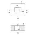
- (A) is a view in the direction of arrow X1 in FIG. 4, and
- (B) is a sectional view taken along line A2-A2 in FIG.
- FIG. 5 is a cross-sectional view showing a relationship between a hollow pavement and an upper pavement and a joint member of a lower pavement and an end lower pavement before vertical connection in the connection structure according to the first embodiment. It is sectional drawing which shows the relationship of the state which connected the hollow pavement and the upper layer pavement, the lower layer pavement, and the end lower layer pavement by the joint member in the connection structure which concerns on Embodiment 2.
- FIG. 12 is a cross-sectional view taken along the line A4-A4 of FIG.
- FIG. 5 is a plan view showing an arrangement example of a plurality of joint holes provided in the upper pavement board and the lower pavement board in the connection structure according to the second embodiment.
- FIG. (A) is a partial plan view of the upper pavement board
- (B) is a partial bottom view of the upper pavement board
- (C) is a sectional view taken along line A5-A5 of (A).
- (A) is a partial plan view of the lower pavement board
- (B) is a sectional view taken along line A6-A6 of (A).
- (A) to (F) are partial cross-sectional views showing the connection procedure of the upper pavement board and the lower pavement board in the order of the steps in the connection structure according to the second embodiment.
- the plan view of the receiving member used for the connecting structure of the upper pavement board and the lower pavement board according to the third embodiment is a sectional view taken along line A7-A7 of (A), and (C) is Y1 of (B). It is an enlarged detailed view of a part.
- the plan view of the joint member used for the connecting structure of the upper pavement board and the lower layer pavement board according to the third embodiment is a front view of the joint member, and (C) is an enlarged detail of the Y2 portion of (B). It is a figure.
- (A) to (D) are partial cross-sectional views showing the connection procedure of the upper pavement board and the lower pavement board in the order of the steps in the connection structure according to the third embodiment.
- FIG. 1 is an exploded partial perspective view for explaining the configuration of the precast paved road according to the first embodiment of the present invention, and the illustrated multi-layer precast paved road is a roadbed 6 provided on the roadbed 7.
- the illustrated multi-layer precast paved road is a roadbed 6 provided on the roadbed 7.
- It is provided with a plurality of upper layer pavement boards 2 having a rectangular plate shape, which is a pavement board made of precast to be stacked.
- the plurality of upper pavement boards 2 are arranged in a staggered pattern with respect to the plurality of lower layer pavement boards 3 and the end lower layer pavement board 4, and these upper layer pavement boards 2, the lower layer pavement board 3 and the end lower layer pavement board 2 are arranged in a staggered manner.
- the pavement board 4 is connected (fastened) in the vertical direction by a plurality of joint members 5.
- the upper pavement board 2, the lower layer pavement board 3, and the end lower layer pavement board 4 used in the present invention are formed by a known precast method in advance before the construction of the multi-layer precast pavement road of the present invention.
- the front-rear end face in the traveling direction is a tapered pavement or an auxiliary pavement formed in a substantially wedge shape at the front-rear end face.
- a board may be used.
- the joint between the rectangular plate-shaped pavement and the pavement with a tapered surface is connected with bolts or dowel pins. If there is a non-landing on the roadbed 6, loose sand is sprinkled to correct the non-landing.
- a non-landing material obtained by winding an asphalt sheet into a roll is carried in. It can be deployed and laid on the non-land portion of the roadbed 6.
- the multi-layer precast pavement road according to the present invention is based on the basic form in which the upper pavement board 2 straddles (fastens) the adjacent lower pavement boards 3 and 3 in the paved lower pavement board 3. .. Therefore, in the example shown in FIG. 1, the same number of upper pavement boards 2 are vertically connected (fastened) on each of the four lower pavement boards 3 and the end lower layer pavement board 4.
- a multi-story precast paved road with a certain width will be constructed. The width of the road changes according to the alignment, and the vehicle traffic position that becomes the trajectory does not always match the alignment of the road.
- the lower pavement board 3 and the lower end pavement board 4 are one of the upper pavement plates 2. Even if it can be laid in a straddling form, due to the difference in dimensions between the upper and lower pavement boards 2 to 4 due to changes in the road width and the vehicle traffic position that does not match the alignment, there is an odd edge on the side of the upper pavement board 2.
- the upper pavement board 2 for the half-end is adjusted, and the upper pavement board 2 can be used to adjust the half-finished pavement on the lower pavement board 3 and the lower end pavement board 4.
- "arranged in a staggered pattern” means that the lower pavement board 3 and the end portion thereof are at the joint (joint) of the lower pavement board 3 and the lower layer pavement board 4 laid in the lower layer.
- the joints (joints) between the upper pavement 2 and the lower pavement 3 and the lower end pavement 4 so that the joints (joints) of the upper pavement 2 laid on the lower pavement 4 do not overlap. It means to arrange them in a staggered manner.
- the upper pavement board 2, the lower pavement board 3, and the lower end pavement board 4 are rectangular in shape and size, but the upper layer is used. It is also possible to use pavement boards of different sizes in the lower layer. Further, in the example shown in FIG. 1, four upper pavement boards 2 are laid on the four lower pavement boards 3 and the lower end pavement board 4 laid in the road width direction. In a multi-layer precast pavement road, there are various forms in which the upper pavement 2 and the lower pavement 3 and the lower end pavement 4 are arranged so that the upper pavement 2 straddles the two lower pavements 3. There is.
- the upper pavement plate 2, the lower pavement board 3, and the lower end layer coating board 4 used for the multi-layer precast pavement road according to the present embodiment are basically rectangular or quadrangular in plan view, but the lower pavement board 3 A precast pavement board having a polygonal shape other than a rectangle or a quadrangle can be used.
- FIG. 2 is a partial cross-sectional view showing the drainage structure of the multi-layer precast paved road according to the present invention, and as shown in the figure, an upper-layer pavement board 2 composed of water-permeable concrete such as porous concrete was used as the upper layer.
- an upper-layer pavement board 2 composed of water-permeable concrete such as porous concrete was used as the upper layer.
- rainwater flows through the inside of the upper pavement 2 toward the side groove 9 on the road side as shown by the arrow X3, and the water does not permeate from the lower pavement 3 and the lower end pavement 4 to the roadbed 6 efficiently. It becomes possible to drain water to the side groove 9.
- FIG. 3 is an exploded partial perspective view for explaining the configuration of the multi-layer precast paved road according to the second embodiment of the present invention.
- the same elements as those shown in FIG. 1 are designated by the same reference numerals, and the description thereof will be omitted below.
- the precast paved road according to the second embodiment of the present invention includes a plurality of rectangular plate-shaped lower pavement boards 3 and end lower layer pavement boards 4 that are spread on the roadbed 6 provided on the roadbed 7. It is provided with a plurality of rectangular plate-shaped upper layer coating boards 2 and a hollow pavement board 1 that are stacked on the lower layer pavement board 3 and the end lower layer pavement board 4 that are spread so as to be.
- the hollow pavement board 1 is provided in place of the upper pavement board 2 located substantially in the center in the width direction on the multi-layer precast pavement road shown in FIG. 1, and penetrates the inside thereof in the road extension direction. The cavity 12 is penetrated. Since the other configuration of the multi-layer precast paved road according to the present embodiment is the same as the configuration of the multi-layer precast paved road according to the first embodiment, the description thereof will be omitted again.
- the laying position of the hollow pavement board 1 is not limited to the substantially central portion in the width direction of the road, and may be arranged, for example, on the shoulder of the road or other parts.
- the hollow pavement board 1, the upper layer pavement board 2, the lower layer pavement board 3, and the end lower layer pavement board 4 rectangular pavement boards having the same planar shape and size are used, but the upper layer and the lower layer are used. It is also possible to use pavement boards of different sizes.
- the hollow pavement board 1 one having a narrower width than that illustrated in FIG. 3 may be used.
- the hollow pavement board 1 is arranged so as to fill the space between the upper pavement boards 2 without straddling the lower pavement board 3.
- Various arrangement modes can be considered for the arrangement of the upper and lower layers of the upper pavement board 2 including the hollow pavement board 1, the lower pavement board 3 and the lower end pavement board 4.
- the hollow pavement board 1, the upper pavement board 2, the lower pavement slab 3, and the lower end pavement board 4 have a basic shape of a rectangular shape or a quadrangle in a plan view.
- a polygonal precast pavement board having a plane shape other than a rectangle or a quadrangle can be used.
- FIG. 4 is a perspective view of a hollow pavement board forming a part of the upper pavement board of the multi-layer precast pavement road according to the second embodiment of the present invention.
- the hollow pavement plate 1 illustrated in FIG. 4 has a substantially rectangular cross section in the transverse direction and is substantially rectangular in a plan view, and has a round hole-shaped joint hole 11 penetrating in the thickness direction and penetrating in the road extension direction.
- the cavity 12 is formed.
- two cavities 12 are provided in parallel in this example, and a partition wall 13 for partitioning in the road extension direction is provided between the two cavities 12.
- the plane size of the hollow pavement board 1 and the cross-sectional shape and size of the hollow 12 are not limited to those illustrated in the present embodiment.
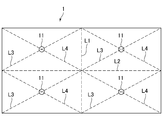
- FIG. 5 is a plan view showing an arrangement example of a plurality of (four in the illustrated example) joint holes 11 provided in the hollow pavement board 1.
- the other pavement boards (upper layer pavement board 2, lower layer pavement board 3 and end lower layer pavement board 4) also have joint holes 11 (110: see FIGS. 10 and 11) in the same arrangement pattern. It is formed.
- the joint holes 110 (see FIGS. 10 and 11) formed in the lower pavement 3 and the lower end pavement 4 do not penetrate the lower pavement 3 and the lower end pavement 4 in the vertical direction. It is preferably a specification. This is to prevent rainwater or the like from the upper pavement board 2 side including the hollow pavement board 1 from flowing into the roadbed 6 through the joint hole 110.
- the hollow pavement board 1 is provided with four joint holes 11 as an example, but when the plan view of the hollow pavement board 1 is rectangular, each joint hole 11 is provided. It is formed at the intersection of the first diagonal line L3 and the second diagonal line L4 of the four rectangles divided by the straight line L1 that bisects the rectangle to the left and right and the straight line L2 that divides the rectangle into two equal parts vertically.
- the present invention When the lower pavement 3 and the lower end pavement 4 arranged in the lower layer of the multi-layer precast pavement road and the hollow pavement 1 and the upper pavement 2 arranged in the upper layer are arranged in a staggered manner in the lower layer.
- the joint holes 110 of the lower pavement 3 and the lower end pavement 4 to be arranged and the joint holes 11 of the hollow pavement 1 and the upper pavement 2 arranged in the upper layer are arranged at corresponding coaxial positions. Therefore, the hollow pavement board 1 and the upper pavement board 2 and the lower layer pavement board 3 and the end lower layer pavement board 4 can be connected (fastened) in the vertical direction by the joint member 5.
- the position of the joint hole 11 (110) in the present embodiment may be arranged closer to the inside or outside of the pavement in consideration of the loading load and the like.
- the number of joint holes 11 (110) is not limited to four, and is 4 depending on the size of the pavement (hollow pavement 1, upper pavement 2, lower pavement 3, and lower end pavement 4). It may be more than one or less than four.
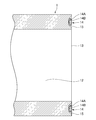
- FIG. 6 is a cross-sectional view taken along the line A1-A1 of FIG. 4, and as shown in FIG. 4, the cavity pavement board 1 shown in FIG. 4 has a groove portion 15 provided so as to orbit the end surface of the opening of the cavity 12. Is provided with a waterproof seal 14.
- the water stop seal 14 includes an expansion portion 14A and a hydrophilic portion 14B that covers the expansion portion 14A.
- urethane foam compressed in the road extension direction is used for the expansion portion 14A, but a material other than urethane foam can be used for the expansion portion 14A.
- hydrophilic portion 14B a material that expands when it comes into contact with water, such as hydrophilic urethane, is used, but if it is a material that expands when it comes into contact with water, not only hydrophilic urethane but other materials are used. You may.
- the water stop seal 14 expands in the road extension direction even if rainwater infiltrates the connecting portion, so that the rainwater infiltrates into the inside of the cavity 12. It can be prevented.
- FIG. 7 is a plan view showing another form of the hollow pavement board.
- the non-contact power feeding coil 91 is arranged on the hollow pavement board 1.
- the hollow pavement board 1 can be modularized by arranging a non-contact power feeding coil 91 inside the hollow 12.
- the adjacent non-contact power feeding coils 91 are connected to each other by an appropriate method.
- the non-contact power feeding coil 91 is not wet by rainwater or the like.
- the hollow pavement board 1 can be modularized as a pavement board with cables by arranging cables such as power lines and communication lines in the hollow 12.
- FIG. 8 (A) is a view in the direction of arrow X1 in FIG. 4
- FIG. 8 (B) is a sectional view taken along line A2-A2 in FIG. 4, and as shown in FIG. 8 (B), the hollow pavement board 1 is A tubular peripheral wall 16 forming the joint hole 11 and an arc-shaped protrusion 17 provided near the middle of the inner surface of the peripheral wall 16 in the vertical direction of the joint hole 11 are provided.
- the peripheral wall 16 is arranged inside the cavity 12, has a substantially circular shape in a plan view, and extends in the vertical direction. Further, the protrusion 17 orbits the inside of the peripheral wall 16 along the peripheral wall 16 and has a pair of notches 17A in a part in the circumferential direction.
- the hollow pavement board 1 is formed of a synthetic resin that exhibits sufficient molding strength as a road.
- this synthetic resin include FRP and various high-strength plastics (PAI, PEEK, etc.), and in addition to synthetic resin, carbon fiber reinforced concrete and FRP reinforced concrete can also be used.
- PAI high-strength plastics
- carbon fiber reinforced concrete and FRP reinforced concrete can also be used.
- the upper pavement board 2 and the lower pavement board 3 in the present invention are made of precast concrete in which the cross section of the hollow pavement board 1 without the cavity 12 is enriched and the joint hole 110 similar to the joint hole 11 is provided. It has the same shape as the outer shape of the hollow pavement board 1. Therefore, the joint hole 110 also includes an arcuate protrusion 170 and a pair of notches 170A.
- the lower end pavement board 4 has a form in which the lower pavement board 3 is divided into two equal parts vertically in a plan view, but the plan shape of the lower end pavement board 4 is not limited to this example.
- the lower pavement board 3 and the lower end pavement board 4 are provided with a seal made of a water-swellable resin such as hydrophilic polyurethane so as to face each other on the side surfaces that come into contact with each other when they are laid. It is desirable to have.
- the upper pavement board 2 may be made of porous concrete that allows water to pass through, a porous structure that can reduce running noise, or a structure that has slits on the surface.
- the lower pavement board 3 and the end lower layer pavement board 4 can be formed by using reinforced concrete, steel fiber reinforced concrete, or fiber reinforced concrete. Reinforced concrete, steel fiber reinforced concrete, or fiber reinforced concrete can also be used for the upper pavement board 2.
- the multi-layer precast pavement road according to the present invention can have strength and durability as a pavement road.
- the present invention is applied to a bridge, the upper pavement board 2 including the hollow pavement board 1 is directly connected to the lower layer pavement board 3 in which the floor board constructed on the girder is spread.
- the lower pavement board 3 including the lower end pavement board 4 can be omitted.
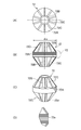
- FIG. 9 is a perspective view showing an example of the joint member 5, wherein the illustrated joint member 5 has a substantially cylindrical main body 51 and a cylindrical base 52 arranged at the upper end of the main body 51. It includes an umbrella-shaped variable lock portion 53, a leg portion 55 extending downward, and a pair of substantially convex flange portions 56 that are integrally projected so as to face each other in the circumferential direction of the leg portion 55.
- the diameter of the base portion 52 is set to be smaller than the diameter of the main body portion 51, and the diameter of the lower end of the variable lock portion 53 is set to be larger than the diameter of the base portion 52 and smaller than the diameter of the main body portion 51.
- the diameter of the cage is gradually decreasing upward.
- the variable lock portion 53 is formed with four slit-shaped notched groove portions 54 cut out from the upper end portion to the middle of the base portion 52 at an equal angle pitch (90 ° pitch) in the circumferential direction. That is, the slit-shaped notch groove portion 54 formed long in the vertical direction is formed so as to divide the substantially umbrella-shaped variable lock portion 53 and the base portion 52 into four in the circumferential direction.
- the leg portion 55 has a diameter smaller than the diameter of the main body portion 51 and extends downward.
- the pair of flange portions 56 integrally formed so as to face each other in the circumferential direction of the leg portions 55 have the same diameter (circumscribed circle diameter) as the diameter of the main body portion 51, and the joint hole 110 (11). It has a planar shape capable of passing through the notch 170A (17A) of the protrusion 170 (17) in the above.
- the distance between the lower end surface of the main body 51 and the upper end surface of the flange 56 (the apparent length of the legs 55) is set to be slightly larger than the thickness of the protrusion 170 (17).
- the joint member 5 is detachably installed in the four joint holes 110 formed in the lower pavement board 3 and the lower end pavement board 4, and the four joints formed in the hollow pavement board 1 and the upper pavement board 2 are formed.
- a substantially umbrella-shaped variable lock portion 53 controls mounting allowance and removal regulation of the hollow pavement board 1 or the upper pavement board 2.
- the variable lock portion 53 is not limited to a substantially umbrella-shaped shape. For example, if the cross-sectional shape of the inner circumference of the protrusion 17 is an inverted taper, the variable lock portion 53 is not substantially an umbrella shape, but a substantially columnar shape having a notch groove portion 54 is sufficient.
- the joint member 5 can be made of plastic, metal, or a composite material thereof.
- FIG. 10 is a cross-sectional view showing the relationship between the hollow pavement 1 and the upper pavement 2 and the lower pavement 3 and the joint member 5 before the upper and lower connection of the lower end pavement 4, and FIG. 11 shows the hollow pavement 1 and the upper pavement. It is sectional drawing which shows the relationship of the state which the board 2, the lower layer pavement board 3 and the end lower layer pavement board 4 are connected (fastened) by a joint member 5.
- a pair of flange portions 56 below the joint member 5 pass through a notch 170A formed in a protrusion 170 of the joint hole 110 of the lower layer pavement board 3 and the end lower layer pavement board 4. Then, it is inserted into the back of the protrusion 170, and then rotated by, for example, an angle of 90 ° around the axis, so that the flange 56 engages with the protrusion 170 of the lower pavement 3 and the lower end pavement 4. It will not come out in either the upward or downward direction.
- the hollow pavement board 1 or the upper layer pavement board 2 is placed from above so that the joint member 5 fits into the joint hole 11 formed therein. Then, since the joint member 5 includes a substantially umbrella-shaped variable lock portion 53 having a notch groove portion 54, when the notch groove portion 54 of the variable lock portion 53 is compressed by the protrusion portion 17, it has a substantially umbrella shape.
- the variable lock portion 53 of the above enters between the protrusions 17 and opens when the lower end portion 53A of the variable lock portion 53 passes through the protrusion 17.
- the hollow pavement 1 or the upper pavement 2 fitted in the joint member 5 faces upward. I can't get out of it.
- the upper pavement board 2 including the hollow pavement board 1 is tightly coupled to the lower pavement board 3 including the lower end pavement board 4 via the joint member 5 to form two upper and lower layers (hollow pavement board 1). 2) and the lower pavement board (including the lower end pavement board 4) 3 are combined and integrated.
- the joint member 5 used in the multi-layer precast paved road according to the present invention is not limited to the one used in the present embodiment.
- the leg portion 55 formed at the lower part of the joint member 5 and the substantially convex shape provided on the periphery thereof instead of the substantially umbrella-shaped variable lock portion 53 provided on the joint member 5, the leg portion 55 formed at the lower part of the joint member 5 and the substantially convex shape provided on the periphery thereof.
- a joint member in which the flange portion 56 is provided on the upper portion of the main body portion 51 in a vertically symmetrical direction can be used.
- the joint member may be provided with a jig hole such as a through hole on the central axis thereof, and the jig hole may be used to hold a jig for rotating the joint member.
- the variable lock portion can be considered to be one that is deformed to perform the locking function and one that is displaced to perform the locking function.
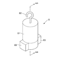
- FIG. 12 is a perspective view showing an example of the removing tool 8 of the joint member 5, and FIG. 13 is a sectional view taken along line A4-A4 of FIG.
- the remover 8 faces a pressing portion 81 having a hollow portion 84 (see FIG. 13) whose diameter gradually increases downward on the lower end surface and facing the lower end portion of the pressing portion 81.
- a pair of hooking protrusions 83 and a hook 82 provided at the upper end of the pressing portion 81 are provided.
- the maximum diameter of the hollow portion 84 of the removal jig 8 is the same as or slightly smaller than the maximum diameter of the substantially umbrella-shaped variable lock portion 53.
- the vertical length of the hollow portion 84 is the same as or slightly longer than the vertical length of the substantially umbrella-shaped variable lock portion 53, and as shown in FIG. 13, the hollow portion 84 is convex inward in the vertical cross section. It has a curved surface that becomes.
- the length from one end to the other end of the hooking protrusion 83 is substantially equal to the diameter of the joint hole 11. Further, the outer diameter of the pressing portion 81 is slightly smaller than the diameter of the circumscribed circle of the protruding portion 17.
- the remover 8 is pressed from above so that the substantially umbrella-shaped variable lock portion 53 fits into the hollow portion 84.
- the substantially umbrella-shaped variable lock portion 53 has a notch groove portion 54
- the variable lock portion 53 is pushed by the cavity portion 84 and the notch groove portion 54 contracts in the radial direction, so that the lower end of the substantially umbrella-shaped variable lock portion 53 is formed.
- the engagement between the portion 53A and the protrusion 17 is released.
- the hooking protrusion 83 is further pushed downward in a direction that does not interfere with the protrusion 17, and when the hooking protrusion 83 exceeds the protrusion 17, the remover 8 is rotated. The portion 83 engages with the protrusion 17. Then, from this state, when the remover 8 is pulled upward by a wire or the like hooked on the hook 82, the hollow pavement board 1 or the upper pavement board 2 can be removed from the joint member 5. This work can be performed in the four joint holes 11 of the hollow pavement 1 or the upper pavement 2 to separate the hollow pavement 1 or the upper pavement 2 from the lower pavement 3 including the lower end pavement 4. it can.
- FIG. 14 is a plan view showing an arrangement example of a plurality of joint holes provided in the upper pavement board and the lower pavement board in the connection structure according to the second embodiment
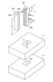
- FIG. 15 is an exploded portion showing the connection structure according to the second embodiment.
- a perspective view FIG. 14 (A) is a partial plan view of the upper pavement board
- FIG. 14 (B) is a partial bottom view of the upper pavement board
- FIG. 14 (C) is a sectional view taken along line A5-A5 of FIG. 14 (A).
- 15 (A) is a partial plan view of the lower pavement board
- FIG. 15 (B) is a sectional view taken along line A6-A6 of FIG. 15 (A)
- FIGS. 16 (A) to 16 (F) relate to the second embodiment.
- It is a partial cross-sectional view which shows the connection procedure of the upper layer pavement and the lower layer pavement in the order of the process in the connection structure.
- joints having a rectangular shape in a plan view are provided at four locations (the same locations as in the first embodiment (see FIG. 5)) of the upper pavement board 2 and the lower pavement board 3.
- Holes 11 and 110 are penetrated in the vertical direction (see FIGS. 15 and 17 for the joint hole 110 formed in the lower pavement board 3).
- the structure around the joint holes 11 and 110 at one location will be illustrated and described, but since the structures around the joint holes 11 and 110 at other locations are the same, the illustration and description thereof will be described. Omit.
- a rectangular block-shaped engaging convex is formed on the lower half of the short side surface (right end surface of FIG. 16).
- the portions 61 are integrally formed.
- a rectangular engagement in a plan view extending in the longitudinal direction of the joint hole 11 (left side in FIG. 16) from the surface on the short side facing the engaging convex portion 61 of the joint hole 11.
- a recess 62 is formed.
- the resin joint member 64 and the wedge member 65 shown in FIG. 15 are used for connecting the upper pavement board 2 and the lower pavement board 3.
- the joint member 64 includes a square columnar main body portion 64A and rectangular block-shaped engaging protrusions 64B and 64C protruding horizontally and integrally in the same direction from the upper and lower ends of the same surface of the main body portion 64.
- Two slit-shaped fitting grooves 64a are formed in the vertical direction at appropriate intervals in the width direction on the surface of the main body 64A opposite to the side on which the engaging convex portion 64A is formed. ..
- the wedge member 65 includes a rectangular flat plate-shaped main body portion 65A that is long in the vertical direction, and two rectangular rib-shaped fitting protrusions that are long in the vertical direction from one end surface on the long side side of the main body portion 64A. 65a is projected integrally.
- the two fitting protrusions 65a are fitted into the two fitting grooves 64a formed in the joint member 64 as described later, and have the same pitch as the seven fitting grooves 64a in the width direction. Have been placed.
- the hanging tool 100 whose tip is bent in an L shape is inserted into the joint hole 11 of the upper pavement board 2 from above, and the tip is engaged with the upper pavement board 2. Engage with the joint recess 62. Then, in that state, the hanging tool 100 is pulled up and the upper pavement board 2 is hung horizontally. Then, the upper pavement board 2 was moved onto the lower pavement board 3 laid in advance, and the joint hole 11 formed in the upper pavement board 2 was positioned so as to match the joint hole 110 formed in the lower pavement board 3. In this state, the upper pavement board 2 is lowered, and as shown in FIG. 18B, the upper pavement board 2 is superposed on the lower pavement board 3.
- the height dimensions h1, h2, h3 of each part shown in FIG. 18B substantially match the height dimensions h1, h2, h3 of each part of the joint member 64 shown in FIG. 15, and the upper pavement board 2 and the lower layer pavement board 3
- the total height H of the joint member 64 and the wedge member 65 substantially coincide with the height H of the joint member 64 and the wedge member 65.
- the upper pavement board 2 is superposed on the lower pavement board 3, and the joint holes 11 and 110 formed in both are matched with each other, and is shown in FIG. 18 (C).
- the joint member 64 is inserted into the joint holes 11 and 110 formed in the upper pavement board 2 and the lower pavement board 3 from above and passed through.
- the engaging protrusions 64B and 64C projecting above and below the joint member 64 do not interfere with the engaging protrusions 61 and 62 projecting from the upper pavement board 2 and the lower pavement board 3, respectively. It can pass through the joint holes 11, 110.
- the joint member 64 When the joint member 64 is passed through the joint holes 11 and 110 formed in the upper pavement board 2 and the lower pavement board 3 as described above, the joint member 64 is moved in the direction of the arrow as shown in FIG. 18 (D).
- the engaging protrusions 64B and 64C projecting above and below the connecting member 64 are engaged with the engaging protrusions 61 and 62 projecting from the upper pavement board 2 and the lower pavement board 3, respectively. ..
- the joint is formed as shown in FIG. 18 (E). Since a gap is formed between the member 64 and the joint holes 11 and 110, the wedge member 65 is inserted into this gap from above. At this time, the two fitting protrusions 65a projecting from the wedge member 65 are fitted into the two fitting grooves 64a formed in the joint member 64, and the wedge member 65 is moved downward while maintaining this state. Type in.
- the inside of the joint holes 11 and 110 of the joint member 64 is as shown in FIG.
- the upper and lower engaging protrusions 64B and 64C of the joint member 64 are securely engaged with the engaging protrusions 61 and 62 of the upper pavement board 2 and the lower pavement board 3 because the movement is prevented and fixed. Therefore, the upper pavement board 2 and the lower pavement board 3 are securely connected by the joint member 64.
- 19 (A) is a plan view of a receiving member used for the connecting structure of the upper pavement board and the lower pavement board according to the third embodiment
- 19 (B) is a sectional view taken along line A7-A7 of FIG. 19 (A).
- 19 (C) is a perspective view of the receiving member
- FIG. 17 (D) is an enlarged detailed view of the Y1 portion of FIG. 17 (B)
- FIG. 20 (A) is an upper pavement and a lower pavement according to the third embodiment.
- a plan view of the joint member used for the connecting structure with the panel FIG. 20 (B) is a front view of the joint member
- FIG. 20 (C) is a perspective view of the same piece member
- FIG. 20 (D) is FIG. 20 (B).
- 21 (A) to (F) which are enlarged detailed views of the Y2 portion of (1), are partial cross-sectional views showing the procedure for connecting the upper pavement and the lower pavement in the order of the steps in the connection structure according to the third embodiment.
- the upper pavement board 2 and the lower pavement board 3 are connected at four places similar to those shown in FIGS. 5 and 14, but the connecting structure of only one place will be described below. To do.
- the receiving member 71 shown in FIG. 19 and the joint member 72 shown in FIG. 20 are used.
- the receiving member 71 and the joint member 72 are both integrally molded of resin.
- the receiving member 71 is formed in a cup shape, and extends from the circular bottom surface portion 71A and the bottom surface portion 71A while increasing the diameter toward the upper side of FIG. 19 (B). It includes a tapered cylindrical side surface portion 71B and a low-height cylindrical portion 71C that rises in parallel from the side surface portion 71B to form an opening peripheral edge of the receiving member 71.
- a plurality of protrusions 71a having a chevron-shaped cross section are formed on the inner circumference of the cylindrical portion 71C of the receiving member 71 over the entire circumference.
- the joint member 72 includes a disc portion 72A and a cylindrical portion 72B extending vertically from the center of the upper and lower surfaces of the disc portion 72A, and the disc portion 72A and the upper and lower cylindrical portions.
- the 72B is connected to each other by a plurality of triangular reinforcing ribs 72C (10 in the illustrated example).
- the plurality of (10) reinforcing ribs 72C are radially arranged at an equal angle pitch (36 ° pitch) in the circumferential direction.
- the outer diameter ⁇ D of the disk portion 72A of the joint member 72 is set to be slightly smaller than the inner diameter ⁇ d of the cylindrical portion 71C of the receiving member 71 ( ⁇ D ⁇ d).
- a plurality of protrusions 72a having a chevron-shaped cross section are formed on the outer circumference of the disk portion 72A over the entire circumference.
- the receiving member 71 is embedded and fixed in advance on the upper surface of the lower pavement board 3, and the lower half of the joint member 72 is fitted into the receiving member 71 from above. Both are combined as shown in 21 (B).
- a plurality of protrusions 71a are formed on the inner peripheral surface of the cylindrical portion 71C of the receiving member 71 over the entire circumference, and a plurality of similar protrusions 72a are also formed on the outer circumference of the disc portion 72A of the joint member 72. Since these protrusions 71a and 72a are fitted to each other, the joint member 72 can be prevented from coming off from the receiving member 71. In this state, the joint member 72 is connected to and fixed to the receiving member 71 with its upper half protruding upward from the upper surface of the lower pavement board 3.
- the upper pavement board 2 to which the other receiving member 71 is pre-embedded and fixed with the opening facing down is positioned and lowered toward the lower pavement board 3. ..
- the upper pavement board 2 is superposed on the lower pavement board 3, and one receiving member 71, which is received and fixed by the upper pavement board 2, is a joint member. Since it is fitted into the upper half of 72, the upper pavement board 2 and the lower pavement board 3 are connected to each other by the joint member 72.
- a plurality of protrusions 71a see FIG.
- the multi-layer precast pavement road includes a plurality of precast lower-layer pavement 2 (including the hollow pavement 1) laid on the roadbed 6 and the lower-layer pavement.
- a plurality of precast upper-layer pavement boards 3 (including end lower-layer pavement boards 4) laid on the upper surface of the board 2 are provided, and the lower-layer pavement board 3 and the upper-layer pavement board 2 are staggered.
- a joint member 5 (64, 72) is provided so as to straddle the upper and lower joint surfaces of the lower pavement board 3 and the upper pavement board 2, and the lower pavement of the joint member 5 (64, 72) is provided. Since the lower pavement board 3 and the upper pavement board 2 are connected and configured by engaging or fitting the board 3 with the upper pavement board 2, the following effects are obtained.
- the multi-layer precast pavement road according to the present invention is the same as the precast multi-layer upper pavement 2 (including the hollow pavement 1) and the precast lower pavement 3 (including the end lower layer pavement 4).
- the two-dimensionally adjacent objects are not directly connected to each other, and the plurality of upper pavement boards 2 (hollow pavement board 1) and the plurality of lower layer pavement boards 3 (end lower layer pavement board 4) constituting the upper and lower layers are connected. Since the structure is such that three-dimensionally contacted objects are connected to each other by joint members 5 (64, 72) at a plurality of points, even if the roadbed 6 or the roadbed 7 supporting the pavement is deformed. ,
- the upper pavement plate 2 (hollow pavement 1) straddling the joint portion eases the bending of the joint portion between the lower layer pavement 3 (end lower layer pavement 4), and a step is generated in the multi-layer precast pavement road. Absent.
- the upper pavement 2 (hollow pavement 1) and the lower pavement 3 (end lower pavement 4) are both precast and have a two-layer upper and lower structure, new construction is also repaired. It can be easily carried out without being affected by the weather or causing noise problems, and it is possible to provide a multi-layer precast paved road having excellent durability.
- both the upper pavement 2 (hollow pavement 1) and the lower pavement 3 (lower end pavement 4) are made of precast, the pavements 1 to 4 used for construction are planned in advance at the factory. It can be manufactured and stocked, and even if urgent repair work is required, it will be possible to respond easily and promptly.
- the construction is a construction form in which the pavement boards 1 to 4 of each layer are lifted one by one by a crane and laid on the roadbed 6, the heavy machinery dedicated to pavement and the pavement technology that have been used in the past are acquired. Construction is possible without a skilled engineer.
- the repair can be completed by removing and replacing the paved board of the damaged part, so that the repair work can be carried out in a short time with low noise. It is possible.
- the upper pavement 2 (hollow pavement 1) is arranged in a staggered pattern with respect to the lower pavement 3 (end lower pavement 4) laid on the roadbed 6. Since these are connected by the joint member 5 (64, 72), no step is generated.
- a pavement board having various functions as the upper pavement board 2 for example, rainwater can be efficiently drained, a coil for non-contact power feeding can be provided, and chargeability and banding can be achieved. It is possible to improve the magnetism, and it is possible to easily construct a paved road having functions not found in conventional paved roads.
- joint member 5 (64, 72) is made of plastic, a plastic composite material, or the like, these will not rust and their durability will be enhanced. Then, by using the joint member 5 (64, 72) for connecting the upper pavement 2 (hollow pavement 1) and the lower pavement 3 (end lower pavement 4), these joint members 5 (64, 72) does not loosen during use like bolts and nuts, and the upper pavement (hollow pavement 1) can be easily attached to and detached from the lower pavement 3 (end lower pavement 4).
Landscapes
- Engineering & Computer Science (AREA)
- Architecture (AREA)
- Civil Engineering (AREA)
- Structural Engineering (AREA)
- Road Paving Structures (AREA)
Abstract
Description
[複層プレキャスト舗装道路]
<実施の形態1>
図1は本発明の実施の形態1に係るプレキャスト舗装道路の構成を説明するための分解部分斜視図であり、図示の複層プレキャスト舗装道路は、路床7の上に設けられた路盤6の上に敷き詰められるプレキャスト製の舗装盤である矩形プレート状の複数の下層舗装盤3及び端部下層舗装盤4と、このように敷き詰められた下層舗装盤3と端部下層舗装盤4の上に重ねられるプレキャスト製の舗装盤である矩形プレート状の複数の上層舗装盤2を備えている。ここで、複数の上層舗装盤2は、複数の下層舗装盤3及び端部下層舗装盤4に対して千鳥状に配置されており、これらの上層舗装盤2と下層舗装盤3及び端部下層舗装盤4とは、複数の継手部材5によって上下方向に連結(締結)されている。
ここで、複層プレキャスト舗装道路の排水構造の一例を図2に基づいて以下に説明する。
次に、本発明に係る複層プレキャスト舗装道路の実施の形態2を図3に基づいて以下に説明する。
ここで、空洞舗装盤1の構成を図4に基づいて以下に説明する。
ここで、空洞舗装盤の他の形態を図7に基づいて以下に説明する。
<連結構造の実施の形態1>
図8(A)は図4の矢視X1方向の図、図8(B)は図4のA2-A2線断面図であり、図8(B)に示すように、空洞舗装盤1は、継手孔11を形成する筒状の周壁16と、継手孔11の上下方向における周壁16の内面の中間付近に設けられた円弧状の突起部17を備えている。
次に、上層舗装盤2と下層舗装盤3との連結構造の実施の形態2を図14~図18に基づいて以下に説明する。
次に、空洞舗装盤1を含む上層舗装盤2と端部下層舗装盤4を含む下層舗装盤3との連結構造の実施の形態3を図19~図21に基づいて以下に説明する。
以上の説明で明らかなように、本発明に係る複層プレキャスト舗装道路は、路盤6の上に敷設されたプレキャスト製の複数の下層舗装盤2(空洞舗装盤1を含む)と、該下層舗装盤2の上面に敷設されたプレキャスト製の複数の上層舗装盤3(端部下層舗装盤4を含む)と、を備えるものであって、前記下層舗装盤3と前記上層舗装盤2とを千鳥状に配置するとともに、前記下層舗装盤3と前記上層舗装盤2の上下接合面に跨って介在する継手部材5(64,72)を設け、該継手部材5(64,72)の前記下層舗装盤3と前記上層舗装盤2との係合または嵌合によってこれらの下層舗装盤3と上層舗装盤2とを連結して構成されるため、以下の効果を奏する。
2 上層舗装盤
3 下層舗装盤
4 端部下層舗装盤
5 継手部材
6 路盤
7 路床
8 取外し具
9 側溝
11,110 継手孔
12 空洞
13 仕切壁
14 止水シール
14A 膨脹部
14B 親水部
15 溝部
16 側壁
17,170 突起部
51 本体部
52 基部
53 略傘状の可変ロック部
54 溝部
55 脚部
56 フランジ部
61,63 係合凸部
64 継手部材
65 楔部材
71 受け部材
72 継手部材
81 押圧部
82 フック
83 引掛け突起部
84 空洞部
91 非接触給電用コイル
Claims (9)
- 路盤の上に敷設されたプレキャスト製の複数の下層舗装盤と、該下層舗装盤の上面に敷設されたプレキャスト製の複数の上層舗装盤と、を備える複層プレキャスト舗装道路であって、
前記下層舗装盤と前記上層舗装盤とを千鳥状に配置するとともに、
前記下層舗装盤と前記上層舗装盤の上下接合面に跨って介在する継手部材を設け、該継手部材の前記下層舗装盤と前記上層舗装盤との係合または嵌合によってこれらの下層舗装盤と上層舗装盤とを連結して構成されることを特徴とする複層プレキャスト舗装道路。 - 前記下層舗装盤の下面と前記上層舗装盤の上面にカップ状の受け部材をそれぞれ埋め込んで固定し、両受け部材に前記継手部材の上半部と下半部を前記受け部材にそれぞれ嵌合させることによって、前記下層舗装盤と前記上層舗装盤とを連結することを特徴とする請求項1に記載の複層プレキャスト舗装道路。
- 前記下層舗装盤と前記上層舗装盤に互いに連通する継手孔をそれぞれ形成し、両継手孔に挿通する前記継手部材の上端部と下端部を前記下層舗装盤と前記上層舗装盤にそれぞれ係合させることによって、前記下層舗装盤と前記上層舗装盤とを連結することを特徴とする請求項1に記載の複層プレキャスト舗装道路。
- 前記継手部材の上端部に略傘状の可変ロック部を形成し、前記下層舗装盤に形成された前記継手孔に挿通して該下層舗装盤の上面から上方へ突出する前記継手部材の前記可変ロック部を前記上層舗装盤の係合部に係合させることによって、前記下層舗装盤と前記上層舗装盤とを連結することを特徴とする請求項3に記載の複層プレキャスト舗装道路。
- 前記継手部材を、これの上下端部にそれぞれ形成された係合突起と前記各継手孔にそれぞれ突設された係合凸部との干渉を避けながら両継手孔に通した後、該継手部材を移動させて前記係合突起を前記係合凸部に係合させ、前記継手孔と前記継手部材との間に形成される隙間に楔部材を打ち込むことによって、前記下層舗装盤と前記上層舗装盤とを連結することを特徴とする請求項3に記載の複層プレキャスト舗装道路。
- 前記上層舗装盤の一部は、
道路伸延方向に貫通する空洞を有し、前記空洞の開口部を周回するように止水シールを備えた空洞舗装盤で構成されることを特徴とする請求項1~5の何れかに記載の複層プレキャスト舗装道路。 - 前記空洞舗装盤は、プラスチック、炭素繊維補強コンクリート、FRP鉄筋コンクリートの何れかによって構成され、前記空洞の内部に配置される非接触給電用コイルを備えることを特徴とする請求項6に記載の複層プレキャスト舗装道路。
- 前記上層舗装盤は、透水性の素材、又はポーラス構造かスリット表面の走行音低減性の素材によって構成されることを特徴とする請求項1~7の何れかに記載の複層プレキャスト舗装道路。
- 前記下層舗装盤は、隣接する前記下層舗装盤と対向する側面に止水シールを有することを特徴とする請求項1~8の何れかに記載の複層プレキャスト舗装道路。
Priority Applications (4)
| Application Number | Priority Date | Filing Date | Title |
|---|---|---|---|
| EP20776392.1A EP3922771A4 (en) | 2019-03-28 | 2020-01-08 | MULTI-LAYER PREFABRICATED ROAD |
| CA3132794A CA3132794C (en) | 2019-03-28 | 2020-01-08 | Multilayer precast paved road |
| US17/429,684 US12392093B2 (en) | 2019-03-28 | 2020-01-08 | Multilayer precast paved road |
| JP2020500908A JP7396978B2 (ja) | 2019-03-28 | 2020-01-08 | 複層プレキャスト舗装道路 |
Applications Claiming Priority (2)
| Application Number | Priority Date | Filing Date | Title |
|---|---|---|---|
| JP2019063082 | 2019-03-28 | ||
| JP2019-063082 | 2019-03-28 |
Publications (1)
| Publication Number | Publication Date |
|---|---|
| WO2020194987A1 true WO2020194987A1 (ja) | 2020-10-01 |
Family
ID=72610880
Family Applications (1)
| Application Number | Title | Priority Date | Filing Date |
|---|---|---|---|
| PCT/JP2020/000261 Ceased WO2020194987A1 (ja) | 2019-03-28 | 2020-01-08 | 複層プレキャスト舗装道路 |
Country Status (4)
| Country | Link |
|---|---|
| US (1) | US12392093B2 (ja) |
| EP (1) | EP3922771A4 (ja) |
| JP (1) | JP7396978B2 (ja) |
| WO (1) | WO2020194987A1 (ja) |
Cited By (3)
| Publication number | Priority date | Publication date | Assignee | Title |
|---|---|---|---|---|
| CN115058933A (zh) * | 2022-05-20 | 2022-09-16 | 安徽久传建筑工程有限公司 | 一种市政道路铺设结构 |
| JP2023022886A (ja) * | 2021-08-04 | 2023-02-16 | フジミ工研株式会社 | Pca部材を用いた橋梁用伸縮装置及びその施工方法 |
| JP2023166787A (ja) * | 2022-05-10 | 2023-11-22 | 株式会社大林組 | 給電装置の埋設構造及び給電装置の埋設方法 |
Families Citing this family (1)
| Publication number | Priority date | Publication date | Assignee | Title |
|---|---|---|---|---|
| WO2021187862A1 (ko) * | 2020-03-16 | 2021-09-23 | 엘지전자 주식회사 | 무선 통신 시스템에서 공간 파라미터 기반 신호 송수신 방법 및 장치 |
Citations (7)
| Publication number | Priority date | Publication date | Assignee | Title |
|---|---|---|---|---|
| JPS637402A (ja) * | 1986-06-27 | 1988-01-13 | 大高 英昭 | 敷設ブロツク |
| JPH0288804A (ja) * | 1988-09-24 | 1990-03-29 | Nishiki Kogyo Kk | ロードヒーティングの施工方法 |
| JPH0653606U (ja) * | 1992-12-17 | 1994-07-22 | 株式会社イノアックコーポレーション | 弾性舗装材 |
| JPH07324302A (ja) * | 1994-06-01 | 1995-12-12 | Yamau:Kk | 透水性ゴム舗装コンクリート板 |
| JPH08326007A (ja) | 1995-05-31 | 1996-12-10 | Fukudagumi:Kk | 仮設道路 |
| JPH09316805A (ja) * | 1996-05-28 | 1997-12-09 | Hiroshi Igarashi | ブロックとブロックアレイ |
| JPH10325102A (ja) * | 1997-05-27 | 1998-12-08 | Inax Corp | 舗装構造 |
Family Cites Families (23)
| Publication number | Priority date | Publication date | Assignee | Title |
|---|---|---|---|---|
| US340153A (en) * | 1886-04-20 | Aethue pimm | ||
| US1411415A (en) * | 1920-12-11 | 1922-04-04 | Ralph M Cooley | Pavement |
| FR584067A (ja) | 1923-07-03 | 1925-01-29 | ||
| US2282335A (en) * | 1933-05-10 | 1942-05-12 | Clyde L Methven | Expansion joint construction |
| US2700329A (en) * | 1946-05-18 | 1955-01-25 | John E Carter | Elastomeric strip for vertical pavement joints |
| US2508443A (en) * | 1946-08-20 | 1950-05-23 | John E Carter | Sealed joint for concrete slab road pavements |
| US4488833A (en) * | 1982-04-27 | 1984-12-18 | Kaiser Aluminum & Chemical Corporation | Rapidly deployed assault vehicle surfacing or trackway system |
| US4522531A (en) * | 1983-05-18 | 1985-06-11 | Thomsen Bernard D | Transverse joint cell for concrete structures |
| US5664899A (en) * | 1991-07-22 | 1997-09-09 | Eustis; Robert H. | Furniture joint |
| US5816738A (en) * | 1996-10-03 | 1998-10-06 | Abo System-Elemente Gmbh | Composite synthetic material tile and suitable laying system and laying plate therefor |
| AT407777B (de) * | 1999-04-26 | 2001-06-25 | Blum Gmbh Julius | Verbindungsbeschlag zum lösbaren verbinden zweier möbelteile |
| GB2375131A (en) * | 2001-04-24 | 2002-11-06 | Anthony Crabbe | Ground cover panel |
| US7314333B2 (en) * | 2003-08-13 | 2008-01-01 | Shaw & Sons, Inc. | Plate concrete dowel system |
| KR20090001058U (ko) * | 2007-07-26 | 2009-02-02 | 배석호 | 석재 판넬 |
| US9546044B2 (en) * | 2008-02-06 | 2017-01-17 | Oldcastle Precast, Inc. | Method and apparatus for capturing, storing, and distributing storm water |
| KR20130050445A (ko) * | 2011-11-08 | 2013-05-16 | 태양 박 | 조립식 도로 |
| US20130326966A1 (en) * | 2012-06-12 | 2013-12-12 | The Spancrete Group, Inc. | Precast pervious concrete panels |
| US9206596B1 (en) * | 2015-03-10 | 2015-12-08 | Schul International, Inc. | Expansion joint seal system |
| US20160355997A1 (en) * | 2015-06-04 | 2016-12-08 | James Curtis Lewley | Method of retrofitting a ground surface to resist snow and ice |
| JP6834877B2 (ja) * | 2017-09-20 | 2021-02-24 | トヨタ自動車株式会社 | 非接触給電システム及び受電側装置 |
| DE202018004468U1 (de) * | 2018-09-25 | 2018-10-29 | Peter Nägele | Zerlegbare Bodenplatte |
| US10794055B1 (en) * | 2019-04-09 | 2020-10-06 | Schul International Company, LLC | Composite joint seal |
| US11766947B2 (en) * | 2021-05-28 | 2023-09-26 | Zoox, Inc. | DC fast charger wireless-charging adapter |
-
2020
- 2020-01-08 JP JP2020500908A patent/JP7396978B2/ja active Active
- 2020-01-08 EP EP20776392.1A patent/EP3922771A4/en active Pending
- 2020-01-08 US US17/429,684 patent/US12392093B2/en active Active
- 2020-01-08 WO PCT/JP2020/000261 patent/WO2020194987A1/ja not_active Ceased
Patent Citations (7)
| Publication number | Priority date | Publication date | Assignee | Title |
|---|---|---|---|---|
| JPS637402A (ja) * | 1986-06-27 | 1988-01-13 | 大高 英昭 | 敷設ブロツク |
| JPH0288804A (ja) * | 1988-09-24 | 1990-03-29 | Nishiki Kogyo Kk | ロードヒーティングの施工方法 |
| JPH0653606U (ja) * | 1992-12-17 | 1994-07-22 | 株式会社イノアックコーポレーション | 弾性舗装材 |
| JPH07324302A (ja) * | 1994-06-01 | 1995-12-12 | Yamau:Kk | 透水性ゴム舗装コンクリート板 |
| JPH08326007A (ja) | 1995-05-31 | 1996-12-10 | Fukudagumi:Kk | 仮設道路 |
| JPH09316805A (ja) * | 1996-05-28 | 1997-12-09 | Hiroshi Igarashi | ブロックとブロックアレイ |
| JPH10325102A (ja) * | 1997-05-27 | 1998-12-08 | Inax Corp | 舗装構造 |
Cited By (6)
| Publication number | Priority date | Publication date | Assignee | Title |
|---|---|---|---|---|
| JP2023022886A (ja) * | 2021-08-04 | 2023-02-16 | フジミ工研株式会社 | Pca部材を用いた橋梁用伸縮装置及びその施工方法 |
| JP7718898B2 (ja) | 2021-08-04 | 2025-08-05 | フジミ工研株式会社 | Pca部材を用いた橋梁用伸縮装置及びその施工方法 |
| JP2023166787A (ja) * | 2022-05-10 | 2023-11-22 | 株式会社大林組 | 給電装置の埋設構造及び給電装置の埋設方法 |
| JP7815981B2 (ja) | 2022-05-10 | 2026-02-18 | 株式会社大林組 | 給電装置の埋設構造及び給電装置の埋設方法 |
| CN115058933A (zh) * | 2022-05-20 | 2022-09-16 | 安徽久传建筑工程有限公司 | 一种市政道路铺设结构 |
| CN115058933B (zh) * | 2022-05-20 | 2023-11-03 | 安徽久传建筑工程有限公司 | 一种市政道路铺设结构 |
Also Published As
| Publication number | Publication date |
|---|---|
| EP3922771A1 (en) | 2021-12-15 |
| US12392093B2 (en) | 2025-08-19 |
| JP7396978B2 (ja) | 2023-12-12 |
| CA3132794A1 (en) | 2020-10-01 |
| US20220205187A1 (en) | 2022-06-30 |
| EP3922771A4 (en) | 2022-11-09 |
| JPWO2020194987A1 (ja) | 2020-10-01 |
Similar Documents
| Publication | Publication Date | Title |
|---|---|---|
| WO2020194987A1 (ja) | 複層プレキャスト舗装道路 | |
| JP2016037746A (ja) | 道路橋の埋設継手構造とその施工法 | |
| JP6097965B2 (ja) | 橋梁用コンクリートプレキャスト床版の施工方法 | |
| US20170022726A1 (en) | Prefabricated, deconstructable, multistory building construction | |
| KR20110132909A (ko) | 기성 콘크리트 말뚝을 이용한 지하차도 및 그의 시공방법 | |
| KR20060082832A (ko) | 높이조절식 프리캐스트 콘크리트 패널과 이를 이용한도로보수공법 | |
| KR100687211B1 (ko) | 프리캐스트 콘크리트 패널을 이용한 도로 포장방법 | |
| KR101544985B1 (ko) | 소켓식 프리캐스트 콘크리트 패널 및 이를 이용한 포장공법 | |
| CA3132794C (en) | Multilayer precast paved road | |
| JP3037442B2 (ja) | 構造材及びその接合方法 | |
| JP2016108812A (ja) | 鉄筋コンクリート床版を用いた橋梁における連結構造及び鉄筋コンクリート床版を用いた既設橋梁における連結工法 | |
| JP6896981B2 (ja) | 仮舗装版、仮舗装構造、及び仮舗装構造構築方法 | |
| CA2965450C (en) | System, apparatus and related method for raised ground cover mat | |
| US10995456B2 (en) | Modular roundabout system with interconnectable boards | |
| US20120286055A1 (en) | Systems and related methods involving isolation tubs | |
| JP2016075046A (ja) | 既設道路橋の拡幅方法 | |
| JP7272307B2 (ja) | 道路の構造 | |
| JP2009127316A (ja) | 鋼管による橋梁用床版と橋梁用床版構造および鋼管 | |
| KR20180138034A (ko) | 프리캐스트 콘크리트 옹벽 | |
| JP2019078003A (ja) | 道路ユニットによる舗装道路構造体ならびに舗装道路の施工方法および補修方法 | |
| KR102801635B1 (ko) | 도로 포장용 프리캐스트 패널 및 이를 이용한 급속 도로 포장 공법 | |
| KR100646870B1 (ko) | 조립식 콘크리트 거푸집 및 그 설치공법 | |
| JP2020190133A (ja) | 道路施工方法および道路構造 | |
| JP7561635B2 (ja) | コンクリート部材、コンクリート部材継手構造、及びコンクリート部材接合方法 | |
| CN223548589U (zh) | 一种边坡防护结构 |
Legal Events
| Date | Code | Title | Description |
|---|---|---|---|
| ENP | Entry into the national phase |
Ref document number: 2020500908 Country of ref document: JP Kind code of ref document: A |
|
| 121 | Ep: the epo has been informed by wipo that ep was designated in this application |
Ref document number: 20776392 Country of ref document: EP Kind code of ref document: A1 |
|
| ENP | Entry into the national phase |
Ref document number: 3132794 Country of ref document: CA |
|
| ENP | Entry into the national phase |
Ref document number: 2020776392 Country of ref document: EP Effective date: 20210907 |
|
| NENP | Non-entry into the national phase |
Ref country code: DE |
|
| WWG | Wipo information: grant in national office |
Ref document number: 17429684 Country of ref document: US |