WO2020196582A1 - チャックの防塵機構およびチャック - Google Patents
チャックの防塵機構およびチャック Download PDFInfo
- Publication number
- WO2020196582A1 WO2020196582A1 PCT/JP2020/013212 JP2020013212W WO2020196582A1 WO 2020196582 A1 WO2020196582 A1 WO 2020196582A1 JP 2020013212 W JP2020013212 W JP 2020013212W WO 2020196582 A1 WO2020196582 A1 WO 2020196582A1
- Authority
- WO
- WIPO (PCT)
- Prior art keywords
- chuck
- dustproof mechanism
- gap
- supply
- fluid
- Prior art date
- Legal status (The legal status is an assumption and is not a legal conclusion. Google has not performed a legal analysis and makes no representation as to the accuracy of the status listed.)
- Ceased
Links
Images




Classifications
-
- B—PERFORMING OPERATIONS; TRANSPORTING
- B23—MACHINE TOOLS; METAL-WORKING NOT OTHERWISE PROVIDED FOR
- B23B—TURNING; BORING
- B23B31/00—Chucks; Expansion mandrels; Adaptations thereof for remote control
- B23B31/001—Protection against entering of chips or dust
-
- B—PERFORMING OPERATIONS; TRANSPORTING
- B23—MACHINE TOOLS; METAL-WORKING NOT OTHERWISE PROVIDED FOR
- B23B—TURNING; BORING
- B23B31/00—Chucks; Expansion mandrels; Adaptations thereof for remote control
- B23B31/02—Chucks
- B23B31/10—Chucks characterised by the retaining or gripping devices or their immediate operating means
- B23B31/12—Chucks with simultaneously-acting jaws, whether or not also individually adjustable
- B23B31/16—Chucks with simultaneously-acting jaws, whether or not also individually adjustable moving radially
- B23B31/16233—Jaws movement actuated by oblique surfaces of a coaxial control rod
- B23B31/16254—Jaws movement actuated by oblique surfaces of a coaxial control rod using fluid-pressure means to actuate the gripping means
-
- B—PERFORMING OPERATIONS; TRANSPORTING
- B23—MACHINE TOOLS; METAL-WORKING NOT OTHERWISE PROVIDED FOR
- B23Q—DETAILS, COMPONENTS, OR ACCESSORIES FOR MACHINE TOOLS, e.g. ARRANGEMENTS FOR COPYING OR CONTROLLING; MACHINE TOOLS IN GENERAL CHARACTERISED BY THE CONSTRUCTION OF PARTICULAR DETAILS OR COMPONENTS; COMBINATIONS OR ASSOCIATIONS OF METAL-WORKING MACHINES, NOT DIRECTED TO A PARTICULAR RESULT
- B23Q11/00—Accessories fitted to machine tools for keeping tools or parts of the machine in good working condition or for cooling work; Safety devices specially combined with or arranged in, or specially adapted for use in connection with, machine tools
- B23Q11/08—Protective coverings for parts of machine tools; Splash guards
-
- B—PERFORMING OPERATIONS; TRANSPORTING
- B23—MACHINE TOOLS; METAL-WORKING NOT OTHERWISE PROVIDED FOR
- B23Q—DETAILS, COMPONENTS, OR ACCESSORIES FOR MACHINE TOOLS, e.g. ARRANGEMENTS FOR COPYING OR CONTROLLING; MACHINE TOOLS IN GENERAL CHARACTERISED BY THE CONSTRUCTION OF PARTICULAR DETAILS OR COMPONENTS; COMBINATIONS OR ASSOCIATIONS OF METAL-WORKING MACHINES, NOT DIRECTED TO A PARTICULAR RESULT
- B23Q11/00—Accessories fitted to machine tools for keeping tools or parts of the machine in good working condition or for cooling work; Safety devices specially combined with or arranged in, or specially adapted for use in connection with, machine tools
- B23Q11/12—Arrangements for cooling or lubricating parts of the machine
-
- B—PERFORMING OPERATIONS; TRANSPORTING
- B23—MACHINE TOOLS; METAL-WORKING NOT OTHERWISE PROVIDED FOR
- B23B—TURNING; BORING
- B23B2231/00—Details of chucks, toolholder shanks or tool shanks
- B23B2231/24—Cooling or lubrication means
-
- B—PERFORMING OPERATIONS; TRANSPORTING
- B23—MACHINE TOOLS; METAL-WORKING NOT OTHERWISE PROVIDED FOR
- B23B—TURNING; BORING
- B23B2231/00—Details of chucks, toolholder shanks or tool shanks
- B23B2231/28—Dust covers
-
- B—PERFORMING OPERATIONS; TRANSPORTING
- B23—MACHINE TOOLS; METAL-WORKING NOT OTHERWISE PROVIDED FOR
- B23B—TURNING; BORING
- B23B2231/00—Details of chucks, toolholder shanks or tool shanks
- B23B2231/36—Sealed joints
- B23B2231/365—Sealed joints using O-rings
-
- B—PERFORMING OPERATIONS; TRANSPORTING
- B23—MACHINE TOOLS; METAL-WORKING NOT OTHERWISE PROVIDED FOR
- B23B—TURNING; BORING
- B23B2260/00—Details of constructional elements
- B23B2260/058—Dust covers
-
- Y—GENERAL TAGGING OF NEW TECHNOLOGICAL DEVELOPMENTS; GENERAL TAGGING OF CROSS-SECTIONAL TECHNOLOGIES SPANNING OVER SEVERAL SECTIONS OF THE IPC; TECHNICAL SUBJECTS COVERED BY FORMER USPC CROSS-REFERENCE ART COLLECTIONS [XRACs] AND DIGESTS
- Y10—TECHNICAL SUBJECTS COVERED BY FORMER USPC
- Y10T—TECHNICAL SUBJECTS COVERED BY FORMER US CLASSIFICATION
- Y10T279/00—Chucks or sockets
- Y10T279/34—Accessory or component
- Y10T279/3493—Protection means; e.g., cover, seal, overstress prevention, air blast
Definitions
- the present invention relates to a chuck dustproof mechanism and a chuck for preventing foreign matter from entering the inside of the chuck.
- an operation mechanism for moving the claws of the chuck is provided inside the chuck.
- a dustproof mechanism is known so that chips, cutting oil, and the like do not enter the inside of the chuck and adversely affect the operation of the chuck.
- a dustproof mechanism as in Patent Document 1 is known.
- a lid plate and a dustproof plate are attached to the front surface of the chuck body.
- the dustproof plate closes the gap between the base jaw connected to the master jaw and the notch of the lid plate while being urged outward in the radial direction by the spring member.
- a dustproof mechanism as in Patent Document 2 is known.
- a center cover is attached to the front surface of the chuck body, and high-pressure coolant supplied from the machine tool is ejected from the back side of the peripheral edge portion of the center cover toward the outside in the radial direction. As a result, the ejected coolant blows away dust such as chips adhering to the periphery of the jaw.
- Patent Document 1 when a defect occurs in the spring member, it becomes difficult to close the gap between the base jaw and the notch of the lid plate by the dustproof plate. In this case, foreign matter such as chips and cutting oil may enter the inside of the chuck body through the gap. Further, in Patent Document 2, there is a risk that dust such as chips may be pushed into the gap between the chuck body and the jaw by the high-pressure coolant.
- an object of the present invention is to provide a dustproof mechanism and a chuck of the chuck that can prevent foreign matter from entering the inside of the chuck.
- the present invention It is a dustproof mechanism of the chuck to prevent foreign matter from entering the inside of the chuck.
- the through flow path extends along the central axis of the chuck. You may do so.
- a first seal member provided in a gap other than the discharge gap of the chuck is further provided. You may do so.
- the discharge gap is a gap between a guide groove extending in the radial direction provided in the chuck body of the chuck and a master jaw inserted into the guide groove. You may do so.
- the discharge gap is a gap between the guide groove and the master jaw that opens to the surface of the chuck on the side to which the claw is attached. You may do so.
- a second sealing member that covers the gap between the master jaw and the guide groove from the outside in the radial direction is further provided. You may do so.
- a supply amount adjusting unit for adjusting the supply amount of the supply fluid is further provided. You may do so.
- the mixing unit has a mixing amount adjusting unit that adjusts the mixing amount of the lubricant mixed in the supply fluid. You may do so.
- the present invention A chuck equipped with the dustproof mechanism of the chuck described above. I will provide a.
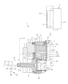
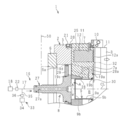
- FIG. 1 It is a figure which shows the chuck provided with the dustproof mechanism by embodiment of this invention. It is a figure which shows the state which took out the claw from the chuck of FIG. It is a view III of FIG. 2, and is the figure which shows the cross section of the chuck in the state which the drive member was advanced. It is an enlarged view of a part of IV vision of FIG. It is a perspective view which shows the 2nd seal member of FIG. 3 with the master jaw and the claw guide member omitted. It is a figure which shows the VI-VI line cross section of FIG. It is a figure which shows the state which the drive member was retracted.
- the chuck 1 is fixed to the spindle 50 (FIG. 3) of a machine tool such as an NC lathe.
- the chuck 1 includes a chuck main body 2, a master jaw 7 provided on the chuck main body 2, and a drive member 8 provided inside the chuck main body 2.
- the chuck body 2 has a mounting groove 3 extending in the radial direction, and the work W is clamped by a claw 4 mounted on the mounting groove 3.
- the work W is conveyed to the chuck 1 by a loader 51 exemplified as a transfer device.
- the work W clamped to the chuck 1 is processed by moving the tool post (not shown) having a plurality of cutting tools in the front-back and left-right directions.
- the claw 4 is replaced manually or by an automatic claw replacement device (not shown) when the diameter of the work W to be machined changes or when wear occurs due to long-term use.
- the chuck body 2 has a front body 5 and a rear body 6 provided on the rear end surface of the front body 5 by mounting bolts (not shown).
- a plurality (for example, three) mounting grooves 3 are provided on the front surface of the front body 5.
- the mounting grooves 3 are arranged at equal intervals in the circumferential direction.
- the front body 5 includes a cylindrical first inner peripheral surface 5a and a cylindrical second inner peripheral surface 5b.
- the first inner peripheral surface 5a is provided on the rear side
- the second inner peripheral surface 5b is provided on the front side.
- the diameter of the second inner peripheral surface 5b is smaller than the diameter of the first inner peripheral surface 5a.
- the front side means the side to which the claw 4 can be attached
- the rear side means the side of the spindle 50 of the machine tool.
- the master jaw 7 is arranged in each guide groove 25 of the front body 5.
- the guide groove 25 is arranged so as to correspond to the mounting groove 3 described above, and extends in the radial direction. As shown in FIGS. 3 and 4, each guide groove 25 forms a continuous space with the corresponding mounting groove 3.
- the master jaw 7 can be moved in the radial direction in the guide groove 25.
- the master jaw 7 is provided with a connecting member 12 that can advance and retreat.
- the connecting member 12 includes a rack-shaped connecting portion 12a that can be connected to the connecting surface 4a (described later) of the claw 4.
- the connecting member 12 is movable between a connecting position connected to the claw 4 and a release position away from the claw 4.
- the connecting portion 12a is adapted to engage with the connecting surface 4a.
- the claw 4 includes a base jaw 13 and a top jaw 15 fixed to the front surface of the base jaw 13 with a plurality of bolts 14.
- the base jaw 13 is inserted into the mounting groove 3.
- the mounting groove 3 is formed in front of the master jaw 7 inserted into the guide groove 25.
- a connecting surface 4a is provided on the rear surface of the base jaw 13.
- the mounting surface 11 is formed on the outer peripheral surface of the front body 5 of the chuck body 2 at a position corresponding to each mounting groove 3 (position on the outer peripheral side of the mounting groove 3). .. As shown in FIGS. 4 and 5, the mounting surface 11 is formed flat from the mounting groove 3 to the guide groove 25. As shown in FIG. 4, a claw guide member 10 is attached to the attachment surface 11 by a bolt 26. The claw guide member 10 is configured to guide the newly attached claw 4 to the mounting groove 3 of the chuck body 2 when the claw guide member 10 is replaced manually or by an automatic claw replacement device (not shown).
- the driving member 8 drives the master jaw 7.
- the drive member 8 has a draw screw 27, a wedge plunger 28, and a retainer 29.
- the draw screw 27, the wedge plunger 28, and the retainer 29 are integrally movable along the central axis CL.
- the draw screw 27 is arranged so as to be centered on the central axis CL of the chuck body 2.
- the wedge plunger 28 is attached to the front surface of the draw screw 27.
- the wedge plunger 28 has a wedge engaging groove 28a, and the wedge portion 7a of the master jaw 7 is engaged with the wedge engaging groove 28a.
- the wedge engaging groove 28a is inclined with respect to the central axis CL.
- the retainer 29 is interposed between the draw screw 27 and the front body 5.
- the retainer 29 is arranged between the first inner peripheral surface 5a of the front body 5 and the outer peripheral surface of the draw screw 27.
- the retainer 29 is attached to the draw screw 27 and is slidable on the first inner peripheral surface 5a of the front body 5.
- the draw screw 27 is held by the wedge plunger 28 in the drive guide member 9 described later, and is held in the front body 5 by the retainer 29.
- each master jaw 7 has a radius along the guide groove 25. It is configured to move in the direction. That is, as shown in FIG. 3, when the driving member 8 advances, each master jaw 7 moves outward in the radial direction. On the other hand, as shown in FIG. 7, when the driving member 8 retracts, each master jaw 7 moves inward in the radial direction. As a result, when the claw 4 is connected to the connecting member 12 of the master jaw 7, the claw 4 can be moved outward in the radial direction by advancing the driving member 8, and by retreating the driving member 8. The claw 4 can be moved inward in the radial direction.
- a drive guide member 9 (also referred to as a pilot bushing) is provided inside the front body 5.
- the drive guide member 9 is configured to guide the movement of the drive member 8. More specifically, the drive guide member 9 includes a cylindrical portion 9a and a rear end portion 9b provided at the rear end portion of the cylindrical portion 9a.
- the cylindrical portion 9a is formed concentrically with the central axis CL.
- the front end portion of the cylindrical portion 9a is attached to the second inner peripheral surface 5b of the front body 5.
- the outer peripheral surface of the cylindrical portion 9a is a guide surface for guiding the movement of the wedge plunger 28 attached to the drive member 8.
- the rear end portion 9b is formed perpendicular to the central axis CL and faces the front surface of the drive member 8.
- An external space B is formed inside the cylindrical portion 9a.
- the external space B is open at the front surface of the chuck body 2. A part of the work W can be inserted into the external space B when the claw 4 clamps the work W.
- the first cover member 30 is attached to the front surface of each master jaw 7.
- the first cover member 30 extends inward in the radial direction from the corresponding master jaw 7 beyond the cylindrical portion 9a of the drive guide member 9.
- a second cover member 31 is attached between the first cover members 30 adjacent to each other in the circumferential direction.
- the first cover member 30 and the second cover member 31 provide a gap between the radial inner end of the master jaw 7 and the front body 5, and between the front body 5 and the cylindrical portion 9a of the drive guide member 9. The gap is covered. Therefore, foreign matter such as chips and cutting oil is prevented from entering these gaps.
- the above-mentioned external space B is open inside the first cover member 30 and the second cover member 31 in the radial direction.
- the chuck 1 is provided with a dustproof mechanism 16 for preventing foreign matter such as chips and cutting oil generated during machining of the work W from entering the inside of the chuck 1.
- the dustproof mechanism 16 is configured to supply a supply fluid to the internal space A formed by the front body 5 and the drive member 8 and the like via the drive member 8 that operates the chuck 1, and pressurize the internal space A. Has been done. Further, the dustproof mechanism 16 is configured to supply the pressurized fluid in the internal space A to the discharge gap 32 described later of the chuck body 2 and discharge the pressurized fluid from the discharge gap 32 to the outside of the chuck body 2.
- the dustproof mechanism 16 includes an air supply source 18 exemplified as a fluid supply source, an internal space A provided inside the chuck 1, and a discharge gap provided in the chuck 1. 32 and.
- the air supply source 18 supplies supply air as an example of the supply fluid to the discharge gap 32.
- the air supply source 18 may be configured to send air as supply air into the internal space A.
- the supply fluid is not limited to air, and may be a gas other than air that is easy to handle, or may be a liquid.
- the internal space A is connected to the air supply source 18, and pressurizes the supply air supplied from the air supply source 18.
- the internal space A includes a space defined by the front body 5, the master jaw 7, the drive member 8, and the drive guide member 9.
- the internal space A is used as a term meaning a space formed between components adjacent to each other inside the chuck 1.
- the internal space A has a configuration in which a plurality of spaces including minute gaps are communicated with each other so as to form a flow path through which air passes.
- the volume of the space defined between the front surface of the drive member 8 and the rear end portion 9b of the drive guide member 9 is determined in FIG. 3 when the drive member 8 is retracted as shown in FIG.
- the drive member 8 is larger than the case where the drive member 8 is advanced.
- the through flow path 27a penetrates the draw screw 27 of the drive member 8.
- the through flow path 27a may extend along the central axis CL.
- the through flow path 27a opens at the front surface of the draw screw 27 and communicates with the internal space A.
- One end of the supply pipe 17 is connected to the through flow path 27a.
- An air supply source 18 is connected to the other end of the supply pipe 17. The supply air from the air supply source 18 is supplied to the internal space A of the chuck body 2 via the supply pipe 17 and the through flow path 27a.
- the discharge gap 32 is a gap for discharging pressurized air from the internal space A to the outside of the chuck body.
- the discharge gap 32 may be a gap between the guide groove 25 provided in the front body 5 extending in the radial direction and the master jaw 7 inserted in the guide groove 25. More specifically, as shown in FIGS. 2 to 4, the discharge gap 32 is the gap between the guide groove 25 and the side surface 7b of the master jaw 7 (see FIGS. 4 and 6) of the chuck body 2. There may be a gap that opens to the front surface (the surface on which the claw 4 is attached).
- the discharge gap 32 communicates with the mounting groove 3 to which the claw 4 is mounted. Therefore, when the claw 4 is attached to the mounting groove 3, pressurized air is discharged from the discharge gap 32 to the outside of the chuck body 2 through the gap between the claw 4 and the mounting groove 3. It has become so.
- the dustproof mechanism 16 is provided with a first seal provided in a gap other than the discharge gap 32 among the gaps provided in the chuck body 2.
- Members 19a to 19d may be provided.
- the first seal members 19a to 19d may be provided in a plurality of gaps of the chuck 1.
- the first seal member 19a may be provided in the gap between the front body 5 and the first cover member 30.
- the first seal member 19b may be provided in the gap between the front body 5 and the cylindrical portion 9a of the drive guide member 9.
- the first seal member 19c may be provided in the gap between the draw screw 27 and the retainer 29, or the first seal member 19d may be provided in the gap between the retainer 29 and the front body 5.
- Each of the first seal members 19a to 19d may be an O-ring made of an elastic material such as rubber.
- the dustproof mechanism 16 covers the gap between the master jaw 7 and the guide groove 25 from the outside in the radial direction.
- the second seal member 20 may be provided.
- the master jaw 7 protrudes above the second seal member 20.
- the second seal member 20 is in contact with the mounting surface 11 formed on the outer peripheral surface of the front body 5, and is in contact with the side surface 7b and the rear surface 7c of the master jaw 7.
- the gap between the master jaw 7 and the guide groove 25 is covered and sealed from the outside in the radial direction.
- the second seal member 20 is formed so as to partially surround the master jaw 7 when viewed from the outside in the radial direction. More specifically, the second seal member 20 is in contact with both side surfaces 7b of the master jaw 7 and the rear surface 7c, and is formed in a rectangular frame shape in which a part is cut out. In this way, the second seal member 20 covers the gap between the side surface 7b and the rear surface 7c of the master jaw 7 and the guide groove 25 from the outside in the radial direction.
- the second seal member 20 may be fixed to the mounting surface 11 by a plurality of bolt members 21.
- the second seal member 20 may be made of an elastic material such as rubber.
- the second seal member 20 may be made of a resin material that is harder than an elastic material such as rubber.
- a layer of an elastic material such as rubber may be formed on the contact surface of the second seal member 20 with the master jaw 7 and the contact surface with the mounting surface 11.
- the dustproof mechanism 16 may include a flow rate adjusting valve 22 exemplified as a supply amount adjusting unit.
- the flow rate adjusting valve 22 may be attached to the supply pipe 17 so as to be able to adjust the supply amount of the supply air supplied from the air supply source 18 to the internal space A.
- the flow rate adjusting valve 22 adjusts the discharge amount of the pressurized air discharged from the gap of the chuck body 2.
- the flow rate adjusting valve 22 may be controlled by a control device (not shown) when the claw 4 is replaced by the claw automatic replacement device. Alternatively, the flow rate adjusting valve 22 may be manually operated when the claw 4 is manually replaced.
- the dustproof mechanism 16 may further include a mixing portion 33 that mixes a lubricant into the supply air. If the pressurized air is continuously discharged from the internal space A to the outside, the lubricant pre-applied to the components constituting the chuck 1 may be removed, which may affect the operation of the chuck 1. Therefore, the dustproof mechanism 16 may be configured so that the lubricant can be mixed into the supply air supplied from the air supply source 18. More specifically, the mixing unit 33 includes a lubricant supply pump 34 that supplies a lubricant (for example, lubricating oil) to the supply pipe 17, and a mixing pipe 35 that connects the lubricant supply pump 34 and the supply pipe 17. , May have.
- a lubricant supply pump 34 that supplies a lubricant (for example, lubricating oil) to the supply pipe 17, and a mixing pipe 35 that connects the lubricant supply pump 34 and the supply pipe 17.
- the lubricant stored in the lubricant storage portion (not shown) is supplied to the supply pipe 17 by the lubricant supply pump 34 and mixed into the supply air in the form of mist.
- the supply air mixed with the lubricant is supplied to the internal space A and is pressurized.
- a distribution valve 36 exemplified as a mixing amount adjusting unit may be attached to the mixing pipe 35.
- the distribution valve 36 adjusts the amount of the lubricant mixed in the supply air supplied to the internal space A of the chuck 1.
- the distribution valve 36 may be controlled by a control device (not shown) when the claw 4 is replaced by the claw automatic replacement device. Alternatively, the distribution valve 36 may be manually operated if the claw 4 is manually replaced.
- the supply air supplied from the air supply source 18 to the internal space A is pressurized, and the pressurized air in the internal space A passes through the discharge gap 32 to the internal space A. Is discharged to the outside of the chuck 1.
- the pressurized air is discharged from the internal space A through the discharge gap 32 to the outside, the configuration of the air supply flow path can be simplified. Therefore, it is possible to prevent the intrusion of foreign matter with a simple configuration.
- the through flow path 27a for communicating the air supply source 18 and the internal space A penetrates the draw screw 27 of the drive member 8 that drives the master jaw 7. This makes it possible to simplify the configuration of the air supply flow path.
- the through flow path 27a extends along the central axis CL. As a result, the pressurized air can be evenly supplied to the discharge gaps 32 defined by the master jaws 7 arranged at different positions in the circumferential direction. Further, it is possible to prevent the rotation balance of the chuck 1 from being reduced, and it is possible to reduce the vibration generated by the rotation.
- the first seal members 19a to 19d are provided in the gaps other than the discharge gap 32 of the chuck 1.
- the gaps other than the discharge gap 32 can be sealed by the first seal members 19a to 19d, and the pressurized air can be prevented from being discharged to the outside from the gap. Therefore, the pressurized air can be centrally supplied to the discharge gap 32, and the discharge amount (or discharge speed) of the pressurized air from the discharge gap 32 can be increased. As a result, it is possible to further prevent foreign matter from entering the inside through the discharge gap 32 from the outside of the chuck 1.
- the discharge gap 32 is a gap between the guide groove 25 provided in the chuck main body 2 in the radial direction and the master jaw 7 inserted into the guide groove 25. ..
- a work W is attached to the front surface of the chuck 1 by a claw 4, and processing is performed.
- the discharge gap 32 is a gap between the guide groove 25 provided in the chuck main body 2 in the radial direction and the master jaw 7 inserted into the guide groove 25. ..
- a work W is attached to the front surface of the chuck 1 by a claw 4, and processing is performed.
- the discharge gap 32 is a gap that opens to the front surface of the chuck 1 among the gaps between the guide groove 25 and the master jaw 7. As a result, by discharging pressurized air from the discharge gap 32 that opens on the front surface of the chuck 1, it is possible to further prevent foreign matter such as chips and lubricant from entering the discharge gap 32. ..
- the gap between the master jaw 7 and the guide groove 25 is covered by the second seal member 20 from the outside in the radial direction.
- the portion of the gap between the master jaw 7 and the guide groove 25 that is open on the outer peripheral surface of the chuck body 2 can be sealed with the second seal member 20, and the portion is added from the portion.
- the pressurized air can be concentratedly supplied to the discharge gap 32 which opens in the front surface of the chuck 1 among the gaps between the guide groove 25 and the master jaw 7, and the pressurized air from the discharge gap 32 can be supplied. It is possible to increase the discharge amount of. As a result, it is possible to further prevent foreign matter from entering the inside through the discharge gap 32 from the outside of the chuck 1.
- the supply amount of the supply air supplied from the air supply source 18 to the internal space A is adjusted by the flow rate adjusting valve 22.
- the amount of pressurized air discharged from the discharge gap 32 can be changed when the claw 4 of the chuck 1 is replaced, when the work W is processed, and when the chuck 1 is on standby. Therefore, the pressurized air can be efficiently discharged. For example, when there is a high possibility that foreign matter invades, the discharge amount of pressurized air can be increased, and the invasion of foreign matter can be effectively prevented.
- the discharge amount of the pressurized air when the claw 4 is replaced, foreign substances such as chips and lubricants adhering to the newly attached claw 4 can be blown off by the pressurized air. Therefore, it is possible to further prevent foreign matter from entering the discharge gap 32.
- the discharge amount of the pressurized air may be increased as compared with the processing of the work W, and in this case, the invasion of foreign matter can be further prevented.
- foreign matter such as chips and lubricant is generated in front of the chuck 1. Therefore, by increasing the discharge amount of the pressurized air, it is possible to further prevent the foreign matter from entering the discharge gap 32. Can be done.
- the chuck 1 when the chuck 1 is on standby, it is unlikely that foreign matter will enter, so that the amount of pressurized air discharged can be reduced, and the amount of air used can be reduced.
- the lubricant is mixed in the supply air.
- the supply air mixed with the lubricant can be supplied to the internal space A. Therefore, the lubricant can be attached to the parts from which the lubricant has been removed by the pressurized air. Therefore, movable parts such as the master jaw 7 and the driving member 8 in the chuck 1 can be smoothly moved.
- the amount of the lubricant mixed in the supply air is adjusted by the distribution valve 36.
- the lubricant can be efficiently adhered.
- the discharge amount of the pressurized air is increased when the claw 4 is replaced or the work W is processed, it is highly likely that the lubricant is removed by the pressurized air.
- the lubricant can be efficiently adhered to each component by increasing the amount of the lubricant mixed.
- the discharge amount of the pressurized air is reduced while the chuck 1 is on standby, it is considered unlikely that the lubricant is removed by the pressurized air.
- the amount of the lubricant used can be reduced by reducing the amount of the lubricant mixed.
- the present invention is not limited to the above-described embodiment, and can be carried out by appropriately modifying a part of the configuration within a range not deviating from the gist of the invention.
Landscapes
- Engineering & Computer Science (AREA)
- Mechanical Engineering (AREA)
- Gripping On Spindles (AREA)
- Auxiliary Devices For Machine Tools (AREA)
Abstract
Description
チャックの内部への異物の侵入を防止するためのチャックの防塵機構であって、
流体供給源と、
前記チャックの内部に設けられ、前記流体供給源から供給される供給流体が加圧流体となって通過する内部空間と、
前記チャックに設けられ、前記内部空間から前記チャックの外部に前記加圧流体を吐出する吐出隙間と、を備えた、チャックの防塵機構、
を提供する。
前記流体供給源と前記内部空間とを連通し、前記チャックのマスタージョーを駆動する駆動部材を貫通する貫通流路を更に備えた、
ようにしてもよい。
前記貫通流路は、前記チャックの中心軸線に沿って延びている、
ようにしてもよい。
前記チャックの前記吐出隙間以外の隙間に設けられた第1シール部材を更に備えた、
ようにしてもよい。
前記吐出隙間は、前記チャックのチャック本体に設けられた半径方向に延びるガイド溝と、前記ガイド溝に挿入されたマスタージョーとの間の隙間である、
ようにしてもよい。
前記吐出隙間は、前記ガイド溝と前記マスタージョーとの間の隙間のうち前記チャックのうち爪が取り付けられる側の面に開口する隙間である、
ようにしてもよい。
前記マスタージョーと前記ガイド溝との間の隙間を半径方向外側から覆う第2シール部材を更に備えた、
ようにしてもよい。
前記供給流体の供給量を調整する供給量調整部を更に備えた、
ようにしてもよい。
前記供給流体に潤滑剤を混入する混入部を更に備えた、
ようにしてもよい。
前記混入部は、前記供給流体に混入される潤滑剤の混入量を調整する混入量調整部を有している、
ようにしてもよい。
上述したチャックの防塵機構を備えた、チャック、
を提供する。
Claims (11)
- チャックの内部への異物の侵入を防止するためのチャックの防塵機構であって、
流体供給源と、
前記チャックの内部に設けられ、前記流体供給源から供給される供給流体が加圧流体となって通過する内部空間と、
前記チャックに設けられ、前記内部空間から前記チャックの外部に前記加圧流体を吐出する吐出隙間と、を備えた、チャックの防塵機構。 - 前記流体供給源と前記内部空間とを連通し、前記チャックのマスタージョーを駆動する駆動部材を貫通する貫通流路を更に備えた、請求項1に記載のチャックの防塵機構。
- 前記貫通流路は、前記チャックの中心軸線に沿って延びている、請求項2に記載のチャックの防塵機構。
- 前記チャックの前記吐出隙間以外の隙間に設けられた第1シール部材を更に備えた、請求項1~3のいずれか一項に記載のチャックの防塵機構。
- 前記吐出隙間は、前記チャックのチャック本体に設けられた半径方向に延びるガイド溝と、前記ガイド溝に挿入されたマスタージョーとの間の隙間である、請求項1~4のいずれか一項に記載のチャックの防塵機構。
- 前記吐出隙間は、前記ガイド溝と前記マスタージョーとの間の隙間のうち爪が取り付けられる側の面に開口する隙間である、請求項5に記載のチャックの防塵機構。
- 前記マスタージョーと前記ガイド溝との間の隙間を半径方向外側から覆う第2シール部材を更に備えた、請求項6に記載のチャックの防塵機構。
- 前記供給流体の供給量を調整する供給量調整部を更に備えた、請求項1~7のいずれか一項に記載のチャックの防塵機構。
- 前記供給流体に潤滑剤を混入する混入部を更に備えた、請求項1~8のいずれか一項に記載のチャックの防塵機構。
- 前記混入部は、前記供給流体に混入される潤滑剤の混入量を調整する混入量調整部を有している、請求項9に記載のチャックの防塵機構。
- 請求項1~10のいずれか一項に記載のチャックの防塵機構を備えた、チャック。
Priority Applications (5)
| Application Number | Priority Date | Filing Date | Title |
|---|---|---|---|
| JP2020547031A JP6849155B2 (ja) | 2019-03-27 | 2020-03-25 | チャックの防塵機構およびチャック |
| KR1020217029576A KR102579143B1 (ko) | 2019-03-27 | 2020-03-25 | 척의 방진 기구 및 척 |
| CN202080023642.7A CN113613818B (zh) | 2019-03-27 | 2020-03-25 | 卡盘的防尘机构和卡盘 |
| EP20776545.4A EP3950191B1 (en) | 2019-03-27 | 2020-03-25 | Chuck having a dust-proof mechanism |
| US17/598,415 US20220184712A1 (en) | 2019-03-27 | 2020-03-25 | Dust-proof mechanism of chuck, and chuck |
Applications Claiming Priority (2)
| Application Number | Priority Date | Filing Date | Title |
|---|---|---|---|
| JP2019061767 | 2019-03-27 | ||
| JP2019-061767 | 2019-03-27 |
Publications (1)
| Publication Number | Publication Date |
|---|---|
| WO2020196582A1 true WO2020196582A1 (ja) | 2020-10-01 |
Family
ID=72612018
Family Applications (1)
| Application Number | Title | Priority Date | Filing Date |
|---|---|---|---|
| PCT/JP2020/013212 Ceased WO2020196582A1 (ja) | 2019-03-27 | 2020-03-25 | チャックの防塵機構およびチャック |
Country Status (7)
| Country | Link |
|---|---|
| US (1) | US20220184712A1 (ja) |
| EP (1) | EP3950191B1 (ja) |
| JP (1) | JP6849155B2 (ja) |
| KR (1) | KR102579143B1 (ja) |
| CN (1) | CN113613818B (ja) |
| TW (1) | TWI737241B (ja) |
| WO (1) | WO2020196582A1 (ja) |
Cited By (2)
| Publication number | Priority date | Publication date | Assignee | Title |
|---|---|---|---|---|
| US11548076B2 (en) * | 2019-07-25 | 2023-01-10 | Pratt & Whitney Canada Corp. | Chuck for machine tool and sealing system |
| WO2025205478A1 (ja) * | 2024-03-25 | 2025-10-02 | 株式会社北川鉄工所 | チャック |
Families Citing this family (2)
| Publication number | Priority date | Publication date | Assignee | Title |
|---|---|---|---|---|
| KR102507946B1 (ko) * | 2018-08-10 | 2023-03-09 | 호와고교 가부시키가이샤 | 척의 움켜잡기 정밀도 확인 방법, 척의 발톱 교환 방법 및 척의 움켜잡기 정밀도 확인 장치 |
| JP2024002119A (ja) * | 2022-06-23 | 2024-01-11 | 株式会社Fuji | ワーク挟持装置、及び工作機械 |
Citations (8)
| Publication number | Priority date | Publication date | Assignee | Title |
|---|---|---|---|---|
| JPS578005A (en) * | 1980-06-10 | 1982-01-16 | Fanuc Ltd | Gripping device with cleaning function |
| JPS63161645U (ja) * | 1987-04-08 | 1988-10-21 | ||
| JPH04136603U (ja) | 1991-06-05 | 1992-12-18 | 豊和工業株式会社 | クイツクチエンジチヤツクの防塵装置 |
| JPH09174313A (ja) * | 1995-12-26 | 1997-07-08 | Honda Motor Co Ltd | 内径把持装置の異物除去装置および異物除去方法 |
| JPH11235632A (ja) * | 1998-02-19 | 1999-08-31 | Toyota Motor Corp | ワークの位置決め固定装置 |
| WO2009093563A1 (ja) * | 2008-01-24 | 2009-07-30 | Kosmek Ltd. | クランプ装置 |
| WO2018092879A1 (ja) | 2016-11-17 | 2018-05-24 | 株式会社北川鉄工所 | チャック |
| WO2018092797A1 (ja) * | 2016-11-15 | 2018-05-24 | 有限会社 シンセテック | 切粉・粉塵防止カバー、切粉・粉塵防止カバーセット、チャック機構及び工作機械 |
Family Cites Families (21)
| Publication number | Priority date | Publication date | Assignee | Title |
|---|---|---|---|---|
| DE3524036A1 (de) * | 1985-07-05 | 1987-01-08 | Heinrich Dipl Phys Quarder | Verschmutzungsschutz fuer bohrfutter |
| JPH0115452Y2 (ja) * | 1985-11-06 | 1989-05-09 | ||
| JPH071208Y2 (ja) * | 1988-04-20 | 1995-01-18 | 富士機械製造株式会社 | ワーク保持装置 |
| JP2001277012A (ja) * | 2000-03-31 | 2001-10-09 | Howa Mach Ltd | チャック |
| TW585146U (en) * | 2001-02-06 | 2004-04-21 | Chandox Prec Ind Co Ltd | Improved structure for vertical hydraulic chuck |
| JP2004009151A (ja) * | 2002-06-03 | 2004-01-15 | Smc Corp | 3方向開閉チャック |
| KR20060037336A (ko) * | 2003-07-25 | 2006-05-03 | 가부시키가이샤 코스멕 | 클램프 장치 |
| DE102007034117B4 (de) * | 2007-07-21 | 2011-03-10 | Ab Skf | Schmiervorrichtung |
| JP5257999B2 (ja) * | 2010-05-31 | 2013-08-07 | 春男 竹好 | チャックにおける把持面の切粉付着防止装置 |
| CN201931322U (zh) * | 2010-12-15 | 2011-08-17 | 嘉兴永佳精密机械制造有限公司 | 一种新型强力夹头的防尘机构 |
| JP2012135846A (ja) * | 2010-12-27 | 2012-07-19 | Honda Motor Co Ltd | チャック構造 |
| TWM423762U (en) * | 2011-10-07 | 2012-03-01 | Dar Harnq Industry Co Ltd | Dustproof spindle device |
| CN202667680U (zh) * | 2012-06-10 | 2013-01-16 | 富阳孙氏机床有限公司 | 用于主轴的多道防尘机构 |
| JP5827602B2 (ja) * | 2012-06-28 | 2015-12-02 | 株式会社コスメック | クランプ装置 |
| KR101495888B1 (ko) * | 2014-11-03 | 2015-03-02 | 유학현 | 에어 블로 중공형 핑거 척 |
| CN205128959U (zh) * | 2015-11-10 | 2016-04-06 | 呼和浩特众环(集团)有限责任公司 | 新型楔式动力卡盘 |
| IT201700014495A1 (it) | 2017-02-09 | 2018-08-09 | Ali Group Srl Carpigiani | Macchina per la produzione e l'erogazione di prodotti liquidi o semiliquidi. |
| JP7167474B2 (ja) * | 2017-04-19 | 2022-11-09 | 豊和工業株式会社 | チャックの部品交換装置 |
| JP7068629B2 (ja) * | 2018-04-27 | 2022-05-17 | 豊和工業株式会社 | 揺動式チャックのシール構造 |
| JP7327771B2 (ja) * | 2018-10-16 | 2023-08-16 | 有限会社 シンセテック | チャック機構、爪装着アダプタ、及び切粉・粉塵防止カバー |
| CN209918921U (zh) * | 2019-04-23 | 2020-01-10 | 浙江京速机床附件有限公司 | 一种内藏式卡盘 |
-
2020
- 2020-03-25 WO PCT/JP2020/013212 patent/WO2020196582A1/ja not_active Ceased
- 2020-03-25 JP JP2020547031A patent/JP6849155B2/ja active Active
- 2020-03-25 EP EP20776545.4A patent/EP3950191B1/en active Active
- 2020-03-25 KR KR1020217029576A patent/KR102579143B1/ko active Active
- 2020-03-25 CN CN202080023642.7A patent/CN113613818B/zh active Active
- 2020-03-25 US US17/598,415 patent/US20220184712A1/en not_active Abandoned
- 2020-03-26 TW TW109110305A patent/TWI737241B/zh active
Patent Citations (8)
| Publication number | Priority date | Publication date | Assignee | Title |
|---|---|---|---|---|
| JPS578005A (en) * | 1980-06-10 | 1982-01-16 | Fanuc Ltd | Gripping device with cleaning function |
| JPS63161645U (ja) * | 1987-04-08 | 1988-10-21 | ||
| JPH04136603U (ja) | 1991-06-05 | 1992-12-18 | 豊和工業株式会社 | クイツクチエンジチヤツクの防塵装置 |
| JPH09174313A (ja) * | 1995-12-26 | 1997-07-08 | Honda Motor Co Ltd | 内径把持装置の異物除去装置および異物除去方法 |
| JPH11235632A (ja) * | 1998-02-19 | 1999-08-31 | Toyota Motor Corp | ワークの位置決め固定装置 |
| WO2009093563A1 (ja) * | 2008-01-24 | 2009-07-30 | Kosmek Ltd. | クランプ装置 |
| WO2018092797A1 (ja) * | 2016-11-15 | 2018-05-24 | 有限会社 シンセテック | 切粉・粉塵防止カバー、切粉・粉塵防止カバーセット、チャック機構及び工作機械 |
| WO2018092879A1 (ja) | 2016-11-17 | 2018-05-24 | 株式会社北川鉄工所 | チャック |
Non-Patent Citations (1)
| Title |
|---|
| See also references of EP3950191A4 |
Cited By (2)
| Publication number | Priority date | Publication date | Assignee | Title |
|---|---|---|---|---|
| US11548076B2 (en) * | 2019-07-25 | 2023-01-10 | Pratt & Whitney Canada Corp. | Chuck for machine tool and sealing system |
| WO2025205478A1 (ja) * | 2024-03-25 | 2025-10-02 | 株式会社北川鉄工所 | チャック |
Also Published As
| Publication number | Publication date |
|---|---|
| TW202042940A (zh) | 2020-12-01 |
| US20220184712A1 (en) | 2022-06-16 |
| EP3950191A4 (en) | 2022-12-07 |
| TWI737241B (zh) | 2021-08-21 |
| JP6849155B2 (ja) | 2021-03-24 |
| CN113613818A (zh) | 2021-11-05 |
| CN113613818B (zh) | 2024-05-17 |
| KR20210125571A (ko) | 2021-10-18 |
| EP3950191B1 (en) | 2025-07-02 |
| KR102579143B1 (ko) | 2023-09-18 |
| JPWO2020196582A1 (ja) | 2021-04-08 |
| EP3950191A1 (en) | 2022-02-09 |
Similar Documents
| Publication | Publication Date | Title |
|---|---|---|
| JP6849155B2 (ja) | チャックの防塵機構およびチャック | |
| US10632583B1 (en) | Through-coolant vibration dampened machine tool having resilient dampening system | |
| US10130997B2 (en) | Main shaft device and machine tool provided with same | |
| CN102189440A (zh) | 加工装置 | |
| US20210008641A1 (en) | Lathe | |
| US10226845B2 (en) | Machine tool | |
| US20020033582A1 (en) | Method and device for the dynamic lubrication of a power chuck | |
| JP6441403B2 (ja) | 切削工具保持機構、切削工具ホルダおよび工作機械システム | |
| KR101448237B1 (ko) | 다기능 건드릴머신용 주축대 | |
| US12611744B2 (en) | Spindle and cutting apparatus including the same | |
| KR102134486B1 (ko) | 공작기계의 주축 관통 쿨런트 및 에어 공급장치 | |
| JP2007307679A (ja) | 主軸装置 | |
| JP5016314B2 (ja) | 穴の切粉清掃工具 | |
| KR101280789B1 (ko) | 공작기계의 절삭유 공급 장치 | |
| JP4530677B2 (ja) | 工作機械用工具ホルダ | |
| KR102772879B1 (ko) | 공작기계의 워크피스 이젝터 장치 | |
| US8893595B2 (en) | Chuck device having two collets | |
| KR20210009058A (ko) | Cnc 드릴링머신의 절삭유 공급장치 | |
| KR20130022903A (ko) | 공작기계용 주축장치 | |
| KR20140086043A (ko) | 머시닝 센터용 공구 클램프 및 언클램프 장치 | |
| JP4905857B2 (ja) | 回転シリンダ | |
| KR20190138097A (ko) | 밀링 헤드장치 | |
| JP2000126981A (ja) | 切削油供給装置を備えた工作機械 | |
| JP2005088183A (ja) | ツールホルダ | |
| KR200433532Y1 (ko) | 터렛공구대의 절삭유 공급장치 |
Legal Events
| Date | Code | Title | Description |
|---|---|---|---|
| ENP | Entry into the national phase |
Ref document number: 2020547031 Country of ref document: JP Kind code of ref document: A |
|
| 121 | Ep: the epo has been informed by wipo that ep was designated in this application |
Ref document number: 20776545 Country of ref document: EP Kind code of ref document: A1 |
|
| ENP | Entry into the national phase |
Ref document number: 20217029576 Country of ref document: KR Kind code of ref document: A |
|
| NENP | Non-entry into the national phase |
Ref country code: DE |
|
| ENP | Entry into the national phase |
Ref document number: 2020776545 Country of ref document: EP Effective date: 20211027 |
|
| WWG | Wipo information: grant in national office |
Ref document number: 2020776545 Country of ref document: EP |