WO2020208887A1 - 金属製箱体 - Google Patents
金属製箱体 Download PDFInfo
- Publication number
- WO2020208887A1 WO2020208887A1 PCT/JP2020/000384 JP2020000384W WO2020208887A1 WO 2020208887 A1 WO2020208887 A1 WO 2020208887A1 JP 2020000384 W JP2020000384 W JP 2020000384W WO 2020208887 A1 WO2020208887 A1 WO 2020208887A1
- Authority
- WO
- WIPO (PCT)
- Prior art keywords
- box body
- side wall
- metal box
- bottom portion
- welded
- Prior art date
- Legal status (The legal status is an assumption and is not a legal conclusion. Google has not performed a legal analysis and makes no representation as to the accuracy of the status listed.)
- Ceased
Links
Images











Classifications
-
- B—PERFORMING OPERATIONS; TRANSPORTING
- B23—MACHINE TOOLS; METAL-WORKING NOT OTHERWISE PROVIDED FOR
- B23K—SOLDERING OR UNSOLDERING; WELDING; CLADDING OR PLATING BY SOLDERING OR WELDING; CUTTING BY APPLYING HEAT LOCALLY, e.g. FLAME CUTTING; WORKING BY LASER BEAM
- B23K33/00—Specially-profiled edge portions of workpieces for making soldering or welding connections; Filling the seams formed thereby
- B23K33/004—Filling of continuous seams
-
- B—PERFORMING OPERATIONS; TRANSPORTING
- B65—CONVEYING; PACKING; STORING; HANDLING THIN OR FILAMENTARY MATERIAL
- B65D—CONTAINERS FOR STORAGE OR TRANSPORT OF ARTICLES OR MATERIALS, e.g. BAGS, BARRELS, BOTTLES, BOXES, CANS, CARTONS, CRATES, DRUMS, JARS, TANKS, HOPPERS, FORWARDING CONTAINERS; ACCESSORIES, CLOSURES, OR FITTINGS THEREFOR; PACKAGING ELEMENTS; PACKAGES
- B65D7/00—Containers having bodies formed by interconnecting or uniting two or more rigid, or substantially rigid, components made wholly or mainly of metal
- B65D7/12—Containers having bodies formed by interconnecting or uniting two or more rigid, or substantially rigid, components made wholly or mainly of metal characterised by wall construction or by connections between walls
- B65D7/34—Containers having bodies formed by interconnecting or uniting two or more rigid, or substantially rigid, components made wholly or mainly of metal characterised by wall construction or by connections between walls with permanent connections between walls
- B65D7/38—Containers having bodies formed by interconnecting or uniting two or more rigid, or substantially rigid, components made wholly or mainly of metal characterised by wall construction or by connections between walls with permanent connections between walls formed by soldering, welding, or otherwise uniting opposed surfaces
-
- B—PERFORMING OPERATIONS; TRANSPORTING
- B23—MACHINE TOOLS; METAL-WORKING NOT OTHERWISE PROVIDED FOR
- B23K—SOLDERING OR UNSOLDERING; WELDING; CLADDING OR PLATING BY SOLDERING OR WELDING; CUTTING BY APPLYING HEAT LOCALLY, e.g. FLAME CUTTING; WORKING BY LASER BEAM
- B23K33/00—Specially-profiled edge portions of workpieces for making soldering or welding connections; Filling the seams formed thereby
-
- B—PERFORMING OPERATIONS; TRANSPORTING
- B65—CONVEYING; PACKING; STORING; HANDLING THIN OR FILAMENTARY MATERIAL
- B65D—CONTAINERS FOR STORAGE OR TRANSPORT OF ARTICLES OR MATERIALS, e.g. BAGS, BARRELS, BOTTLES, BOXES, CANS, CARTONS, CRATES, DRUMS, JARS, TANKS, HOPPERS, FORWARDING CONTAINERS; ACCESSORIES, CLOSURES, OR FITTINGS THEREFOR; PACKAGING ELEMENTS; PACKAGES
- B65D7/00—Containers having bodies formed by interconnecting or uniting two or more rigid, or substantially rigid, components made wholly or mainly of metal
- B65D7/02—Containers having bodies formed by interconnecting or uniting two or more rigid, or substantially rigid, components made wholly or mainly of metal characterised by shape
- B65D7/06—Containers having bodies formed by interconnecting or uniting two or more rigid, or substantially rigid, components made wholly or mainly of metal characterised by shape of polygonal cross-section, e.g. tins, boxes
-
- F—MECHANICAL ENGINEERING; LIGHTING; HEATING; WEAPONS; BLASTING
- F16—ENGINEERING ELEMENTS AND UNITS; GENERAL MEASURES FOR PRODUCING AND MAINTAINING EFFECTIVE FUNCTIONING OF MACHINES OR INSTALLATIONS; THERMAL INSULATION IN GENERAL
- F16B—DEVICES FOR FASTENING OR SECURING CONSTRUCTIONAL ELEMENTS OR MACHINE PARTS TOGETHER, e.g. NAILS, BOLTS, CIRCLIPS, CLAMPS, CLIPS OR WEDGES; JOINTS OR JOINTING
- F16B5/00—Joining sheets or plates, e.g. panels, to one another or to strips or bars parallel to them
- F16B5/08—Joining sheets or plates, e.g. panels, to one another or to strips or bars parallel to them by means of welds or the like
-
- B—PERFORMING OPERATIONS; TRANSPORTING
- B23—MACHINE TOOLS; METAL-WORKING NOT OTHERWISE PROVIDED FOR
- B23K—SOLDERING OR UNSOLDERING; WELDING; CLADDING OR PLATING BY SOLDERING OR WELDING; CUTTING BY APPLYING HEAT LOCALLY, e.g. FLAME CUTTING; WORKING BY LASER BEAM
- B23K2101/00—Articles made by soldering, welding or cutting
- B23K2101/04—Tubular or hollow articles
Definitions
- the present invention relates to a metal box body.
- Patent Document 1 instead of deep drawing, a tubular side wall portion formed by bending a metal plate into a tubular shape and welding the ends to each other and a plate-shaped bottom portion cut out from the metal plate are prepared.
- the configuration of a box body formed by welding the bottom portion so as to cover the open end of the tubular side wall portion is disclosed.
- the bottom is welded to a seamless pipe-shaped member formed by extrusion or withdrawal.
- the depth of the box body is not limited and the variation in wall thickness can be suppressed.
- the present invention has been made in view of this background, and an object of the present invention is to provide a metal box body which has good workability at the time of welding and can be stably placed on a mounting surface.
- One aspect of the present invention is a metal box body having a bottom portion made of a metal plate and a side wall portion made of a metal plate erected from the outer peripheral edge of the bottom portion.
- the boundary portion between the bottom portion and the side wall portion includes a welded portion formed by welding both portions.
- the welded portion is exposed on the surface of the metal box body below the side wall portion in the erection direction.
- the bottom portion is in a metal box body having a lower end portion located below the welded portion in the vertical direction.
- the welded portion included in the boundary portion between the bottom portion and the side wall portion erected from the outer peripheral edge thereof is exposed on the surface below the side wall portion in the erection direction, but the bottom portion is from the welded portion. Since it also has a lower end located below the erection direction, even if a weld is formed by welding from below the erection direction, the irregularly shaped weld bead contained in the weld will be present from the lower end of the bottom. Does not protrude downward. Therefore, when the metal box body is placed on the mounting surface, the lower end portion of the bottom portion abuts on the mounting surface, and the weld bead of the welded portion does not abut on the mounting surface. As a result, the welding workability is good, and the metal box body can be stably placed.
- FIG. 4A in Example 1 It is a partially enlarged view of FIG. 4A in Example 1.
- FIG. 4B is a partially enlarged view of FIG. 4B in the first embodiment. It is sectional drawing of the metal box body before welding in the modification 1.
- FIG. 4B is sectional drawing of the metal box body after welding in the modification 1.
- FIG. 2 It is sectional drawing of the metal box body before welding in the modification 2.
- FIG. It is sectional drawing of the metal box body after welding in the modification 2.
- FIG. It is sectional drawing of the metal box body before welding in the modification 3. It is sectional drawing of the metal box body after welding in the modification 3. It is sectional drawing of the metal box body before welding in the modification 4. It is sectional drawing of the metal box body after welding in the modification 4. It is sectional drawing of the metal box body before welding in Example 2.
- FIG. It is sectional drawing of the metal box body after welding in Example 2.
- FIG. It is sectional drawing of the metal box body before welding in the modification 5.
- the outer peripheral edge of the bottom portion has a flange portion located above the lower end portion of the bottom portion in the vertical direction, and the flange portion and the side wall portion are welded to each other to form the welded portion. It is preferable to have. In this case, it can be used as a guide when welding the flange portion, and the workability of welding is improved.
- the flange portion is formed thinner than the central portion of the bottom portion. In this case, it becomes easy to position the flange portion above the lower end portion of the bottom portion in the vertical direction, and the workability of forming the flange portion is improved.
- the flange portion has a bent portion that is bent upward in the vertical direction and is bent outward in a plan view of the bottom portion.
- the flange portion can be positioned above the lower end portion of the bottom portion in the vertical direction with a simple configuration, and the formability of the flange portion is improved.
- the lower end portion is located below the erection direction within a range of 0.2 to 5.0 mm from the welded portion in the erection direction of the side wall portion. In this case, when the metal box body is placed, the weld bead of the welded portion does not come into contact with the mounting surface, and it is possible to prevent the bottom portion of the metal box body from becoming excessively thick in the erection direction.
- the lower end portion of the bottom portion is formed of a protruding portion that protrudes downward in the vertical direction.
- the protruding portion as the lower end of the bottom portion surely comes into contact with the mounting surface, so that the welded portion hits the mounting surface. It is possible to reliably prevent contact with the metal box, and further improve the stability when the metal box is placed.
- the bottom portion has an inner peripheral contact portion that contacts the inner peripheral surface of the side wall portion. In this case, when the bottom portion is welded to the side wall portion, the positioning of the bottom portion becomes easy and the workability at the time of welding is improved.
- the metal box body 1 of this embodiment has a bottom portion 10 made of a metal plate and a side wall portion 20 made of a metal plate erected from the outer peripheral edge 11 of the bottom portion 10.
- the boundary portion 30 between the bottom portion 10 and the side wall portion 20 includes a welded portion 31 formed by welding both portions.
- the welded portion 31 is exposed on the surface 10a of the side wall portion 20 of the metal box body 1 below Z1 in the vertical direction.
- the lower end portion 12 which is the end portion of the side wall portion 20 of the bottom portion 10 below the erection direction Z1 is located below the welded portion 31 in the erection direction Z1.
- the material for forming the metal box 1 of this embodiment is a metal material, and the properties of the contents contained in the metal box 1, the usage environment of the metal box 1, the moldability of the forming material, and the like are taken into consideration. Can be selected as appropriate. For example, when used as a battery case, stainless steel, steel, titanium, titanium alloy, aluminum, aluminum alloy, etc. can be used in consideration of corrosion resistance and weldability.
- the outer shape of the metal box 1 is not particularly limited, and the shape of the bottom 10 may be a rectangle, a circle, an ellipse, a shape in which the short side of the rectangle is arcuate, or a shape in which the corners of the rectangle are rounded. can do.
- the side wall portion 20 has a shape that is erected on the outer peripheral edge of the bottom portion 10.
- the metal box body 1 has a substantially rectangular parallelepiped shape as shown in FIG. 1, and includes a bottom portion 10 and a side wall portion 20. The opposite side of the bottom 10 is open, forming an opening 40.
- the bottom portion 10 and the side wall portion 20 are integrated by welding those formed as separate bodies from each other.
- the bottom portion 10 has a substantially flat plate shape, and is rectangular in a plan view. Then, the width direction X is the direction parallel to one side of the bottom portion 10 among the surface directions of the bottom portion 10, and the depth direction Y is the direction orthogonal to the width direction X among the surface directions of the bottom portion 10.
- the side wall portion 20 has a tubular shape, and the outer shape of the bottom surface of the side wall portion 20 has a quadrangular shape, and the side wall portion 20 is erected from each side of the bottom portion 10.
- the erection direction Z of the side wall portion 20 is a direction orthogonal to the width direction X and the depth direction Y.
- the side wall portion 20 is formed by bending a metal plate into a tubular shape and welding the end portions against each other.
- the side wall welded portion 22 is formed.
- the side wall welded portion 22 is configured not to be located at the corner portion 23 of the side wall portion 20.
- the lower end 21 of the side wall of the side wall 20 forms a lower end opening 41 that opens in a quadrangular shape.
- a flange portion 13 is provided on the outer peripheral edge 11 of the bottom portion 10.
- the flange portion 13 projects outward from the outer peripheral edge 11 of the bottom portion 10 in the surface direction of the bottom portion 10.
- the method of forming the flange portion 13 on the outer peripheral edge 11 of the bottom portion 10 is not particularly limited, and may be press working, cutting processing, or the like.
- the bottom portion 10 is applied to the side wall lower end portion 21 which is the side wall portion 20 so that the flange portion 13 abuts on the lower end surface 21a of the side wall lower end portion 21 which is the lower end of the side wall portion 20.
- FIG. 5A the bottom portion 10 is applied to the side wall lower end portion 21 which is the side wall portion 20 so that the flange portion 13 abuts on the lower end surface 21a of the side wall lower end portion 21 which is the lower end of the side wall portion 20.
- the flange portion 13 and the lower end portion 21 of the side wall are welded by irradiating a laser as shown by an arrow L from the lower side of the erection direction Z in the drawing toward the upper Z2 in the erection direction.
- a welded portion 31 is formed.
- the direction of irradiating the laser is not limited to the direction parallel to the erection direction Z, and may be the direction from the diagonally lower position of the metal box 1 toward the flange portion 13. In each drawing, the direction of irradiating the laser is from the lower side to the upper side of the drawing, but in reality, it is turned upside down and the direction is from the upper side to the lower side in the direction of gravity.
- the welding method is not limited, and TIG welding or the like may be used instead of laser welding.
- the welded portion 31 is exposed on the surface 10a of the metal box body 1 below Z1 in the vertical direction.
- the entire boundary portion 30 is the welded portion 31.
- the welded portion 31 has a weld bead, and as shown in FIG. 1, is formed in the entire circumferential direction along the outer edge of the bottom portion 10, and has an irregular shape as a whole.
- the side wall portion 20 is located inside the outer peripheral surface 20b in the width direction X.
- the lower end portion 12 is located in the erection direction Z in the erection direction Z by a height H1 higher than the welded portion 31.
- the height H1 can be, for example, in the range of 0.2 to 5.0 mm, and in this example, it is in the range of 0.2 to 1.0 mm.
- the bottom portion 10 includes an inner peripheral contact portion 14 that enters the lower end opening 41 of the side wall portion 20 and abuts on the inner peripheral surface 20a of the side wall portion 20.
- the inner peripheral contact portion 14 is configured to contact at least a pair of surfaces facing each other on the inner peripheral surface 20a of the side wall portion 20, and in this example, the inner peripheral contact portion 14 is the inner peripheral surface 20a. It is in contact with all four surfaces of.
- the thickness of the metal material forming the metal box 1 is not particularly limited, but can be about 0.1 mm to about 2.0 mm.
- the thickness T1 of the bottom portion 10 is 1.5 mm
- the thickness T2 of the side wall portion 20 is 1.0 mm.
- the thickness T3 of the flange portion 13 can be 0.5 mm or more and less than the thickness T1 of the bottom portion 10, and in this example, the thickness T3 is 0.5 mm. That is, the flange portion 13 is formed to be thinner than the central portion of the bottom portion 10.
- the width W of the flange portion 13, that is, the length W of the step portion 15 between the lower end portion 12 and the flange portion 13 in the width direction X can be 0.5 mm or more and less than the thickness T2 of the side wall portion 20. In this example, the width W is 0.8 mm.
- the distance T4 between the lower end portion 12 and the flange portion 13 in the vertical direction Z that is, the depth T4 of the step portion 15 between the lower end portion 12 and the flange portion 13 is 0.5 mm or more.
- the thickness of the bottom 10 can be less than T1, and in this example the thickness T3 is 0.5 mm.
- the thickness T5 from the flange portion 13 in the vertical direction Z of the inner peripheral contact portion 14 can be 0.5 mm or more and less than the thickness T1 of the bottom portion 10. In this example, the thickness T5 is 0. It is 5 mm.
- the welded portion 31 included in the boundary portion 30 between the bottom portion 10 and the side wall portion 20 erected from the outer peripheral edge 11 thereof is on the surface 10a of the side wall portion 20 below the erection direction Z1.
- the bottom portion 10 has the lower end portion 12 located at the lower Z1 in the erection direction with respect to the welded portion 31, even if the welded portion 31 is formed by welding from the lower Z1 in the erection direction.
- the irregularly shaped weld bead included in the welded portion 31 does not protrude from the lower end portion 12 of the bottom portion 10 downward in the vertical direction Z1.
- the lower end portion 12 of the bottom portion 10 abuts on the mounting surface, and the weld bead of the welded portion 31 does not abut on the mounting surface.
- the welding workability is good, and the metal box 1 can be stably placed.
- the outer peripheral edge 11 of the bottom portion 10 has a flange portion 13 located above Z2 in the vertical direction with respect to the lower end portion 12 of the bottom portion 10, and the flange portion 13 and the side wall portion 20 are welded to each other.
- the welded portion 31 is formed.
- the flange portion 13 can be used as a guide when welding, and the workability of welding is improved.
- the flange portion 13 is formed so that the outer peripheral edge 11 of the bottom portion 10 is thinner than the central portion of the bottom portion 10. As a result, the flange portion 13 can be easily positioned above the lower end portion 12 of the bottom portion 10 in the vertical direction, and the workability of molding the flange portion 13 is improved.
- the lower end portion 12 is located in the erection direction Z1 of the side wall portion 20 within a range of 0.2 to 5.0 mm from the welded portion 31 in the erection direction Z.
- the bottom portion 10 has an inner peripheral contact portion 14 that abuts on the inner peripheral surface 20a of the side wall portion 20.
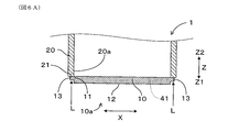
- the bottom portion 10 has the inner peripheral contact portion 14, but instead, the bottom portion 10 has the inner peripheral contact portion 14 as shown in the modified examples 1 shown in FIGS. 6A and 6B. It may be a configuration that does not have.
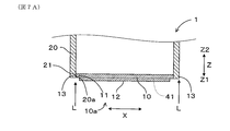
- the flange portion 13 is in contact with the lower end surface 21a of the side wall lower end portion 21 of the side wall portion 20, but instead of this configuration, as in the modified example 2 shown in FIGS. 7A and 7B, A part of the bottom portion 10 may enter the lower end opening 41 of the side wall portion 20, and the flange portion 13 may come into contact with the inner peripheral surface 20a of the side wall portion 20.
- the protrusion 24 may be formed on the inner peripheral surface 20a near the lower end opening 41 of the side wall portion 20. According to the modification 3, the bottom portion 10 can be easily positioned in the erection direction Z by bringing the flange portion 13 into contact with the protrusion 24.
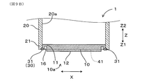
- the tip of the flange portion 13 may be bent downward to the Z1 side in the vertical direction.
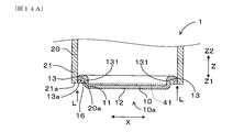
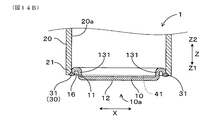
- a recess 16 is formed inside the tip of the flange portion 13, and welding is performed in a state where the tip surface 13a of the flange portion 13 is flush with the lower end surface 21a of the side wall portion 20.
- the protrusion 24 may be formed in the same manner as in the modified example 3 shown in FIGS. 8A and 8B.
- the metal box body 1 which has good workability at the time of welding and can be stably placed on the mounting surface.
- the thickness T1 of the central portion 18 and the thickness T3 of the flange portion 13 are the same thickness at the bottom portion 10, and both are 1.0 mm. ing.
- the bottom portion 10 is formed by pressing a metal plate and bending the outer peripheral edge 11 toward the upper Z2 side in the erection direction to form a step portion 15 to form a flange portion 13.
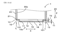
- the flange portion 13 has a bent portion 131 that is bent upward Z2 in the vertical direction and is bent in the width direction X and the depth direction Y, which are the outer sides of the bottom portion 10 in a plan view.
- the same components as those in the first embodiment are designated by the same reference numerals, and the description thereof will be omitted.
- the flange portion 13 can be positioned above the lower end portion 12 of the bottom portion 10 in the vertical direction Z2 with a simple configuration, and the flange portion can be located.
- the moldability of 13 is improved.
- the same action and effect as in the case of Example 1 are exhibited.
- the inner peripheral contact portion 14 that contacts the inner peripheral surface 20a of the side wall portion 20 may be provided on the bottom portion 10 in the configuration of the second embodiment.
- the inner peripheral contact portion 14 can have the same configuration as that of the first embodiment.
- a part of the bottom portion 10 in the configuration of the second embodiment enters the lower end opening 41 of the side wall portion 20, and the flange portion 13 is the inner circumference of the side wall portion 20. It may be configured to abut on the surface 20a.
- the protrusion 24 may be formed on the inner peripheral surface 20a in the vicinity of the lower end opening 41 of the side wall portion 20 as shown in FIGS. 13A and 13B. According to the modification 7, the bottom portion 10 can be easily positioned in the erection direction Z by bringing the flange portion 13 into contact with the protrusion 24.
- the tip of the flange portion 13 in the configuration of the second embodiment may be bent downward in the erection direction to the Z1 side.
- the recess 16 is formed inside the tip of the flange portion 13, and welding is performed in a state where the tip surface 13a of the flange portion 13 is flush with the lower end surface 21a of the side wall portion 20.
- the protrusion 24 may be formed in the same manner as in the modified example 7 shown in FIGS. 13A and 13B.
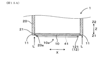
- the bottom portion 10 is formed into a flat plate shape, and the lower end portion 12 of the bottom portion 10 is a protruding portion 121 projecting from the bottom portion 10 downward Z1 in the vertical direction. It may be provided.
- the projecting portion 121 is formed on the entire circumference along the outer peripheral edge 11 at a position inside the outer peripheral edge 11 of the bottom portion 10.
- the height of the protruding portion 121 is not particularly limited, and can be, for example, in the range of 0.5 to 2.0 mm.
- both are welded from below the bottom portion 10 toward the upper Z2 in the erection direction.
- the protrusion 24 may be formed as a protrusion as in the modified example 7 shown in FIGS. 13A and 13B.
- the lower end portion 12 of the bottom portion 10 is composed of a protruding portion 121 protruding downward Z1 in the vertical direction.
- the protruding portion 121 as the lower end portion 12 of the bottom portion 10 surely comes into contact with the mounting surface, so that the welded portion 31 is placed on the mounting surface. It is possible to reliably prevent the metal box body 1 from coming into contact with the metal box body 1, and further improve the stability when the metal box body 1 is placed.
- the second embodiment and the fifth to ninth modifications also provide the metal box body 1 which has good workability at the time of welding and can be stably mounted on the mounting surface. Can be done.
- the bottom portion 10 and the side wall portion 20 are prepared as separate bodies and both are connected by welding.
- the third embodiment as shown in FIG. 16A, before welding.
- the bottom portion 10 and the side wall portion 20 are made of a connected metal plate, and one side of the bottom portion 10 is connected to the side wall portion 20 via a bent portion 32.
- the bottom portion 10 is bent at the bent portion 32, and the flange portion 13 is overlapped with the side wall lower end portion 21 of the side wall portion 20 and irradiated with a laser as shown by an arrow L, and is shown in FIG. 16C.
- the bottom portion 10 and the side wall portion 20 are welded to form the welded portion 31.
- the boundary portion 30 between the bottom portion 10 and the side wall portion 20 includes a welded portion 31 and a bent portion 32. Since the welded portion 31 of the boundary portion 30 is located above the lower end portion 12 of the bottom portion 10 in the vertical direction Z2, the same effect as in the cases of Examples 1 and 2 is obtained.
Landscapes
- Engineering & Computer Science (AREA)
- Mechanical Engineering (AREA)
- General Engineering & Computer Science (AREA)
- Sealing Battery Cases Or Jackets (AREA)
- Rigid Containers With Two Or More Constituent Elements (AREA)
- Laser Beam Processing (AREA)
- Butt Welding And Welding Of Specific Article (AREA)
Abstract
金属製箱体(1)は、金属板からなる底部(10)と、底部(10)の外周縁(11)から立設した金属板からなる側壁部(20)とを有する。底部(10)と側壁部(20)との境界部分(30)は、両者を溶接してなる溶接部(31)を含む。溶接部(31)は、金属製箱体(1)における側壁部(20)の立設方向下方(Z1)の表面(10a)に表出している。そして、底部(10)における側壁部(20)の立設方向下方(Z1)の端部である下端部(12)は、溶接部(31)よりも立設方向下方(Z1)に位置している。
Description
本発明は、金属製箱体に関する。
従来、種々の物品を収容可能な金属製箱体として、プレス機によって金属板を絞り加工して形成された箱体が広く用いられている。しかし、ステンレスやチタンなどの一般的に延性の低い金属材料では、いわゆる深絞り成形を高精度で行うことが困難な場合がある。また、絞り加工では絞り深さに限界があり、この深さの限界を超えて絞り加工を行うと箱体に亀裂が生じてしまうため、深絞り成形では箱体の深さが制限されていた。そこで、特許文献1には、深絞り成形に替えて、金属板を筒状に折り曲げて端部同士を溶接してなる筒状の側壁部と金属板から切り出してなる板状の底部とを用意し、筒状の側壁部の開口端を覆うように底部を溶接して成形された箱体の構成が開示されている。その他の構成として、押し出しや引き抜きで形成した継ぎ目のないパイプ状部材に底部を溶接した構成とすることも考えらえる。これらの構成では、絞り加工を要しないため、箱体の深さが制限されないとともに、肉厚のばらつきが抑えられる。
しかし、特許文献1に開示の構成や上述のその他の構成において、底部と側壁部の境界部が側周面に現れる場合には、両者を溶接する際に筒状の側周面に沿って溶接装置を周方向に大きく動かしたり、溶接対象となる側壁部及び底部を筒状の側周面に沿って周方向に回転させたりする必要があるため作業性が悪い。一方、底部と側壁部の境界部が底面に現れる場合には、溶接装置を側周面に沿って大きく動かしたり、側壁部及び底部を回転させたりする必要がないため、作業性は向上する。しかしながら、溶接により生じる不揃いな形状の溶接ビードが底面に表出して底部よりも膨らんだ状態となるため、箱体を載置したときに溶接ビードが載置面と干渉して、箱体を載置した際の安定性が低下する。
本発明は、かかる背景に鑑みてなされたものであり、溶接時の作業性がよく、載置面に安定して載置可能な金属製箱体を提供しようとするものである。
本発明の一態様は、金属板からなる底部と、該底部の外周縁から立設した金属板からなる側壁部とを有する金属製箱体であって、
上記底部と上記側壁部との境界部分は、両者を溶接してなる溶接部を含み、
該溶接部は、上記金属製箱体における上記側壁部の立設方向下方の表面に表出しており、
上記底部は、上記溶接部よりも上記立設方向下方に位置する下端部を有する、金属製箱体にある。
上記底部と上記側壁部との境界部分は、両者を溶接してなる溶接部を含み、
該溶接部は、上記金属製箱体における上記側壁部の立設方向下方の表面に表出しており、
上記底部は、上記溶接部よりも上記立設方向下方に位置する下端部を有する、金属製箱体にある。
上記金属製箱体においては、底部とその外周縁から立設した側壁部との境界部分に含まれる溶接部は側壁部の立設方向下方の表面に表出しているが、底部が溶接部よりも立設方向下方に位置する下端部を有しているため、立設方向下方から溶接して溶接部を形成したとしても、溶接部に含まれる不揃いな形状の溶接ビードが底部の下端部から下方に突出することがない。そのため、当該金属製箱体を載置面に載置すると底部の下端部が載置面に当接して、溶接部の溶接ビードが載置面に当接しない。これにより、溶接作業性がよいとともに、金属製箱体を安定して載置することができる。
以上のごとく、本発明によれば、溶接時の作業性がよく、載置面に安定して載置可能な金属製箱体を提供することができる。
上記底部の外周縁は、上記底部の下端部よりも上記立設方向上方に位置するフランジ部を有しており、該フランジ部と上記側壁部とが互いに溶接されて上記溶接部を形成していることが好ましい。この場合は、フランジ部を溶接する際のガイドとして利用することができ、溶接の作業性が向上する。
上記フランジ部は、上記底部の中央部よりも薄肉に形成されていることが好ましい。この場合は、フランジ部を底部の下端部よりも立設方向上方に位置させることが容易となり、フランジ部の成形の作業性が向上する。
上記フランジ部は、立設方向上方に折れ曲がるとともに、上記底部の平面視における外方に折れ曲がった屈曲部を有することが好ましい。この場合は、フランジ部を簡易な構成で底部の下端部よりも立設方向上方に位置させることができ、フランジ部の成形性が向上する。
上記下端部は、上記側壁部の立設方向において、上記溶接部よりも0.2~5.0mmの範囲内で立設方向下方に位置していることが好ましい。この場合は、当該金属製箱体を載置したときに溶接部の溶接ビードが載置面に当接しないとともに、金属製箱体の底部が立設方向に過度に厚くなることを抑制できる。
上記底部の下端部は、上記立設方向下方に突出してなる突出部からなることが好ましい。この場合には、当該金属製箱体を載置面に載置したときに底部の下端部としての突出部が確実に載置面に当接することとなるため、溶接部が載置面に当接することとを確実に防止でき、当該金属製箱体を載置した際の安定性を一層向上できる。
上記底部は、上記側壁部の内周面に当接する内周当接部を有することが好ましい。この場合には、底部を側壁部に溶接する際に、底部の位置決めが容易となり溶接時の作業性が向上する。
(実施例1)
上記金属製箱体の実施例について、図1~図5を用いて説明する。
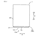
本実施例の金属製箱体1は、図1に示すように、金属板からなる底部10と、底部10の外周縁11から立設した金属板からなる側壁部20とを有する。
底部10と側壁部20との境界部分30は、両者を溶接してなる溶接部31を含む。
溶接部31は、金属製箱体1における側壁部20の立設方向下方Z1の表面10aに表出している。
そして、図2に示すように、底部10における側壁部20の立設方向下方Z1の端部である下端部12は、溶接部31よりも立設方向下方Z1に位置している。
上記金属製箱体の実施例について、図1~図5を用いて説明する。
本実施例の金属製箱体1は、図1に示すように、金属板からなる底部10と、底部10の外周縁11から立設した金属板からなる側壁部20とを有する。
底部10と側壁部20との境界部分30は、両者を溶接してなる溶接部31を含む。
溶接部31は、金属製箱体1における側壁部20の立設方向下方Z1の表面10aに表出している。
そして、図2に示すように、底部10における側壁部20の立設方向下方Z1の端部である下端部12は、溶接部31よりも立設方向下方Z1に位置している。
以下、本実施例の金属製箱体1について、詳述する。
本実施例の金属製箱体1を形成する材料は金属材料であって、金属製箱体1に収容する収容物の性質、金属製箱体1の使用環境、形成材料の成形性などを考慮して適宜選択することができる。例えば、電池のケースとして使用する場合は、耐腐食性や溶接性などを考慮してステンレス鋼、鉄鋼、チタン、チタン合金、アルミニウム、アルミニウム合金などとすることができる。
本実施例の金属製箱体1を形成する材料は金属材料であって、金属製箱体1に収容する収容物の性質、金属製箱体1の使用環境、形成材料の成形性などを考慮して適宜選択することができる。例えば、電池のケースとして使用する場合は、耐腐食性や溶接性などを考慮してステンレス鋼、鉄鋼、チタン、チタン合金、アルミニウム、アルミニウム合金などとすることができる。
金属製箱体1の外形形状は、特に限定されず、底部10の形状を矩形、円、楕円、長方形の短辺を円弧状にした形状、又は矩形の角部に丸みをつけた形状などとすることができる。そして、側壁部20は底部10の外周縁に立設させた形状とする。
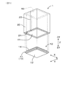
本例では、金属製箱体1は、図1に示すように、略直方体形状であって、底部10と側壁部20を備える。底部10の反対側は開放されており、開口部40が形成されている。本例では、図3に示すように、底部10と側壁部20とは、互いに別体として成形されたものを溶接して一体化される。底部10は略平板状をなしており、平面視で矩形となっている。そして、底部10の面方向のうち底部10の一辺に平行な方向を幅方向Xとし、底部10の面方向のうち幅方向Xに直交する方向を奥行き方向Yとする。そして、側壁部20は筒状であって側壁部20の底面の外形は四角形をなしており、底部10の各辺から側壁部20が立設されている。側壁部20の立設方向Zは幅方向Xと奥行き方向Yとに直交する方向である。
本例では、図3に示すように、側壁部20は、金属板を筒状に折り曲げて端部同士を突き当てた状態で溶接することにより成形される。これにより、側壁溶接部22が形成される。本例では、側壁溶接部22は、側壁部20の角部23に位置しないように構成されている。そして、側壁部20の側壁下端部21は四角形状に開口した下端開口部41を形成している。
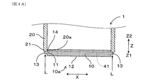
底部10の外周縁11には、図3に示すように、フランジ部13が設けられている。フランジ部13は底部10の外周縁11から底部10の面方向外方へ突出している。底部10の外周縁11にフランジ部13を形成する方法は特に限定されず、プレス加工、切削加工などとすることができる。そして、図5Aに示すように、底部10はフランジ部13が側壁部20の下端である側壁下端部21の下端面21aに当接するように側壁部20である側壁下端部21にあてがわれ、図4Aに示すように、図面における立設方向Zの下側から立設方向上方Z2に向けて矢印Lで示すようにレーザを照射して、フランジ部13と側壁下端部21とを溶接して溶接部31が形成されている。レーザを照射する方向は立設方向Zに平行な方向に限らず、金属製箱体1の斜め下方の位置からフランジ部13に向かう方向であってもよい。なお、各図において、レーザを照射する方向は図面の下方から上方に向かう方向としているが、実際には上下反転させて重力方向の上方から下方に向かう方向とする。また、溶接方法は限定されず、レーザ溶接に替えて、TIG溶接などとしてもよい。
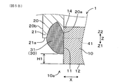
図4Bに示すように、溶接部31は、金属製箱体1の立設方向下方Z1の表面10aに表出している。本例では、境界部分30の全体が溶接部31となっている。そして、溶接部31は溶接ビードをなしており、図1に示すように、底部10の外縁に沿って全周方向に形成されて、全体において不揃いな形状となっている。本例では、図4Bに示すように、幅方向Xにおいて、側壁部20の外周面20bよりも内側に位置している。
そして、図5Bに示すように、下端部12は、立設方向Zにおいて、溶接部31よりも高さH1の分、立設方向下方Z1に位置している。高さH1は例えば、0.2~5.0mmの範囲内とすることができ、本例では、0.2~1.0mmの範囲内としている。
図4Aに示すように、底部10は側壁部20の下端開口部41に入り込んで、側壁部20の内周面20aに当接する内周当接部14を備える。内周当接部14は、側壁部20の内周面20aにおいて、少なくとも互いに対向する一対の面にそれぞれ当接するように構成されており、本例では内周当接部14は内周面20aの4面すべてに当接している。
金属製箱体1を形成する金属材料の厚さは、特に限定されないが、約0.1mm~約2.0mmとすることができる。本例では、図5Aに示すように、底部10の厚さT1は1.5mmであり、側壁部20の厚さT2は1.0mmである。そして、フランジ部13の厚さT3は0.5mm以上で底部10の厚さT1未満とすることができ、本例では厚さT3は0.5mmである。すなわち、フランジ部13は、底部10の中央部よりも薄肉に形成されている。そして、フランジ部13の幅W、すなわち下端部12とフランジ部13との段差部15の幅方向Xの長さWは、0.5mm以上で側壁部20の厚さT2未満とすることができ、本例では幅Wは0.8mmである。
また、図5Aに示すように、下端部12とフランジ部13との立設方向Zにおける距離T4、すなわち、下端部12とフランジ部13との段差部15の深さT4は0.5mm以上で底部10の厚さT1未満とすることができ、本例では厚さT3は0.5mmである。そして、内周当接部14の立設方向Zにおけるフランジ部13からの厚さT5は0.5mm以上で底部10の厚さT1未満とすることができ、本例では厚さT5は0.5mmである。
本例の金属製箱体1の作用効果について説明する。
本例の金属製箱体1においては、底部10とその外周縁11から立設した側壁部20との境界部分30に含まれる溶接部31は側壁部20の立設方向下方Z1の表面10aに表出しているが、底部10が溶接部31よりも立設方向下方Z1に位置する下端部12を有しているため、立設方向下方Z1から溶接して溶接部31を形成したとしても、溶接部31に含まれる不揃いな形状の溶接ビードが底部10の下端部12から立設方向下方Z1に突出することがない。そのため、金属製箱体1を載置面に載置すると底部10の下端部12が載置面に当接して、溶接部31の溶接ビードが載置面に当接しない。これにより、溶接作業性がよいとともに、金属製箱体1を安定して載置することができる。
本例の金属製箱体1においては、底部10とその外周縁11から立設した側壁部20との境界部分30に含まれる溶接部31は側壁部20の立設方向下方Z1の表面10aに表出しているが、底部10が溶接部31よりも立設方向下方Z1に位置する下端部12を有しているため、立設方向下方Z1から溶接して溶接部31を形成したとしても、溶接部31に含まれる不揃いな形状の溶接ビードが底部10の下端部12から立設方向下方Z1に突出することがない。そのため、金属製箱体1を載置面に載置すると底部10の下端部12が載置面に当接して、溶接部31の溶接ビードが載置面に当接しない。これにより、溶接作業性がよいとともに、金属製箱体1を安定して載置することができる。
また、本例では、底部10の外周縁11は、底部10の下端部12よりも立設方向上方Z2に位置するフランジ部13を有しており、フランジ部13と側壁部20とが互いに溶接されて溶接部31を形成している。これにより、フランジ部13を溶接する際のガイドとして利用することができ、溶接の作業性が向上する。
また、本例では、フランジ部13は、底部10の外周縁11を底部10の中央部よりも薄肉に形成されている。これにより、フランジ部13を底部10の下端部12よりも立設方向上方Z2に位置させることが容易となり、フランジ部13の成形の作業性が向上する。
また、本例では、下端部12は、側壁部20の立設方向Zにおいて、溶接部31よりも0.2~5.0mmの範囲内で立設方向下方Z1に位置している。これにより、金属製箱体1を載置したときに溶接部31の溶接ビードが載置面に当接しないとともに、金属製箱体1の底部10が立設方向Zに過度に厚くなることを抑制できる。
また、本例では、底部10は、側壁部20の内周面20aに当接する内周当接部14を有する。これにより、底部10を側壁部20に溶接する際に、底部10の位置決めが容易となり溶接時の作業性が向上する。
なお、本例では、底部10が内周当接部14を有することとしたが、これに替えて、図6A、図6Bに示す変形例1のように、底部10が内周当接部14を有しない構成であってもよい。
なお、本例では、フランジ部13が側壁部20の側壁下端部21の下端面21aに当接することとしたが、この構成に替えて、図7A、図7Bに示す変形例2のように、底部10の一部が側壁部20の下端開口部41内に入り込んでフランジ部13が側壁部20の内周面20aに当接する構成であってもよい。
さらなる変形例3として、変形例2の構成において、図8A、図8Bに示すように、側壁部20における下端開口部41近傍の内周面20aに突起24が突出形成されていてもよい。当該変形例3によれば、フランジ部13を突起24に当接させることにより、立設方向Zにおける底部10の位置決めを容易に行うことができる。
さらなる変形例4として、図9A、図9Bに示すように、フランジ部13の先端を立設方向下方Z1側に屈曲させた構成であってもよい。当該変形例4では、フランジ部13の先端の内側に凹部16が形成されており、フランジ部13の先端面13aを側壁部20の下端面21aと面一にした状態で溶接を行っている。なお、当該変形例4においても、図8A、図8Bに示す変形例3と同様に突起24が突出形成されていてもよい。
以上のごとく、本実施例1及び変形例1~4によれば、溶接時の作業性がよく、載置面に安定して載置可能な金属製箱体1を提供することができる。
(実施例2)
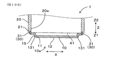
本例の金属製箱体1では、図10に示すように、底部10において中央部18の厚さT1と、フランジ部13の厚さT3が同じ厚さとなっており、ともに1.0mmとなっている。底部10は金属板をプレス加工して、外周縁11を立設方向上方Z2側に折り曲げて段差部15を形成してフランジ部13を形成している。これにより、フランジ部13は、立設方向上方Z2に折れ曲がるとともに、底部10の平面視における外方である幅方向X及び奥行き方向Yに折れ曲がった屈曲部131を有する。なお、本例において、実施例1と同様の構成には同一の符号を付して、その説明を省略する。
本例の金属製箱体1では、図10に示すように、底部10において中央部18の厚さT1と、フランジ部13の厚さT3が同じ厚さとなっており、ともに1.0mmとなっている。底部10は金属板をプレス加工して、外周縁11を立設方向上方Z2側に折り曲げて段差部15を形成してフランジ部13を形成している。これにより、フランジ部13は、立設方向上方Z2に折れ曲がるとともに、底部10の平面視における外方である幅方向X及び奥行き方向Yに折れ曲がった屈曲部131を有する。なお、本例において、実施例1と同様の構成には同一の符号を付して、その説明を省略する。
本例の金属製箱体1によれば、屈曲部131を有することにより、フランジ部13を簡易な構成で底部10の下端部12よりも立設方向上方Z2に位置させることができ、フランジ部13の成形性が向上する。そして、本例においても、実施例1の場合と同等の作用効果を奏する。
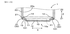
なお、図11A、図11Bに示す変形例5のように、実施例2の構成における底部10に、側壁部20の内周面20aに当接する内周当接部14を設けてもよい。当該内周当接部14は実施例1の場合と同様の構成とすることができる。
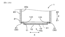
また、図12A、図12Bに示す変形例6のように、実施例2の構成における底部10の一部が側壁部20の下端開口部41内に入り込んでフランジ部13が側壁部20の内周面20aに当接する構成であってもよい。
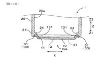
また、さらなる変形例7として、変形例6の構成において、図13A、図13Bに示すように側壁部20における下端開口部41近傍の内周面20aに突起24が突出形成されていてもよい。当該変形例7によれば、フランジ部13を突起24に当接させることにより、立設方向Zにおける底部10の位置決めを容易に行うことができる。
また、変形例8として、図14A、図14Bに示すように、実施例2の構成におけるフランジ部13の先端を立設方向下方Z1側に屈曲させた構成であってもよい。当該変形例8では、フランジ部13の先端の内側に凹部16が形成されており、フランジ部13の先端面13aを側壁部20の下端面21aと面一にした状態で溶接を行っている。なお、当該変形例8においても、図13A、図13Bに示す変形例7と同様に突起24が突出形成されていてもよい。
また、さらなる変形例9として、図15A、図15Bに示すように、底部10を平板状とするとともに、底部10の下端部12として、底部10から立設方向下方Z1に突出する突出部121を設けてもよい。本例では、突出部121は、底部10の外周縁11の内側の位置に外周縁11に沿って全周に形成されている。突出部121の高さは特に限定されず、例えば、0.5~2.0mmの範囲内とすることができる。そして、底部10の外周縁11の端面11aが側壁部20の内周面20aに当接した状態で両者が底部10の下方から立設方向上方Z2に向けて溶接されている。なお、突出部121を全周に形成することに替えて、底部10の四隅にそれぞれ設けてもよい。また、当該変形例9においても、図13A、図13Bに示す変形例7と同様に突起24が突出形成されていてもよい。
本変形例9の金属製箱体1では、図15A、図15Bに示すように、底部10の下端部12は、立設方向下方Z1に突出してなる突出部121からなる。これにより、金属製箱体1を載置面に載置したときに底部10の下端部12としての突出部121が確実に載置面に当接することとなるため、溶接部31が載置面に当接することとを確実に防止でき、当該金属製箱体1を載置した際の安定性を一層向上できる。
実施例1の場合と同様に、本実施例2及び変形例5~9によっても、溶接時の作業性がよく、載置面に安定して載置可能な金属製箱体1を提供することができる。
(実施例3)
また、実施例2では、底部10と側壁部20とを別体として用意し、両者を溶接にて接続したが、この構成に替えて、実施例3では図16Aに示すように、溶接前の金属製箱体の展開体1aにおいて、底部10と側壁部20とが一つながりの金属板からなり、底部10の一辺が折り曲げ部32を介して側壁部20と繋がっている。そして、図16Bに示すように、底部10は、折り曲げ部32で折り曲げるとともに、フランジ部13を側壁部20の側壁下端部21に重ねて矢印Lで示すようにレーザを照射し、図16Cに示すように、底部10と側壁部20とを溶接して溶接部31を形成する。
また、実施例2では、底部10と側壁部20とを別体として用意し、両者を溶接にて接続したが、この構成に替えて、実施例3では図16Aに示すように、溶接前の金属製箱体の展開体1aにおいて、底部10と側壁部20とが一つながりの金属板からなり、底部10の一辺が折り曲げ部32を介して側壁部20と繋がっている。そして、図16Bに示すように、底部10は、折り曲げ部32で折り曲げるとともに、フランジ部13を側壁部20の側壁下端部21に重ねて矢印Lで示すようにレーザを照射し、図16Cに示すように、底部10と側壁部20とを溶接して溶接部31を形成する。
図16Cに示すように、本実施例の金属製箱体1は、底部10と側壁部20との境界部分30は、溶接部31と折り曲げ部32とを含む。そして、境界部分30のうちの溶接部31は底部10の下端部12よりも立設方向上方Z2に位置するため、実施例1、2の場合と同等の作用効果を奏する。
本発明は上記各実施例及び変形例に限定されるものではなく、その要旨を逸脱しない範囲において種々の実施形態に適用することが可能である。
Claims (7)
- 金属板からなる底部と、該底部の外周縁から立設した金属板からなる側壁部とを有する金属製箱体であって、
上記底部と上記側壁部との境界部分は、両者を溶接してなる溶接部を含み、
該溶接部は、上記金属製箱体における上記側壁部の立設方向下方の表面に表出しており、
上記底部は、上記溶接部よりも上記立設方向下方に位置する下端部を有する、金属製箱体。 - 上記底部の外周縁は、上記底部の下端部よりも上記側壁部の立設方向上方に位置するフランジ部を有しており、該フランジ部と上記側壁部とが互いに溶接されて上記溶接部を形成している、請求項1に記載の金属製箱体。
- 上記フランジ部の厚さは、上記底部の中央部の厚さよりも薄くなっている、請求項2に記載の金属製箱体。
- 上記フランジ部は、上記立設方向上方に折れ曲がるとともに、上記底部の平面視における外方に折れ曲がった屈曲部を有する、請求項2に記載の金属製箱体。
- 上記下端部は、上記側壁部の立設方向において、上記溶接部よりも0.2~5.0mmの範囲内で上記立設方向下方に位置している、請求項1~4のいずれか一項に記載の金属製箱体。
- 上記下端部は、上記立設方向下方に突出してなる突出部からなる、請求項1~5のいずれか一項に記載の金属製箱体。
- 上記底部は、上記側壁部の内周面に当接する内周当接部を有する、請求項1~6のいずれか一項に記載の金属製箱体。
Priority Applications (4)
| Application Number | Priority Date | Filing Date | Title |
|---|---|---|---|
| KR1020217000626A KR102364557B1 (ko) | 2019-04-10 | 2020-01-09 | 금속 상자체 |
| EP20786687.2A EP3797923B1 (en) | 2019-04-10 | 2020-01-09 | Metal box body |
| US16/634,636 US11261004B2 (en) | 2019-04-10 | 2020-01-09 | Metal case |
| CN202080004063.8A CN112469530B (zh) | 2019-04-10 | 2020-01-09 | 金属制箱体 |
Applications Claiming Priority (2)
| Application Number | Priority Date | Filing Date | Title |
|---|---|---|---|
| JP2019075133A JP6862007B2 (ja) | 2019-04-10 | 2019-04-10 | 金属製箱体 |
| JP2019-075133 | 2019-04-10 |
Publications (1)
| Publication Number | Publication Date |
|---|---|
| WO2020208887A1 true WO2020208887A1 (ja) | 2020-10-15 |
Family
ID=72751610
Family Applications (1)
| Application Number | Title | Priority Date | Filing Date |
|---|---|---|---|
| PCT/JP2020/000384 Ceased WO2020208887A1 (ja) | 2019-04-10 | 2020-01-09 | 金属製箱体 |
Country Status (6)
| Country | Link |
|---|---|
| US (1) | US11261004B2 (ja) |
| EP (1) | EP3797923B1 (ja) |
| JP (1) | JP6862007B2 (ja) |
| KR (1) | KR102364557B1 (ja) |
| CN (1) | CN112469530B (ja) |
| WO (1) | WO2020208887A1 (ja) |
Cited By (1)
| Publication number | Priority date | Publication date | Assignee | Title |
|---|---|---|---|---|
| US20230408221A1 (en) * | 2022-06-15 | 2023-12-21 | Kenneth Frankel | Method for making a gun frame by high energy beam welding complementary metal frames along a common sagittal plane |
Families Citing this family (2)
| Publication number | Priority date | Publication date | Assignee | Title |
|---|---|---|---|---|
| JP6942870B2 (ja) * | 2017-07-07 | 2021-09-29 | Tvs Regza株式会社 | 受信装置 |
| US20260011831A1 (en) * | 2022-10-27 | 2026-01-08 | Lg Energy Solution, Ltd. | Welding Structure of Battery Can and Cap, and Battery Cell Having the Same Applied Thereto |
Citations (8)
| Publication number | Priority date | Publication date | Assignee | Title |
|---|---|---|---|---|
| JPH01130261U (ja) * | 1988-02-29 | 1989-09-05 | ||
| JP3057691U (ja) * | 1999-04-30 | 1999-06-02 | 泰和 楊 | 蓄電池 |
| JP2001236929A (ja) | 2000-02-22 | 2001-08-31 | Sumitomo Metal Ind Ltd | チタン製電池ケース |
| JP2004207333A (ja) * | 2002-12-24 | 2004-07-22 | Mitsubishi Paper Mills Ltd | セパレータ及びそれを用いてなる巻回型電気二重層キャパシタ |
| JP2014192054A (ja) * | 2013-03-27 | 2014-10-06 | Gs Yuasa Corp | 蓄電素子及び蓄電装置 |
| JP2015011948A (ja) * | 2013-07-02 | 2015-01-19 | 日立オートモティブシステムズ株式会社 | 電池及び電池の製造方法 |
| JP2015117610A (ja) * | 2013-12-18 | 2015-06-25 | カルソニックカンセイ株式会社 | コンバータおよびコンバータ組立体の製造方法 |
| JP2016045172A (ja) * | 2014-08-26 | 2016-04-04 | 株式会社不二工機 | 圧力センサ |
Family Cites Families (24)
| Publication number | Priority date | Publication date | Assignee | Title |
|---|---|---|---|---|
| US829477A (en) * | 1905-05-24 | 1906-08-28 | American Steel Package Company | Metallic barrel. |
| US3586204A (en) * | 1969-07-25 | 1971-06-22 | Wallace Expanding Machines | Container and method of making same |
| JPS55144654A (en) * | 1979-04-24 | 1980-11-11 | Uradeimirofuna Andoron Mariina | Alkaline storage battery |
| US4779751A (en) * | 1987-04-06 | 1988-10-25 | Thomas Munroe | Knock-down containers, container fastening system and elements thereof |
| US4813592A (en) * | 1988-05-26 | 1989-03-21 | International Precision Components Corporation | Sealing closure for lined drums |
| US4890786A (en) * | 1988-10-11 | 1990-01-02 | Sonoco Products Company | Fibre drum with reinforcement collar |
| US4951833B1 (en) * | 1989-03-10 | 1994-11-01 | Greif Bros | End construction with hollow beam construction for a drum |
| US6109052A (en) * | 1997-06-19 | 2000-08-29 | Austin, Jr.; Albert A. | Container, panel and method of forming thereof |
| JPH11219688A (ja) | 1998-02-02 | 1999-08-10 | Fuji Elelctrochem Co Ltd | 角形電気化学素子用の外装容器およびその外装容器を用いた角形電気化学素子の製造方法 |
| JP3720638B2 (ja) * | 1999-07-21 | 2005-11-30 | 太陽シールパック株式会社 | ファイバードラム、その筒状本体、および筒状本体の製造方法 |
| JP2002170550A (ja) * | 2000-11-30 | 2002-06-14 | Yuasa Corp | 密閉形鉛蓄電池 |
| DE10201362C1 (de) * | 2002-01-16 | 2003-10-16 | Dornier Gmbh | Container |
| BRPI0512117A (pt) * | 2004-06-17 | 2008-02-06 | Crebocan Ag | processo para a produção de um corpo de cápsula, bem como corpo de cápsula |
| JP4789434B2 (ja) * | 2004-06-30 | 2011-10-12 | 三洋電機株式会社 | 密閉型電池及びその製造方法 |
| JP4537278B2 (ja) * | 2005-07-15 | 2010-09-01 | 株式会社日立産機システム | タンクの底板構造 |
| US8123061B1 (en) * | 2007-03-26 | 2012-02-28 | Charles Kenneth Brown | Refuse container |
| JP5504007B2 (ja) | 2010-02-26 | 2014-05-28 | 日立ビークルエナジー株式会社 | 角形電池およびその製造方法 |
| JP2012060052A (ja) * | 2010-09-13 | 2012-03-22 | Panasonic Corp | 蓄電装置 |
| JP6064434B2 (ja) * | 2012-08-20 | 2017-01-25 | 株式会社Gsユアサ | 電池 |
| JP5733287B2 (ja) | 2012-10-19 | 2015-06-10 | トヨタ自動車株式会社 | 密閉型電池の圧力型電流遮断装置 |
| KR20140105927A (ko) * | 2013-02-25 | 2014-09-03 | (주)건영통상 | 변압기용 케이스 |
| WO2015072010A1 (ja) * | 2013-11-15 | 2015-05-21 | 日立オートモティブシステムズ株式会社 | 角形電池 |
| JP6213784B2 (ja) * | 2015-06-12 | 2017-10-18 | トヨタ自動車株式会社 | 密閉型電池 |
| CN207637925U (zh) | 2017-12-27 | 2018-07-20 | 东莞市振洋新能源科技有限公司 | 一种锂电池 |
-
2019
- 2019-04-10 JP JP2019075133A patent/JP6862007B2/ja active Active
-
2020
- 2020-01-09 KR KR1020217000626A patent/KR102364557B1/ko active Active
- 2020-01-09 CN CN202080004063.8A patent/CN112469530B/zh active Active
- 2020-01-09 US US16/634,636 patent/US11261004B2/en active Active
- 2020-01-09 WO PCT/JP2020/000384 patent/WO2020208887A1/ja not_active Ceased
- 2020-01-09 EP EP20786687.2A patent/EP3797923B1/en active Active
Patent Citations (8)
| Publication number | Priority date | Publication date | Assignee | Title |
|---|---|---|---|---|
| JPH01130261U (ja) * | 1988-02-29 | 1989-09-05 | ||
| JP3057691U (ja) * | 1999-04-30 | 1999-06-02 | 泰和 楊 | 蓄電池 |
| JP2001236929A (ja) | 2000-02-22 | 2001-08-31 | Sumitomo Metal Ind Ltd | チタン製電池ケース |
| JP2004207333A (ja) * | 2002-12-24 | 2004-07-22 | Mitsubishi Paper Mills Ltd | セパレータ及びそれを用いてなる巻回型電気二重層キャパシタ |
| JP2014192054A (ja) * | 2013-03-27 | 2014-10-06 | Gs Yuasa Corp | 蓄電素子及び蓄電装置 |
| JP2015011948A (ja) * | 2013-07-02 | 2015-01-19 | 日立オートモティブシステムズ株式会社 | 電池及び電池の製造方法 |
| JP2015117610A (ja) * | 2013-12-18 | 2015-06-25 | カルソニックカンセイ株式会社 | コンバータおよびコンバータ組立体の製造方法 |
| JP2016045172A (ja) * | 2014-08-26 | 2016-04-04 | 株式会社不二工機 | 圧力センサ |
Non-Patent Citations (1)
| Title |
|---|
| See also references of EP3797923A4 |
Cited By (1)
| Publication number | Priority date | Publication date | Assignee | Title |
|---|---|---|---|---|
| US20230408221A1 (en) * | 2022-06-15 | 2023-12-21 | Kenneth Frankel | Method for making a gun frame by high energy beam welding complementary metal frames along a common sagittal plane |
Also Published As
| Publication number | Publication date |
|---|---|
| JP6862007B2 (ja) | 2021-04-21 |
| CN112469530B (zh) | 2022-04-01 |
| JP2020172295A (ja) | 2020-10-22 |
| KR20210011058A (ko) | 2021-01-29 |
| CN112469530A (zh) | 2021-03-09 |
| US20210237930A1 (en) | 2021-08-05 |
| US11261004B2 (en) | 2022-03-01 |
| EP3797923A4 (en) | 2021-09-29 |
| EP3797923B1 (en) | 2025-02-19 |
| EP3797923A1 (en) | 2021-03-31 |
| KR102364557B1 (ko) | 2022-02-23 |
Similar Documents
| Publication | Publication Date | Title |
|---|---|---|
| JP6862007B2 (ja) | 金属製箱体 | |
| US20180287102A1 (en) | Battery Cell Housing and Method for Producing Same | |
| JP2009120248A (ja) | 支持片付き包装体 | |
| JP2017042804A (ja) | 折曲げ加工方法 | |
| US20140302340A1 (en) | Sheet metal blank and method for producing a sheet metal component having a laser-welding-compliant triangular corner | |
| JP2016193760A (ja) | シールエンドカートン | |
| JP2015061433A (ja) | キャビネット | |
| JP4600115B2 (ja) | オイルパン装置 | |
| JP7126426B2 (ja) | ブリスター包装容器 | |
| JP4947496B2 (ja) | 金属製容器及びその製造方法 | |
| JP5559601B2 (ja) | 金属板製道具箱 | |
| JP2020203291A (ja) | 曲げ加工品及びその製造方法 | |
| JP7487442B2 (ja) | レーザー裁断装置 | |
| JP2017007735A (ja) | 梱包用緩衝材 | |
| JP4613868B2 (ja) | 金属製深底容器及びその製造方法 | |
| JP6756499B2 (ja) | 容器 | |
| JP2019182467A (ja) | 段ボール箱 | |
| JP2015063897A5 (ja) | ||
| CN217397339U (zh) | 烟机组件及其泡沫包装件 | |
| JP2014161874A (ja) | 金属製箱体及びその製造方法 | |
| JP5127566B2 (ja) | 電気機器収納用箱 | |
| JP2025057105A (ja) | 金属板材の曲げ加工方法、及び、金属板材の曲げ加工品 | |
| JP2003132857A (ja) | 密閉型二次電池およびその製造方法 | |
| JPH0891439A (ja) | 包装装置 | |
| JP4909692B2 (ja) | 緩衝材シート及び容器入り箱体 |
Legal Events
| Date | Code | Title | Description |
|---|---|---|---|
| 121 | Ep: the epo has been informed by wipo that ep was designated in this application |
Ref document number: 20786687 Country of ref document: EP Kind code of ref document: A1 |
|
| ENP | Entry into the national phase |
Ref document number: 20217000626 Country of ref document: KR Kind code of ref document: A |
|
| ENP | Entry into the national phase |
Ref document number: 2020786687 Country of ref document: EP Effective date: 20201217 |
|
| NENP | Non-entry into the national phase |
Ref country code: DE |