WO2021001925A1 - Unité extérieure pour conditionneur d'air - Google Patents
Unité extérieure pour conditionneur d'air Download PDFInfo
- Publication number
- WO2021001925A1 WO2021001925A1 PCT/JP2019/026302 JP2019026302W WO2021001925A1 WO 2021001925 A1 WO2021001925 A1 WO 2021001925A1 JP 2019026302 W JP2019026302 W JP 2019026302W WO 2021001925 A1 WO2021001925 A1 WO 2021001925A1
- Authority
- WO
- WIPO (PCT)
- Prior art keywords
- soundproofing material
- outdoor unit
- compressor
- soundproofing
- surface portion
- Prior art date
- Legal status (The legal status is an assumption and is not a legal conclusion. Google has not performed a legal analysis and makes no representation as to the accuracy of the status listed.)
- Ceased
Links
Images


Classifications
-
- F—MECHANICAL ENGINEERING; LIGHTING; HEATING; WEAPONS; BLASTING
- F24—HEATING; RANGES; VENTILATING
- F24F—AIR-CONDITIONING; AIR-HUMIDIFICATION; VENTILATION; USE OF AIR CURRENTS FOR SCREENING
- F24F1/00—Room units for air-conditioning, e.g. separate or self-contained units or units receiving primary air from a central station
- F24F1/06—Separate outdoor units, e.g. outdoor unit to be linked to a separate room comprising a compressor and a heat exchanger
- F24F1/40—Vibration or noise prevention at outdoor units
Definitions
- the present invention relates to an outdoor unit of an air conditioner that reduces noise.
- the outdoor unit of an air conditioner is provided with an outer shell portion and a partition plate for partitioning the inside of the outer shell portion.
- a machine room is formed by a part of the outer shell and a partition plate.
- a compressor is housed in this machine room.
- the conventional outdoor unit is provided with a soundproofing material that surrounds the outer peripheral portion of the compressor.
- noise may leak from the soundproofing material that surrounds the outer periphery of the compressor.
- the noise leaking from the soundproofing material surrounding the outer peripheral portion of the compressor is, for example, the noise transmitted to the outside of the soundproofing material through the gap of the soundproofing material.
- the noise leaking from the soundproof material surrounding the outer peripheral portion of the compressor is generated when the compressor or the refrigerant pipe connected to the compressor comes into contact with the soundproof material and the vibration of the compressor is transmitted to the soundproof material. It's noise.
- a soundproofing material is provided at a portion constituting the machine room on the back surface of the outer shell, and noise leaked from the soundproofing material surrounding the outer peripheral portion of the compressor is emitted from the outdoor unit.
- a device that suppresses leakage to the outside has also been proposed (see Patent Document 1).
- the noise leaked from the soundproofing material that surrounds the outer periphery of the compressor is reflected by the partition plate that forms part of the machine room and propagates in a specific direction.
- the noise of the outdoor unit increases in the direction in which the noise reflected by the partition plate propagates. In order to suppress this noise, it is necessary to disperse the direction in which this noise propagates.
- the conventional outdoor unit which aims to suppress the noise leaked from the soundproofing material surrounding the outer peripheral portion of the compressor from leaking to the outside of the outdoor unit, it is provided outside the soundproofing material surrounding the outer peripheral portion of the compressor.
- the soundproofing material is provided on the back surface of the outer shell.
- the position of the soundproofing material provided on the back surface of the outer shell portion is far from the position where the noise leaked from the soundproofing material surrounding the outer peripheral portion of the compressor is reflected by the partition plate.
- the conventional outdoor unit which is designed to prevent the noise leaked from the soundproofing material surrounding the outer peripheral portion of the compressor from leaking to the outside of the outdoor unit, transmits the noise reflected by the partition plate and propagated in a specific direction. It cannot be sufficiently dispersed by the soundproofing material provided on the back surface of the outer shell.
- the present invention has been made to solve the above-mentioned problems, and an object of the present invention is to obtain an outdoor unit of an air conditioner capable of suppressing noise of an outdoor unit more than before.
- the outdoor unit of the air conditioner according to the present invention includes an outer shell portion, a partition plate for partitioning the inside of the outer shell portion, a compressor, and a first soundproofing material surrounding the outer peripheral portion of the compressor.
- a machine room is formed by a part of a portion and the partition plate, and the outdoor unit of an air conditioner in which the compressor is housed in the machine room, which is a plate-shaped second extending in the machine room in the vertical direction.
- a soundproofing material is further provided, and the second soundproofing material is provided with a non-woven fabric on the surface on the compressor side, and a portion of the outer shell portion constituting the front portion of the machine room is designated as the first front surface portion.
- the second soundproofing material is the first soundproofing material, the said.
- the first soundproofing material, the first front surface portion, the first side surface portion and the first back surface portion so as not to touch the first front surface portion, the first side surface portion and the first back surface portion. It is located in an enclosed space.
- the second soundproofing material provided outside the first soundproofing material surrounding the outer peripheral portion of the compressor is provided outside the soundproofing material surrounding the outer peripheral portion of the compressor.
- the noise leaked from the first soundproofing material is arranged at a position closer to the position where it is reflected on the partition plate. Therefore, in the outdoor unit of the air conditioner according to the present invention, the noise reflected by the partition plate and propagated in a specific direction can be dispersed by the second soundproofing material. Therefore, the outdoor unit according to the present invention can suppress the noise of the outdoor unit more than before.
- FIG. FIG. 5 is a perspective view of the outdoor unit according to the first embodiment as viewed from the front right side. It is a perspective view which looked at the outdoor unit which concerns on Embodiment 1 from the front right side, and is the figure which showed the state which the top surface part, the front part part, the left side side part part, the right side side part, and the back part of the outer shell part were removed. is there. It is a figure which observed the periphery of the compressor of the outdoor unit which concerns on Embodiment 1 from the side. It is a figure which observed the cross section of the machine room of the outdoor unit which concerns on Embodiment 1 from above.
- FIG. 1 It is a figure which observed the cross section of the machine room of the outdoor unit which concerns on Embodiment 2 from above. It is a figure which looked at the 2nd soundproofing material which concerns on Embodiment 3 from the side. It is a vertical sectional view of the 2nd soundproofing material which concerns on Embodiment 4.
- FIG. 1 It is a figure which observed the cross section of the machine room of the outdoor unit which concerns on Embodiment 2 from above. It is a figure which looked at the 2nd soundproofing material which concerns on Embodiment 3 from the side. It is a vertical sectional view of the 2nd soundproofing material which concerns on Embodiment 4.
- FIG. 1 is a refrigerant circuit diagram of an air conditioner in which the outdoor unit according to the first embodiment is used.
- the air conditioner 1 in which the outdoor unit 2 according to the first embodiment is used includes a refrigeration cycle circuit 10.
- the refrigeration cycle circuit 10 is configured by connecting a compressor 40, a four-way switching valve 11, an outdoor heat exchanger 12, an indoor heat exchanger 13, an expansion valve 14, and an expansion valve 15 with a refrigerant pipe.
- the type of refrigerant circulating in the refrigeration cycle circuit 10 is not limited.
- Various refrigerants such as R410A, R32, water and CO 2 can be used as the refrigerant circulating in the refrigeration cycle circuit 10.
- the compressor 40 compresses the refrigerant.
- the compressor 40 includes a main body 41 having a compression mechanism for compressing the refrigerant. Further, the main body 41 includes a container 42 which is a closed container. The compression mechanism unit is housed in the container 42. Further, the compressor 40 includes a suction muffler 43 which is a closed container. The suction muffler 43 separates the refrigerant flowing into the suction muffler 43 into a gaseous refrigerant and a liquid refrigerant. The refrigerant outlet of the suction muffler 43 is connected to the refrigerant inlet of the main body 41. Then, the gaseous refrigerant is supplied from the suction muffler 43 to the main body 41.
- This gaseous refrigerant is compressed by the compression mechanism of the main body 41 and then discharged from the main body 41. That is, the inflow port of the refrigerant of the suction muffler 43 is the suction port of the refrigerant of the compressor 40. Further, the outlet of the refrigerant of the main body 41, in other words, the outlet of the refrigerant of the container 42 is the discharge port of the refrigerant of the compressor 40.
- the refrigerant pipe connected to the refrigerant suction port of the compressor 40 will be referred to as the suction pipe 18.
- the suction pipe 18 is connected to the upper part of the suction muffler 43.
- the refrigerant pipe connected to the refrigerant discharge port of the compressor 40 will be referred to as a discharge pipe 19.
- the discharge pipe 19 is connected to the upper part of the container 42.
- the four-way switching valve 11 is connected to the refrigerant suction port of the compressor 40, the refrigerant discharge port of the compressor 40, the outdoor heat exchanger 12, and the indoor heat exchanger 13.
- the four-way switching valve 11 switches the connection destination of the refrigerant discharge port of the compressor 40 to the outdoor heat exchanger 12 or the indoor heat exchanger 13. In other words, the four-way switching valve 11 switches the connection destination of the refrigerant suction port of the compressor 40 to the outdoor heat exchanger 12 or the indoor heat exchanger 13.
- the outdoor heat exchanger 12 functions as an evaporator during the heating operation and as a condenser during the cooling operation.
- the fan 21 is provided in the vicinity of the outdoor heat exchanger 12.
- the fan 21 supplies the outdoor heat exchanger 12 with outdoor air that is a heat exchange target of the refrigerant flowing through the outdoor heat exchanger 12.
- the fan 21 is driven by a motor 22.
- the indoor heat exchanger 13 functions as a condenser during the heating operation and as an evaporator during the cooling operation.
- the expansion valve 14 is provided in the refrigerant pipe connecting the outdoor heat exchanger 12 and the indoor heat exchanger 13, and regulates the flow rate of the refrigerant flowing through the outdoor heat exchanger 12.
- the expansion valve 15 is provided at a position closer to the indoor heat exchanger 13 than the expansion valve 14 in the refrigerant pipe connecting the outdoor heat exchanger 12 and the indoor heat exchanger 13, and flows through the indoor heat exchanger 13. Adjust the flow rate of the refrigerant.
- the air conditioner 1 is provided with various sensors and a control device 38.
- the pressure sensor 31 detects the pressure of the refrigerant discharged from the compressor 40.
- the pressure sensor 32 detects the pressure of the refrigerant sucked into the compressor 40.
- the temperature sensor 33 detects the temperature of the outdoor air supplied to the outdoor heat exchanger 12.
- the temperature sensor 34 detects the temperature of the refrigerant flowing through the outdoor heat exchanger 12.
- the temperature sensor 35 detects the temperature of the refrigerant flowing between the expansion valve 15 and the indoor heat exchanger 13.
- the temperature sensor 36 detects the temperature of the refrigerant flowing through the indoor heat exchanger 13.
- the temperature sensor 37 detects the temperature of the indoor air supplied to the indoor heat exchanger 13.
- the control device 38 controls the drive frequency of the compression mechanism of the compressor 40, the rotation speed of the fan 21, the opening degree of the expansion valve 14, the opening degree of the expansion valve 15, and the like based on the detected values of these sensors. ..
- the outdoor unit 2 includes a four-way switching valve 11, an outdoor heat exchanger 12, an expansion valve 14, a fan 21, a motor 22, a pressure sensor 31, a pressure sensor 32, a temperature sensor 33, a temperature sensor 34, and a control device. 38 and the compressor 40 are housed in it.
- the indoor unit 3 houses an indoor heat exchanger 13, an expansion valve 15, a temperature sensor 35, a temperature sensor 36, and a temperature sensor 37. Further, in the air conditioner 1 according to the first embodiment, the refrigerant pipe connecting the configuration of the refrigeration cycle circuit 10 provided in the outdoor unit 2 and the configuration of the refrigeration cycle circuit 10 provided in the indoor unit 3 is connected.
- An on-off valve 16 and an on-off valve 17 are provided.
- the on-off valve 16 and the on-off valve 17 are housed in the outdoor unit 2.
- the air conditioner 1 according to the first embodiment includes two indoor units 3. These indoor units 3 are connected to the outdoor unit 2 in parallel.
- FIG. 2 is a perspective view of the outdoor unit according to the first embodiment as viewed from the front right side.
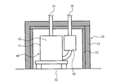
- FIG. 3 is a perspective view of the outdoor unit according to the first embodiment as viewed from the front right side, and shows the outdoor unit in a state where the top surface portion, the front surface portion, the left side surface portion, the right side surface portion, and the back surface portion of the outer shell portion are removed. It is a figure shown.
- the outdoor unit 2 includes, for example, an outer shell portion 50 having a substantially rectangular parallelepiped shape. Further, the outer shell portion 50 is provided with a plurality of handles 59 that the operator grips when moving the outdoor unit 2.
- the method of configuring the outer shell portion 50 is not particularly limited, but in the first embodiment, the top panel 51, the base 52, the front panel 53, the service panel 54, the right side panel 55, the left side panel 56, the cover panel 57, and the like.
- the cover panel 58 constitutes the outer shell portion 50.
- the top panel 51 constitutes the top of the outer shell 50.
- the base 52 constitutes a bottom surface portion of the outer shell portion 50.
- the front panel 53 constitutes a left side portion of the front surface portion of the outer shell portion 50.
- the service panel 54 constitutes an upper portion on the right side of the front surface portion of the outer shell portion 50 and an upper portion on the front side of the right side surface portion of the outer shell portion 50.
- the right side panel 55 constitutes an upper portion on the rear side of the right side surface portion of the outer shell portion 50 and an upper portion on the right side of the back surface portion of the outer shell portion 50.
- the left side panel 56 constitutes the left side surface of the outer shell 50.
- the cover panel 57 constitutes a lower portion on the right side of the front surface portion of the outer shell portion 50 and a lower portion on the front side of the right side surface portion of the outer shell portion 50.
- the cover panel 58 constitutes a lower portion on the rear side of the right side surface portion of the outer shell portion 50 and a lower portion on the right side of the back surface portion of the outer shell portion 50.
- the inside of the outer shell portion 50 is divided into a blower room 61 and a machine room 62 by a partition plate 60. That is, the machine room 62 is formed by a part of the outer shell portion 50 and the partition plate 60.
- the outdoor heat exchanger 12 is housed in the blower room 61.
- the fan 21 and the motor 22 are also housed in the blower chamber 61.
- the compressor 40 is housed in the machine room 62.
- the air conditioner 1 when the operation of the air conditioner is started and the compressor is driven, the compressor vibrates. Then, noise may be generated due to the vibration of this compressor. For this reason, some conventional air conditioners are provided with a soundproofing material that surrounds the outer peripheral portion of the compressor.
- the air conditioner 1 according to the first embodiment also includes a first soundproofing material 70 that surrounds the outer peripheral portion of the compressor 40.
- the first soundproofing material 70 has the same structure as the conventional soundproofing material.
- the first soundproofing material 70 is configured as follows.
- FIG. 4 is a side view of the periphery of the compressor of the outdoor unit according to the first embodiment.
- the first soundproofing material 70 is shown in cross section. The side and the upper side of the compressor 40 are surrounded by the first soundproofing material 70.
- the first soundproofing material 70 includes a rubber portion 71 made of rubber, which constitutes an outer shell portion. That is, the rubber portion 71 has rigidity that can maintain the shape of the outer shell portion and has sound insulation. Further, the first soundproofing material 70 is provided with a non-woven fabric 72 on the inner peripheral surface of the rubber portion 71, in other words, on the surface of the rubber portion 71 facing the compressor 40.
- the non-woven fabric 72 has a sound absorbing effect.
- noise may leak from the soundproofing material that surrounds the outer peripheral part of the compressor.
- the noise of the compressor leaks from the gap of the soundproofing material surrounding the outer peripheral portion of the compressor.
- the compressor or the refrigerant pipe connected to the compressor may come into contact with the soundproof material surrounding the outer peripheral portion of the compressor, and the vibration of the compressor may be transmitted to the soundproof material.
- noise is generated by the vibration of the soundproofing material surrounding the outer peripheral portion, and the noise leaks from the soundproofing material surrounding the outer peripheral portion of the compressor.
- the compressor or the refrigerant pipe connected to the compressor comes into contact with the soundproofing material surrounding the outer peripheral portion of the compressor due to an assembly error of the soundproofing material surrounding the outer peripheral portion of the compressor, an assembly error of the compressor, or the like.
- the compressor or the refrigerant pipe connected to the compressor may come into contact with the soundproof material surrounding the outer peripheral portion of the compressor due to deformation due to aged deterioration of the soundproofing material surrounding the outer peripheral portion of the compressor. ..
- the compressor or the refrigerant pipe connected to the compressor may come into contact with the soundproofing material surrounding the outer peripheral portion of the compressor. ..
- a soundproofing material is provided at a portion constituting the machine room on the back surface of the outer shell, and noise leaked from the soundproofing material surrounding the outer peripheral portion of the compressor is emitted from the outdoor unit.
- the noise leaked from the soundproofing material surrounding the outer peripheral portion of the compressor is reflected by the partition plate that forms a part of the machine room and propagates in a specific direction.
- the noise of the outdoor unit increases in the direction in which the noise reflected by the partition plate propagates. In order to suppress this noise, it is necessary to disperse the direction in which this noise propagates.
- the conventional outdoor unit which aims to suppress the noise leaked from the soundproofing material surrounding the outer peripheral portion of the compressor from leaking to the outside of the outdoor unit, it is provided outside the soundproofing material surrounding the outer peripheral portion of the compressor.
- the soundproofing material is provided on the back surface of the outer shell.
- the position of the soundproofing material provided on the back surface of the outer shell is far from the position where the noise leaked from the soundproofing material surrounding the outer peripheral portion of the compressor is reflected by the partition plate.
- the conventional outdoor unit which is designed to prevent the noise leaked from the soundproofing material surrounding the outer peripheral portion of the compressor from leaking to the outside of the outdoor unit, transmits the noise reflected by the partition plate and propagated in a specific direction. It cannot be sufficiently dispersed by the soundproofing material provided on the back surface of the outer shell.
- the conventional outdoor unit which is designed to prevent the noise leaked from the soundproofing material surrounding the outer peripheral portion of the compressor from leaking to the outside of the outdoor unit, when the noise leaks from the soundproofing material surrounding the outer peripheral portion of the compressor, The noise of the outdoor unit could not be sufficiently suppressed.
- the outdoor unit 2 includes a second soundproofing material 80 in the machine room 62.
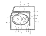
- FIG. 5 is a view of a cross section of the machine room of the outdoor unit according to the first embodiment observed from above.
- the lower side of the paper surface is the front side of the outdoor unit 2.
- FIG. 5 is a plan view of the inside of the machine room 62.
- the first front surface portion 63, the first side surface portion 64, and the first back surface portion 65 are defined as follows.
- the portion of the outer shell portion 50 that constitutes the front surface portion of the machine room 62 is referred to as the first front surface portion 63.
- the portion of the outer shell portion 50 that constitutes the side surface portion of the machine room 62 is referred to as the first side surface portion 64.
- the portion of the outer shell portion 50 that constitutes the back surface portion of the machine room 62 is referred to as the first back surface portion 65.
- the second soundproofing material 80 is a plate-shaped material extending in the vertical direction. Further, the second soundproofing material 80 is provided with a non-woven fabric 84 on the surface on the compressor 40 side. In other words, the second soundproofing material 80 is provided with the non-woven fabric 84 on the surface of the first soundproofing material 70 side. Then, the second soundproof material 80 does not touch the first soundproof material 70, the first front surface portion 63, the first side surface portion 64, and the first back surface portion 65, so that the partition plate 60, the first soundproof material 70, and the first soundproof material 80 are not touched. It is arranged in a space surrounded by a front surface portion 63, a first side surface portion 64, and a first back surface portion 65.
- the second soundproofing material 80 includes a first soundproofing section 81 and a second soundproofing section 82.
- the first soundproofing portion 81 is arranged between the first soundproofing material 70 and the first back surface portion 65.
- the end of the first soundproofing portion 81 on the partition plate 60 side is arranged in the vicinity of the partition plate 60. At this time, the end of the first soundproofing portion 81 on the partition plate 60 side may or may not be in contact with the partition plate 60. However, if the end of the first soundproofing portion 81 on the partition plate 60 side and the partitioning plate 60 are in contact with each other, noise will pass between the first soundproofing portion 81 and the partition plate 60 and the noise will be generated by the first back surface portion 65.
- the second soundproofing portion 82 is arranged between the first soundproofing material 70 and the first side surface portion 64.
- the end portion of the first soundproofing portion 81 on the second soundproofing portion 82 side and the end portion of the second soundproofing portion 82 on the first soundproofing portion 81 side are connected. That is, in the first embodiment, the second soundproofing material 80 has a substantially L-shape in a plan view.
- the main body 41 is arranged closer to the partition plate 60 than the suction muffler 43.
- the noise leaked from the first soundproofing material 70 surrounding the outer peripheral portion of the compressor 40 is reflected at the position A of the partition plate 60 and propagates in the specific direction indicated by the broken line arrow.
- This noise is dispersed between the first soundproofing material 70 and the first soundproofing portion 81 of the second soundproofing material 80 while being reflected by the first soundproofing material 70 and the first soundproofing portion 81. I will do it.
- the noise is absorbed by the non-woven fabric 84 on the surface of the first soundproofing portion 81 while being reflected by the first soundproofing material 70 and the first soundproofing portion 81.
- the noise is attenuated while being reflected by the first soundproofing material 70 and the first soundproofing material 70.
- the outdoor unit 2 according to the first embodiment includes the first soundproofing portion 81 of the second soundproofing material 80, the noise leaked from the first soundproofing material 70 leaks to the outside of the outdoor unit 2. This can be suppressed, and the noise of the outdoor unit 2 can be suppressed more than before.
- the noise leaked from the first soundproofing material 70 surrounding the outer peripheral portion of the compressor 40 is reflected by the partition plate 60 and heads toward the second soundproofing portion 82 of the second soundproofing material 80, the noise is generated.
- the first soundproofing material 70 and the second soundproofing part 82 reflect between the first soundproofing material 70 and the second soundproofing part 82 of the second soundproofing material 80.
- the direction of the noise is dispersed.
- the noise is absorbed by the non-woven fabric 84 on the surface of the second soundproofing portion 82 while being reflected by the first soundproofing material 70 and the second soundproofing portion 82.
- the noise is attenuated while being reflected by the first soundproofing material 70 and the second soundproofing unit 82.
- the outdoor unit 2 according to the first embodiment includes the second soundproofing portion 82 of the second soundproofing material 80, the noise leaked from the first soundproofing material 70 leaks to the outside of the outdoor unit 2. This can be suppressed, and the noise of the outdoor unit 2 can be suppressed more than before.
- the first soundproofing portion 81 arranged between the first soundproofing material 70 and the first back surface portion 65 absorbs and suppresses noise leaking from the first soundproofing material 70 toward the first back surface portion 65. You can also do it.
- the first soundproofing portion 81 is arranged at a position closer to the first soundproofing material 70 than the conventional soundproofing material. With a size smaller than that of the conventional soundproofing material, it is possible to obtain the same soundproofing effect as the conventional soundproofing material. That is, the first soundproofing unit 81 can obtain the same soundproofing effect as the conventional soundproofing material at a lower cost than the conventional soundproofing material.
- the second soundproofing portion 82 arranged between the first soundproofing material 70 and the first side surface portion 64 absorbs and suppresses the noise leaking from the first soundproofing material 70 toward the first side surface portion 64. You can also do it.
- the length of the first soundproofing portion 81 in the longitudinal direction is preferably longer than the length of the first soundproofing portion 81 in the first soundproofing material 70 in the longitudinal direction.
- the space between the first soundproofing material 70 and the first soundproofing portion 81 is longer in the longitudinal direction of the first soundproofing portion 81, the noise reflected by the first soundproofing material 70 and the first soundproofing portion 81 is further suppressed. Because it can be done. Further, it is possible to more reliably absorb the noise leaking from the first soundproofing material 70 toward the first back surface portion 65.
- the length of the second soundproofing portion 82 in the longitudinal direction is preferably longer than the length of the second soundproofing portion 82 in the first soundproofing material 70 in the longitudinal direction.
- the noise reflected by the first soundproof material 70 and the second soundproof portion 82 is further suppressed. Because it can be done. Further, it is possible to more reliably absorb the noise leaking from the first soundproofing material 70 toward the first side surface portion 64.
- the second soundproof material 80 includes the first soundproof part 81 and the second soundproof part 82, but the second soundproof material 80 is the first soundproof part 81 or the second soundproof part 82. It may have only one. As described above, the noise of the outdoor unit 2 can be suppressed more than before by using only one of the first soundproofing unit 81 and the second soundproofing unit 82.
- the outdoor unit 2 of the air conditioner 1 has the outer shell portion 50, the partition plate 60 for partitioning the inside of the outer shell portion 50, the compressor 40, and the outer peripheral portion of the compressor 40.
- the soundproofing material 70 is provided.
- a machine room 62 is formed by a part of the outer shell portion 50 and the partition plate 60, and the compressor 40 is housed in the machine room 62.
- the outdoor unit 2 according to the first embodiment further includes a plate-shaped second soundproofing material 80 extending in the vertical direction in the machine room 62.
- the second soundproofing material 80 is provided with a non-woven fabric 84 on the surface on the compressor 40 side.
- the second soundproof material 80 does not touch the first soundproof material 70, the first front surface portion 63, the first side surface portion 64, and the first back surface portion 65, so that the partition plate 60, the first soundproof material 70, and the first soundproof material 80 are not touched. It is arranged in a space surrounded by a front surface portion 63, a first side surface portion 64, and a first back surface portion 65.
- the second soundproofing material 80 provided outside the first soundproofing material 70 surrounding the outer peripheral portion of the compressor 40 is the outside of the soundproofing material surrounding the outer peripheral portion of the compressor.
- the noise leaking from the first soundproofing material 70 is arranged at a position closer to the position where the noise is reflected by the partition plate 60. Therefore, in the outdoor unit 2 according to the first embodiment, the noise reflected by the partition plate 60 and propagated in a specific direction can be dispersed by the second soundproofing material 80. Therefore, the outdoor unit 2 according to the first embodiment can suppress the noise of the outdoor unit 2 more than before.
- Embodiment 2 The outdoor unit 2 may be provided with a third soundproofing material 90 as described later in the machine room.
- a third soundproofing material 90 as described later in the machine room.
- items not particularly described are the same as those in the first embodiment, and the same functions and configurations as those in the first embodiment are described by using the same reference numerals.
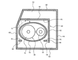
- FIG. 6 is a view of a cross section of the machine room of the outdoor unit according to the second embodiment observed from above.
- the outdoor unit 2 according to the second embodiment includes a third soundproofing material 90 in the machine room 62.
- the third soundproofing material 90 is a plate-shaped material extending in the vertical direction. Further, the third soundproofing material 90 is provided with a non-woven fabric 91 on the surface on the compressor 40 side. In other words, the third soundproofing material 90 is provided with the non-woven fabric 91 on the surface of the first soundproofing material 70 side.
- the third soundproofing material 90 is arranged between the partition plate 60 and the first soundproofing material 70.
- the third soundproofing material 90 is fixed to the partition plate 60 by, for example, adhesion or the like.
- the third soundproofing material 90 is also provided between the first soundproofing material 70, the second soundproofing portion 82 of the second soundproofing material 80, and the first front surface portion 63. It is provided.
- the third soundproofing material 90 is fixed to the second soundproofing portion 82 of the second soundproofing material 80, for example, by adhesion or the like.
- two third soundproofing materials 90 are provided in the machine room 62, but even if only one of the third soundproofing materials 90 is provided in the machine room 62, the outdoor area shown in the first embodiment is shown.
- the noise of the outdoor unit 2 can be further suppressed as compared with the machine 2.
- Embodiment 3 In the third embodiment, an example of a method for fixing the second soundproofing material 80 will be described. Further, in the third embodiment, an example of the shape of the second soundproofing material 80 will be described when there is a refrigerant pipe at the location where the second soundproofing material 80 is arranged.
- items not particularly described are the same as those of the first embodiment or the second embodiment, and the same reference numerals are used for the same functions and configurations as those of the first embodiment or the second embodiment. Will be described.
- FIG. 7 is a side view of the second soundproofing material according to the third embodiment.
- the second soundproofing material 80 according to the third embodiment includes at least one fixing portion 85 fixed to the partition plate 60 at the end portion on the partition plate 60 side.
- the method of fixing the fixing portion 85 and the partition plate 60 is not particularly limited.
- the fixing portion 85 and the partition plate 60 may be fixed by screws.
- a convex portion is provided on one of the fixed portion 85 and the partition plate 60, a concave portion on which the convex portion is hooked is provided on the other side of the fixed portion 85 and the partition plate 60, and the convex portion is hooked on the concave portion to partition the fixed portion 85.
- the plate 60 may be fixed.
- the fixing portion 85 on the second soundproofing material 80 By providing the fixing portion 85 on the second soundproofing material 80 in this way, it becomes easy to arrange the second soundproofing material 80 at a desired position. Further, by providing the fixing portion 85, the end portion of the second soundproofing material 80 on the partition plate 60 side can be arranged in the vicinity of the partition plate 60. Therefore, it is possible to suppress the noise from being transmitted to the first back surface portion 65 side through between the first soundproofing portion 81 and the partition plate 60, and the soundproofing effect of the outdoor unit 2 is improved.
- a refrigerant pipe 20 is provided at a position where the second soundproofing material 80 is arranged. Therefore, the second soundproofing material 80 is formed with a notch 86 and a notch 87 which are opened downward and into which the refrigerant pipe 20 is inserted. Since the notch 86 and the notch 87 are open downward, the second soundproofing material 80 can be lowered even if the refrigerant pipe 20 is present by lowering the second soundproofing material 80 from above the refrigerant pipe 20 to the installation position. It can be installed easily.
- the width of the notch 87 at a position below the refrigerant pipe 20 is smaller than the width at the height of the refrigerant pipe 20.
- Embodiment 4 an example of a specific structure of the second soundproofing material 80 will be described.
- the items not specifically described are the same as those of the first to third embodiments, and the same functions and configurations as those of the first to third embodiments are the same. It will be described using the code of.
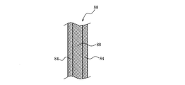
- FIG. 8 is a vertical sectional view of the second soundproofing material according to the fourth embodiment.
- the second soundproofing material 80 according to the fourth embodiment includes a supporting material 88 having a higher rigidity than the non-woven fabric 84.
- the support member 88 is made of, for example, rubber.
- the non-woven fabric 84 is provided on the surface of the support member 88. In FIG. 8, the non-woven fabric 84 is provided on both sides of the support member 88, but the non-woven fabric 84 may be provided at least on the surface on the compressor 40 side.
- the second soundproofing material 80 By configuring the second soundproofing material 80 in this way, it is possible to prevent the second soundproofing material 80 from falling under its own weight.
Landscapes
- Engineering & Computer Science (AREA)
- Chemical & Material Sciences (AREA)
- Combustion & Propulsion (AREA)
- Mechanical Engineering (AREA)
- General Engineering & Computer Science (AREA)
- Other Air-Conditioning Systems (AREA)
Abstract
L'unité extérieure pour conditionneur d'air de l'invention est équipée d'une partie contour, d'une plaque de séparation séparant une partie interne de ladite partie contour, d'un compresseur, et d'un premier matériau isolant acoustique entourant une partie périphérie externe dudit compresseur, et présente une chambre de machine formée par une partie de ladite partie contour et par ladite plaque de séparation, ledit compresseur étant stocké dans ladite chambre de machine. L'unité extérieure pour conditionneur d'air de l'invention est également équipée d'un second matériau isolant acoustique sous forme de plaque se prolongeant dans une direction verticale au niveau de la chambre de machine. Ledit second matériau isolant acoustique présente un tissu non-tissé agencé sur une surface côté compresseur. Lorsque dans ladite partie contour, une portion configurant une partie face avant de ladite chambre de machine constitue une première partie face avant, une portion configurant une partie face latérale de ladite chambre de machine constitue une première partie face latérale, et une portion configurant une partie face arrière de ladite chambre de machine constitue une première partie face arrière, ledit second matériau isolant acoustique est disposé dans un espace entouré par ladite plaque de séparation, ledit premier matériau isolant acoustique, ladite première partie face avant, ladite première partie face latérale et ladite première partie face arrière, de manière à ne pas être en contact avec ledit premier matériau isolant acoustique, ladite première partie face avant, ladite première partie face latérale et ladite première partie face arrière.
Priority Applications (3)
| Application Number | Priority Date | Filing Date | Title |
|---|---|---|---|
| PCT/JP2019/026302 WO2021001925A1 (fr) | 2019-07-02 | 2019-07-02 | Unité extérieure pour conditionneur d'air |
| CN201990000397.0U CN213841140U (zh) | 2019-07-02 | 2019-07-02 | 空调机的室外机 |
| JP2021529597A JP7118273B2 (ja) | 2019-07-02 | 2019-07-02 | 空気調和機の室外機 |
Applications Claiming Priority (1)
| Application Number | Priority Date | Filing Date | Title |
|---|---|---|---|
| PCT/JP2019/026302 WO2021001925A1 (fr) | 2019-07-02 | 2019-07-02 | Unité extérieure pour conditionneur d'air |
Publications (1)
| Publication Number | Publication Date |
|---|---|
| WO2021001925A1 true WO2021001925A1 (fr) | 2021-01-07 |
Family
ID=74100120
Family Applications (1)
| Application Number | Title | Priority Date | Filing Date |
|---|---|---|---|
| PCT/JP2019/026302 Ceased WO2021001925A1 (fr) | 2019-07-02 | 2019-07-02 | Unité extérieure pour conditionneur d'air |
Country Status (3)
| Country | Link |
|---|---|
| JP (1) | JP7118273B2 (fr) |
| CN (1) | CN213841140U (fr) |
| WO (1) | WO2021001925A1 (fr) |
Cited By (1)
| Publication number | Priority date | Publication date | Assignee | Title |
|---|---|---|---|---|
| WO2024218890A1 (fr) * | 2023-04-19 | 2024-10-24 | 三菱電機株式会社 | Unité extérieure de dispositif à cycle de réfrigération, et procédé pour la fabrication d'une unité extérieure de dispositif à cycle de réfrigération |
Citations (6)
| Publication number | Priority date | Publication date | Assignee | Title |
|---|---|---|---|---|
| JPS6028364U (ja) * | 1983-08-02 | 1985-02-26 | 三洋電機株式会社 | 空気調和機 |
| JPS62108726U (fr) * | 1985-12-26 | 1987-07-11 | ||
| JPH06288351A (ja) * | 1993-04-01 | 1994-10-11 | Idemitsu Petrochem Co Ltd | 防音ユニット |
| JPH0849883A (ja) * | 1994-08-05 | 1996-02-20 | Toshiba Corp | 空気調和機の室外機 |
| JPH1039875A (ja) * | 1996-07-19 | 1998-02-13 | Mitsubishi Heavy Ind Ltd | 遮音材構造および空気調和機の防音構造 |
| JP2011052842A (ja) * | 2009-08-31 | 2011-03-17 | Mitsubishi Electric Corp | ヒートポンプ室外機 |
Family Cites Families (2)
| Publication number | Priority date | Publication date | Assignee | Title |
|---|---|---|---|---|
| JPS5898571U (ja) * | 1981-12-25 | 1983-07-05 | 株式会社東芝 | 空気調和機 |
| CN108662681A (zh) * | 2018-07-21 | 2018-10-16 | 中环智创(北京)科技有限公司 | 一种空调及热泵外机降温消音器 |
-
2019
- 2019-07-02 JP JP2021529597A patent/JP7118273B2/ja not_active Expired - Fee Related
- 2019-07-02 CN CN201990000397.0U patent/CN213841140U/zh not_active Expired - Fee Related
- 2019-07-02 WO PCT/JP2019/026302 patent/WO2021001925A1/fr not_active Ceased
Patent Citations (6)
| Publication number | Priority date | Publication date | Assignee | Title |
|---|---|---|---|---|
| JPS6028364U (ja) * | 1983-08-02 | 1985-02-26 | 三洋電機株式会社 | 空気調和機 |
| JPS62108726U (fr) * | 1985-12-26 | 1987-07-11 | ||
| JPH06288351A (ja) * | 1993-04-01 | 1994-10-11 | Idemitsu Petrochem Co Ltd | 防音ユニット |
| JPH0849883A (ja) * | 1994-08-05 | 1996-02-20 | Toshiba Corp | 空気調和機の室外機 |
| JPH1039875A (ja) * | 1996-07-19 | 1998-02-13 | Mitsubishi Heavy Ind Ltd | 遮音材構造および空気調和機の防音構造 |
| JP2011052842A (ja) * | 2009-08-31 | 2011-03-17 | Mitsubishi Electric Corp | ヒートポンプ室外機 |
Non-Patent Citations (1)
| Title |
|---|
| 5 July 1983 (1983-07-05) * |
Cited By (3)
| Publication number | Priority date | Publication date | Assignee | Title |
|---|---|---|---|---|
| WO2024218890A1 (fr) * | 2023-04-19 | 2024-10-24 | 三菱電機株式会社 | Unité extérieure de dispositif à cycle de réfrigération, et procédé pour la fabrication d'une unité extérieure de dispositif à cycle de réfrigération |
| JPWO2024218890A1 (fr) * | 2023-04-19 | 2024-10-24 | ||
| JP7722478B2 (ja) | 2023-04-19 | 2025-08-13 | 三菱電機株式会社 | 冷凍サイクル装置の室外機及び冷凍サイクル装置の室外機の製造方法 |
Also Published As
| Publication number | Publication date |
|---|---|
| JP7118273B2 (ja) | 2022-08-15 |
| JPWO2021001925A1 (ja) | 2021-11-25 |
| CN213841140U (zh) | 2021-07-30 |
Similar Documents
| Publication | Publication Date | Title |
|---|---|---|
| EP3385626B1 (fr) | Machine extérieure | |
| US10760796B2 (en) | Outdoor unit of air-conditioning apparatus | |
| CN1329638C (zh) | 压缩机围罩 | |
| KR20140126644A (ko) | 항온항습기용 사일런트 실외기 | |
| JP7118273B2 (ja) | 空気調和機の室外機 | |
| KR100370014B1 (ko) | 공기조화기의 실외기의 소음 저감구조 | |
| JP3674417B2 (ja) | 空気調和装置の室内機 | |
| CN215175535U (zh) | 一种窗式空调器 | |
| US20250020373A1 (en) | Refrigeration cycle apparatus | |
| JP7134355B2 (ja) | 空気調和機の室外機 | |
| US20200232660A1 (en) | Unit for refrigeration cycle device, refrigeration cycle device, and electric apparatus | |
| JP6631706B2 (ja) | ヒートポンプ給湯室外機 | |
| JP7019097B2 (ja) | 空気調和機の室外機 | |
| KR102201761B1 (ko) | 실외기와 이를 포함하는 공기조화기 | |
| US20210010715A1 (en) | Environmental control unit including noise reduction features | |
| KR102396084B1 (ko) | 이동형 공기조화기 | |
| JP2017156038A (ja) | 防音カバー及びそれを備えた室外ユニット | |
| JP7684592B2 (ja) | 熱源ユニット及び冷凍サイクル装置 | |
| JP2008190724A (ja) | 床置型空気調和装置 | |
| KR100829135B1 (ko) | 공기조화기용 실내기의 소음 방지장치 | |
| KR102823665B1 (ko) | 공기조화기 | |
| KR20010037825A (ko) | 소음저감 창문형 에어컨 | |
| JP7663100B2 (ja) | 空気調和機の室外機 | |
| JP7695580B2 (ja) | 熱源ユニットおよび冷凍サイクル装置 | |
| JP3400242B2 (ja) | 温調庫機器 |
Legal Events
| Date | Code | Title | Description |
|---|---|---|---|
| 121 | Ep: the epo has been informed by wipo that ep was designated in this application |
Ref document number: 19936339 Country of ref document: EP Kind code of ref document: A1 |
|
| ENP | Entry into the national phase |
Ref document number: 2021529597 Country of ref document: JP Kind code of ref document: A |
|
| NENP | Non-entry into the national phase |
Ref country code: DE |
|
| 122 | Ep: pct application non-entry in european phase |
Ref document number: 19936339 Country of ref document: EP Kind code of ref document: A1 |