WO2021024423A1 - 軌条車両の異常検出装置 - Google Patents
軌条車両の異常検出装置 Download PDFInfo
- Publication number
- WO2021024423A1 WO2021024423A1 PCT/JP2019/031152 JP2019031152W WO2021024423A1 WO 2021024423 A1 WO2021024423 A1 WO 2021024423A1 JP 2019031152 W JP2019031152 W JP 2019031152W WO 2021024423 A1 WO2021024423 A1 WO 2021024423A1
- Authority
- WO
- WIPO (PCT)
- Prior art keywords
- rail vehicle
- detection device
- vehicle
- abnormality detection
- rail
- Prior art date
- Legal status (The legal status is an assumption and is not a legal conclusion. Google has not performed a legal analysis and makes no representation as to the accuracy of the status listed.)
- Ceased
Links
Images





Classifications
-
- G—PHYSICS
- G01—MEASURING; TESTING
- G01M—TESTING STATIC OR DYNAMIC BALANCE OF MACHINES OR STRUCTURES; TESTING OF STRUCTURES OR APPARATUS, NOT OTHERWISE PROVIDED FOR
- G01M17/00—Testing of vehicles
- G01M17/08—Railway vehicles
-
- B—PERFORMING OPERATIONS; TRANSPORTING
- B61—RAILWAYS
- B61L—GUIDING RAILWAY TRAFFIC; ENSURING THE SAFETY OF RAILWAY TRAFFIC
- B61L15/00—Indicators provided on the vehicle or train for signalling purposes
- B61L15/0081—On-board diagnosis or maintenance
-
- B—PERFORMING OPERATIONS; TRANSPORTING
- B61—RAILWAYS
- B61L—GUIDING RAILWAY TRAFFIC; ENSURING THE SAFETY OF RAILWAY TRAFFIC
- B61L27/00—Central railway traffic control systems; Trackside control; Communication systems specially adapted therefor
- B61L27/50—Trackside diagnosis or maintenance, e.g. software upgrades
- B61L27/57—Trackside diagnosis or maintenance, e.g. software upgrades for vehicles or trains, e.g. trackside supervision of train conditions
-
- G—PHYSICS
- G01—MEASURING; TESTING
- G01M—TESTING STATIC OR DYNAMIC BALANCE OF MACHINES OR STRUCTURES; TESTING OF STRUCTURES OR APPARATUS, NOT OTHERWISE PROVIDED FOR
- G01M7/00—Vibration-testing of structures; Shock-testing of structures
Definitions
- the present invention relates to an abnormality detection device for rail vehicles.
- CBM Condition Based Maintenance
- a detection device capable of detecting an abnormality related to vibration comfort and safety of a railway vehicle at an early stage and determining the cause of the abnormality is required.
- Patent Document 1 As such an abnormality detection device, for example, there is a technique disclosed in Patent Document 1.
- Patent Document 1 discloses an abnormality detection device that detects an abnormality in a bogie by using an acceleration of the bogie frame acquired by an acceleration sensor provided in the bogie frame and an acceleration of the wheel set acquired by an acceleration sensor provided in the wheel set. Has been done.
- the acceleration of the trolley is estimated by using a physical model that inputs the acceleration of the wheel set acquired by the acceleration sensor and outputs the acceleration of the trolley at the normal time. Then, it is possible to determine whether or not there is an abnormality in the bogie based on whether or not the estimated value of the acceleration and the actually measured value are close to each other.
- the abnormality detection device disclosed in Patent Document 1 it is necessary to provide acceleration sensors on both the wheel set and the bogie frame for one bogie in order to detect the abnormality of the bogie.
- the wheel sets and bogie frames generate vibration acceleration larger than that of the vehicle body, it is necessary to use an acceleration sensor having a high measurable range, which has led to an increase in installation cost.
- the wheel set and the bogie frame have less space for installing the acceleration sensor than the vehicle body, there is also a problem that the degree of freedom in installing the acceleration sensor is limited.
- the abnormality detection device disclosed in Patent Document 1 requires a large number of acceleration sensors, there are problems such as an increase in maintenance time and cost.
- the present invention has been made in view of the above-mentioned problems, and when an abnormal vibration of a vehicle occurs based on sensor information installed on a vehicle body while suppressing installation cost and maintenance cost, the vibration is generated in any part of the vehicle. It is an object of the present invention to provide an abnormality detection device for a rail vehicle capable of determining whether or not the abnormality is present.
- one of the representative abnormality detection devices for rail vehicles is a vibration data acquisition unit that acquires vibration data of the rail vehicle and operation data that acquires operation data of the rail vehicle. Based on the acquisition unit, the vibration data, and the operation data, it is identified whether the rail vehicle traveling on the same track is in a normal state or an abnormal state, and the vibration data of the rail vehicle is extracted in association with the normal state or the abnormal state.
- a comparison processing unit that calculates the comparison result by comparing the vibration data of the rail vehicle in the normal state with the vibration data of the rail vehicle in the abnormal state, and the abnormal state based on the comparison result. Achieved by having a diagnostic unit that determines anomalous causes of vibration in the identified rail vehicle.
- the present invention when an abnormal vibration of a vehicle occurs, it is possible to determine which part of the vehicle the vibration is abnormal based on the sensor information installed on the vehicle body while suppressing the installation cost and the maintenance cost. Anomaly detection device can be provided. In addition, this makes it possible to reduce vehicle downtime and maintenance costs. Issues, configurations and effects other than those described above will be clarified by the following description of the embodiments.
- FIG. 1 is a system configuration diagram of an abnormality detection device for a railway vehicle showing the first embodiment of the present invention.
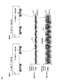
- FIG. 2 is a diagram showing a time history waveform of vehicle body left-right vibration acceleration when abnormal vibration occurs in vehicle B in the abnormality detection device for a railway vehicle of the first embodiment.
- FIG. 3 is a flowchart illustrating a processing procedure in the data analysis unit 100 in the abnormality detection device for the railway vehicle of the first embodiment.
- FIG. 4 is a flowchart illustrating a processing procedure in the comparison processing unit 200 in the abnormality detection device for a railway vehicle according to the first embodiment.
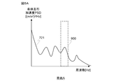
- FIG. 5A is a diagram showing the relationship between the measured value of the vehicle body lateral acceleration PSD of the vehicle A in the normal state and the frequency.
- FIG. 5B is a diagram showing the relationship between the measured value of the vehicle body lateral acceleration PSD of the vehicle B in an abnormal state and the frequency.
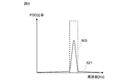
- FIG. 6 is a diagram showing the PSD ratio between the vehicle body left-right acceleration PSD of the vehicle A in the normal state and the vehicle body left-right acceleration PSD of the vehicle B in the abnormal state in the comparison processing unit of the first embodiment.
- FIG. 7 is a flowchart illustrating a processing procedure in the parameter estimation unit 400 in the abnormality detection device for the railway vehicle of the first embodiment.
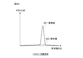
- FIG. 8A is a characteristic diagram showing both the measured value (solid line) and the analyzed value (dotted line) before the estimation of the parameter estimation unit of the first embodiment.
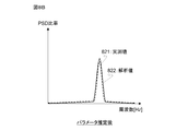
- FIG. 8B is a characteristic diagram showing both the measured value (solid line) and the analyzed value (dotted line) after the estimation of the parameter estimation unit of the first embodiment.
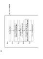
- FIG. 9 is a flowchart illustrating a processing procedure in the abnormality factor estimation unit 400 in the abnormality detection device for the railway vehicle of the first embodiment.
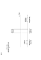
- FIG. 10 is a diagram showing the estimation result of the abnormal factor in the abnormal factor estimation unit of the first embodiment.
- FIG. 11 is a diagram showing a processing flow in the parameter estimation unit in the abnormality detection device for the railway vehicle of the second embodiment.
- FIG. 12 is a diagram showing a processing flow in the parameter estimation unit in the abnormality detection device for the railway vehicle of the third embodiment.
- Rail vehicles are vehicles that are operated along the track to be laid, and include railway vehicles, monorail vehicles, trams, new transportation vehicles, and the like.
- An embodiment of the present invention will be described by taking up a railroad vehicle as a typical example of a rail vehicle.
- FIG. 1 is a functional block diagram showing a system configuration of an abnormality detection device for a railway vehicle.
- the railroad vehicles A and B traveling on the track 20 include a vehicle body 1 and a bogie 16, respectively.
- the vehicle body 1 is mounted on the bogie 16 via an air spring 8.
- the bogie 16 is composed of a bogie frame 11, an air spring 8, a yaw damper 4, an axle box body 12, an axle 13, an axle spring device 14, an axle box support rubber 15 for an axle box serving as a bearing housing for the axle 13, and the like. ..
- the wheel set 13 is rotatably held with respect to the axle box body 12, and the axle box body 12 and the bogie frame 11 are elastically supported in the vertical direction by the axle spring device 14 and also by the axle box support rubber 15. It is elastically supported in the horizontal direction.
- An air spring 8 is arranged between the vehicle body 1 and the bogie frame 11, and the vehicle body 1 is elastically supported by the bogie frame 11 by the air spring 8.
- a vibration data detection unit (vibration data acquisition unit) 60 for acquiring data related to the vibration of the vehicle body 1 is installed on the floor surface of the vehicle body 1.
- the physical quantity detected by the vibration data detection unit 60 in order to acquire data related to vibration is not limited to acceleration, but may be speed, displacement, strain, sound, or the like. However, in the present embodiment, the vibration data detection unit 60 will be described as detecting the acceleration.
- the vibration data detection unit 60 is installed in the vehicle body 1 having a relatively large installation space, it can be installed not only in the vehicle body 1 but also in the bogie frame 11, the axle box body 12, and the like. It is also possible to detect vibration. In the present embodiment, the vibration data detection unit 60 will be described as being installed on the vehicle body 1.
- vibration data detection units 60 may be installed for one vehicle, in the present embodiment, it is assumed that a single vibration data detection unit 60 is installed. Further, the installation position of the vibration data detection unit 60 may be the central position of the vehicle body 1, the position directly above the bogie 16, or the end portion of the vehicle body 1 such as the vehicle equipment room position.
- the vibration acquisition direction of the vibration data detection unit 60 is a translation (forward / backward translation / left / right translation / vertical translation) direction and a rotation (roll / pitch / yaw) direction with respect to the front-back, left-right, and vertical directions with respect to the traveling direction of the railway vehicle. It is applicable to any of the above. In the present embodiment, the vibration data detection unit 60 will be described as detecting vibration in the left-right translation direction.
- the vehicle body 1 includes, for example, an operation data detection unit (operation data acquisition unit) 50 having a function of acquiring operation data such as a travel speed, a travel position, and a occupancy rate from an operation management system that manages operation data.
- an operation data detection unit (operation data acquisition unit) 50 having a function of acquiring operation data such as a travel speed, a travel position, and a occupancy rate from an operation management system that manages operation data.
- FIG. 1 shows an example in which the vibration data detection unit 60 and the operation data detection unit 50 are provided only on two rail vehicles (hereinafter, simply referred to as vehicles), they are provided on three or more plurality of vehicles. You may. Further, the vibration data detection unit 60 and the operation data detection unit 50 may be provided for a plurality of vehicles in one train formation, or may be provided for each vehicle of different train formations traveling on the same track.
- the abnormality factor detection device 30 includes a data analysis unit 100, a comparison processing unit 200, a parameter estimation unit 300, an abnormality factor determination unit 400, and a determination result output unit 500, and detects anomalies that detect the cause of abnormal vibration of a railway vehicle. Configure the device.
- the parameter estimation unit 300 and the abnormality factor determination unit 400 constitute a diagnosis unit.
- the abnormality factor detection device 30 is preferably installed on the ground side such as a depot for inspecting and servicing the vehicle, but may be installed on the upper side of the vehicle.
- the data analysis unit 100, the comparison processing unit 200, the parameter estimation unit 300, the abnormality factor determination unit 400, and the determination result output unit 500 execute, for example, each process described later according to a program stored inside the abnormality factor detection device 30. It is composed of arithmetic units.
- the data analysis unit 100 acquires vibration data detected by the vibration data detection unit 60 and operation data detected by the operation data detection unit 50 from a plurality of vehicles, analyzes the acquired data, and determines whether the vehicle is in a normal state or abnormal. It has a function to identify the state and output vibration data and operation data of those vehicles. The specific processing flow executed by the data analysis unit 100 will be described later.
- the comparison processing unit 200 acquires vibration data and operation data of the vehicle in the abnormal state and the normal state output by the data analysis unit 100, and compares the vehicle in the abnormal state with the vehicle in the normal state based on the acquired data. It has a function to output the result.
- the specific processing flow executed by the comparison processing unit 200 will be described later.
- the parameter estimation unit 300 has a function of estimating parameters related to the internal state of the vehicle from the comparison result between the vehicle in the abnormal state and the vehicle in the normal state output by the comparison processing unit 200.
- the parameters related to the internal state of the vehicle are parameters that can cause abnormal vibration of the railway vehicle.
- the rigidity of the axle box support rubber 15 of the axle box support device installed in the railway vehicle the yaw damper 4 Refers to the damping coefficient of, the wheel tread gradient of the wheelset 13, and the like.
- the specific processing flow executed by the parameter estimation unit 300 will be described later.
- the abnormality factor determination unit 400 has a function of determining an abnormality factor from the estimated value of the parameter output by the parameter estimation unit 300. The specific processing flow executed by the abnormality factor determination unit 400 will be described later.
- the determination result output unit 500 has a function of notifying the driver of the vehicle body 1 and the operation manager and maintenance personnel on the ground of the abnormality factor output by the abnormality factor determination unit 400 via a monitor, a speaker, or the like.
- the processing flow for detecting an abnormality will be described by taking as an example a case where abnormal vibration occurs in the vehicle B due to a decrease in the damping coefficient due to oil leakage of the yaw damper 4 (see the vibration waveform b in FIG. 2).
- a case where an acceleration sensor in the left-right translation direction (hereinafter referred to as a left-right acceleration sensor) installed directly above the trolley position is used for the vibration data detection unit 60 will be described.
- the vibration waveform a in FIG. 2 is a chart showing the vehicle body lateral acceleration 621 measured by the left-right acceleration sensor installed in the vehicle A corresponding to the position of the track, and the vibration waveform b in FIG. 2 corresponds to the position of the track. Then, it is a chart which shows the vehicle body lateral acceleration 622 measured by the lateral acceleration sensor installed in the vehicle B. In the vibration waveforms a and b, it is shown that the higher the measured acceleration, the larger the amplitude of the waveform.
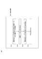
- FIG. 3 is a flowchart illustrating a processing procedure of the data analysis unit 100 in the abnormality detection device for the railway vehicle of FIG. The operation based on the flowchart of FIG. 3 is as follows.
- step S111 the data analysis unit 100 acquires the vehicle body left-right acceleration from the left-right acceleration sensors of a plurality of vehicles, and at the same time, acquires the operation data such as the traveling position, the traveling speed, and the occupancy rate from the operation data detection unit 50. To do.
- step S112 the data analysis unit 100 filters the vehicle body lateral acceleration acquired in step S111 using a well-known filtering technique.
- step S113 As filtering, before the analysis process performed in step S113, such as the process of extracting only the frequency band that is easily perceived by humans from the left-right acceleration of the vehicle body and the process of calculating the RMS (Root Mean Square) value and the maximum value of the acceleration. Processing etc. are performed.
- RMS Root Mean Square
- the data analysis unit 100 sets a traveling section having a particularly large vibration as a representative section from the filtered acceleration, and in this representative section, the vehicle body lateral acceleration data of each vehicle such as vehicle A and vehicle B. And, it performs processing to extract operation data such as running speed and occupancy rate.
- vibration data in the same section can be extracted for vehicle A and vehicle B.
- the representative section is not limited to the traveling section with large vibration, and can be arbitrarily determined. Further, the representative section may be one, or may be two or more sections.
- the section where there is data that the measurement conditions are relatively close such as the traveling speed of each vehicle such as vehicle A and vehicle B being the same or close, the occupancy rate being close, and the measurement date and time being close. You can set it.
- step S114 the data analysis unit 100 compares the vehicle body left-right acceleration data of each vehicle in the representative section, and performs a process of identifying whether each vehicle is in a normal state or an abnormal state.
- a threshold value may be set in advance for the vehicle body acceleration and a threshold value process may be used to determine whether or not the threshold value is exceeded, or the Mahalanobis-Taguchi System (Mahalanobis-Taguchi System).
- Mahalanobis-Taguchi System Mohalanobis-Taguchi System
- the vehicle B in which a large vibration exceeding the threshold value 922 shown in FIG. 2 is generated by the threshold value processing or the like is determined to be in an "abnormal state", and the vehicle A not exceeding the threshold value 922 is ". It shall be judged as "normal state”.
- step S115 the data analysis unit 100 compares the vehicle body lateral acceleration and operation data in the representative section extracted in step S113 with the identification information that each vehicle is in an “abnormal state” or “normal state”. Output to 200.
- FIG. 4 is a flowchart illustrating a processing procedure of the comparison processing unit 200 in the abnormality detection device for the railway vehicle of FIG. The operation based on the flowchart of FIG. 4 is as follows.
- step S211 the comparison processing unit 200 outputs identification information such as that the vehicle A is in a normal state and the vehicle B is in an abnormal state, and the vehicle body lateral acceleration and operation data in the representative section, which are output from the data analysis unit 100. To get.
- step S212 the comparison processing unit 200 calculates the vehicle body lateral acceleration PSD (Power Spectrum Density) with respect to the vehicle body lateral acceleration of each vehicle from the acquired vehicle body lateral acceleration.
- PSD is a spectral function expressed as a power value per unit frequency width (1 Hz width).
- the vehicle A is calculated as the vehicle body lateral acceleration PSD721 of the vehicle in the normal state as shown in FIG. 5A
- the vehicle B is calculated as the vehicle body lateral acceleration PSD722 of the vehicle in the abnormal state as shown in FIG. 5B.
- the vehicle body left-right acceleration PSD722 of the vehicle B is larger than the vehicle body left-right acceleration PSD721 of the vehicle A in the predetermined frequency band 900.
- step S213 the comparison processing unit 200 calculates the PSD ratio 821, which is the ratio of the vehicle body left-right acceleration PSD721 of the vehicle A in the normal state to the vehicle body left-right acceleration PSD722 of the vehicle B in the abnormal state.
- This PSD ratio 821 represents a frequency band in which PSD differs from the normal state in the abnormal state and the degree thereof.
- the PSD ratio 821 is significantly increased in the frequency band 900.
- the data analysis unit 100 extracts the vibration data of the same section in advance, the influence of the difference in response due to the difference in the section of the track is reduced, and then the transmission characteristics change in the normal state and the abnormal state of the vehicle.
- the change in response due to can be extracted as the PSD ratio 821.
- any value that represents the feature amount related to the change between the abnormal state and the normal state can be used instead of the PSD ratio.
- the ratio of the RMS value of the vehicle body lateral acceleration between the abnormal state and the normal state, etc. Can also be used.
- step S214 the comparison processing unit 200 outputs this PSD ratio 821 to the parameter estimation unit 300.
- the parameters estimated as abnormal factors are the spring constant of the axle box support rubber 15, the damping coefficient of the yaw damper 4, and the wheel tread gradient of the wheelset 13 will be described.
- step S311 the parameter estimation unit 300 acquires the PSD ratio 821 output by the comparison processing unit 200. This is called the measured PSD ratio 821.
- the parameter estimation unit 300 calculates the analysis value of the vehicle body left-right acceleration PSD when the parameters related to the internal state of the vehicle are in the normal state using the mechanical model.
- This mechanical model is a model for predicting the vibration characteristics of railway vehicles.
- the vehicle body 1, the bogie 16, and the wheel shaft are placed on a virtual track that simulates track irregularities such as track deviation (degree of unevenness in the length direction of the rail side surface) and rail deviation (error with respect to the basic dimensions of the left and right rail spacing).
- Vehicle left-right system dynamics that predicts vehicle body left-right vibration when a virtual vehicle with each rigid body connected by springs and dampers runs by imitating 13 with a rigid body and the axle box support rubber 15 and yaw damper 4 with springs and dampers.
- Various dynamic models can be used according to the type of vibration to be predicted, such as a model and a vehicle vertical system dynamic model that predicts vehicle vertical vibration.
- the orbital irregularity data may be used. However, if there is no actual measurement data of track irregularity, prepare typical track irregularity data according to the track condition (track condition: "good”, “normal”, “bad”, etc.) in advance, and run a commercial vehicle. A method of defining a virtual orbit by selecting and using it according to a route or the like may be adopted.
- parameters such as the spring constant of the axle box support rubber 15, the damping coefficient of the yaw damper 4, and the wheel tread gradient of the wheel axle 13 are set to normal values, and the analysis value of the vehicle body lateral acceleration PSD is set using a mechanical model. Is calculated.
- the normal values are the spring constant of the axle box support rubber 15, the damping coefficient of the yaw damper 4 is the design value and the element test value, and the wheel tread gradient of the wheelset 13 is the value in the new state and management during maintenance. Values etc. are used.
- step S313 and subsequent steps the parameter estimation unit 300 estimates the parameters of the vehicle in the abnormal state.
- the parameter estimation unit 300 sets the initial estimation value of the parameter.
- the initial estimated value of the parameter may be a normal value of the parameter or a randomly generated value.
- the parameter estimation unit 300 sets initial estimation values such as the spring constant of the axle box support rubber 15, the damping coefficient of the yaw damper 4, and the wheel tread gradient of the wheelset 13.
- step S314 the parameter estimation unit 300 estimates the parameters in the abnormal state using the actually measured PSD ratio 821 processed by the comparison processing unit 200.
- the parameter estimation unit 300 calculates the analysis value of the vehicle body left-right acceleration PSD in the initial estimated value of the parameter by the mechanical model.
- step S314 the parameter estimation unit 300 compares the analysis value of the vehicle body left / right acceleration PSD in the initial estimation value of this parameter with the analysis value of the vehicle body left / right acceleration PSD in the parameter in the normal state calculated in step S312.
- the analysis PSD ratio 822 is calculated.
- the parameter estimation unit 300 determines the parameter estimation value so that the analysis PSD ratio 822 matches the actually measured PSD ratio 821, that is, the error is minimized. ..
- any one that can evaluate the error can be used without restriction, but in the present embodiment, as shown in FIGS. 8A and 8B, the measured PSD ratio 821 for each frequency of the PSD ratio and the analyzed PSD ratio 822.
- the value obtained by integrating the differences hereinafter referred to as the integrated difference value).
- the calculated PSD ratio is analyzed as the measured PSD ratio 821 with respect to the spring constant of the axle box support rubber 15, the damping coefficient of the yaw damper 4, the wheel tread gradient of the wheelset 13, and the like. Obtain an estimate of the parameters such that the PSD ratio 822 matches.
- FIG. 8A shows the frequency on the horizontal axis, the PSD ratio on the vertical axis, the measured PSD ratio 821 shown by the solid line before parameter estimation, and the characteristic diagram showing the analyzed PSD ratio 822 shown by the dotted line.
- FIG. 8B shows the frequency on the horizontal axis.
- the vertical axis shows the PSD ratio, and it is a characteristic diagram showing the measured PSD ratio 821 after parameter estimation and the analyzed PSD ratio 822 shown by the dotted line.
- step S315 the parameter estimation unit 300 outputs the estimated value of this parameter to the abnormality factor determination unit 400.
- one left-right acceleration sensor is installed in the vehicle body 1.
- the left-right acceleration sensors are installed on the vehicle body 1, the bogie 16, the axle box body 12, etc.
- the parameters are set so that the measured values of the plurality of left-right accelerations detected from them and the analysis values match. By updating, the parameter estimation can be made more accurate.
- the abnormality factor determination unit 400 acquires the estimated value of the parameter output by the parameter estimation unit 300.
- the abnormality factor determination unit 400 acquires the spring constant of the axle box support rubber 15, the damping coefficient of the yaw damper 4, and the estimated value of the wheel tread gradient of the wheelset 13.
- step S412 the abnormality factor determination unit 400 calculates the ratio between the estimated value and the normal value of each parameter.
- step S413 the abnormality factor determination unit 400 compares this ratio with the preset threshold value for each parameter, and determines between the normal state and the abnormal state.
- the abnormality factor determination unit 400 can be said to be close to the normal state, and therefore determines the normal state (step S414). On the other hand, if the ratio is a parameter exceeding the threshold value, the abnormality factor determination unit 400 determines that it is in an abnormal state (step S415).
- the abnormality factor determination unit 400 outputs to the determination result output unit 500 in step S416 with the parameter determined to be the abnormal state as the abnormality factor.
- FIG. 10 schematically shows an example of determining normality and abnormality of the parameters in step S413, with respect to abnormal factor elements such as the spring rigidity of the axle box support rubber 15, the damping coefficient of the yaw damper 4, and the wheel tread gradient. It is a schematic diagram which showed the ratio of the estimated value of a parameter, a normal value, and a threshold value.
- the attenuation coefficient of the yaw damper 4 in which the ratio of the estimated value and the normal value of the parameter exceeds the threshold value 91 is determined to be an abnormal state. Then, the determination result that the decrease in the damping coefficient of the yaw damper 4 is the abnormality factor is output from the abnormality factor determination unit 400 to the determination result output unit 500.
- the determination result output unit 500 notifies the driver on the vehicle, the operation manager on the ground, the maintenance staff, etc. of the estimation result of this abnormal factor by using a well-known communication technology.
- an abnormality factor such as a decrease in the damping coefficient of the yaw damper 4.
- the vehicle abnormality detection device has the same configuration as that of the first embodiment, but the parameter estimation unit 300 executes a process as described below using the flowchart of FIG. In addition, only the points different from Example 1 will be described below.
- step S312a is added as a process when the orbital irregularity data used in the analysis by the mechanical model is not used as the orbital irregularity data prepared in advance such as the measured data. It was done.
- step S311 the parameter estimation unit 300 acquires the measured PSD ratio 821 processed by the comparison processing unit 200.
- step S312a the parameter estimation unit 300 performs a process of identifying the track irregularity based on the measured value of the vehicle body lateral acceleration PSD of the vehicle in the normal state.
- the parameter estimation unit 300 performs a process of identifying track irregularity data so that the analysis value of the vehicle body left-right acceleration PSD calculated using the dynamic model and the measured value of the vehicle body left-right acceleration PSD match. ..
- the track irregularity data is identified by using the dynamic model from the vehicle body lateral acceleration PSD of the vehicle A in the normal state.
- the parameter estimation unit 300 performs the same process as in the first embodiment using the orbital irregularity data identified in step S312a.
- vehicle body left-right acceleration PSD Although an example using the vehicle body left-right acceleration PSD has been described in this embodiment, it is not limited to the vehicle body left-right acceleration PSD as long as the track irregularity data can be identified.
- the railroad vehicle abnormality detection device of the present embodiment can determine the cause of the vehicle abnormality without preparing track irregularity data in advance.
- the vehicle abnormality detection device has the same configuration as that of the first embodiment, but the parameter estimation unit 300 executes a process as described below using the flowchart of FIG. In addition, only the difference from the said Example will be described below.
- the abnormality detection device of the present embodiment is obtained by adding steps S314a and S315a to the abnormality detection device of the above embodiment as processing when the parameter estimation accuracy is low in the parameter estimation unit 300.
- the parameter estimation unit 300 estimates the parameters so that the integrated difference value between the measured PSD ratio 821 and the analysis PSD ratio 822 of the PSD ratio is minimized.
- the integrated difference value serves as an index indicating the estimation accuracy.
- step S314a when the integrated difference value is equal to or less than a preset threshold value, the parameter estimation unit 300 determines that the estimation accuracy is equal to or higher than the reference level, and determines that the parameter is in step S315 as in the first embodiment.
- the estimated value of is output to the abnormality factor determination unit 400.
- the parameter estimation unit 300 determines that the estimation accuracy is lower than the reference level, and outputs only the information regarding the abnormality of the vehicle in step S315a. , Does not output the estimated value of the parameter (parameter estimated to be an abnormal factor).
- the railcar abnormality detection device of the present embodiment can output at least that there is an abnormality in the vehicle without interrupting the abnormality detection even when the parameter estimation accuracy is not sufficient.
Landscapes
- Engineering & Computer Science (AREA)
- Health & Medical Sciences (AREA)
- Biomedical Technology (AREA)
- General Health & Medical Sciences (AREA)
- Mechanical Engineering (AREA)
- Physics & Mathematics (AREA)
- General Physics & Mathematics (AREA)
- Electric Propulsion And Braking For Vehicles (AREA)
Abstract
Description
上記した以外の課題、構成及び効果は、以下の実施形態の説明により明らかにされる。
はじめに、鉄道車両の異常検出装置の構成について図1を参照して説明する。
図1は、鉄道車両の異常検出装置のシステム構成を示す機能ブロック図である。
なお、振動に関するデータを取得するために振動データ検出部60が検出する物理量としては、加速度に限るものではなく、速度、変位、ひずみ、音などでも良い。ただし、本実施形態では振動データ検出部60が加速度を検出するものとして説明する。
また、振動データ検出部60と運行データ検出部50は、1列車編成中の複数の車両に備えても良いし、同じ軌道上を走行する異なる列車編成それぞれの車両に備えることもできる。
なお、本実施形態では振動データ検出部60に、台車位置の直上に設置した左右並進方向の加速度センサ(以下、左右加速度センサ)を用いた場合で説明する。
本実施形態では、異常要因判定部400は、軸箱支持ゴム15のばね定数や、ヨーダンパ4の減衰係数、輪軸13の車輪踏面勾配の推定値を取得する。
本実施形態に係る車両の異常検出装置は、前記実施形態1と同様の構成を有するが、そのパラメータ推定部300は、図11のフローチャートを用いて次に説明するような処理を実行する。なお、実施例1と異なる点のみを主として、以下に説明する。
本実施形態に係る車両の異常検出装置は、前記実施形態1と同様の構成を有するが、そのパラメータ推定部300は図12のフローチャートを用いて次に説明するような処理を実行する。なお、前記実施例と異なる点のみを主として、以下に説明する。
Claims (12)
- 軌条車両の振動データを取得する振動データ取得部と、
軌条車両の運行データを取得する運行データ取得部と、
前記振動データと前記運行データに基づいて、同じ軌道を走行する軌条車両が正常状態か異常状態かを識別し、正常状態又は異常状態に対応付けて軌条車両の振動データを抽出するデータ分析部と、
正常状態の軌条車両の前記振動データと、異常状態の軌条車両の前記振動データとを比較して、比較結果を算出する比較処理部と、
前記比較結果に基づき、異常状態と識別された軌条車両における振動の異常要因を判定する診断部と、を有する、
ことを特徴とする軌条車両の異常検出装置。 - 請求項1に記載の軌条車両の異常検出装置であって、
前記診断部は、
前記比較処理部で算出した前記比較結果に基づいて、軌条車両の内部状態に関するパラメータを推定するパラメータ推定部と、
推定された前記パラメータに基づいて、前記軌条車両における振動の異常要因を判定する異常要因判定部と、を備えた、
ことを特徴とする軌条車両の異常検出装置。 - 請求項2に記載の軌条車両の異常検出装置であって、
前記パラメータ推定部は、正常状態の軌条車両と異常状態の軌条車両のPSD比率に基づいて、軌条車両の内部状態に関する前記パラメータを推定する、
ことを特徴とする軌条車両の異常検出装置。 - 請求項2または3に記載の軌条車両の異常検出装置であって、
前記パラメータ推定部は、軌条車両の振動特性を予測するための力学モデルに基づいて、軌条車両の内部状態に関する前記パラメータを推定する、
ことを特徴とする軌条車両の異常検出装置。 - 請求項4に記載の軌条車両の異常検出装置であって、
前記力学モデルが、軌条車両左右系力学モデルあるいは軌条車両上下系力学モデルである、
ことを特徴とする軌条車両の異常検出装置。 - 請求項2~5のいずれか一項に記載の軌条車両の異常検出装置であって、
前記異常要因判定部は、前記パラメータ推定部で推定された軌条車両の内部状態に関する前記パラメータの推定値と、正常値との比較結果に基づいて、前記軌条車両における振動の異常要因を判定する、
ことを特徴とする軌条車両の異常検出装置。 - 請求項2~6のいずれか一項に記載の軌条車両の異常検出装置であって、
前記パラメータ推定部は、前記軌条車両の振動データに基づいて、軌道不整を同定する、
ことを特徴とする軌条車両の異常検出装置。 - 請求項2~7のいずれか一項に記載の軌条車両の異常検出装置であって、
前記パラメータ推定部は、軌条車両の内部状態に関する前記パラメータの推定値の推定精度を求め、求めた前記推定精度が基準レベル以上である場合は、異常要因と推定されるパラメータを出力し、求めた前記推定精度が基準レベルより低い場合は、軌条車両が異常であることを示す情報のみを出力する、
ことを特徴とする軌条車両の異常検出装置。 - 請求項1~8のいずれか一項に記載の軌条車両の異常検出装置であって、
前記振動データ取得部が、前記軌条車両の車体、台車枠、あるいは軸箱体の振動を検出する、
ことを特徴とする軌条車両の異常検出装置。 - 請求項1~9のいずれか一項に記載の軌条車両の異常検出装置であって、
前記振動データ取得部及び前記運行データ取得部は、単独の列車編成中の複数の軌条車両、または同じ軌道上を走行する異なる列車編成それぞれの軌条車両に設けられている、
ことを特徴とする軌条車両の異常検出装置。 - 請求項1~10のいずれか一項に記載の軌条車両の異常検出装置であって、
前記データ分析部は、軌条車両の走行区間の中から設定された代表区間にて、各軌条車両の振動データを抽出する、
ことを特徴とする軌条車両の異常検出装置。 - 請求項1~11のいずれか一項に記載の軌条車両の異常検出装置であって、
前記比較処理部は、各軌条車両の振動データが閾値を超える場合は、その軌条車両を異常状態にあると判別し、前記振動データが前記閾値を超えない場合は、その軌条車両は正常状態にあると判別する、
ことを特徴とする軌条車両の異常検出装置。
Priority Applications (4)
| Application Number | Priority Date | Filing Date | Title |
|---|---|---|---|
| EP19915577.1A EP4012370B1 (en) | 2019-08-07 | 2019-08-07 | Railway vehicle anomaly detection device |
| JP2020535259A JP6935595B2 (ja) | 2019-08-07 | 2019-08-07 | 軌条車両の異常検出装置 |
| EP25180229.4A EP4592664A1 (en) | 2019-08-07 | 2019-08-07 | Abnormality detection apparatus for rail vehicles |
| PCT/JP2019/031152 WO2021024423A1 (ja) | 2019-08-07 | 2019-08-07 | 軌条車両の異常検出装置 |
Applications Claiming Priority (1)
| Application Number | Priority Date | Filing Date | Title |
|---|---|---|---|
| PCT/JP2019/031152 WO2021024423A1 (ja) | 2019-08-07 | 2019-08-07 | 軌条車両の異常検出装置 |
Publications (1)
| Publication Number | Publication Date |
|---|---|
| WO2021024423A1 true WO2021024423A1 (ja) | 2021-02-11 |
Family
ID=74503992
Family Applications (1)
| Application Number | Title | Priority Date | Filing Date |
|---|---|---|---|
| PCT/JP2019/031152 Ceased WO2021024423A1 (ja) | 2019-08-07 | 2019-08-07 | 軌条車両の異常検出装置 |
Country Status (3)
| Country | Link |
|---|---|
| EP (2) | EP4592664A1 (ja) |
| JP (1) | JP6935595B2 (ja) |
| WO (1) | WO2021024423A1 (ja) |
Cited By (6)
| Publication number | Priority date | Publication date | Assignee | Title |
|---|---|---|---|---|
| JP2023000741A (ja) * | 2021-06-18 | 2023-01-04 | 株式会社日立製作所 | 乗り心地向上支援装置 |
| WO2023199369A1 (ja) * | 2022-04-11 | 2023-10-19 | 株式会社日立製作所 | 寿命評価装置および方法 |
| JP2023172234A (ja) * | 2022-05-23 | 2023-12-06 | 株式会社日立製作所 | 鉄道車両の状態監視システム |
| JP2024064145A (ja) * | 2022-10-27 | 2024-05-14 | 日立Astemo株式会社 | 車両用制振装置および鉄道車両 |
| CN119198145A (zh) * | 2024-11-27 | 2024-12-27 | 常州中量高新技术有限公司 | 一种用于列车制动状态下的智能测试系统 |
| US20250108842A1 (en) * | 2023-09-29 | 2025-04-03 | Robert Bosch Gmbh | Prediction and identification of potential railway system anomalies |
Families Citing this family (1)
| Publication number | Priority date | Publication date | Assignee | Title |
|---|---|---|---|---|
| CN121019646B (zh) * | 2025-10-24 | 2025-12-30 | 中数智科(杭州)科技有限公司 | 一种铁路轨道磨耗线检测系统及方法 |
Citations (8)
| Publication number | Priority date | Publication date | Assignee | Title |
|---|---|---|---|---|
| JPS6196440A (ja) * | 1984-10-13 | 1986-05-15 | フリード・クルツプ・ゲゼルシヤフト・ミツト・ベシユレンクテル・ハフツング | 車両の要修理構成部材を特定する方法 |
| JPH1020930A (ja) * | 1996-07-04 | 1998-01-23 | Hitachi Ltd | 予防保全方法 |
| JP2004170080A (ja) | 2002-11-15 | 2004-06-17 | Kawasaki Heavy Ind Ltd | 車両の異常検出方法及び装置、並びに車両 |
| JP2011245917A (ja) * | 2010-05-24 | 2011-12-08 | Hitachi Ltd | 鉄道車両の状態監視装置及び状態監視方法、並びに鉄道車両 |
| CN103592122A (zh) * | 2013-10-25 | 2014-02-19 | 北京交通大学 | 城市轨道交通列车走行部故障诊断设备及方法 |
| US20150051792A1 (en) * | 2011-12-07 | 2015-02-19 | Railway Metrics And Dynamics Sweden Ab | Method and system for detection and analysis of railway bogie operational problems |
| WO2018155348A1 (ja) * | 2017-02-23 | 2018-08-30 | 三菱重工エンジニアリング株式会社 | 異常監視装置、異常監視方法およびプログラム |
| JP2018179986A (ja) * | 2017-04-11 | 2018-11-15 | 公益財団法人鉄道総合技術研究所 | 異常診断装置およびプログラム |
Family Cites Families (1)
| Publication number | Priority date | Publication date | Assignee | Title |
|---|---|---|---|---|
| WO2017064734A1 (en) * | 2015-10-16 | 2017-04-20 | Politecnico Di Bari | Method for determining the modal parameters of road or rail vehicles and for the indirect characterization of road or rail profiles |
-
2019
- 2019-08-07 WO PCT/JP2019/031152 patent/WO2021024423A1/ja not_active Ceased
- 2019-08-07 EP EP25180229.4A patent/EP4592664A1/en active Pending
- 2019-08-07 EP EP19915577.1A patent/EP4012370B1/en active Active
- 2019-08-07 JP JP2020535259A patent/JP6935595B2/ja active Active
Patent Citations (8)
| Publication number | Priority date | Publication date | Assignee | Title |
|---|---|---|---|---|
| JPS6196440A (ja) * | 1984-10-13 | 1986-05-15 | フリード・クルツプ・ゲゼルシヤフト・ミツト・ベシユレンクテル・ハフツング | 車両の要修理構成部材を特定する方法 |
| JPH1020930A (ja) * | 1996-07-04 | 1998-01-23 | Hitachi Ltd | 予防保全方法 |
| JP2004170080A (ja) | 2002-11-15 | 2004-06-17 | Kawasaki Heavy Ind Ltd | 車両の異常検出方法及び装置、並びに車両 |
| JP2011245917A (ja) * | 2010-05-24 | 2011-12-08 | Hitachi Ltd | 鉄道車両の状態監視装置及び状態監視方法、並びに鉄道車両 |
| US20150051792A1 (en) * | 2011-12-07 | 2015-02-19 | Railway Metrics And Dynamics Sweden Ab | Method and system for detection and analysis of railway bogie operational problems |
| CN103592122A (zh) * | 2013-10-25 | 2014-02-19 | 北京交通大学 | 城市轨道交通列车走行部故障诊断设备及方法 |
| WO2018155348A1 (ja) * | 2017-02-23 | 2018-08-30 | 三菱重工エンジニアリング株式会社 | 異常監視装置、異常監視方法およびプログラム |
| JP2018179986A (ja) * | 2017-04-11 | 2018-11-15 | 公益財団法人鉄道総合技術研究所 | 異常診断装置およびプログラム |
Non-Patent Citations (1)
| Title |
|---|
| See also references of EP4012370A4 |
Cited By (8)
| Publication number | Priority date | Publication date | Assignee | Title |
|---|---|---|---|---|
| JP2023000741A (ja) * | 2021-06-18 | 2023-01-04 | 株式会社日立製作所 | 乗り心地向上支援装置 |
| JP7570979B2 (ja) | 2021-06-18 | 2024-10-22 | 株式会社日立製作所 | 乗り心地向上支援装置 |
| WO2023199369A1 (ja) * | 2022-04-11 | 2023-10-19 | 株式会社日立製作所 | 寿命評価装置および方法 |
| JP2023172234A (ja) * | 2022-05-23 | 2023-12-06 | 株式会社日立製作所 | 鉄道車両の状態監視システム |
| JP2024064145A (ja) * | 2022-10-27 | 2024-05-14 | 日立Astemo株式会社 | 車両用制振装置および鉄道車両 |
| JP7843211B2 (ja) | 2022-10-27 | 2026-04-09 | Astemo株式会社 | 車両用制振装置および鉄道車両 |
| US20250108842A1 (en) * | 2023-09-29 | 2025-04-03 | Robert Bosch Gmbh | Prediction and identification of potential railway system anomalies |
| CN119198145A (zh) * | 2024-11-27 | 2024-12-27 | 常州中量高新技术有限公司 | 一种用于列车制动状态下的智能测试系统 |
Also Published As
| Publication number | Publication date |
|---|---|
| EP4012370A1 (en) | 2022-06-15 |
| EP4012370B1 (en) | 2025-06-04 |
| JP6935595B2 (ja) | 2021-09-15 |
| JPWO2021024423A1 (ja) | 2021-09-13 |
| EP4592664A1 (en) | 2025-07-30 |
| EP4012370A4 (en) | 2023-05-17 |
Similar Documents
| Publication | Publication Date | Title |
|---|---|---|
| JP6935595B2 (ja) | 軌条車両の異常検出装置 | |
| JP4298433B2 (ja) | 鉄道車両の異常検知装置 | |
| JP6838176B2 (ja) | 鉄道車両の異常検出装置および方法 | |
| JP5525404B2 (ja) | 鉄道車両の状態監視装置及び状態監視方法、並びに鉄道車両 | |
| JP5595266B2 (ja) | 軌道車両の台車コンポーネントのエラー監視装置 | |
| JP5583006B2 (ja) | 軌道車両の台車コンポーネントのエラー監視装置 | |
| JP5382991B2 (ja) | 軌道系交通システムの異常診断方法及び異常診断システム | |
| KR20120095977A (ko) | 적어도 하나의 휠 세트를 포함하는 철도 차량의 보기의 상태를 모니터링하는 방법 | |
| JP7776973B2 (ja) | 状態監視装置及び状態監視方法 | |
| CN108698622A (zh) | 轨道状态评价方法、装置以及程序 | |
| GB2554014A (en) | Status-monitoring device for railroad vehicle, status monitoring system, and train vehicle | |
| JP6867826B2 (ja) | 異常監視装置、異常監視方法およびプログラム | |
| CN116252820B (zh) | 改进频域积分法驱动的高速列车车轮多边形定量检测方法 | |
| CN111444574A (zh) | 基于动力学分析的传感器布局优化方法 | |
| KR102094105B1 (ko) | 다수 개의 매개변수에 의한 철도 차량의 진단 시스템 및 그에 의한 철도 차량의 안전 진단 방법 | |
| WO2023199369A1 (ja) | 寿命評価装置および方法 | |
| JP6669600B2 (ja) | 鉄道車両の状態監視システム | |
| CN112284775B (zh) | 铁路客车故障评判方法及系统 | |
| JP2025015512A (ja) | 鉄道車両運行安全診断システムおよび診断方法 | |
| JP7788947B2 (ja) | 車両検査システム、車両検査方法、および車両検査プログラム | |
| Elia et al. | Condition monitoring of the railway line and overhead equipment through onboard train measurement-an Italian experience | |
| JP7445406B2 (ja) | 監視装置、監視方法及びプログラム | |
| KR200488973Y1 (ko) | 철도차량의 승차감 분석장치 | |
| JP6498102B2 (ja) | 車両の一次ばね系診断装置 | |
| JP7402127B2 (ja) | 軌道の保守要否判断方法、保守要否判断装置および車両 |
Legal Events
| Date | Code | Title | Description |
|---|---|---|---|
| ENP | Entry into the national phase |
Ref document number: 2020535259 Country of ref document: JP Kind code of ref document: A |
|
| 121 | Ep: the epo has been informed by wipo that ep was designated in this application |
Ref document number: 19915577 Country of ref document: EP Kind code of ref document: A1 |
|
| NENP | Non-entry into the national phase |
Ref country code: DE |
|
| ENP | Entry into the national phase |
Ref document number: 2019915577 Country of ref document: EP Effective date: 20220307 |
|
| WWG | Wipo information: grant in national office |
Ref document number: 2019915577 Country of ref document: EP |