WO2021065477A1 - 印刷装置及び印刷用カセット - Google Patents
印刷装置及び印刷用カセット Download PDFInfo
- Publication number
- WO2021065477A1 WO2021065477A1 PCT/JP2020/034877 JP2020034877W WO2021065477A1 WO 2021065477 A1 WO2021065477 A1 WO 2021065477A1 JP 2020034877 W JP2020034877 W JP 2020034877W WO 2021065477 A1 WO2021065477 A1 WO 2021065477A1
- Authority
- WO
- WIPO (PCT)
- Prior art keywords
- printing
- gear
- cassette
- drive shaft
- spool
- Prior art date
- Legal status (The legal status is an assumption and is not a legal conclusion. Google has not performed a legal analysis and makes no representation as to the accuracy of the status listed.)
- Ceased
Links
Images






Classifications
-
- B—PERFORMING OPERATIONS; TRANSPORTING
- B41—PRINTING; LINING MACHINES; TYPEWRITERS; STAMPS
- B41J—TYPEWRITERS; SELECTIVE PRINTING MECHANISMS, i.e. MECHANISMS PRINTING OTHERWISE THAN FROM A FORME; CORRECTION OF TYPOGRAPHICAL ERRORS
- B41J11/00—Devices or arrangements of selective printing mechanisms, e.g. ink-jet printers or thermal printers, for supporting or handling copy material in sheet or web form
- B41J11/02—Platens
- B41J11/04—Roller platens
-
- B—PERFORMING OPERATIONS; TRANSPORTING
- B41—PRINTING; LINING MACHINES; TYPEWRITERS; STAMPS
- B41J—TYPEWRITERS; SELECTIVE PRINTING MECHANISMS, i.e. MECHANISMS PRINTING OTHERWISE THAN FROM A FORME; CORRECTION OF TYPOGRAPHICAL ERRORS
- B41J15/00—Devices or arrangements of selective printing mechanisms, e.g. ink-jet printers or thermal printers, specially adapted for supporting or handling copy material in continuous form, e.g. webs
- B41J15/04—Supporting, feeding, or guiding devices; Mountings for web rolls or spindles
- B41J15/044—Cassettes or cartridges containing continuous copy material, tape, for setting into printing devices
-
- B—PERFORMING OPERATIONS; TRANSPORTING
- B41—PRINTING; LINING MACHINES; TYPEWRITERS; STAMPS
- B41J—TYPEWRITERS; SELECTIVE PRINTING MECHANISMS, i.e. MECHANISMS PRINTING OTHERWISE THAN FROM A FORME; CORRECTION OF TYPOGRAPHICAL ERRORS
- B41J15/00—Devices or arrangements of selective printing mechanisms, e.g. ink-jet printers or thermal printers, specially adapted for supporting or handling copy material in continuous form, e.g. webs
- B41J15/04—Supporting, feeding, or guiding devices; Mountings for web rolls or spindles
- B41J15/042—Supporting, feeding, or guiding devices; Mountings for web rolls or spindles for loading rolled-up continuous copy material into printers, e.g. for replacing a used-up paper roll; Point-of-sale printers with openable casings allowing access to the rolled-up continuous copy material
-
- B—PERFORMING OPERATIONS; TRANSPORTING
- B41—PRINTING; LINING MACHINES; TYPEWRITERS; STAMPS
- B41J—TYPEWRITERS; SELECTIVE PRINTING MECHANISMS, i.e. MECHANISMS PRINTING OTHERWISE THAN FROM A FORME; CORRECTION OF TYPOGRAPHICAL ERRORS
- B41J15/00—Devices or arrangements of selective printing mechanisms, e.g. ink-jet printers or thermal printers, specially adapted for supporting or handling copy material in continuous form, e.g. webs
- B41J15/04—Supporting, feeding, or guiding devices; Mountings for web rolls or spindles
- B41J15/046—Supporting, feeding, or guiding devices; Mountings for web rolls or spindles for the guidance of continuous copy material, e.g. for preventing skewed conveyance of the continuous copy material
-
- B—PERFORMING OPERATIONS; TRANSPORTING
- B41—PRINTING; LINING MACHINES; TYPEWRITERS; STAMPS
- B41J—TYPEWRITERS; SELECTIVE PRINTING MECHANISMS, i.e. MECHANISMS PRINTING OTHERWISE THAN FROM A FORME; CORRECTION OF TYPOGRAPHICAL ERRORS
- B41J17/00—Mechanisms for manipulating page-width impression-transfer material, e.g. carbon paper
- B41J17/02—Feeding mechanisms
-
- B—PERFORMING OPERATIONS; TRANSPORTING
- B41—PRINTING; LINING MACHINES; TYPEWRITERS; STAMPS
- B41J—TYPEWRITERS; SELECTIVE PRINTING MECHANISMS, i.e. MECHANISMS PRINTING OTHERWISE THAN FROM A FORME; CORRECTION OF TYPOGRAPHICAL ERRORS
- B41J3/00—Typewriters or selective printing or marking mechanisms characterised by the purpose for which they are constructed
- B41J3/407—Typewriters or selective printing or marking mechanisms characterised by the purpose for which they are constructed for marking on special material
- B41J3/4075—Tape printers; Label printers
-
- B—PERFORMING OPERATIONS; TRANSPORTING
- B41—PRINTING; LINING MACHINES; TYPEWRITERS; STAMPS
- B41J—TYPEWRITERS; SELECTIVE PRINTING MECHANISMS, i.e. MECHANISMS PRINTING OTHERWISE THAN FROM A FORME; CORRECTION OF TYPOGRAPHICAL ERRORS
- B41J32/00—Ink-ribbon cartridges
-
- B—PERFORMING OPERATIONS; TRANSPORTING
- B41—PRINTING; LINING MACHINES; TYPEWRITERS; STAMPS
- B41J—TYPEWRITERS; SELECTIVE PRINTING MECHANISMS, i.e. MECHANISMS PRINTING OTHERWISE THAN FROM A FORME; CORRECTION OF TYPOGRAPHICAL ERRORS
- B41J33/00—Apparatus or arrangements for feeding ink ribbons or like character-size impression-transfer material
- B41J33/14—Ribbon-feed devices or mechanisms
- B41J33/16—Ribbon-feed devices or mechanisms with drive applied to spool or spool spindle
- B41J33/22—Ribbon-feed devices or mechanisms with drive applied to spool or spool spindle by gears or pulleys
-
- B—PERFORMING OPERATIONS; TRANSPORTING
- B65—CONVEYING; PACKING; STORING; HANDLING THIN OR FILAMENTARY MATERIAL
- B65H—HANDLING THIN OR FILAMENTARY MATERIAL, e.g. SHEETS, WEBS, CABLES
- B65H18/00—Winding webs
- B65H18/08—Web-winding mechanisms
- B65H18/14—Mechanisms in which power is applied to web roll, e.g. to effect continuous advancement of web
- B65H18/145—Reel-to-reel type web winding and unwinding mechanisms
-
- B—PERFORMING OPERATIONS; TRANSPORTING
- B65—CONVEYING; PACKING; STORING; HANDLING THIN OR FILAMENTARY MATERIAL
- B65H—HANDLING THIN OR FILAMENTARY MATERIAL, e.g. SHEETS, WEBS, CABLES
- B65H23/00—Registering, tensioning, smoothing or guiding webs
- B65H23/02—Registering, tensioning, smoothing or guiding webs transversely
- B65H23/032—Controlling transverse register of web
- B65H23/035—Controlling transverse register of web by guide bars
-
- B—PERFORMING OPERATIONS; TRANSPORTING
- B41—PRINTING; LINING MACHINES; TYPEWRITERS; STAMPS
- B41J—TYPEWRITERS; SELECTIVE PRINTING MECHANISMS, i.e. MECHANISMS PRINTING OTHERWISE THAN FROM A FORME; CORRECTION OF TYPOGRAPHICAL ERRORS
- B41J2/00—Typewriters or selective printing mechanisms characterised by the printing or marking process for which they are designed
- B41J2/315—Typewriters or selective printing mechanisms characterised by the printing or marking process for which they are designed characterised by selective application of heat to a heat sensitive printing or impression-transfer material
- B41J2/32—Typewriters or selective printing mechanisms characterised by the printing or marking process for which they are designed characterised by selective application of heat to a heat sensitive printing or impression-transfer material using thermal heads
- B41J2/325—Typewriters or selective printing mechanisms characterised by the printing or marking process for which they are designed characterised by selective application of heat to a heat sensitive printing or impression-transfer material using thermal heads by selective transfer of ink from ink carrier, e.g. from ink ribbon or sheet
-
- B—PERFORMING OPERATIONS; TRANSPORTING
- B41—PRINTING; LINING MACHINES; TYPEWRITERS; STAMPS
- B41J—TYPEWRITERS; SELECTIVE PRINTING MECHANISMS, i.e. MECHANISMS PRINTING OTHERWISE THAN FROM A FORME; CORRECTION OF TYPOGRAPHICAL ERRORS
- B41J3/00—Typewriters or selective printing or marking mechanisms characterised by the purpose for which they are constructed
- B41J3/36—Typewriters or selective printing or marking mechanisms characterised by the purpose for which they are constructed for portability, i.e. hand-held printers or laptop printers
-
- B—PERFORMING OPERATIONS; TRANSPORTING
- B65—CONVEYING; PACKING; STORING; HANDLING THIN OR FILAMENTARY MATERIAL
- B65H—HANDLING THIN OR FILAMENTARY MATERIAL, e.g. SHEETS, WEBS, CABLES
- B65H2801/00—Application field
- B65H2801/03—Image reproduction devices
- B65H2801/12—Single-function printing machines, typically table-top machines
Definitions
- This disclosure relates to a printing apparatus and a printing cassette.
- the printing tape is replaced and supplied by attaching and detaching the cassette containing the printing tape to and from the printing device (see Patent Document 1).
- the printing tape in the cassette is conveyed to the outside of the cassette by a platen roller.
- the platen roller is rotationally driven by a drive source such as a motor.
- the platen roller rotates when the cassette is not mounted on the printing device, unexpected problems may occur. For example, if the platen roller rotates while the cassette is being mounted, the printing tape may be jammed.
- One aspect of the present disclosure is to provide a printing apparatus and a printing cassette capable of suppressing an unexpected rotation of a platen roller.
- One aspect of the present disclosure is a print head, a platen roller facing the print head, a drive source, a drive shaft that is drive-connected to the drive source and rotatable around a rotation axis, and a platen roller. It is a printing device including a platen gear and a cassette mounting portion in which a printing head and a drive shaft are arranged.
- a printing cassette having a tape to be printed, an input unit, and an output unit that is drive-connected to the input unit can be mounted in the axial direction of the rotation axis of the drive shaft.
- Another aspect of the present disclosure is a print head, a platen roller facing the print head, a drive source, a drive shaft that is drive-connected to the drive source and rotatable around a rotation axis, and a platen roller. It is a printing cassette that can be mounted in the axial direction of the rotation axis of the drive shaft on a printing device including a platen gear and a cassette mounting portion on which a print head and a drive shaft are arranged.
- the printing cassette includes a tape to be printed, an input unit, and an output unit that is drive-connected to the input unit. With the printing cassette mounted on the cassette mount, the input section engages the drive shaft and the output section engages the platen gear.
- the driving force from the driving source of the printing apparatus is transmitted to the platen roller via the input unit and the output unit in the printing cassette. That is, the driving force is transmitted to the platen roller only when the printing cassette is mounted on the printing apparatus. Therefore, it is possible to suppress unexpected rotation of the platen roller when the printing cassette is not attached.
- Yet another aspect of the present disclosure is a case, a tape to be printed that is at least partially housed in the case, a first gear having a first internal gear and a first external gear, and a first external gear.
- a printing cassette comprising a transmission gear or a transmission gear train that engages with, and a second gear that has a second external gear that engages the transmission gear or the transmission gear train.
- the entire first internal tooth gear is housed in a case.
- a part of the second external tooth gear is located outside the case.
- the driving force from the drive source of the printing apparatus is transmitted to the platen roller via the first gear in the printing cassette, the transmission gear or the transmission gear train, and the second gear. That is, the driving force is transmitted to the platen roller only when the printing cassette is mounted on the printing apparatus. Therefore, it is possible to suppress unexpected rotation of the platen roller when the printing cassette is not attached.
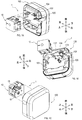
- FIG. 1A, 1B, and 1C are schematic perspective views showing a state in which the printing cassette is removed from the printing apparatus in the printing system according to the embodiment.
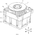
- 2A, 2B and 2C are schematic perspective views of a printing cassette in the printing system of FIG. 1A.
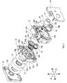
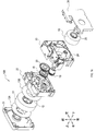
- FIG. 3 is a schematic exploded perspective view of the printing cassette of FIG. 2A.
- FIG. 4 is a schematic perspective view of the clutch in the printing cassette of FIG. 3A.
- 5A is a schematic cross-sectional view taken along the line VV of FIG. 2A, and FIG. 5B is a partially enlarged view of FIG. 5A.
- FIG. 6 is a schematic perspective view showing a state in which the first lid portion of the printing cassette of FIG. 2A is removed.
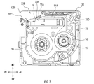
- FIG. 7 is a schematic view illustrating the paths of the tape to be printed and the ink ribbon in the printing cassette of FIG. 2A.
- 8A is a schematic cross-sectional view taken along the line VIIIA-VIIIA of FIG. 2C
- FIG. 8B is a schematic cross-sectional view taken along the line VIIIB-VIIIB of FIG. 2C
- FIG. 8C is a schematic cross-sectional view taken along the line VIIIB-VIIIB of FIG. 2C.
- FIG. 8D is a schematic cross-sectional view taken along the line VIIID-VIIID of FIG. 2C.
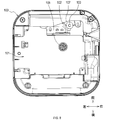
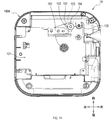
- FIG. 9 is a schematic plan view of the printing apparatus in the printing system of FIG. 1A.
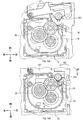
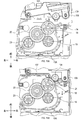
- FIG. 10A is a schematic view showing a separated state between the output gear and the platen gear in the printing system of FIG. 1A
- FIG. 10B is a schematic view showing an engaged state of the output gear and the platen gear in the printing system of FIG. 1A
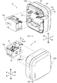
- .. 11A and 11B are schematic perspective views showing a state in which the printing cassette is removed from the printing apparatus in the printing system according to the embodiment different from that of FIG. 1A.
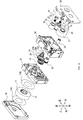
- FIG. 12 is a schematic exploded perspective view of the printing cassette in the printing system of FIG. 11A.
- 13A is a schematic cross-sectional view taken along the line XIIIA-XIIIA of FIG. 11B
- FIG. 13B is a partially enlarged view of FIG. 13A.
- FIG. 14 is a schematic plan view of the printing apparatus in the printing system of FIG. 11A.
- FIG. 15A is a schematic view showing a separated state between the output gear and the platen gear in the printing system of FIG. 11A
- FIG. 15B is a schematic diagram showing an engaged state of the output gear and the platen gear in the printing system of FIG. 11A.
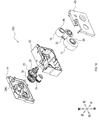
- FIG. 16 is a schematic exploded perspective view of a printing cassette of a printing system according to an embodiment different from FIGS. 1A and 11A
- FIG. 17 is a schematic exploded perspective view of a printing cassette of a printing system according to an embodiment different from FIGS. 1A, 11A and 16.
- FIG. 18 is a schematic exploded perspective view of a printing cassette of a printing system according to an embodiment different from FIGS. 1A, 11A, 16 and 17.
- the printing system 1 shown in FIGS. 1A, 1B, and 1C includes a printing cassette 10 and a printing device 100.
- the printing system 1 is a device that prints on a tape-shaped printing medium.
- the axial direction of the output gear 18 is the vertical direction
- the direction in which the output gear 18 and the input spool 16 are lined up is the front-rear direction among the directions perpendicular to the vertical direction, and is perpendicular to both the vertical direction and the front-rear direction.
- the print cassette 10 stores a print medium.
- the printing cassette 10 is removable from the printing device 100. By exchanging the printing cassette 10, the printing medium can be replenished and the type (for example, color, material, etc.) of the printing medium can be changed.
- the printing cassette 10 includes a case 35 for storing a tape to be printed, an ink ribbon, and the like, which will be described later.
- the outer shape of the printing cassette 10 (that is, the shape of the case 35) is a rectangular parallelepiped having a side parallel to the vertical direction, a side parallel to the front-rear direction, and a side parallel to the left-right direction.
- the case 35 is configured to be mounted downward with respect to the printing device 100.
- the case 35 has a first lid portion 31, a first case portion 32, a second case portion 33, and a second lid portion 34.
- the printing cassette 10 includes a tape roll 11 to be printed, a first supply spool 12, spacer films 13A and 13B, an ink ribbon roll 14, a second supply spool 15, and an input spool 16. (An example of a rotating spool), a clutch 17, an output gear 18, an input gear 19, and an idle gear 20 are provided.
- the tape to be printed roll 11 is obtained by winding the tape to be printed to be printed on the first supply spool 12. Printing is performed on the surface of the tape to be printed by the print head 102 and the ink ribbon of the printing apparatus 100 described later.
- Two spacer films 13A and 13B are arranged on the outside of the tape roll 11 to be printed in the vertical direction so as to sandwich the tape roll 11 to be printed.
- the spacer films 13A and 13B are arranged between the tape roll 11 to be printed and the first lid portion 31 and between the tape roll 11 to be printed and the first case portion 32.
- the first supply spool 12 is rotatable around a rotation axis.
- the first supply spool 12 supplies the tape to be printed to the print head 102 by rotating along with the transfer of the tape to be printed by the platen roller 103 of the printing apparatus 100 described later.
- the ink ribbon roll 14 is formed by winding an ink ribbon used for printing a tape to be printed on a second supply spool 15.
- the ink ribbon is overlapped with the tape to be printed at the head opening 33B described later, and is used for printing by the print head 102.
- the ink ribbon used for printing is wound around an input spool 16 described later.
- the second supply spool 15 is rotatable around a rotation axis.
- the rotation axis of the second supply spool 15 is parallel to the rotation axis of the first supply spool 12, that is, in the vertical direction.
- the second supply spool 15 sends out the ink ribbon from the ink ribbon roll 14 by rotating in the first rotation direction.
- the second supply spool 15 supplies the ink ribbon to the print head 102 by rotating along with the winding of the ink ribbon by the input spool 16. Further, at least a part of the second supply spool 15 is arranged at a position overlapping with the tape roll 11 to be printed in the vertical direction.
- the input spool 16 is rotatable around the axis of rotation.
- the rotation axis of the input spool 16 is parallel to the rotation axis of the second supply spool 15.
- the input spool 16 has a cylindrical shape and has a hollow portion defined by an inner peripheral surface 16A. Spline teeth 16B are provided on the inner peripheral surface 16A of the input spool 16. That is, the input spool 16 is an internal tooth gear.
- a drive shaft 105 of a printing device 100 which will be described later, is connected to the spline teeth 16B. The input spool 16 is rotated by the drive shaft 105 to wind up the ink ribbon.
- the clutch 17 has a spring holder 71 and a clutch spring 72.
- the spring holder 71 is rotatable around the center of rotation.
- the spring holder 71 has a first cylindrical portion 71A, a second cylindrical portion 71B, and a protrusion 71C.
- the outer diameter of the second cylindrical portion 71B is smaller than that of the first cylindrical portion 71A.
- the central axis of the second cylindrical portion 71B is arranged on the same straight line as the central axis of the first cylindrical portion 71A.
- the protrusion 71C projects radially outward from the first cylindrical portion 71A from the outer peripheral surface of the first cylindrical portion 71A.
- the clutch spring 72 has a coil portion 72A, a first engaging portion 72B, and a second engaging portion 72C.
- the coil portion 72A is composed of a linear body spirally wound around the outer peripheral surface of the second cylindrical portion 71B.
- Each of the first engaging portion 72B and the second engaging portion 72C is configured such that the end portion of the linear body forming the coil portion 72A projects outward in the radial direction of the second cylindrical portion 71B. ..
- the clutch 17 is arranged in the hollow portion of the second supply spool 15.
- the rotation axis of the clutch 17 is arranged on the same straight line as the rotation axis of the second supply spool 15.
- the second cylindrical portion 71B of the spring holder 71 and the coil portion 72A of the clutch spring 72 are arranged inside a plurality of convex portions 33F of the second case portion 33, which will be described later.
- the first engaging portion 72B and the second engaging portion 72C of the clutch spring 72 are engaged with the convex portion 33F.
- the protrusion 71C (see FIG. 4) of the spring holder 71 is engaged with a groove formed on the inner peripheral surface of the second supply spool 15. Therefore, the spring holder 71 rotates around the rotation axis of the second supply spool 15 together with the second supply spool 15.
- the rotation of the second supply spool 15 is resisted by the sliding friction between the second cylindrical portion 71B of the spring holder 71 and the coil portion 72A of the clutch spring 72. That is, the clutch 17 attaches a rotation resistance to the ink ribbon roll 14.
- the torque for feeding (that is, winding) the ink ribbon can be set by the rotational resistance of the clutch 17.
- the coil portion 72A of the clutch spring 72 expands in diameter when the spring holder 71 rotates in the first rotation direction, and contracts in diameter when the spring holder 71 rotates in the second rotation direction opposite to the first rotation direction. It is wound around a spring holder 71.
- the output gear 18 shown in FIG. 3 is an output unit for outputting a driving force for conveying the tape to be printed to the outside.
- the output gear 18 is drive-connected to an input gear 19 which will be described later.
- the output gear 18 transmits a driving force to the platen roller 103 via the platen gear 104 of the printing device 100.
- the output gear 18 is an external gear having a disk rotating around the center of rotation and teeth provided on a surface parallel to the vertical direction of the disk.
- One surface (that is, the upper surface) perpendicular to the vertical direction of the disk of the output gear 18 faces the cover portion 32B of the case 35, which will be described later, in the vertical direction.
- a part of the other surface (that is, the lower surface) perpendicular to the vertical direction of the disk does not face the case 35 in the vertical direction.
- a part of the output gear 18 is exposed at the head opening 33B, and a part of the output gear 18 is located outside the case 35.
- the output gear 18 engages with the platen gear 104 at the head opening 33B in a state where the printing cassette 10 is mounted on the cassette mounting portion 101 of the printing device 100.
- the tape roll 11, the output gear 18, and the ink ribbon roll 14 are arranged side by side in the vertical direction in the order of the tape roll 11, the output gear 18, and the ink ribbon roll 14. ing. That is, the output gear 18 is located between the tape roll 11 to be printed and the ink ribbon roll 14 in the vertical direction.
- the input gear 19 is an input unit for indirectly engaging with the output gear 18 via an idle gear 20 described later and transmitting a driving force to the output gear 18.
- the input gear 19 engages with the drive shaft 105 while the printing cassette 10 is mounted on the cassette mounting portion 101 of the printing device 100 described later.
- the driving force from the driving source of the printing apparatus 100 is input to the input gear 19 via the driving shaft 105.
- the input gear 19 has an external tooth gear 19A and a cylindrical internal tooth gear 19B.
- the entire external tooth gear 19A and the entire internal tooth gear 19B are housed in the case 35, respectively. That is, the entire input gear 19 is housed in the case 35.
- the external tooth gear 19A rotates integrally with the internal tooth gear 19B by the driving force input to the internal tooth gear 19B.
- the internal tooth gear 19B is fixed to the lower surface of the external tooth gear 19A and has spline teeth on the inner peripheral surface.
- the rotation axis of the input gear 19 (that is, the rotation axis of the external gear 19A and the rotation axis of the internal gear 19B) is arranged on the same line as the rotation axis of the input spool 16.
- the input spool 16, the input gear 19, and the tape roll 11 to be printed are arranged side by side in the vertical direction in the order of the input spool 16, the input gear 19, and the tape roll 11 to be printed.
- the input gear 19 is located between the input spool 16 and the tape roll 11 to be printed in the vertical direction. Further, at least a part of the input gear 19 is arranged at a position overlapping with the tape roll 11 to be printed in the vertical direction.
- the rotation axis of the input gear 19 passes through the hollow portion of the input spool 16. That is, the drive shaft 105 is inserted into the input spool 16 and the input gear 19 at the same time. As a result, the input gear 19 is not directly connected to the input spool 16, but is rotated by a drive source (that is, a drive shaft 105) common to the input spool 16.
- a drive source that is, a drive shaft 105
- the idle gear 20 is a transmission gear that is drive-connected (that is, engaged) with the input gear 19 and the output gear 18 and transmits the driving force input to the input gear 19 to the output gear 18.
- the idle gear 20 is a stage gear in which the first gear 20A engaged with the input gear 19 and the second gear 20B engaged with the output gear 18 are arranged coaxially.
- the diameter of the second gear 20B is smaller than that of the first gear 20A.
- the second gear 20B is arranged at a position (that is, above) closer to the tape roll 11 to be printed than the first gear 20A in the vertical direction.
- the idle gear 20 constitutes a reduction mechanism for decelerating the driving force input to the input gear 19.
- the first lid portion 31 constitutes the upper end portion of the printing cassette 10.
- the first case portion 32 is arranged below the first lid portion 31 and is connected to the first lid portion 31 in the vertical direction.
- the second case portion 33 is arranged below the first case portion 32 and is connected to the first case portion 32 in the vertical direction.
- the second lid portion 34 constitutes the lower end portion of the printing cassette 10.
- the second lid portion 34 is vertically connected to the second case portion 33.
- the first lid portion 31 and the first case portion 32 house the tape roll 11 to be printed. That is, the tape roll 11 to be printed is arranged in a space surrounded by the first lid portion 31 and the first case portion 32.
- the second lid portion 34 and the second case portion 33 house the ink ribbon roll 14, the second supply spool 15, and the input spool 16. That is, the ink ribbon roll 14, the second supply spool 15, and the input spool 16 are arranged in a space surrounded by the second lid portion 34 and the second case portion 33.
- the first case portion 32 and the second case portion 33 are connected to each other. A part of the output gear 18, the input gear 19, and the idle gear 20 are arranged in a space surrounded by the first case portion 32 and the second case portion 33.
- the first case portion 32 has a first side wall portion 32A, a cover portion 32B, a first guide 32C, a first shaft portion 32D, a second shaft portion 32E, a third shaft portion 32F, and an inner wall 32G. ..
- the first side wall 32A constitutes a side surface parallel to the vertical direction of the printing cassette 10.
- the cover portion 32B is a portion having a surface perpendicular to the vertical direction.
- the cover portion 32B is arranged at a position where it overlaps with the output gear 18 in the vertical direction.
- the cover portion 32B is provided continuously with the lower end portion of the first side wall 32A, and is arranged at the right front corner portion of the first case portion 32.
- the output gear 18, the cover portion 32B, and the tape roll 11 to be printed are arranged side by side in the vertical direction in the order of the output gear 18, the cover portion 32B, and the tape roll 11 to be printed. Further, as described above, the entire area of the upper surface of the output gear 18 is covered by the cover portion 32B.
- the first guide 32C is a portion around which the printed tape 11A drawn from the printed tape roll 11 is wound.
- the first guide 32C has a plurality of plate-shaped ribs arranged apart from each other along the circumferential direction of the tape roll 11 to be printed.
- the plurality of ribs project in the radial direction of the tape roll 11 to be printed, and the amount of protrusion (that is, the plate width) increases toward the lower side.
- the first shaft portion 32D shown in FIG. 3 rotatably supports the output gear 18 around a rotation axis parallel to the vertical direction.
- the second shaft portion 32E pivotally supports the input gear 19 so as to rotate around a rotation axis parallel to the vertical direction.
- the third shaft portion 32F pivotally supports the idle gear 20 so as to rotate around a rotation axis parallel to the vertical direction.
- the first shaft portion 32D, the second shaft portion 32E, and the third shaft portion 32F project from the inner wall 32G.
- the second case portion 33 has a second side wall 33A, a head opening 33B, a discharge port 33C, a second guide 33D, a protruding portion 33E, and a plurality of convex portions 33F.
- the second side wall 33A constitutes a side surface parallel to the vertical direction of the printing cassette 10.
- the head opening 33B is a portion cut out from a part of the second side wall 33A.
- the head opening 33B is a space in which the print head 102 is arranged by inserting the print head 102 from below with the print cassette 10 mounted on the printing device 100.
- the head opening 33B opens below the printing cassette 10.
- the second guide 33D is a portion around which the tape to be printed 11A that has passed through the first guide 32C is wound.
- the second guide 33D has a plurality of plate-shaped ribs arranged apart from each other along the circumferential direction of the ink ribbon roll 14. The plurality of ribs project in the radial direction of the ink ribbon roll 14, and the amount of protrusion (that is, the plate width) decreases toward the lower side.
- the protrusion 33E is arranged at a position where it overlaps with the output gear 18 in the vertical direction.
- the protrusion 33E is arranged on the lower side of the output gear 18 (that is, on the side opposite to the cover portion 32B with the output gear 18 interposed therebetween).
- the print head 102 of the printing device 100 is inserted in a region below the protrusion 33E. Therefore, in a state where the printing cassette 10 is mounted on the cassette mounting portion 101 of the printing apparatus 100, the output gear 18 is on the upstream side (that is, on the upstream side in the mounting direction of the printing cassette 10 on the cassette mounting portion 101) from the print head 102. Placed above).
- the plurality of convex portions 33F are arranged along the circumferential direction of the second cylindrical portion 71B of the clutch 17 so as to surround the second cylindrical portion 71B and the coil portion 72A of the clutch 17.
- the first engaging portion 72B and the second engaging portion 72C of the clutch spring 72 are inserted between the plurality of convex portions 33F, respectively.
- a fourth shaft portion 34A provided on the second lid portion 34 is inserted inside the first cylindrical portion 71A of the clutch 17.
- the second supply spool 15 is axially rotatably supported by the fourth shaft portion 34A via the first cylindrical portion 71A.
- the printing tape 11A and the ink ribbon 14A are bridged in the left-right direction at the head opening 33B.
- the printed tape 11A after printing is discharged to the outside of the printing system 1 from the discharge port 33C.
- the first guide 32C and the second guide 33D send the printed tape 11A constituting the printed tape roll 11 from the first case portion 32 to the second case portion 33. It constitutes a passage.
- the printed tape 11A drawn out from the printed tape roll 11 abuts on the first guide 32C in a spiral manner from the radial outside of the printed tape roll 11. It is conveyed downward and rearward within the first case portion 32.
- the tape to be printed 11A is conveyed downward to the left while straddling the connecting portion between the first case portion 32 and the second case portion 33 in the vertical direction.
- the printed tape 11A that has reached the second case portion 33 is conveyed downward and forward while abutting on the second guide 33D from the outside in the radial direction.
- the printed tape 11A that has reached the lower end of the printing cassette 10 passes through the head opening 33B and is discharged from the discharge port 33C.
- the printing apparatus 100 includes a cassette mounting portion 101, a printing head 102, a platen roller 103, a platen gear 104, a drive source (not shown), a drive shaft 105, and a movable portion 107. Be prepared.
- the cassette mounting portion 101 is a recess in which the printing cassette 10 can be mounted in the axial direction (that is, in the vertical direction) of the rotation axis of the drive shaft 105.
- the cassette mounting unit 101 has a positioning function for the printing cassette 10.
- the print head 102 is a device for printing on a printing tape held by the printing cassette 10.
- the print head 102 is arranged inside the cassette mounting portion 101.
- the print head 102 is arranged at a position where the printing cassette 10 is mounted on the printing apparatus 100 and overlaps with the tape to be printed and the ink ribbon in the front-rear direction in the head opening 33B.
- the print head 102 has a plurality of heat generating elements whose heat generation is individually controlled.
- the tape to be printed which is conveyed to the head opening 33B by the platen roller 103 described later, is pressed against the print head 102 where the heat generating element generates heat via the ink ribbon.
- the heat generating element generates heat via the ink ribbon.
- a part of the ink arranged on the surface of the ink ribbon is transferred to the printing tape, and characters, symbols, etc. are printed on the printing tape.
- the platen roller 103 is a roller for transporting the tape to be printed from the inside of the printing cassette 10 to the outside by the driving force transmitted from the output gear 18.
- the axis of rotation of the platen roller 103 is parallel to the vertical direction.
- the platen roller 103 is arranged inside the cassette mounting portion 101 so as to face the print head 102.
- the platen roller 103 abuts on the tape to be printed at the head opening 33B and presses the tape to be printed against the print head 102.
- the platen gear 104 is an external tooth gear that is driven and connected to the platen roller 103 and engages with the output gear 18.
- the rotation axis of the platen gear 104 is arranged on the same line as the rotation axis of the platen roller 103. Further, the platen gear 104 is arranged on the upstream side (that is, above) of the platen roller 103 in the mounting direction of the printing cassette 10 to the cassette mounting portion 101.
- the movable portion 107 is attached to the housing 110 so that it can swing in a plane perpendicular to the vertical direction.
- the platen roller 103 and the platen gear 104 are supported by the movable portion 107 so as to be swingable with respect to the housing 110.
- the platen roller 103 and the platen gear 104 swing between the position separated from the printing cassette 10 shown in FIG. 10A and the position where the platen gear 104 shown in FIG. 10B engages with the output gear 18 due to the swing of the movable portion 107. It is movable.
- the drive shaft 105 shown in FIG. 1B is a shaft that is inserted into the input spool 16 and engages with the input gear 19 to rotate the input spool 16 and the input gear 19.
- the drive shaft 105 has external teeth that engage the spline teeth 16B of the input spool 16 and the internal gear 19B of the input gear 19.
- the drive shaft 105 is arranged inside the cassette mounting portion 101.
- the center of rotation of the drive shaft 105 is parallel to the vertical direction.
- the drive shaft 105 can rotate about a rotation axis by a drive source (for example, a motor).
- the drive source generates a driving force input to the printing cassette 10.
- the drive shaft 105 With the printing cassette 10 mounted on the cassette mounting portion 101, at least a part of the drive shaft 105 is arranged inside the input spool 16. In this state, the drive shaft 105 engages the input gear 19 and the platen gear 104 engages the output gear 18.
- the drive shaft 105 is inserted into the input spool 16 and the input gear 19 of the printing cassette 10, and the platen roller 103 and the platen gear 104 are swung toward the head opening 33B of the printing cassette 10 for printing.
- the cassette 10 is mounted on the printing apparatus 100.
- the output gear 18 is rotated by rotating the input gear 19 by the drive shaft 105 with the printing cassette 10 mounted, the platen gear 104 is rotated by the rotation of the output gear 18, and the platen roller 103 is rotated by the rotation of the platen gear 104. Rotates.
- M1 is in the same direction as the drive rotation direction S of the drive shaft 105.
- the direction M2 of the moment around the drive shaft 105 generated in the printing cassette 10 by the reaction force received by the output gear 18 from the platen gear 104 is the drive shaft 105. It is in the opposite direction to the drive rotation direction S of.
- the driving force is transmitted to the platen roller 103 only when the printing cassette 10 is mounted on the printing device 100. Therefore, it is possible to suppress the unexpected rotation of the platen roller 103 when the printing cassette 10 is not mounted.
- the input gear 19 has an internal tooth gear 19B that engages with the external teeth of the drive shaft 105, and the output gear 18 and the platen gear 104 are external tooth gears that engage with each other.
- the degree of freedom in arranging the gear trains in the printing device 100 can be increased.
- the driving force can be transmitted from one drive shaft 105 to the input spool 16 and the input gear 19 at different positions in the axial direction of the rotation axis of the input spool 16 (that is, the insertion direction of the drive shaft 105). .. Therefore, the driving force is input to both the input spool 16 and the input gear 19 while suppressing the increase in the size of the printing cassette 10 in the direction perpendicular to the insertion direction of the drive shaft 105 (that is, the front-rear direction and the left-right direction). it can.
- the winding torque of the ink ribbon can be adjusted by the (1f) clutch 17. Therefore, ink ribbons having different widths, thicknesses, materials, and the like can be arranged in the printing cassettes 10 having the same shape.
- the printing system 1A shown in FIGS. 11A and 11B includes a printing cassette 10A and a printing device 100A.
- the printing cassette 10A is the printing cassette 10 of the first embodiment to which the laminated tape roll 21, the additional spool 22, the additional gear 23, the pinch roller 24, and the second clutch 17A shown in FIG. 12 are added. Is.
- the printing cassette 10A has the input spool 16, the first lid portion 31, the first case portion 32, the second case portion 33, and the second lid portion 34 of the printing cassette 10 of the first embodiment, respectively.
- the supply spool 25, the first lid portion 36, the first case portion 37, the second case portion 38, and the second lid portion 39 are replaced.
- the third supply spool 25 is the same as the input spool 16 except that it does not have the spline teeth 16B.
- the first lid portion 36, the first case portion 37, the second case portion 38, and the second lid portion 39 are the first lid portion 31, the first case portion 32, the second case portion 33, and the second lid portion 34, respectively. Is stretched in the left-right direction. Since the other configurations of the printing cassette 10A are the same as those of the printing cassette 10 of the first embodiment except for the points described below, the description thereof will be omitted.
- the laminated tape roll 21 is formed by winding a laminated tape used for protecting a tape to be printed around a third supply spool 25.
- the laminated tape has an adhesive surface that is attached to the tape to be printed printed by the print head 102.
- the additional spool 22 can rotate around the center of rotation.
- the rotation axis of the additional spool 22 is parallel to the rotation axis of the second supply spool 15 (that is, in the vertical direction).
- the additional spool 22 is a take-up spool that winds up the ink ribbon by rotating the additional gear 23 described later.
- the additional gear 23 is connected to the additional spool 22 and is engaged with the idle gear 20.
- the additional gear 23 is rotated by the driving force input to the input gear 19 to rotate the additional spool 22.
- the additional gear 23 has an external tooth gear 23A, a plurality of convex portions 23B, and a shaft portion 23C.
- the external tooth gear 23A has a rotation axis parallel to the vertical direction.
- the plurality of convex portions 23B are arranged along the peripheral surface of the shaft portion 23C so as to surround the shaft portion 23C.
- the plurality of convex portions 23B and the shaft portion 23C project downward from the external tooth gear 23A.
- the pinch roller 24 is arranged downstream of the head opening 33B in the transport direction of the tape to be printed.
- the second clutch 17A drives and connects the input gear 19 to the additional spool 22. Specifically, the second clutch 17A drives and connects the additional gear 23, which is drive-connected to the input gear 19, and the additional spool 22.
- the second clutch 17A has a spring holder 71 similar to the clutch 17, and a clutch spring 72.
- the second cylindrical portion 71B and the coil portion 72A of the second clutch 17A are arranged inside the plurality of convex portions 23B of the additional gear 23. Further, a shaft portion 23C of the additional gear 23 is inserted inside the second cylindrical portion 71B.
- the first cylindrical portion 71A of the second clutch 17A is fixed to the inner peripheral surface of the additional spool 22.
- the first engaging portion and the second engaging portion (not shown) of the second clutch 17A are engaged with a plurality of convex portions 23B of the additional gear 23.
- a fifth shaft portion 39A provided on the second lid portion 39 is inserted inside the first cylindrical portion 71A of the second clutch 17A.
- the additional spool 22 is axially rotatably supported by the fifth shaft portion 39A via the first cylindrical portion 71A.
- Resistance is attached to the additional spool 22 by sliding friction between the second cylindrical portion 71B of the spring holder 71 of the second clutch 17A and the coil portion 72A of the clutch spring 72. That is, the second clutch 17A attaches a rotation resistance to the take-up spool of the ink ribbon.
- the torque for winding the ink ribbon can be set by the rotational resistance of the second clutch 17A.
- the laminated tape roll 21 is provided with a rotation resistance by the same clutch 17 as in the first embodiment.
- the printing device 100A is obtained by adding the pressing roller 106 shown in FIG. 12 to the printing device 100 of the first embodiment. Since the other configurations of the printing apparatus 100A are the same as those of the printing apparatus 100 of the first embodiment except for the points described below, the description thereof will be omitted.
- the pressing roller 106 is attached to the movable portion 107 and is configured to swing together with the platen roller 103 and the platen gear 104. That is, the pressing roller 106 can swing between a position separated from the printing cassette 10A shown in FIG. 15A and a position where the printing tape and the laminating tape are pressed together with the pinch roller 24 shown in FIG. 15B.
- the printing apparatus of the above embodiment is not limited to printing using an ink ribbon.
- the printing apparatus may print using a strip-shaped thermal paper as the tape to be printed.
- the printing cassette does not necessarily have to have an ink ribbon roll and a second supply spool.
- the printing tape roll 11 is replaced with a printing tape roll 51 of thermal paper, and the ink ribbon roll 14 is laminated with a laminating tape. It was replaced with a tape roll 52.
- the laminated tape roll 52 is wound around the third supply spool 25 of the second embodiment. Further, the printing cassette 10B includes the pinch roller 24 of the second embodiment, but does not include the second supply spool 15.
- the output unit that transmits the driving force to the platen roller is not limited to the gear.
- a roller or spool may be used as the output unit.
- the input unit into which the driving force from the driving source is input is not limited to the gear.
- a roller or spool may be used as the input unit.
- the laminated tape may be wound around an additional spool.
- the printing cassette 10C shown in FIG. 17 is a printing cassette 10A of the second embodiment in which a laminated tape roll 21 of a laminated tape is wound around an additional spool 22.
- the printing cassette 10C includes an input spool 16 of the first embodiment instead of the third supply spool 25 of the second embodiment.
- the input spool 16 is used as a take-up spool of the ink ribbon.
- the tape roll to be printed, the output gear, and the auxiliary tape roll (that is, the ink ribbon roll or the laminated tape roll) of the auxiliary tape used for printing or protecting the tape to be printed are in the vertical direction. It is not limited to those lined up in.
- the tape to be printed may be arranged so as to overlap the auxiliary tape roll in the direction perpendicular to the vertical direction.
- the printing cassette 10D shown in FIG. 18 replaces the first lid portion 36, the first case portion 37, the second case portion 38, and the second lid portion 39 in the printing cassette 10A of the second embodiment.
- the first case portion 41, the second case portion 42, and the lid portion 43 are used.
- the first case portion 41 is obtained by adjusting the length of the first case portion 37 in FIG. 12 in the left-right direction, and taking out a portion below the inner wall 32G.
- the second case portion 42 is obtained by adjusting the length of the second case portion 38 in FIG. 12 in the left-right direction.
- the lid portion 43 is obtained by adjusting the length of the second lid portion 39 in FIG. 12 in the left-right direction.
- a tape roll 11 to be printed is wound around the third supply spool 25 of the printing cassette 10D instead of the laminate tape roll 21.
- the ink ribbon is wound by the additional spool 22 as in the second embodiment.
- thermal paper may be used as the printing tape.
- the ink ribbon roll 14, the second supply spool 15, the additional spool 22, and the additional gear 23 are unnecessary, and the printing cassette 10D includes only the tape roll 11 to be printed as a roll.
- the printing cassette of the above embodiment may have two or more idle gears. That is, the printing cassette may have a transmission gear train that engages with the input gear. Further, the input gear and the output gear may be directly engaged with each other without interposing the idle gear.
Landscapes
- Impression-Transfer Materials And Handling Thereof (AREA)
- Handling Of Continuous Sheets Of Paper (AREA)
- Printers Characterized By Their Purpose (AREA)
- Replacement Of Web Rolls (AREA)
- Handling Of Sheets (AREA)
Abstract
Description
[1-1.構成]
図1A,1B,1Cに示す印刷システム1は、印刷用カセット10と、印刷装置100とを備える。印刷システム1は、テープ状の印刷媒体に印刷を行う装置である。
印刷用カセット10は、印刷媒体を格納している。印刷用カセット10は、印刷装置100に着脱可能である。印刷用カセット10の交換により、印刷媒体の補給、及び印刷媒体の種類(例えば、色、材質等)の変更ができる。
被印刷テープロール11は、印刷が行われる被印刷テープを第1供給スプール12に巻回したものである。被印刷テープの表面には、後述する印刷装置100の印刷ヘッド102及びインクリボンによって印刷が行われる。
第1供給スプール12は、回転軸心周りに回転可能である。第1供給スプール12は、後述する印刷装置100のプラテンローラ103による被印刷テープの搬送に伴って回転することで、被印刷テープを印刷ヘッド102に供給する。
インクリボンロール14は、被印刷テープの印刷に用いられるインクリボンを第2供給スプール15に巻回したものである。
第2供給スプール15は、回転軸心周りに回転可能である。第2供給スプール15の回転軸心は、第1供給スプール12の回転軸心、つまり上下方向と平行である。第2供給スプール15は、第1回転方向に回転することで、インクリボンロール14からインクリボンを送り出す。
入力スプール16は、回転軸心周りに回転可能である。入力スプール16の回転軸心は、第2供給スプール15の回転軸心と平行である。
クラッチ17は、図4に示すように、バネホルダ71と、クラッチバネ72とを有する。バネホルダ71は、回転軸心周りに回転可能である。
図3に示す出力ギア18は、被印刷テープを搬送するための駆動力を外部に出力するための出力部である。出力ギア18は、後述する入力ギア19と駆動連結されている。出力ギア18は、印刷装置100のプラテンギア104を介して、プラテンローラ103に駆動力を伝達する。
図3に示すように、入力ギア19は、後述するアイドルギア20を介して出力ギア18と間接的に係合し、駆動力を出力ギア18に伝達するための入力部である。
アイドルギア20は、入力ギア19と出力ギア18とに駆動連結され(つまり係合し)、入力ギア19に入力された駆動力を出力ギア18に伝達する伝達ギアである。
第1蓋部31は、印刷用カセット10の上端部を構成している。第1ケース部32は、第1蓋部31の下側に配置され、第1蓋部31と上下方向に連結されている。第2ケース部33は、第1ケース部32の下側に配置され、第1ケース部32と上下方向に連結されている。第2蓋部34は、印刷用カセット10の下端部を構成している。第2蓋部34は、第2ケース部33と上下方向に連結されている。
印刷装置100は、図1Bに示すように、カセット装着部101と、印刷ヘッド102と、プラテンローラ103と、プラテンギア104と、駆動源(図示省略)と、駆動シャフト105と、可動部107とを備える。
カセット装着部101は、印刷用カセット10が駆動シャフト105の回転軸心の軸方向(つまり上下方向)に装着可能な凹部である。カセット装着部101は、印刷用カセット10の位置決め機能を有する。
印刷ヘッド102は、印刷用カセット10が保持する被印刷テープに印刷するための装置である。
プラテンローラ103は、出力ギア18から伝達される駆動力によって被印刷テープを印刷用カセット10内から外部に向けて搬送するためのローラである。プラテンローラ103の回転軸心は、上下方向と平行である。
プラテンギア104は、プラテンローラ103に駆動連結され、出力ギア18と係合する外歯ギアである。
可動部107は、上下方向と垂直な面内で揺動可能なように筐体110に取り付けられている。プラテンローラ103及びプラテンギア104は、可動部107に支持されることにより、筐体110に対して揺動可能に構成されている。
図1Bに示す駆動シャフト105は、入力スプール16に挿入されると共に入力ギア19に係合し、入力スプール16と入力ギア19とを回転させるためのシャフトである。駆動シャフト105は、入力スプール16のスプライン歯16B及び入力ギア19の内歯ギア19Bと係合する外歯を有する。
以上詳述した実施形態によれば、以下の効果が得られる。
(1a)印刷装置100の駆動源からの駆動力が印刷用カセット10内の入力ギア19及び出力ギア18を介してプラテンローラ103に伝達される。
[2-1.構成]
図11A,11Bに示す印刷システム1Aは、印刷用カセット10Aと、印刷装置100Aとを備える。
印刷用カセット10Aは、第1実施形態の印刷用カセット10に、図12に示すラミネートテープロール21と、追加スプール22と、追加ギア23と、ピンチローラ24と、第2クラッチ17Aを追加したものである。
印刷装置100Aは、第1実施形態の印刷装置100に、図12に示される押圧ローラ106を追加したものである。印刷装置100Aのその他の構成は、以下に説明する点を除き、第1実施形態の印刷装置100と同じであるため、説明を省略する。
以上詳述した実施形態によれば、以下の効果が得られる。
(2a)第1実施形態と同様の利点を有したまま、ラミネートテープによって被印刷テープの印刷内容を保護することができる。
以上、本開示の実施形態について説明したが、本開示は、上記実施形態に限定されることなく、種々の形態を採り得ることは言うまでもない。
12…第1供給スプール、14…インクリボンロール、15…第2供給スプール、 16…入力スプール、17,17A…クラッチ、18…出力ギア、19…入力ギア、 19A…外歯ギア、19B…内歯ギア、20…アイドルギア、
21…ラミネートテープロール、22…追加スプール、23…追加ギア、
24…ピンチローラ、25…第3供給スプール、31…第1蓋部、
32…第1ケース部、33…第2ケース部、33B…ヘッド開口、34…第2蓋部、 35…ケース、71…バネホルダ、72…クラッチバネ、100…印刷装置、 101…カセット装着部、102…印刷ヘッド、103…プラテンローラ、
104…プラテンギア、105…駆動シャフト、107…可動部。
Claims (21)
- 印刷ヘッドと、
前記印刷ヘッドに対向するプラテンローラと、
駆動源と、
前記駆動源に駆動連結され、回転軸心周りに回転可能な駆動シャフトと、
前記プラテンローラに駆動連結されたプラテンギアと、
前記印刷ヘッド及び前記駆動シャフトが配置されたカセット装着部と、
を備え、
前記カセット装着部は、被印刷テープ、入力部、及び前記入力部と駆動連結された出力部を有する印刷用カセットが前記駆動シャフトの前記回転軸心の軸方向に装着可能であり、
前記印刷用カセットが前記カセット装着部に装着された状態で、前記駆動シャフトは前記入力部と係合し、前記プラテンギアは前記出力部と係合する、印刷装置。 - 前記駆動シャフト、前記プラテンギア、及び前記出力部は、それぞれ、外歯を有し、 前記入力部は、内歯を有する、請求項1に記載の印刷装置。
- 前記プラテンギアは、前記プラテンローラよりも前記印刷用カセットの前記カセット装着部への装着方向における上流側に配置される、請求項1又は請求項2に記載の印刷装置。
- 前記プラテンギアの回転軸心と前記プラテンローラの回転軸心とは、同一直線上に位置する、請求項1から請求項3のいずれか1項に記載の印刷装置。
- 前記印刷用カセットが前記カセット装着部に装着された状態で、前記駆動シャフトの少なくとも一部は、前記印刷用カセットが有する回転スプールの内部に配置される、請求項1から請求項4のいずれか1項に記載の印刷装置。
- 前記印刷用カセットが前記カセット装着部に装着された状態で、前記プラテンローラが前記被印刷テープを搬送することによって前記印刷用カセットに発生する前記駆動シャフト周りのモーメントの方向は、前記駆動シャフトの回転方向と同じであり、
前記印刷用カセットが前記カセット装着部に装着された状態で、前記出力部が前記プラテンギアから受ける反力によって前記印刷用カセットに発生する前記駆動シャフト周りのモーメントの方向は、前記駆動シャフトの回転方向と逆である、請求項1から請求項5のいずれか1項に記載の印刷装置。 - 前記プラテンギアは、前記印刷用カセットが前記カセット装着部に装着された状態で、前記出力部と離間した位置と、前記出力部に係合した位置との間で揺動可能である、請求項1から請求項6のいずれか1項に記載の印刷装置。
- 印刷ヘッドと、前記印刷ヘッドに対向するプラテンローラと、駆動源と、前記駆動源に駆動連結され、回転軸心周りに回転可能な駆動シャフトと、前記プラテンローラに駆動連結されたプラテンギアと、前記印刷ヘッド及び前記駆動シャフトが配置されたカセット装着部とを備える印刷装置に、前記駆動シャフトの前記回転軸心の軸方向に装着可能な印刷用カセットであって、
被印刷テープと、
入力部と、
前記入力部と駆動連結された出力部と、
を備え、
前記カセット装着部に装着された状態で、前記入力部は前記駆動シャフトと係合し、前記出力部は前記プラテンギアと係合する、印刷用カセット。 - 前記出力部は、外歯ギアを有し、
前記入力部は、第1内歯ギアを有する、請求項8に記載の印刷用カセット。 - 回転スプールをさらに備え、
前記回転スプールの回転軸心と前記第1内歯ギアの回転軸心とは同一線上に位置する、請求項9に記載の印刷用カセット。 - 前記回転スプールは、第2内歯ギアを有する、請求項10に記載の印刷用カセット。
- 前記被印刷テープの少なくとも一部、前記入力部の全体、及び前記出力部の少なくとも一部が収納されるケースをさらに備え、
前記出力部の一部は、前記ケースの外に位置する、請求項8から請求項11のいずれか1項に記載の印刷用カセット。 - インクリボンと、
前記インクリボンを巻き取る巻取スプールと、
をさらに備え、
前記入力部は、前記巻取スプールに駆動連結される、請求項8から請求項12のいずれか1項に記載の印刷用カセット。 - 前記入力部を前記巻取スプールに駆動連結するクラッチをさらに備える、請求項13に記載の印刷用カセット。
- 前記カセット装着部に装着された状態で、前記出力部は、前記印刷ヘッドよりも前記カセット装着部への装着方向における上流側に配置される、請求項8から請求項14のいずれか1項に記載の印刷用カセット。
- ケースと、
前記ケースに少なくとも一部が収納される被印刷テープと、
第1内歯ギアと第1外歯ギアとを有する第1ギアと、
前記第1外歯ギアと係合する伝達ギア又は伝達ギア列と、
前記伝達ギア又は前記伝達ギア列と係合する第2外歯ギアを有する第2ギアと、 を備え、
前記第1内歯ギアの全体は、前記ケースに収納され、
前記第2外歯ギアの一部は、前記ケースの外に位置する、印刷用カセット。 - 前記第1外歯ギアの全体は、前記ケースに収納される、請求項16に記載の印刷用カセット。
- 回転スプールをさらに備え、
前記回転スプールの回転軸心と前記第1内歯ギアの回転軸心とは同一線上に位置する、請求項16又は請求項17に記載の印刷用カセット。 - 前記回転スプールは、第2内歯ギアを有する、請求項18に記載の印刷用カセット。
- インクリボンと、
前記インクリボンを巻き取る巻取スプールと、
をさらに備え、
前記第1ギアは、前記巻取スプールに駆動連結される、請求項16から請求項19のいずれか1項に記載の印刷用カセット。 - 前記第1ギアを前記巻取スプールに駆動連結するクラッチをさらに備える、請求項20に記載の印刷用カセット。
Priority Applications (10)
| Application Number | Priority Date | Filing Date | Title |
|---|---|---|---|
| CA3156251A CA3156251A1 (en) | 2019-09-30 | 2020-09-15 | Printer and printing cassette |
| ES20871133T ES3048111T3 (en) | 2019-09-30 | 2020-09-15 | Printing device and printing cassette |
| CN202411281125.6A CN119078382A (zh) | 2019-09-30 | 2020-09-15 | 打印设备和打印用带盒 |
| EP20871133.3A EP4019261B1 (en) | 2019-09-30 | 2020-09-15 | Printing device and printing cassette |
| PL20871133.3T PL4019261T3 (pl) | 2019-09-30 | 2020-09-15 | Urządzenie drukujące i kaseta drukująca |
| CN202411281109.7A CN119159918A (zh) | 2019-09-30 | 2020-09-15 | 打印设备和打印用带盒 |
| CN202080067936.XA CN114502384B (zh) | 2019-09-30 | 2020-09-15 | 打印设备和打印用带盒 |
| EP25195522.5A EP4628439A3 (en) | 2019-09-30 | 2020-09-15 | Printer and printing cassette |
| US17/705,275 US12214586B2 (en) | 2019-09-30 | 2022-03-26 | Printer and printing cassette |
| US19/002,592 US20250332851A1 (en) | 2019-09-30 | 2024-12-26 | Printer and printing cassette |
Applications Claiming Priority (2)
| Application Number | Priority Date | Filing Date | Title |
|---|---|---|---|
| JP2019-178163 | 2019-09-30 | ||
| JP2019178163A JP7322638B2 (ja) | 2019-09-30 | 2019-09-30 | 印刷装置及び印刷用カセット |
Related Child Applications (1)
| Application Number | Title | Priority Date | Filing Date |
|---|---|---|---|
| US17/705,275 Continuation US12214586B2 (en) | 2019-09-30 | 2022-03-26 | Printer and printing cassette |
Publications (1)
| Publication Number | Publication Date |
|---|---|
| WO2021065477A1 true WO2021065477A1 (ja) | 2021-04-08 |
Family
ID=75271973
Family Applications (1)
| Application Number | Title | Priority Date | Filing Date |
|---|---|---|---|
| PCT/JP2020/034877 Ceased WO2021065477A1 (ja) | 2019-09-30 | 2020-09-15 | 印刷装置及び印刷用カセット |
Country Status (8)
| Country | Link |
|---|---|
| US (2) | US12214586B2 (ja) |
| EP (2) | EP4628439A3 (ja) |
| JP (3) | JP7322638B2 (ja) |
| CN (3) | CN114502384B (ja) |
| CA (1) | CA3156251A1 (ja) |
| ES (1) | ES3048111T3 (ja) |
| PL (1) | PL4019261T3 (ja) |
| WO (1) | WO2021065477A1 (ja) |
Cited By (1)
| Publication number | Priority date | Publication date | Assignee | Title |
|---|---|---|---|---|
| WO2024080162A1 (ja) * | 2022-10-11 | 2024-04-18 | ブラザー工業株式会社 | 印刷用カセット |
Families Citing this family (5)
| Publication number | Priority date | Publication date | Assignee | Title |
|---|---|---|---|---|
| JP2024056471A (ja) * | 2022-10-11 | 2024-04-23 | ブラザー工業株式会社 | 印刷用カセット及び印刷装置 |
| JP2025033080A (ja) * | 2023-08-29 | 2025-03-13 | 京楽産業.株式会社 | 遊技機 |
| JP2025033079A (ja) * | 2023-08-29 | 2025-03-13 | 京楽産業.株式会社 | 遊技機 |
| JP2025033078A (ja) * | 2023-08-29 | 2025-03-13 | 京楽産業.株式会社 | 遊技機 |
| EP4729302A1 (en) * | 2024-10-16 | 2026-04-22 | Seiko Epson Corporation | Ink ribbon cartridge |
Citations (6)
| Publication number | Priority date | Publication date | Assignee | Title |
|---|---|---|---|---|
| JP2000006504A (ja) * | 1998-06-24 | 2000-01-11 | Casio Comput Co Ltd | テープ巻取装置 |
| JP2010234772A (ja) | 2009-03-31 | 2010-10-21 | Brother Ind Ltd | テープカセットおよびテープ印字装置 |
| JP2011046142A (ja) * | 2009-08-28 | 2011-03-10 | Brother Industries Ltd | テープカセットと印字装置 |
| JP2012158175A (ja) * | 2012-03-12 | 2012-08-23 | Brother Industries Ltd | テープカセットおよびテープ印字装置 |
| JP2012236307A (ja) * | 2011-05-11 | 2012-12-06 | Fujicopian Co Ltd | 印字装置のインクリボンカセット |
| JP2015182318A (ja) * | 2014-03-24 | 2015-10-22 | セイコーエプソン株式会社 | テープカートリッジおよびテープ印刷装置 |
Family Cites Families (96)
| Publication number | Priority date | Publication date | Assignee | Title |
|---|---|---|---|---|
| JPS5036734B1 (ja) | 1970-04-13 | 1975-11-27 | ||
| SE364584B (ja) | 1970-04-13 | 1974-02-25 | Canon Kk | |
| US3672603A (en) | 1970-06-26 | 1972-06-27 | Cartridge Television Inc | Tape cartridge |
| US3804227A (en) | 1972-05-03 | 1974-04-16 | Scm Corp | Typewriter ribbon cartridge |
| US3948382A (en) | 1973-01-29 | 1976-04-06 | The Singer Company | Data terminal printing assembly |
| US4034935A (en) | 1975-11-19 | 1977-07-12 | Xerox Corporation | Dual level ribbon cartridge |
| CA1119549A (en) | 1978-01-30 | 1982-03-09 | Collier M. Miller | Ribbon cartridge drive |
| US4252450A (en) | 1978-10-03 | 1981-02-24 | Xerox Corporation | Ribbon drive with spring-loaded idler |
| US4397574A (en) | 1979-10-29 | 1983-08-09 | Ncr Corporation | Reloadable ribbon cassette |
| GB2064476B (en) | 1979-11-29 | 1983-08-10 | Itt Creed | Ink ribbon cassette |
| NL8200181A (nl) | 1981-01-31 | 1982-08-16 | Victor Company Of Japan | Registreer- en /of reproduceerinrichting. |
| US4402619A (en) | 1981-03-30 | 1983-09-06 | Kroy, Inc. | Printing apparatus and printing cartridge therefor |
| JPS58122887A (ja) | 1982-01-18 | 1983-07-21 | Silver Seiko Ltd | タイプライタ−のモ−タ駆動装置 |
| JPS58141479A (ja) | 1982-02-15 | 1983-08-22 | Canon Inc | カセツト |
| JPS58175949U (ja) | 1982-05-20 | 1983-11-25 | 大和製衡株式会社 | ラベルプリンタ |
| FR2528929B1 (fr) | 1982-06-17 | 1988-04-08 | Sagem | Perfectionnements apportes a des dispositifs mecaniques d'entrainement selectif d'au moins deux arbres menes a partir d'un arbre menant unique, notamment pour le deplacement longitudinal d'un ruban encreur dans une machine imprimante |
| JPS5995180A (ja) | 1982-11-22 | 1984-06-01 | Matsushita Electric Ind Co Ltd | インクリボンカセツト |
| US4490059A (en) | 1983-05-04 | 1984-12-25 | Wordex | Ribbon metering device |
| US4856921A (en) | 1983-06-28 | 1989-08-15 | Alps Electric Co., Ltd. | Rotary wheel printer |
| JPS608072U (ja) | 1983-06-30 | 1985-01-21 | アルプス電気株式会社 | プリンタ |
| JPS609657U (ja) | 1983-07-01 | 1985-01-23 | アルプス電気株式会社 | プリンタ |
| DE3424045A1 (de) | 1983-06-30 | 1985-01-03 | Alps Electric Co., Ltd., Tokio/Tokyo | Typenraddrucker |
| JPS6036255U (ja) | 1983-08-22 | 1985-03-13 | 日本電産コパル株式会社 | 熱転写式シリアルプリンタ− |
| JPS6046254U (ja) | 1983-09-06 | 1985-04-01 | アルプス電気株式会社 | リボンカセツト |
| JPS6048456U (ja) | 1983-09-12 | 1985-04-05 | 株式会社東芝 | 熱転写形プリンタ |
| JPH0227613B2 (ja) | 1984-03-08 | 1990-06-19 | Teraoka Seiko Kk | Denshihakaryopurinta |
| US4598780A (en) | 1984-03-02 | 1986-07-08 | Teraoka Seiko Co., Ltd. | Electronic scale printer |
| US4668961A (en) | 1984-04-20 | 1987-05-26 | Canon Kabushiki Kaisha | Recording apparatus |
| JPS60224571A (ja) | 1984-04-20 | 1985-11-08 | Canon Inc | 転写記録装置 |
| JPS61154877A (ja) | 1984-12-27 | 1986-07-14 | Matsushita Electric Ind Co Ltd | リボンカセツト |
| JPH0761729B2 (ja) | 1985-10-30 | 1995-07-05 | 株式会社リコー | 印字装置のリボンカセツト |
| JPS63156762U (ja) | 1987-04-02 | 1988-10-14 | ||
| US4832514A (en) | 1988-02-01 | 1989-05-23 | Kroy Inc. | Thermal transfer device and tape-ribbon cartridge therefor |
| JPH029562U (ja) | 1988-06-22 | 1990-01-22 | ||
| JPH026173A (ja) | 1988-06-27 | 1990-01-10 | Canon Inc | リボン送り装置 |
| JPH0211379A (ja) | 1988-06-30 | 1990-01-16 | Canon Inc | インクリボンカセット |
| JPH0211380A (ja) | 1988-06-30 | 1990-01-16 | Canon Inc | インクリボンカセット |
| US5099378A (en) | 1989-08-24 | 1992-03-24 | Minnesota Mining And Manufacturing Company | Carrier with external interlock for videocassette |
| IT218846Z2 (it) | 1989-11-16 | 1992-11-05 | Incas Holding Spa | Notarbartolo & gervasi |
| US5234179A (en) | 1990-02-20 | 1993-08-10 | Minnesota Mining And Manufacturing Company | Videotape adaptor for use with a cartridge |
| JPH03284973A (ja) | 1990-04-02 | 1991-12-16 | Canon Inc | リボンカセット及び前記リボンカセットを用いる記録装置 |
| JPH04152176A (ja) | 1990-10-16 | 1992-05-26 | Nec Corp | プリンタのインクリボンカセット |
| JPH0553956A (ja) | 1991-08-29 | 1993-03-05 | Mitsubishi Electric Corp | コンピユータ通信網構成支援システム |
| JPH0541834U (ja) | 1991-11-11 | 1993-06-08 | フジコピアン株式会社 | インクリボンカセツト |
| JPH0553956U (ja) | 1991-12-24 | 1993-07-20 | 日本電気ホームエレクトロニクス株式会社 | インクリボンカセット |
| US5325114A (en) | 1992-09-24 | 1994-06-28 | Pitney Bowes Inc. | Thermal printing postage meter system |
| JP2995314B2 (ja) * | 1992-10-15 | 1999-12-27 | カシオ計算機株式会社 | テープカセットおよび印字装置 |
| JP3341052B2 (ja) | 1993-06-28 | 2002-11-05 | カシオ計算機株式会社 | 印刷用カセット |
| JP2831237B2 (ja) | 1993-07-19 | 1998-12-02 | 富士通アイソテック株式会社 | インクリボンカセット |
| US5411339A (en) * | 1993-12-09 | 1995-05-02 | Kroy, Inc. | Portable printer and cartridge therefor |
| US5435657A (en) | 1993-12-28 | 1995-07-25 | Smith Corona Corporation | Label printer and tape and ink ribbon cartridge for use therein |
| JPH07276755A (ja) | 1994-04-06 | 1995-10-24 | Casio Comput Co Ltd | 印刷用カセットおよび印刷装置 |
| JPH07276757A (ja) | 1994-04-11 | 1995-10-24 | Fujicopian Co Ltd | 転写リボンカセット |
| US5619244A (en) | 1994-12-27 | 1997-04-08 | Pitney Bowes Inc. | Thermal ink cassette for a thermal printing device |
| JP3113532B2 (ja) | 1994-12-28 | 2000-12-04 | アルプス電気株式会社 | テープカセット |
| JPH08183205A (ja) | 1994-12-28 | 1996-07-16 | Alps Electric Co Ltd | テープ印字装置 |
| JP3160173B2 (ja) | 1994-12-28 | 2001-04-23 | アルプス電気株式会社 | テープ印字装置 |
| US5917532A (en) | 1996-11-29 | 1999-06-29 | Pitney Bowes Inc. | Thermal ink ribbon cassette for mailing machines |
| US5959652A (en) | 1997-07-11 | 1999-09-28 | Pitney Bowes Inc. | Thermal ink ribbon cassette for mailing machines |
| US6190067B1 (en) * | 1998-09-21 | 2001-02-20 | Casio Computer., Ltd. | Cassette containing magnetically affixable printing tape |
| US6341906B2 (en) * | 1998-09-21 | 2002-01-29 | Casio Computer Co., Ltd. | Cassette containing magnetically affixable printing tape and tape printer which use the cassette |
| JP4174873B2 (ja) | 1998-09-29 | 2008-11-05 | ブラザー工業株式会社 | テープカセット |
| FR2796372B1 (fr) | 1999-07-13 | 2001-09-07 | Dassault Automatismes | Cassette a ruban consommable, notamment pour dispositif de traitement de titres de transport |
| JP2001047713A (ja) | 1999-08-05 | 2001-02-20 | Fujicopian Co Ltd | インクリボンカセット |
| JP4574869B2 (ja) | 2001-01-18 | 2010-11-04 | 日本電産コパル株式会社 | サーマルプリンタ |
| US7070347B2 (en) | 2003-08-12 | 2006-07-04 | Brady Worldwide, Inc. | Printer with a pivoting gear mechanism |
| JP2006110811A (ja) * | 2004-10-13 | 2006-04-27 | Casio Comput Co Ltd | 印字装置 |
| US7484902B2 (en) | 2006-01-24 | 2009-02-03 | Cartec International, Inc. | Ribbon cassette for mailing machine |
| US20080084494A1 (en) | 2006-03-23 | 2008-04-10 | Cartec International, Inc. | Ribbon cassette for mailing machine |
| JP4337902B2 (ja) | 2007-04-11 | 2009-09-30 | コニカミノルタビジネステクノロジーズ株式会社 | トナー収容容器及びそれに適した画像形成装置 |
| JP5082916B2 (ja) | 2008-02-25 | 2012-11-28 | セイコーエプソン株式会社 | 収容体及び記録装置 |
| PT2370265E (pt) | 2008-12-25 | 2013-10-04 | Brother Ind Ltd | Cassete de fita e impressora de fita |
| BRPI0923680B1 (pt) | 2008-12-25 | 2020-01-28 | Brother Kogyo Kabushiki Kaisha | fita cassete |
| EP4067095B1 (en) | 2009-03-31 | 2025-08-20 | Brother Kogyo Kabushiki Kaisha | Tape cassette |
| DK2414165T3 (da) | 2009-03-31 | 2014-05-05 | Brother Ind Ltd | Båndkassette og båndprinter |
| CN104691118B (zh) | 2009-03-31 | 2017-10-13 | 兄弟工业株式会社 | 带盒 |
| WO2010113445A1 (en) | 2009-03-31 | 2010-10-07 | Brother Kogyo Kabushiki Kaisha | Tape cassette and tape printer |
| GB0907280D0 (en) * | 2009-04-28 | 2009-06-10 | Dymo Nv | Cassette for use in a tape printer |
| JP5482215B2 (ja) | 2010-01-19 | 2014-05-07 | コニカミノルタ株式会社 | 画像形成装置 |
| JP2011148167A (ja) | 2010-01-20 | 2011-08-04 | Oki Data Corp | インクリボンカートリッジ |
| US8395647B2 (en) | 2010-07-29 | 2013-03-12 | Brady Worldwide, Inc. | Printer with pivotable platen |
| CN102092201B (zh) | 2011-01-10 | 2012-03-07 | 珠海天威飞马打印耗材有限公司 | 色带盒 |
| JP6160126B2 (ja) | 2013-03-04 | 2017-07-12 | ブラザー工業株式会社 | 現像カートリッジ |
| CN104129176B (zh) * | 2013-05-02 | 2017-10-27 | 山东新北洋信息技术股份有限公司 | 纸仓、打印机和多类型介质的使用方法 |
| CN103273748B (zh) | 2013-06-07 | 2015-09-30 | 红石电脑(上海)有限公司 | 色带匣 |
| JP6381941B2 (ja) * | 2014-03-24 | 2018-08-29 | セイコーエプソン株式会社 | テープカートリッジ |
| EP3492268A1 (en) * | 2014-03-24 | 2019-06-05 | Seiko Epson Corporation | Tape printing device and tape printing system |
| CN106103118B (zh) | 2014-03-24 | 2018-09-28 | 精工爱普生株式会社 | 带打印装置和带打印系统 |
| JP6113207B2 (ja) | 2014-03-24 | 2017-04-12 | セイコーエプソン株式会社 | テープカートリッジ |
| JP6134283B2 (ja) * | 2014-03-24 | 2017-05-24 | セイコーエプソン株式会社 | テープカートリッジ |
| JP6374191B2 (ja) | 2014-03-24 | 2018-08-15 | セイコーエプソン株式会社 | テープカートリッジ |
| US9694599B2 (en) | 2014-03-24 | 2017-07-04 | Seiko Epson Corporation | Tape printing device and tape printing system |
| JP6100721B2 (ja) | 2014-03-24 | 2017-03-22 | セイコーエプソン株式会社 | テープカートリッジ |
| EP3323621B1 (en) * | 2015-07-13 | 2022-05-04 | Brother Kogyo Kabushiki Kaisha | Ribbon cassette |
| JP6524948B2 (ja) * | 2016-03-29 | 2019-06-05 | ブラザー工業株式会社 | 印字テープ及び印字カセット |
| JP2025182318A (ja) * | 2024-06-03 | 2025-12-15 | 株式会社三共 | 遊技機 |
-
2019
- 2019-09-30 JP JP2019178163A patent/JP7322638B2/ja active Active
-
2020
- 2020-09-15 CN CN202080067936.XA patent/CN114502384B/zh active Active
- 2020-09-15 EP EP25195522.5A patent/EP4628439A3/en active Pending
- 2020-09-15 EP EP20871133.3A patent/EP4019261B1/en active Active
- 2020-09-15 CA CA3156251A patent/CA3156251A1/en active Pending
- 2020-09-15 ES ES20871133T patent/ES3048111T3/es active Active
- 2020-09-15 WO PCT/JP2020/034877 patent/WO2021065477A1/ja not_active Ceased
- 2020-09-15 CN CN202411281109.7A patent/CN119159918A/zh active Pending
- 2020-09-15 CN CN202411281125.6A patent/CN119078382A/zh active Pending
- 2020-09-15 PL PL20871133.3T patent/PL4019261T3/pl unknown
-
2022
- 2022-03-26 US US17/705,275 patent/US12214586B2/en active Active
-
2023
- 2023-07-26 JP JP2023121497A patent/JP7635803B2/ja active Active
-
2024
- 2024-12-26 US US19/002,592 patent/US20250332851A1/en active Pending
-
2025
- 2025-02-12 JP JP2025020966A patent/JP7831660B2/ja active Active
Patent Citations (6)
| Publication number | Priority date | Publication date | Assignee | Title |
|---|---|---|---|---|
| JP2000006504A (ja) * | 1998-06-24 | 2000-01-11 | Casio Comput Co Ltd | テープ巻取装置 |
| JP2010234772A (ja) | 2009-03-31 | 2010-10-21 | Brother Ind Ltd | テープカセットおよびテープ印字装置 |
| JP2011046142A (ja) * | 2009-08-28 | 2011-03-10 | Brother Industries Ltd | テープカセットと印字装置 |
| JP2012236307A (ja) * | 2011-05-11 | 2012-12-06 | Fujicopian Co Ltd | 印字装置のインクリボンカセット |
| JP2012158175A (ja) * | 2012-03-12 | 2012-08-23 | Brother Industries Ltd | テープカセットおよびテープ印字装置 |
| JP2015182318A (ja) * | 2014-03-24 | 2015-10-22 | セイコーエプソン株式会社 | テープカートリッジおよびテープ印刷装置 |
Non-Patent Citations (1)
| Title |
|---|
| See also references of EP4019261A4 |
Cited By (2)
| Publication number | Priority date | Publication date | Assignee | Title |
|---|---|---|---|---|
| WO2024080162A1 (ja) * | 2022-10-11 | 2024-04-18 | ブラザー工業株式会社 | 印刷用カセット |
| JP2024056475A (ja) * | 2022-10-11 | 2024-04-23 | ブラザー工業株式会社 | 印刷用カセット |
Also Published As
| Publication number | Publication date |
|---|---|
| JP7831660B2 (ja) | 2026-03-17 |
| CN119159918A (zh) | 2024-12-20 |
| PL4019261T3 (pl) | 2026-02-02 |
| US12214586B2 (en) | 2025-02-04 |
| EP4628439A2 (en) | 2025-10-08 |
| CA3156251A1 (en) | 2021-04-08 |
| US20250332851A1 (en) | 2025-10-30 |
| EP4019261A4 (en) | 2023-12-06 |
| CN114502384A (zh) | 2022-05-13 |
| CN119078382A (zh) | 2024-12-06 |
| JP7635803B2 (ja) | 2025-02-26 |
| EP4019261C0 (en) | 2025-10-08 |
| US20220212485A1 (en) | 2022-07-07 |
| EP4019261B1 (en) | 2025-10-08 |
| JP7322638B2 (ja) | 2023-08-08 |
| EP4019261A1 (en) | 2022-06-29 |
| JP2025065476A (ja) | 2025-04-17 |
| JP2023138566A (ja) | 2023-10-02 |
| EP4628439A3 (en) | 2026-01-07 |
| ES3048111T3 (en) | 2025-12-09 |
| JP2021053875A (ja) | 2021-04-08 |
| CN114502384B (zh) | 2024-10-01 |
Similar Documents
| Publication | Publication Date | Title |
|---|---|---|
| WO2021065477A1 (ja) | 印刷装置及び印刷用カセット | |
| JP7761116B2 (ja) | 印刷用カセット | |
| JP7729444B2 (ja) | カセット | |
| JP2025061592A (ja) | 印刷用カセット及び印刷装置 | |
| WO2021065469A1 (ja) | 印刷用カセット及び印刷装置 | |
| JP7567516B2 (ja) | 印刷装置本体及び印刷用カセット | |
| WO2021065467A1 (ja) | 印刷用カセット | |
| JP7487631B2 (ja) | 印刷用カセット | |
| WO2021065468A1 (ja) | 印刷用カセットの組及び印刷装置 | |
| WO2021065471A1 (ja) | 印刷用カセット | |
| WO2021065473A1 (ja) | 印刷用カセット | |
| JP2022116932A (ja) | 印刷用カセット |
Legal Events
| Date | Code | Title | Description |
|---|---|---|---|
| 121 | Ep: the epo has been informed by wipo that ep was designated in this application |
Ref document number: 20871133 Country of ref document: EP Kind code of ref document: A1 |
|
| ENP | Entry into the national phase |
Ref document number: 3156251 Country of ref document: CA |
|
| ENP | Entry into the national phase |
Ref document number: 3156251 Country of ref document: CA |
|
| NENP | Non-entry into the national phase |
Ref country code: DE |
|
| ENP | Entry into the national phase |
Ref document number: 2020871133 Country of ref document: EP Effective date: 20220324 |
|
| WWG | Wipo information: grant in national office |
Ref document number: 2020871133 Country of ref document: EP |