WO2021065723A1 - Dispositif de recirculation de gaz d'échappement - Google Patents
Dispositif de recirculation de gaz d'échappement Download PDFInfo
- Publication number
- WO2021065723A1 WO2021065723A1 PCT/JP2020/036290 JP2020036290W WO2021065723A1 WO 2021065723 A1 WO2021065723 A1 WO 2021065723A1 JP 2020036290 W JP2020036290 W JP 2020036290W WO 2021065723 A1 WO2021065723 A1 WO 2021065723A1
- Authority
- WO
- WIPO (PCT)
- Prior art keywords
- egr
- exhaust
- recirculation
- flow path
- passage
- Prior art date
- Legal status (The legal status is an assumption and is not a legal conclusion. Google has not performed a legal analysis and makes no representation as to the accuracy of the status listed.)
- Ceased
Links
Images


Classifications
-
- F—MECHANICAL ENGINEERING; LIGHTING; HEATING; WEAPONS; BLASTING
- F02—COMBUSTION ENGINES; HOT-GAS OR COMBUSTION-PRODUCT ENGINE PLANTS
- F02M—SUPPLYING COMBUSTION ENGINES IN GENERAL WITH COMBUSTIBLE MIXTURES OR CONSTITUENTS THEREOF
- F02M26/00—Engine-pertinent apparatus for adding exhaust gases to combustion-air, main fuel or fuel-air mixture, e.g. by exhaust gas recirculation [EGR] systems
- F02M26/02—EGR systems specially adapted for supercharged engines
- F02M26/04—EGR systems specially adapted for supercharged engines with a single turbocharger
- F02M26/05—High pressure loops, i.e. wherein recirculated exhaust gas is taken out from the exhaust system upstream of the turbine and reintroduced into the intake system downstream of the compressor
-
- F—MECHANICAL ENGINEERING; LIGHTING; HEATING; WEAPONS; BLASTING
- F02—COMBUSTION ENGINES; HOT-GAS OR COMBUSTION-PRODUCT ENGINE PLANTS
- F02M—SUPPLYING COMBUSTION ENGINES IN GENERAL WITH COMBUSTIBLE MIXTURES OR CONSTITUENTS THEREOF
- F02M26/00—Engine-pertinent apparatus for adding exhaust gases to combustion-air, main fuel or fuel-air mixture, e.g. by exhaust gas recirculation [EGR] systems
- F02M26/02—EGR systems specially adapted for supercharged engines
- F02M26/09—Constructional details, e.g. structural combinations of EGR systems and supercharger systems; Arrangement of the EGR and supercharger systems with respect to the engine
- F02M26/10—Constructional details, e.g. structural combinations of EGR systems and supercharger systems; Arrangement of the EGR and supercharger systems with respect to the engine having means to increase the pressure difference between the exhaust and intake system, e.g. venturis, variable geometry turbines, check valves using pressure pulsations or throttles in the air intake or exhaust system
-
- F—MECHANICAL ENGINEERING; LIGHTING; HEATING; WEAPONS; BLASTING
- F02—COMBUSTION ENGINES; HOT-GAS OR COMBUSTION-PRODUCT ENGINE PLANTS
- F02M—SUPPLYING COMBUSTION ENGINES IN GENERAL WITH COMBUSTIBLE MIXTURES OR CONSTITUENTS THEREOF
- F02M26/00—Engine-pertinent apparatus for adding exhaust gases to combustion-air, main fuel or fuel-air mixture, e.g. by exhaust gas recirculation [EGR] systems
- F02M26/13—Arrangement or layout of EGR passages, e.g. in relation to specific engine parts or for incorporation of accessories
- F02M26/38—Arrangement or layout of EGR passages, e.g. in relation to specific engine parts or for incorporation of accessories with two or more EGR valves disposed in parallel
-
- F—MECHANICAL ENGINEERING; LIGHTING; HEATING; WEAPONS; BLASTING
- F02—COMBUSTION ENGINES; HOT-GAS OR COMBUSTION-PRODUCT ENGINE PLANTS
- F02M—SUPPLYING COMBUSTION ENGINES IN GENERAL WITH COMBUSTIBLE MIXTURES OR CONSTITUENTS THEREOF
- F02M26/00—Engine-pertinent apparatus for adding exhaust gases to combustion-air, main fuel or fuel-air mixture, e.g. by exhaust gas recirculation [EGR] systems
- F02M26/13—Arrangement or layout of EGR passages, e.g. in relation to specific engine parts or for incorporation of accessories
- F02M26/42—Arrangement or layout of EGR passages, e.g. in relation to specific engine parts or for incorporation of accessories having two or more EGR passages; EGR systems specially adapted for engines having two or more cylinders
Definitions
- This disclosure relates to an exhaust gas recirculation (hereinafter referred to as EGR) device.
- EGR exhaust gas recirculation
- Patent Document 1 discloses a structure in which an exhaust manifold and an intake manifold are connected by two independent EGR passages to effectively secure the amount of EGR gas. Has been done.
- the technique of the present disclosure aims to effectively reduce the flow rate difference of EGR gas flowing through each EGR passage in an EGR device including a plurality of EGR passages having different flow path lengths.
- the technique of the present disclosure is an exhaust gas recirculation provided with a plurality of recirculation passages that branch off from the exhaust system of the engine and join the intake system of the engine to recirculate at least a part of the exhaust to the intake system.
- the device in the recirculation passages of the plurality of systems, at least two recirculation passages are formed with different flow path lengths, and among the recirculation passages having different flow path lengths, the shorter recirculation passages It is characterized in that a reduced diameter portion for reducing the flow path diameter of the short recirculation passage is provided at a predetermined portion.
- At least the short recirculation passage is provided with a valve capable of adjusting the flow rate of the recirculation exhaust, and the reduced diameter portion is located upstream of the valve. It is preferable that it is provided.
- the short recirculation passage is connected to the exhaust system with a gasket interposed therebetween, and the gasket has a through hole for passing the recirculation exhaust.
- the reduced diameter portion is preferably formed by making the through hole smaller than the flow path diameter of the short recirculation passage.
- the reduced diameter portion is formed to have a diameter smaller than the flow path diameter of another recirculation passage having a longer flow path than the short recirculation passage.
- an EGR device including a plurality of EGR passages having different flow path lengths, it is possible to effectively reduce the flow rate difference of the EGR gas flowing through each EGR passage.
- FIG. 1 is a schematic overall configuration diagram showing an intake system and an exhaust system of an engine including the EGR device according to the present embodiment.
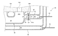
- FIG. 2A is a schematic cross-sectional view showing an example of the reduced diameter portion according to the present embodiment.
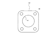
- FIG. 2B is a schematic plan view of the reduced diameter portion as viewed from the flow path axial direction.
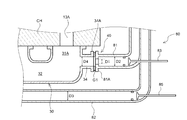
- FIG. 3 is a schematic cross-sectional view showing another example of the reduced diameter portion according to the present embodiment.
- FIG. 4 is a schematic cross-sectional view showing another example of the reduced diameter portion according to the present embodiment.
- FIG. 1 is a schematic overall configuration diagram showing an intake system and an exhaust system of an engine including the EGR device according to the present embodiment.
- the engine 10 mainly includes a cylinder block and an engine main body 11 including a cylinder head CH and the like provided on the upper part of the cylinder block.
- a plurality of cylinders C1 to C6 are provided in series in the longitudinal direction of the engine 10 in the cylinder block.
- the cylinder head CH is provided with a plurality of intake ports 12A to 12F for introducing intake air into the cylinders C1 to C6, and a plurality of exhaust ports 13A to 13F for deriving exhaust gas from the cylinders C1 to C6.
- the engine 10 is not limited to the in-line multi-cylinder engine shown in the illustrated example, and may be a V-type engine, a horizontally opposed engine, or the like. Further, the number of cylinders is not limited to the 6 cylinders in the illustrated example, and may be a single cylinder or a multi-cylinder other than the 6 cylinders. Further, the number of intake ports 12A to 12F and exhaust ports 13A to 13F is not limited to the structure of the illustrated example provided one for each cylinder C1 to C6, and is 2 for each cylinder C1 to C6. The structure may be provided individually.
- each cylinder C1 to C6 is referred to as the first cylinder C1, the second cylinder C2, the third cylinder C3, the fourth cylinder C4, the fifth cylinder C5, and the sixth cylinder C6 in order from the right side in the figure.
- the exhaust port 13A corresponding to the first cylinder C1 is the first exhaust port
- the exhaust port 13B corresponding to the second cylinder C2 is the second exhaust port
- the exhaust port 13C corresponding to the third cylinder C3 is the third.
- the exhaust port, the exhaust port 13D corresponding to the 4th cylinder C4 is the 4th exhaust port, the exhaust port 13E corresponding to the 5th cylinder C5 is the 5th exhaust port, and the exhaust port 13F corresponding to the 6th cylinder C6 is the 6th. It is called the exhaust port of.
- An intake manifold 20 that distributes intake air to the intake ports 12A to 12F is provided on the side portion of the cylinder head CH on the intake side.
- the air cleaner 21, the upstream intake pipe 22, the compressor housing 61 of the supercharger 60, the downstream intake pipe 23, and the like are connected to the intake manifold 20 in this order from the intake upstream side.
- the downstream intake pipe 23 is provided with an intercooler 24 for cooling the intake air pumped from the supercharger 60.
- the intercooler 24 may be either a water-cooled type or an air-cooled type.
- exhaust system The outlets of the exhaust ports 13A to 13F are arranged on the exhaust side of the cylinder head CH in the longitudinal direction of the engine 10.
- An exhaust manifold 30 is provided on the side of the cylinder head CH through which these outlets are opened.
- the upstream exhaust pipe 25, the turbine housing 62 of the supercharger 60, the downstream exhaust pipe 26, and the like are connected to the exhaust manifold 30 in this order from the exhaust upstream side.
- the downstream exhaust pipe 26 is provided with an exhaust aftertreatment device 70 and the like.
- the turbocharger 60 includes a compressor 63 housed in the compressor housing 61, a turbine 64 housed in the turbine housing 62, and a turbo shaft 65 connecting the compressor 63 and the turbine 64.
- the supercharger 60 is not limited to the conventional type shown in the illustrated example, and may be a variable capacitance type having variable wings.
- the exhaust manifold 30 includes a plurality of branch portions 31A to 31F, an exhaust collecting portion 32, an exhaust lead-out portion 33, a first EGR branch portion 34, and a second EGR branch portion 35.
- the branch portions 31A to 31F connect the outlet portions of the exhaust ports 13A to 13F and the exhaust collecting portion 32, respectively.
- the exhaust collecting portion 32 is provided so that its longitudinal direction is substantially parallel to the arrangement direction of the cylinders C1 to C6 (the arrangement direction of the outlet portions of the exhaust ports 13A to 13F), and flows from the branch portions 31A to 31F. Collect the exhaust gas.
- the exhaust lead-out unit 33 is connected to the upstream exhaust pipe 25 (when the upstream exhaust pipe 25 is omitted, the turbine housing 62), and the exhaust gas is led out from the exhaust collecting unit 32 toward the turbine 64.
- the exhaust lead-out portion 33 is provided at a substantially intermediate position (a portion corresponding to between the third exhaust port 13C and the fourth exhaust port 13D) of the exhaust collecting portion 32 in the longitudinal direction.
- the first EGR branch portion 34 is provided at the end portion 32A (the end portion on the right side in the drawing) adjacent to the first exhaust port 13A among the end portions 32A and 32B in the longitudinal direction of the exhaust collecting portion 32.
- the first EGR branch portion 34 is mainly discharged from the first exhaust port 13A, the second exhaust port 13B, and the third exhaust port 13C among the exhaust gases flowing into the exhaust collecting portion 32 from the respective exhaust ports 13A to 13F.
- the exhaust gas is introduced into the first EGR passage 81, which will be described later.
- the second EGR branching portion 35 is provided adjacent to the exhaust lead-out portion 33 at a substantially intermediate position in the longitudinal direction of the exhaust collecting portion 32.
- the second EGR branching portion 35 is mainly discharged from the fourth exhaust port 13D, the fifth exhaust port 13E, and the sixth exhaust port 13F among the exhaust gases flowing into the exhaust collecting portion 32 from the respective exhaust ports 13A to 13F.
- the exhaust gas is introduced into the second EGR passage 82, which will be described later.
- the exhaust gas discharged from the first to third exhaust ports 13A to 13C and the exhaust gas discharged from the fourth to sixth exhaust ports 13D to 13F are independently discharged to the exhaust collecting portion 32.
- a partition plate 36 for the purpose is provided.
- the EGR device 80 includes a first EGR passage 81 and a second EGR passage 82.
- the first EGR passage 81 and the second EGR passage 82 are examples of the recirculation passages of the present disclosure.
- the first EGR passage 81 connects the first EGR branch portion 34 and the intake manifold 20.
- the first EGR passage 81 is connected to the first EGR branch portion 34 with a gasket G1 interposed therebetween.
- the gasket G1 seals the gap between the first EGR branch portion 34 and the first EGR passage 81.
- the second EGR passage 82 connects the second EGR branch portion 35 and the intake manifold 20.
- the second EGR passage 82 is connected to the second EGR branch portion 35, preferably with a gasket G2 interposed therebetween.
- the gasket G2 seals the gap between the second EGR branch portion 35 and the second EGR passage 82.
- first EGR passage 81 and the second EGR passage 82 are connected to the intake manifold 20, but they may be connected to the downstream intake pipe 23. Further, the first EGR passage 81 and the second EGR passage 82 can be connected to the upstream intake pipe 22 on the upstream side of the compressor 63.
- the first EGR passage 81 is provided with a first EGR valve 83 and a first EGR cooler 84 in this order from the upstream side in the flow direction of the EGR gas.
- the second EGR passage 82 is provided with a second EGR valve 85 and a second EGR cooler 86 in this order from the upstream side in the flow direction of the EGR gas.
- each EGR valve 83, 85 is controlled by transmitting an instruction signal from a control device (not shown) to the actuators 83A, 85A according to a target EGR rate or the like set based on the operating state of the engine 10. Will be done.
- the operating state of the engine 10 may be acquired by an engine speed sensor, an accelerator opening sensor, or the like (not shown).
- the EGR coolers 84 and 86 may be either water-cooled or air-cooled.
- the first EGR passage 81 extends in the longitudinal direction of the engine 10 from the first EGR branch portion 34 provided at the longitudinal end 32A of the exhaust collecting portion 32, and is on the intake side in front of the cylinder head CH. After being bent to extend the front side of the cylinder head CH in the lateral direction of the engine 10, the outside of the intake manifold 20 is extended and connected to a predetermined portion of the intake manifold 20.
- the first EGR valve 83 is preferably provided at a portion where the first EGR passage 81 is bent toward the intake side on the front side of the cylinder head CH.
- the second EGR passage 82 extends the outside of the exhaust manifold 30 in the longitudinal direction of the engine 10 from the second EGR branch portion 35 provided at a substantially intermediate position in the longitudinal direction of the exhaust collecting portion 32, and is more than the cylinder head CH.
- a predetermined portion of the intake manifold 20 (preferably, the first EGR passage). It is connected to (almost the same part as 81).
- the second EGR valve 85 is preferably provided adjacent to the first EGR valve 83 at a portion where the second EGR passage 81 is bent toward the intake side on the front side of the cylinder head CH.
- the first EGR passage 81 and the second EGR passage 82 are provided adjacent to each other substantially parallel to each other from the portions downstream of the EGR valves 83 and 85, so that two systems of EGR passages 81 and 82 are provided. Also, the EGR device 80 as a whole can be made compact.
- the first EGR passage 81 and the second EGR passage 82 configured as described above are the second EGR of the second EGR passage 82 with respect to the length L1 from the first EGR branch portion 34 to the first EGR valve 83 of the first EGR passage 81.
- the length L2 from the branch portion 35 to the second EGR valve 85 is at least the amount of the separation length L3 between the first EGR branch portion 34 and the second EGR branch portion 35 (about half the length in the longitudinal direction of the exhaust collecting portion 32). It is formed to be long. That is, the flow path of the second EGR passage 82 is formed to be longer than the flow path of the first EGR passage 81 by at least the separation length L3 between the first EGR branch portion 34 and the second EGR branch portion 35. ..
- the flow rate from the fourth to sixth exhaust ports 13D to 13F is relative to the flow rate of the EGR gas introduced from the first to third exhaust ports 13A to 13C into the first EGR passage 81 having a short flow path.
- the flow rate of the EGR gas introduced into the long second EGR passage 82 tends to decrease, and a difference in the flow rate of the EGR gas flowing through the EGR passages 81 and 82 is generated.
- the first EGR passage 81 having a short flow path is provided with a reduced diameter portion 40 for reducing the amount of EGR gas flowing through the first EGR passage 81.
- the reduced diameter portion 40 is preferably provided in the first EGR passage 81 on the upstream side of the first EGR valve 83, and the amount of EGR gas can be adjusted to a desired flow rate without being significantly affected by the change in the opening degree of the first EGR valve 83. It is configured so that it can be effectively reduced.
- a more detailed configuration of the reduced diameter portion 40 according to the present embodiment will be described.
- FIG. 2A is a schematic cross-sectional view showing an example of the reduced diameter portion 40 according to the present embodiment
- FIG. 2B is a schematic plan view of the reduced diameter portion 40 viewed from the flow path axial direction.
- the reduced diameter portion 40 is provided between the outlet flange portion 34A formed in the first EGR branch portion 34 and the inlet flange portion 81A formed in the first EGR passage 81. It is composed of a gasket G1.
- the gasket G1 is formed in a rectangular plate shape or a circular plate shape having substantially the same shape as the outer peripheral shape of each of the flange portions 34A and 81A, and a through hole for passing EGR gas is formed in the substantially central portion thereof. 41 is provided.
- the reduced diameter portion 40 forms the hole diameter D1 of the through hole 41 of the gasket G1 to be smaller than the flow path diameter D2 of the first EGR passage 81, the flow path diameter D3 of the second EGR passage 82, and the flow path diameter D4 of the first EGR branch portion 34. It is composed of.
- the value of the hole diameter D1 depends on the specific specifications such as the displacement of the engine 10, the number of cylinders, the flow path diameters D2 and D3 of the EGR passages 81 and 82, and the like, and flows through the EGR passages 81 and 82.
- the difference in the flow rate of the EGR gas is reduced, and preferably, the EGR gas flow rate in the EGR passages 81 and 82 may be appropriately set so as to be substantially equal.
- the exhaust manifold 30 and the EGR passages 81 and 82 are not required to be redesigned, and the structure is simple.
- the difference in the flow rate of the EGR gas flowing through the EGR passages 81 and 82 can be effectively and easily reduced.
- the flow path diameter D2 of the first EGR passage 81 and the flow path diameter D3 of the second EGR passage 82 are shown to be substantially the same diameter, but in the present disclosure, these flow path diameters D2 and D3 are different diameters. Does not preclude being formed by.
- FIG. 3 is a schematic cross-sectional view showing another example of the reduced diameter portion 40 according to the present embodiment.
- the reduced diameter portion 40 uses the flow path diameter D1 of the inlet flange portion 81A formed in the first EGR passage 81 as the flow path diameter D2 of the first EGR passage 81 and the flow path diameters D3 of the second EGR passage 82. 1
- the EGR branch portion 34 is formed to have a diameter smaller than the flow path diameter D4.
- the configuration of the reduced diameter portion 40 is not limited to the examples of FIGS. 2A, 2B, and 3, and for example, as shown in FIG. 4, a predetermined portion of the first EGR passage 81 on the upstream side of the first EGR valve 83 has a diameter. It may be formed by denting inward in the direction. Alternatively, although detailed illustration is omitted, it can also be formed by a gasket or the like interposed at the joint between the pipes, such as the joint between the first EGR passage 81 and the valve housing of the first EGR valve 83.
- the EGR device 80 includes two systems of EGR passages 81 and 82 having different lengths, and the first EGR passage 81 having a shorter flow path than the second EGR passage 82 A reduced diameter portion 40 is provided to partially reduce the flow path diameter of the first EGR passage 81. That is, by providing the reduced diameter portion 40 for reducing the flow path diameter in the short first EGR passage 81 through which the EGR gas easily flows, the flow rate of the EGR gas flowing through the first EGR passage 81 can be effectively reduced. ing.
- the flow rate difference between the EGR gas flowing through the first EGR passage 81 having a short flow path and the EGR gas flowing through the second EGR passage 82 having a long flow path can be effectively reduced, or the flow rates of these EGR gases can be equalized. It becomes possible to plan.
- the drive of the turbocharger 60 can be stabilized, and the intake air is efficiently pumped to each cylinder C1 to C6 (in other words, the intake amount of each cylinder C1 to C6 is insufficient. Can be effectively prevented), and the accuracy of engine control can be improved.
- the accuracy of engine control it is possible to improve fuel efficiency and exhaust emission performance.
- the reduced diameter portion 40 has been described as being provided on the upstream side of the first EGR valve 83, but the flow path length of the first EGR passage 81, the positional relationship between the first EGR valve 83 and the first EGR cooler 84, etc. Accordingly, the reduced diameter portion 40 can be provided on the downstream side of the first EGR valve 81 (for example, between the EGR valve 83 and the EGR cooler 84).
- the positional relationship between the first EGR branching portion 34 and the second EGR branching portion 35 is not limited to the illustrated example, and if the positional relationship is such that the EGR passages 81 and 82 connected to them have different flow path lengths, for example. It is also possible to make various modifications such as providing the second EGR branching portion 35 at the end portion 32B adjacent to the sixth exhaust port 13F of the exhaust collecting portion 32.
- the EGR passages 81 and 82 have been described as branching from the exhaust manifold 30, they may be configured to branch from the upstream exhaust pipe 25 on the downstream side of the exhaust manifold 30. In that case, the exhaust is discharged from the first to third exhaust ports 13A to 13C on the condition that the same effective area as before the partition plate is provided on the upstream exhaust pipe 25 (the state where the partition plate is not provided) is secured. It is desirable that the upstream exhaust pipe 25 is provided with a partition plate for independently discharging the exhaust gas and the exhaust gas discharged from the fourth to sixth exhaust ports 13D to 13F.
- the EGR device 80 has been described as having two EGR passages 81 and 82, it may be configured to include three or more EGR passages. In this case, except for the EGR passage having the longest flow path, a reduced diameter portion 40 is provided for each of the remaining EGR passages shorter than the EGR passage, and the flow path has the flow path diameters of the plurality of reduced diameter portions 40. It may be formed so that the shorter the EGR passage is, the smaller the diameter is.
- the exhaust gas recirculation device including a plurality of EGR passages having different flow path lengths according to the present disclosure is useful in that it can effectively reduce the flow rate difference of the EGR gas flowing through each EGR passage. ..
Landscapes
- Engineering & Computer Science (AREA)
- Chemical & Material Sciences (AREA)
- Combustion & Propulsion (AREA)
- Mechanical Engineering (AREA)
- General Engineering & Computer Science (AREA)
- Exhaust-Gas Circulating Devices (AREA)
Abstract
L'invention concerne un dispositif de recirculation des gaz d'échappement 80 comprenant une pluralité de systèmes de canaux de recirculation 81 et 82 qui se ramifient à partir d'un système d'échappement d'un moteur 10 et fusionnent avec un système d'admission du moteur 10, ce qui permet de faire recirculer au moins une partie des gaz d'échappement vers le système d'admission, où, parmi la pluralité de systèmes de canaux de recirculation 81 et 82, au moins deux systèmes de canaux de recirculation 81 et 82 sont formés avec des longueurs de canal qui diffèrent l'une de l'autre et, parmi les canaux de recirculation 81 et 82 avec différentes longueurs de canal, au niveau d'une partie prédéterminée du canal de recirculation plus court 81, une partie à diamètre réduit 40 réduit le diamètre de canal du canal de recirculation plus court 81.
Applications Claiming Priority (2)
| Application Number | Priority Date | Filing Date | Title |
|---|---|---|---|
| JP2019-180503 | 2019-09-30 | ||
| JP2019180503A JP2021055635A (ja) | 2019-09-30 | 2019-09-30 | 排気再循装置 |
Publications (1)
| Publication Number | Publication Date |
|---|---|
| WO2021065723A1 true WO2021065723A1 (fr) | 2021-04-08 |
Family
ID=75272385
Family Applications (1)
| Application Number | Title | Priority Date | Filing Date |
|---|---|---|---|
| PCT/JP2020/036290 Ceased WO2021065723A1 (fr) | 2019-09-30 | 2020-09-25 | Dispositif de recirculation de gaz d'échappement |
Country Status (2)
| Country | Link |
|---|---|
| JP (1) | JP2021055635A (fr) |
| WO (1) | WO2021065723A1 (fr) |
Citations (9)
| Publication number | Priority date | Publication date | Assignee | Title |
|---|---|---|---|---|
| JPS54155018U (fr) * | 1978-04-18 | 1979-10-27 | ||
| JPH07208273A (ja) * | 1994-01-20 | 1995-08-08 | Toyota Motor Corp | 負圧駆動アクチュエータの制御装置 |
| JPH09264202A (ja) * | 1996-03-29 | 1997-10-07 | Nissan Diesel Motor Co Ltd | 慣性過給付エンジンの排気還流装置 |
| JPH11210560A (ja) * | 1998-01-20 | 1999-08-03 | Nissan Motor Co Ltd | エンジンの排気ガス還流装置 |
| JP2000045878A (ja) * | 1998-07-27 | 2000-02-15 | Mazda Motor Corp | エンジンの排気還流装置 |
| JP2000064912A (ja) * | 1998-08-24 | 2000-03-03 | Isuzu Motors Ltd | Egr装置 |
| US20060021328A1 (en) * | 2004-07-29 | 2006-02-02 | Johannes Leweux | Exhaust gas recirculation device for an internal combustion engine |
| JP2006329051A (ja) * | 2005-05-26 | 2006-12-07 | Hino Motors Ltd | 車両用エンジンのegr装置 |
| JP2016044584A (ja) * | 2014-08-21 | 2016-04-04 | いすゞ自動車株式会社 | 排気再循環装置 |
-
2019
- 2019-09-30 JP JP2019180503A patent/JP2021055635A/ja active Pending
-
2020
- 2020-09-25 WO PCT/JP2020/036290 patent/WO2021065723A1/fr not_active Ceased
Patent Citations (9)
| Publication number | Priority date | Publication date | Assignee | Title |
|---|---|---|---|---|
| JPS54155018U (fr) * | 1978-04-18 | 1979-10-27 | ||
| JPH07208273A (ja) * | 1994-01-20 | 1995-08-08 | Toyota Motor Corp | 負圧駆動アクチュエータの制御装置 |
| JPH09264202A (ja) * | 1996-03-29 | 1997-10-07 | Nissan Diesel Motor Co Ltd | 慣性過給付エンジンの排気還流装置 |
| JPH11210560A (ja) * | 1998-01-20 | 1999-08-03 | Nissan Motor Co Ltd | エンジンの排気ガス還流装置 |
| JP2000045878A (ja) * | 1998-07-27 | 2000-02-15 | Mazda Motor Corp | エンジンの排気還流装置 |
| JP2000064912A (ja) * | 1998-08-24 | 2000-03-03 | Isuzu Motors Ltd | Egr装置 |
| US20060021328A1 (en) * | 2004-07-29 | 2006-02-02 | Johannes Leweux | Exhaust gas recirculation device for an internal combustion engine |
| JP2006329051A (ja) * | 2005-05-26 | 2006-12-07 | Hino Motors Ltd | 車両用エンジンのegr装置 |
| JP2016044584A (ja) * | 2014-08-21 | 2016-04-04 | いすゞ自動車株式会社 | 排気再循環装置 |
Also Published As
| Publication number | Publication date |
|---|---|
| JP2021055635A (ja) | 2021-04-08 |
Similar Documents
| Publication | Publication Date | Title |
|---|---|---|
| US7581533B1 (en) | Three mode cooler for exhaust gas recirculation | |
| JP4496248B2 (ja) | Egr装置付き過給エンジン | |
| US8935917B2 (en) | Partially integrated exhaust manifold | |
| US7311090B2 (en) | Engine exhaust gas passage flow orifice and method | |
| JP2004092646A (ja) | 内燃機関用過給装置 | |
| CN204572261U (zh) | 排气再循环冷却器和排气再循环系统 | |
| JP6026825B2 (ja) | 内燃機関の吸気装置 | |
| CN102498275B (zh) | 带增压器的内燃机 | |
| WO2013172129A1 (fr) | Dispositif de décharge de gaz d'échappement pour moteur à combustion interne | |
| JPS63309724A (ja) | 過給機付多気筒エンジンの排気装置 | |
| WO2021065723A1 (fr) | Dispositif de recirculation de gaz d'échappement | |
| JP2007231906A (ja) | 多気筒エンジン | |
| JP5168268B2 (ja) | 内燃機関の排気還流装置 | |
| US11359583B2 (en) | EGR device | |
| JP2007285169A (ja) | 過給機付き内燃機関のシリンダヘッド構造 | |
| JPH0523823Y2 (fr) | ||
| CN110735711A (zh) | 八缸发动机的排气系统、排气方法及车辆 | |
| JPS6155355A (ja) | 多気筒エンジンの排気ガス還流装置 | |
| JPH04237826A (ja) | 過給機付内燃機関 | |
| JP2021080911A (ja) | エンジン | |
| US20260055749A1 (en) | Pulse capture assembly and an engine system | |
| JP7296272B2 (ja) | 内燃機関 | |
| JP5447094B2 (ja) | 内燃機関の排気還流装置 | |
| JP2005351220A (ja) | 内燃機関の吸気装置 | |
| GB2504829A (en) | Flow connector for a Boosted Internal Combustion Engine |
Legal Events
| Date | Code | Title | Description |
|---|---|---|---|
| 121 | Ep: the epo has been informed by wipo that ep was designated in this application |
Ref document number: 20872321 Country of ref document: EP Kind code of ref document: A1 |
|
| NENP | Non-entry into the national phase |
Ref country code: DE |
|
| 122 | Ep: pct application non-entry in european phase |
Ref document number: 20872321 Country of ref document: EP Kind code of ref document: A1 |