WO2021075301A1 - Dispositif de détection d'ouverture/de fermeture de porte et dispositif d'ouverture/de fermeture de porte - Google Patents
Dispositif de détection d'ouverture/de fermeture de porte et dispositif d'ouverture/de fermeture de porte Download PDFInfo
- Publication number
- WO2021075301A1 WO2021075301A1 PCT/JP2020/037771 JP2020037771W WO2021075301A1 WO 2021075301 A1 WO2021075301 A1 WO 2021075301A1 JP 2020037771 W JP2020037771 W JP 2020037771W WO 2021075301 A1 WO2021075301 A1 WO 2021075301A1
- Authority
- WO
- WIPO (PCT)
- Prior art keywords
- handle
- door
- sub
- open
- switch
- Prior art date
- Legal status (The legal status is an assumption and is not a legal conclusion. Google has not performed a legal analysis and makes no representation as to the accuracy of the status listed.)
- Ceased
Links
Images




Classifications
-
- E—FIXED CONSTRUCTIONS
- E05—LOCKS; KEYS; WINDOW OR DOOR FITTINGS; SAFES
- E05B—LOCKS; ACCESSORIES THEREFOR; HANDCUFFS
- E05B85/00—Details of vehicle locks not provided for in groups E05B77/00 - E05B83/00
- E05B85/10—Handles
- E05B85/12—Inner door handles
-
- B—PERFORMING OPERATIONS; TRANSPORTING
- B60—VEHICLES IN GENERAL
- B60J—WINDOWS, WINDSCREENS, NON-FIXED ROOFS, DOORS, OR SIMILAR DEVICES FOR VEHICLES; REMOVABLE EXTERNAL PROTECTIVE COVERINGS SPECIALLY ADAPTED FOR VEHICLES
- B60J5/00—Doors
- B60J5/04—Doors arranged at the vehicle sides
- B60J5/047—Doors arranged at the vehicle sides characterised by the opening or closing movement
- B60J5/0473—Doors arranged at the vehicle sides characterised by the opening or closing movement the door having a hinge axis in the direction of the vehicle longitudinal axis
-
- E—FIXED CONSTRUCTIONS
- E05—LOCKS; KEYS; WINDOW OR DOOR FITTINGS; SAFES
- E05B—LOCKS; ACCESSORIES THEREFOR; HANDCUFFS
- E05B81/00—Power-actuated vehicle locks
- E05B81/54—Electrical circuits
- E05B81/64—Monitoring or sensing, e.g. by using switches or sensors
- E05B81/76—Detection of handle operation; Detection of a user approaching a handle; Electrical switching actions performed by door handles
-
- E—FIXED CONSTRUCTIONS
- E05—LOCKS; KEYS; WINDOW OR DOOR FITTINGS; SAFES
- E05F—DEVICES FOR MOVING WINGS INTO OPEN OR CLOSED POSITION; CHECKS FOR WINGS; WING FITTINGS NOT OTHERWISE PROVIDED FOR, CONCERNED WITH THE FUNCTIONING OF THE WING
- E05F15/00—Power-operated mechanisms for wings
- E05F15/60—Power-operated mechanisms for wings using electrical actuators
- E05F15/603—Power-operated mechanisms for wings using electrical actuators using rotary electromotors
- E05F15/611—Power-operated mechanisms for wings using electrical actuators using rotary electromotors for swinging wings
Definitions
- the present invention relates to a door open / close detection device and a door open / close device.
- the vehicle door opening / closing device described in Patent Document 1 below can automatically open / close the vehicle door.
- an inner door opening / closing switch is provided on the armrest of the door, and when the occupant sets the inner door switch to OPEN or CLOSE, the inner door switch detection unit can be used as the inner door switch. Detect the operation. Then, when the inner door switch detection unit detects the operation of the inner door switch, the door opening / closing drive unit is driven to open / close the door.
- the inner door switch is configured as a so-called seesaw type switch.
- the occupant can rotate the door in the opening direction by pulling the door inner handle toward the vehicle interior side. That is, in the vehicle door opening / closing device, the operation of the inner door switch is different from the operation of the conventional manual door inner handle. Therefore, the occupant cannot intuitively recognize the operation of the inner door switch, which may reduce the operability.
- An object of the present invention is to provide a door open / close detection device and a door open / close device capable of improving operability in consideration of the above facts.
- a base attached to a vehicle door and one end side portion are rotatably supported by the base with the vertical direction as an axial direction, and the door is rotatably supported on the vehicle interior side.
- the grip portion that is operably exposed is provided at the other end, and when the grip portion is operated, the grip portion is rotated from the neutral position to the closing direction of the door, or from the pulling operation position or the neutral position to the opening direction of the door.
- a door open / close detection device including a handle that is rotated to a rotated push operation position, and a detection unit that detects a push operation position and a pull operation position of the handle.
- the detection unit is a door open / close detection device which is a switch operated by the handle at the push operation position and the pull operation position.
- the detection unit has a pair of the switches, and the handle has one end rotatably pivotally supported by the base and the other end.
- the handle body having the grip portion and the handle body are pivotally supported on the base coaxially with the handle body, and interlock with the handle body when rotating from the neutral position of the handle body to one side in the rotation direction.
- the handle body has a body-side operation unit that operates one of the pair of switches when rotating from a neutral position to the other side in the rotation direction
- the sub-handle is a handle body of the handle body. It is a door open / close detection device having a sub-side operation unit that operates the other of the pair of the switches when rotating from the neutral position to one side in the rotation direction.
- a first urging member that urges the handle body to one side in the rotation direction with respect to the sub handle and the sub handle in the rotation direction with respect to the base.
- a second urging member for urging the other side is provided, and in a neutral position, the sub-handle abuts on the base to limit the rotation of the sub-handle to the other side in the rotation direction, and the above-mentioned
- This is a door open / close detection device in which the handle body abuts on the sub handle and the rotation of the handle body in one side in the rotation direction is restricted.
- the handle is provided with a magnet
- the detection unit has a pair of magnetic sensors, and when the handle is rotated, one of the magnetic sensors is used.
- the pulling operation position of the handle is detected by detecting the approach of the magnet
- the pushing operation position of the handle is detected by detecting the approach of the magnet by the other magnetic sensor when the handle is rotated. It is a door open / close detection device.
- One or more embodiments of the present invention include the door open / close detection device of the above embodiment, a door open / close drive unit that drives the door of the vehicle to open / close, a door open / close position detection unit that detects the open / close position of the door, and the above.
- a control unit that controls a door opening / closing drive unit is provided, and when the handle is rotated to a pulling operation position while the door is arranged in a fully closed position, the control unit causes the door opening / closing drive unit. Is a door opening / closing device that drives the door to rotate the door in the opening direction.
- the control unit when the handle is rotated to the push operation position while the door is arranged in the fully closed position, the control unit is the door opening / closing drive unit. It is a door opening / closing device that prohibits driving.
- the control unit drives the door to open / close. It is a door opening / closing device that drives a unit to rotate the door in the closing direction.
- the control unit drives the door opening / closing drive unit. It is a door opening / closing device that rotates the door in the opening direction.
- operability can be improved.
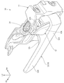
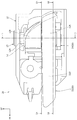
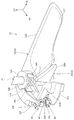
- FIG. 2 It is a side view seen from the right side which shows the vehicle which mounted the door opening / closing device which concerns on this embodiment. It is a perspective view which shows the door opening / closing detection device which concerns on this embodiment. It is a side view seen from the left side which shows the door open / close detection device shown in FIG. It is an exploded perspective view which shows the door open / close detection apparatus shown in FIG. 2 in the disassembled state. It is sectional drawing (5-5 line sectional drawing of FIG. 3) seen from the rear side which shows the rear part of the door open / close detection apparatus shown in FIG. (A) is a cross-sectional view (cross-sectional view taken along the line 6A-6A of FIG.
- FIG. 3 shows an intermediate portion in the vertical direction of the door open / close detection device shown in FIG. 3, and (B) is shown in FIG. It is sectional drawing (6B-6B line sectional drawing of FIG. 3) seen from the upper side which shows the lower part of the door open / close detection apparatus.
- A) is a perspective view of the handle body shown in FIG. 4 as viewed from the right side
- B) is a perspective view of the sub handle shown in FIG. 4 as viewed from the right side.
- A) is a cross-sectional view corresponding to FIG. 6 (A) when the handle body of FIG.
- FIG. 6 (A) is pushed to the push operation position
- (B) is a cross-sectional view of the handle body of FIG. 6 (B). It is sectional drawing corresponding to FIG. 6 (B) at the time of pulling operation to a pulling operation position.
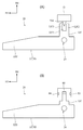
- (A) is a plan view seen from the upper side schematically showing a modification of the door open / close detection device shown in FIG. 2, and (B) schematically shows another modification of the door open / close detection device. It is a plan view seen from the upper side.
- the door opening / closing device 10 As shown in FIG. 1, the door opening / closing device 10 is mounted on the vehicle V (automobile).
- the arrow UP, the arrow FR, and the arrow RH which are appropriately shown, indicate the upper side of the vehicle V, the front side of the vehicle, and the right side of the vehicle (one side in the vehicle width direction), respectively.
- the vehicle up / down direction, the vehicle front / rear direction, and the vehicle left / right direction are indicated unless otherwise specified.
- the door opening / closing device 10 is configured as a device that automatically opens / closes the door D (side door) of the vehicle V.
- the door opening / closing device 10 includes a door opening / closing detection device 20, a door opening / closing drive unit 60, a door opening / closing position detecting device 62 as a "door opening / closing position detecting unit", and a control unit 64.
- the door open / close detection device 20 is mounted on the door D.
- the door open / close detection device 20 will be described as an example in which the door open / close detection device 20 is mounted on the door D on the right front side of the vehicle V.
- the front end portion of the door D is connected to the front pillar of the vehicle V so as to be openable and closable by a door hinge (not shown) with the vertical direction as the axial direction.
- the door D has a fully closed position that closes the door opening of the vehicle V and a fully open position that is rotated to the right side (outside in the vehicle width direction) from the fully closed position to open the door opening.
- the space can be opened and closed.
- each configuration of the door opening / closing device 10 will be described.
- the door open / close detection device 20 includes a base 22, a handle 30, a first urging spring 40 as a “first urging member”, and a “second urging member”.
- a second urging spring 42 as a "detection unit” and a first switch 44 as a “detection unit” and a “switch”, a second switch 46 as a "detection unit” and a “switch”, and a knob cover 52.
- the door D will be described as being arranged in the fully closed position.
- the base 22 is formed in a substantially rectangular box shape open to the left side (vehicle interior side) and the front side, and is fixed to the inner panel (not shown) of the door D. ..
- a support shaft 24 is bridged between the upper wall and the lower wall at the rear portion of the base 22, and the support shaft 24 is formed in a substantially columnar shape with the vertical direction as the axial direction.
- a support piece 22A projecting to the left side is integrally formed on the bottom wall (right wall) of the base 22, and the axial intermediate portion of the support shaft 24 is also supported by the support piece 22A.
- an opening 22B for arranging the first switch 44 and the second switch 46, which will be described later, is formed through the bottom wall at the rear portion of the base 22.
- a substantially cylindrical base stopper portion 22C protruding to the left side is formed at the front side edge portion of the opening 22B.
- a recess opened to the left is formed on the left end surface of the base stopper portion 22C, and a mounting hole 22C1 is formed through the bottom surface of the recess.
- a first cushion 26 (see FIG. 6B) is attached to the recess of the base stopper portion 22C.
- the first cushion 26 is made of an elastic material such as rubber, and is formed in a substantially shaft shape with the left-right direction as the axial direction.
- the first cushion 26 is inserted into the mounting hole 22C1 from the left side, the left end portion of the first cushion 26 is fitted into the recess of the base stopper portion 22C, and the first cushion 26 is fixed to the base stopper portion 22C. ing. Further, in the fixed state of the first cushion 26, the left end surface of the first cushion 26 slightly protrudes to the left side of the base stopper portion 22C.
- the handle 30 includes a handle main body 32 and a sub handle 34.
- the handle body 32 is formed in a substantially rectangular parallelepiped block shape extending in the front-rear direction, and in a plan view seen from the upper side, the left side becomes larger toward the front side. It is arranged at a slight inclination.
- the rear end side portion (one end side portion) of the handle body 32 is configured as the handle mounting portion 32A, and the handle mounting portion 32A is formed in a concave shape that is open to the right side.
- a substantially bottomed cylindrical main body side shaft portion 32B that is raised upward and is open to the right side and the lower side is formed, and the main body side shaft portion 32B is a handle mounting portion.
- a pair of upper and lower main body side support holes 32C are formed through the top wall of the main body side shaft portion 32B and the lower wall of the handle mounting portion 32A, and the pair of main body side support holes 32C are arranged coaxially.
- the handle mounting portion 32A is arranged between the lower wall of the base 22 and the support piece 22A, and the lower portion of the support shaft 24 is inserted into the main body side support hole 32C.
- the handle body 32 is rotatably supported on the base 22 via the support shaft 24 with the vertical direction as the axial direction.
- the front end (the other end) of the handle body 32 is configured as a grip portion 32D.
- the grip portion 32D is formed with a hollow portion 32E that is open to the upper side and the right side (outside in the vehicle width direction). Further, the front end side portion of the grip portion 32D is cut out so as to be open to the front side and the right side in a plan view.
- the steering wheel body 32 is exposed so as to be rotatable from the door trim (interior member) of the door D to the vehicle interior side (left side).
- the occupant grips the grip portion 32D of the handle body 32 and rotates the handle body 32, so that the handle body 32 rotates around the support shaft 24.
- the grip portion 32D of the handle body 32 is on one side in the rotation direction (inside the vehicle interior) from the neutral position shown in FIGS. 6A and 6B, and is on the side in the direction in which the door D is closed (FIG. 6).
- the pulling operation position rotated to (the arrow B direction side of (B))) or the other side in the rotation direction from the neutral position (outside the passenger compartment, door D).
- a switch operating portion 32F as a "main body side operating portion" extending to the right side is formed on the upper wall of the handle mounting portion 32A.
- the tip of the switch operation unit 32F is configured as a portion for operating the first switch 44, which will be described later.
- a main body side contact portion 32G is formed in the lower right portion.
- the main body side contact portion 32G is configured as a surface along a direction orthogonal to the left-right direction.
- the sub handle 34 has a substantially columnar sub-side shaft portion 34A whose axial direction is the vertical direction.
- a first accommodating portion 34B opened to the left is formed in the lower part of the sub-side shaft portion 34A
- a second accommodating portion 34C opened to the right is formed in the upper part of the sub-side shaft portion 34A.
- Sub-side support holes 34D are formed through the upper wall, lower wall, and intermediate wall (wall portion between the first accommodating portion 34B and the second accommodating portion 34C) of the sub-side shaft portion 34A, respectively.
- the portion excluding the lower wall of the sub-side shaft portion 34A is inserted into the handle mounting portion 32A of the handle body 32, and the support shaft 24 is inserted into the sub-side support hole 34D (see FIG. 5). ).
- the sub handle 34 is rotatably supported on the base 22 via the support shaft 24. That is, the sub-handle 34 is rotatably supported on the base 22 coaxially with the handle body 32.
- the lower wall of the sub side shaft portion 34A is arranged between the lower wall of the base 22 and the handle main body 32.
- the sub-handle 34 has a mounted portion 34E extending rearward from the sub-side shaft portion 34A, and the mounted portion 34E is inserted into the handle mounting portion 32A of the handle main body 32. ..
- a sub-stopper portion 34F (see FIGS. 4, 6 (B), and 7 (B)) projecting to the rear side is formed at the rear end portion of the attached portion 34E, and the sub-stopper portion 34F is formed. It is formed in a plate shape with the left and right directions as the plate thickness direction.
- the sub-stopper portion 34F is arranged adjacent to the right side of the main body-side contact portion 32G in the handle main body 32, and the main body-side contact portion 32G is brought to the sub-stopper portion 34F by the urging force of the first urging spring 40 described later. They are in contact (see FIG. 6B).
- a recess opened to the left is formed on the left end surface of the sub-stopper portion 34F, and a mounting hole 34G is formed through the bottom surface of the recess.
- a second cushion 36 (see FIGS. 4 and 6B) is attached to the recess of the sub-stopper portion 34F.
- the second cushion 36 is made of an elastic material such as rubber, and is formed in a substantially shaft shape with the left-right direction as the axial direction. Then, the left end portion of the second cushion 36 is fitted into the mounting hole 34G, and the second cushion 36 is fixed to the sub stopper portion 34F in a state of extending from the sub stopper portion 34F to the right side. Further, in the fixed state of the second cushion 36, the left end surface of the second cushion 36 slightly protrudes to the left side of the sub-stopper portion 34F.
- the sub-handle 34 has a sub-side contact portion 34H extending forward from the sub-side shaft portion 34A.
- the sub-side contact portion 34H is formed in a substantially triangular plate shape with the left-right direction as the plate thickness direction.
- the sub-side contact portion 34H is arranged between the rear end portion of the grip portion 32D in the handle body 32 and the base stopper portion 22C of the base 22.
- the sub-side contact portion 34H abuts on the base stopper portion 22C and is arranged with a predetermined gap on the right side with respect to the rear end portion of the grip portion 32D (FIG. 6 (A)).
- FIG. 6 (A) the rotation of the sub handle 34 on the other side in the rotation direction
- the side in the direction of arrow A in FIG. 6A is restricted by the base 22.
- the sub handle 34 has a cam piece 34J extending to the right from the sub side shaft portion 34A.
- the cam piece 34J is formed in a substantially plate shape with the vertical direction as the plate thickness direction.
- a cam portion 34K as a "sub-side operation portion" protruding upward is integrally formed.
- the cam portion 34K is formed in a substantially fan shape centered on the central axis of the sub-side support hole 34D in a plan view, and the tip portion of the cam portion 34K is configured as a cam surface 34L.
- a notch portion 34M opened to the right side and the upper side is formed in the intermediate portion in the longitudinal direction of the cam surface 34L.
- the first urging spring 40 is composed of a torsion spring.
- the first urging spring 40 is housed in the first housing portion 34B of the sub handle 34 and is extrapolated to the support shaft 24.
- One end of the first urging spring 40 is locked to the sub-side contact portion 34H of the sub handle 34, and the other end of the first urging spring 40 is locked to the handle mounting portion 32A of the handle body 32.
- the first urging spring 40 urges the handle body 32 with respect to the sub handle 34 toward the pulling operation position side (one side in the rotation direction).
- the main body side contact portion 32G of the handle main body 32 comes into contact with the sub stopper portion 34F of the sub handle 34, and the second cushion 36 is compressed and deformed by the main body side contact portion 32G.
- the second urging spring 42 is composed of a torsion spring like the first urging spring 40.
- the second urging spring 42 is housed in the second housing portion 34C of the sub handle 34 and is extrapolated to the support shaft 24.
- One end of the second urging spring 42 is locked to the base 22, and the other end of the second urging spring 42 is locked to the attached portion 34E of the sub handle 34. 42 pushes the sub handle 34 and urges it to the operation position side (the other side in the rotation direction).
- the sub-side contact portion 34H of the sub-handle 34 comes into contact with the base stopper portion 22C of the base 22, and the first cushion 26 is compressed and deformed.
- the state in which the sub-side contact portion 34H is in contact with the base stopper portion 22C is the neutral position of the sub handle 34, and the sub handle 34 is held in the neutral position by the urging force of the second urging spring 42. ing. Further, in the neutral position of the sub handle 34, the handle body 32 is held in the neutral position by the urging force of the first urging spring 40.
- the handle body 32 when the handle body 32 is rotated from the neutral position to the pulling operation position side, the body-side contact portion 32G of the handle body 32 presses the sub-stopper portion 34F of the sub-handle 34 to the right, and the handle body 32
- the sub-handle 34 is configured to rotate toward the pulling operation position side against the urging force of the second urging spring 42. That is, when the handle body 32 is rotated from the neutral position to the pulling operation position side, the sub handle 34 rotates in conjunction with the rotation of the handle body 32, and the sub-side contact portion 34H of the sub handle 34 It is configured to be separated from the base stopper portion 22C of the base 22 to the left side.
- the handle body 32 when the handle body 32 is rotated from the neutral position to the push operation position side, the rotation of the sub handle 34 to the push operation position side is restricted by the base 22, so that only the handle body 32 is pushed. It is configured to rotate to the position side. That is, the state of being arranged in the neutral position of the sub handle 34 is maintained, and the main body side contact portion 32G of the handle main body 32 is separated from the sub stopper portion 34F of the sub handle 34 to the left side.
- the handle body 32 returns to the neutral position by the urging force of the first urging spring 40.
- the first switch 44 and the second switch 46 are configured as lever-type switches and are electrically connected to a control unit 64 described later.
- the first switch 44 is arranged close to the lower side of the tip end portion of the switch operation portion 32F in the handle body 32. Further, in the first switch 44, the first switch 44 is arranged so that the axial direction of the rotation axis of the lever is the left-right direction.
- the switch operation unit 32F is rotated rearward to press the lever of the first switch 44.
- the first switch 44 operates to output a detection signal to the control unit 64. That is, the first switch 44 is configured as a switch that detects the rotation operation of the handle 30 to the push operation position.
- the second switch 46 is arranged close to the right side of the cam portion 34K on the sub handle 34. Further, in the second switch 46, the second switch 46 is arranged so that the axial direction of the rotation axis of the lever is the vertical direction. Further, the lever of the second switch 46 is arranged in the notch 34M of the cam portion 34K. Then, when the handle body 32 and the sub handle 34 are rotated to the pulling operation position, the cam surface 34L (cam portion 34K) of the sub handle 34 is rotated forward to push the lever of the second switch 46. It is designed to be pressed. As a result, the second switch 46 operates to output a detection signal to the control unit 64. That is, the second switch 46 is configured as a switch that detects the rotation operation of the handle 30 to the pulling operation position.
- the first switch 44 and the second switch 46 are installed on the switch base 48 (see FIG. 4) fixed to the base 22, and are held by the switch holder 50 (see FIG. 4) on the switch base 48. ..
- the switch base 48 is formed in a substantially T-shaped plate shape with the left-right direction as the plate thickness direction. Further, the switch base 48 is arranged on the right side of the opening 22B of the base 22 and is fixed to the base 22 by a fixing member such as a screw.
- the switch holder 50 is formed in a substantially rectangular frame plate shape with the left-right direction as the plate thickness direction, and is arranged adjacent to the left side of the switch base 48. Then, the switch holder 50 is fixed to the switch base 48 by a fixing member such as a screw.
- the knob cover 52 is arranged on the upper side of the handle mounting portion 32A of the handle main body 32, and is configured as a member covering the upper part of the support shaft 24.
- the knob cover 52 has a cover shaft portion 52A, and the cover shaft portion 52A is formed in a substantially cylindrical shape with the vertical direction as the axial direction.
- the cover shaft portion 52A is arranged between the upper wall of the base 22 and the support piece 22A, and is pivotally supported by the support shaft 24.
- the knob cover 52 has a cover portion 52B.
- the cover portion 52B is formed so as to extend downward from the cover shaft portion 52A and cover the handle main body 32 from the left side of the main body side shaft portion 32B.
- the door opening / closing drive unit 60 is configured as a drive unit for opening / closing the door D under the control of the control unit 64 described later.
- the door opening / closing drive unit 60 has a motor as a drive source, transmits the drive of the motor to the door hinge provided on the door D, rotates the door hinge, and opens / closes the door D. It has become.
- a link mechanism or a gear mechanism can be used as the drive transmission to the door hinge of the motor.
- the door open / close position detection device 62 is configured as a device for detecting the open / close position of the door D.
- the door opening / closing position detecting device 62 is configured by an encoder or the like as an example, and is arranged close to the door hinge to detect the opening degree of the door hinge. Further, the door open / close position detection device 62 is electrically connected to a control unit 64, which will be described later, and is configured to output a detection signal corresponding to the open / close position of the door D to the control unit 64.
- the door open / close position detecting device 62 is not limited to the above configuration.
- a sensor that detects the rotation position of the output shaft of the motor in the door opening / closing drive unit 60 may be configured as the door opening / closing position detecting device 62 so as to detect the opening / closing position of the door D.
- the control unit 64 is electrically connected to the first switch 44 and the second switch 46 of the door opening / closing detection device 20, the door opening / closing drive unit 60, and the door opening / closing position detecting device 62. Then, the control unit 64 determines the rotation operation state of the handle 30 based on the detection signals from the first switch 44 and the second switch 46, and determines the rotation operation state of the handle 30 based on the detection signals from the door open / close position detection device 62. The open / close position (state) is determined. Further, the control unit 64 is configured to drive and control the door opening / closing drive unit 60 based on the determined rotation operation state of the handle 30 and the opening / closing position of the door D.
- the handle 30 (handle body 32 and sub-handle 34) is arranged in the neutral position in the non-operating state of the door open / close detection device 20.
- the handle body 32 opposes the urging force of the first urging spring 40 and supports the support shaft.
- the axis of 24 is rotated from the neutral position to the push operation position side (the side in the direction of arrow A in FIG. 6 (A) and the other side in the rotation direction).
- the sub-side contact portion 34H of the sub-handle 34 comes into contact with the base stopper portion 22C of the base 22, and the rotation of the sub-handle 34 toward the push operation position side is restricted. Therefore, as shown in FIG. 9A, when the handle body 32 is pushed, only the handle body 32 rotates from the neutral position to the push operation position side and is held in the neutral position of the sub handle 34. The state of being maintained is maintained. That is, the main body side contact portion 32G of the handle main body 32 is separated from the sub stopper portion 34F of the sub handle 34 to the left side.
- the switch operation unit 32F of the handle body 32 presses the lever of the first switch 44, and the first switch 44 operates.
- the first switch 44 outputs a detection signal to the control unit 64.
- the second switch 46 does not operate because the state of being held in the neutral position of the sub handle 34 is maintained as described above.
- the handle body 32 is rotated from the push operation position to the neutral position side by the urging force of the first urging spring 40. Then, the main body side contact portion 32G of the handle main body 32 comes into contact with the sub stopper portion 34F of the sub handle 34, and the handle main body 32 returns to the neutral position.
- the handle body 32 and the sub-handle 34 rotate against the urging force of the second urging spring 42 from the neutral position to the pulling operation position side, and the sub-handle
- the sub-side contact portion 34H of 34 is separated from the base stopper portion 22C of the base 22 to the left side.
- the sub handle 34 rotates from the neutral position to the pull operation position side in conjunction with the rotation of the handle body 32 toward the pull operation position side.
- the cam surface 34L of the cam portion 34K in the sub handle 34 presses the lever of the second switch 46, and the second switch 46 operates.
- the second switch 46 outputs a detection signal to the control unit 64.
- the switch operation unit 32F of the handle body 32 rotates in the front side (direction away from the first switch 44), so that the first switch 44 does not operate. ..
- the control unit 64 determines that the door D is in the fully closed state based on the output signal of the door open / close position detection device 62. Detect. In this state, when the occupant pulls the grip portion 32D of the handle main body 32 in the door open / close detection device 20 and the handle main body 32 and the sub handle 34 are rotated to the pull operation position, the control unit 64 moves to the second position. Based on the detection signal from the switch 46, the rotation of the handle 30 to the pulling operation position is detected.
- control unit 64 When the control unit 64 detects the rotation of the handle 30 to the pulling operation position, the control unit 64 drives the door opening / closing drive unit 60 so as to rotate the door D from the fully closed position to the opening direction. As a result, the door D rotates from the fully closed position to the fully open position side, and the door opening of the vehicle V is opened.
- the control unit 64 detects that the door D is in the fully closed state based on the output signal of the door open / close position detecting device 62, as described above. In this state, when the occupant pushes the grip portion 32D of the handle main body 32 in the door open / close detection device 20 and the handle main body 32 is rotated to the push operation position, the control unit 64 is released from the first switch 44. Based on the detection signal, the rotation of the handle 30 to the push operation position is detected.
- control unit 64 When the control unit 64 detects the rotation of the handle 30 to the push operation position, the control unit 64 prohibits the driving of the door opening / closing drive unit 60. That is, the control unit 64 does not drive the door opening / closing drive unit 60. As a result, the door D is prevented from rotating from the fully closed position in the opening direction, and the fully closed state of the door D is maintained.
- the control unit 64 detects that the door D is in the fully open position or the open position based on the output signal of the door open / close position detection device 62. ..
- the open position of the door D means a position between the fully closed position and the fully open position of the door D.
- the control unit 64 moves to the second position. Based on the detection signal from the switch 46, the rotation of the handle 30 to the pulling operation position is detected.
- control unit 64 When the control unit 64 detects the rotation of the handle 30 to the pulling operation position, the control unit 64 drives the door opening / closing drive unit 60 so as to rotate the door D from the fully open position or the open position in the closing direction. As a result, the door D rotates from the fully open position or the fully closed position to the fully closed position, and the door opening of the vehicle V is closed.
- the control unit 64 detects that the door D is in the open position based on the output signal of the door open / close position detecting device 62. In this state, when the occupant pushes the grip portion 32D of the handle main body 32 in the door open / close detection device 20 and the handle main body 32 is rotated to the push operation position, the control unit 64 is released from the first switch 44. Based on the detection signal, the rotation of the handle 30 to the push operation position is detected.
- control unit 64 When the control unit 64 detects the rotation of the handle 30 to the push operation position, the control unit 64 drives the door opening / closing drive unit 60 so as to rotate the door D from the open position to the open direction. As a result, the door D rotates to the fully open position, and the opening angle of the door D is expanded.
- the handle 30 is rotatably supported on the base 22 with the vertical direction as the axial direction.
- the front end side portion of the steering wheel 30 is configured as a grip portion 32D, and the grip portion 32D is operably exposed from the door D to the vehicle interior side. Then, when the grip portion 32D of the steering wheel 30 is rotated from the neutral position to the push operation position rotated to the outside of the passenger compartment (the opening direction side of the door D), the switch operation portion 32F of the handle 30 rotates the first switch 44. Works.
- the cam surface 34L (cam portion 34K) of the steering wheel 30 causes the grip portion 32D.
- the second switch 46 is activated.
- the operation with respect to the handle 30 can be detected while matching the directions of the pushing operation and the pulling operation with respect to the grip portion 32D of the handle 30 to the opening / closing direction of the door D.
- the operation when the handle 30 is pulled from the neutral position coincides with the operation of the manual inner handle mounted on the side door of a conventional vehicle (automobile). Therefore, the occupant can intuitively recognize the operation of the handle 30 when opening and closing the door D. Therefore, the operability of the steering wheel 30 with respect to the occupant can be improved.
- the handle 30 includes a handle main body 32 having a grip portion 32D and a sub handle 34. Then, when the handle body 32 is rotated from the neutral position to the pulling operation position side (one side in the rotation direction), the sub handle 34 rotates in conjunction with the handle body 32. Further, when the handle body 32 is rotated from the neutral position to the push operation position side (the other side in the rotation direction), the sub handle 34 is not interlocked with the rotation of the handle body 32 and is held in the neutral position. Will be done.
- the second switch 46 can be operated by the cam portion 34K of the sub handle 34 when the handle main body 32 is pulled, and the first switch operation portion 32F of the handle main body 32 can operate the second switch 46 when the handle main body 32 is pushed.
- the switch 44 can be activated.
- the first urging spring 40 urges the handle body 32 with respect to the sub handle 34 toward the pulling operation position side (one side in the rotation direction), and the second urging spring 40. 42 pushes the sub handle 34 with respect to the base 22 toward the operation position side (the other side in the rotation direction).
- the sub-side contact portion 34H of the sub-handle 34 contacts the base stopper portion 22C of the base 22 and rotates the sub-handle 34 toward the push operation position side (the other side in the rotation direction). Is restricted.
- the main body side contact portion 32G of the handle main body 32 comes into contact with the sub stopper portion 34F of the sub handle 34 and rotates the handle main body 32 toward the pulling operation position side (one side in the rotation direction). Movement is restricted. Therefore, when the handle body 32 is rotated from the neutral position to the pulling operation position side, the sub handle 34 can be rotated in conjunction with the handle body 32. Further, when the handle body 32 is rotated from the neutral position to the push operation position side, the sub handle 34 can be held in the neutral position in a non-interlocking manner with the rotation of the handle body 32.
- the control unit 64 drives the door opening / closing drive unit 60 to drive the door. Rotate D in the open direction.
- the operation of the handle 30 when opening the door D coincides with the operation of the manual inner handle mounted on the side door of the conventional vehicle (automobile). Therefore, the operability for the occupant can be further improved.
- the control unit 64 prohibits the driving of the door opening / closing drive unit 60. .. Therefore, for example, even if the occupant carelessly pushes the grip portion 32D of the handle 30 in the fully closed state of the door D, it is possible to prohibit the door D from being opened. Therefore, the safety for the occupant can be improved.
- the control unit 64 drives the door opening / closing drive unit 60.
- the door D is rotated in the closing direction.
- the control unit 64 drives the door opening / closing drive unit 60 to drive the door D. Is rotated in the opening direction.
- the handle mounting portion 32A of the handle body 32 is supported by the support shaft 24, and the grip portion 32D of the handle body 32 extends forward from the handle mounting portion 32A. ing.
- the grip portion 32D of the handle main body 32 may be inverted in the front-rear direction.
- the grip portion 32D of the handle body 32 may be inverted in the front-rear direction and arranged by rotating it by 180 ° on a plane in the up-down and front-rear direction.
- the sub handle 34 is configured to rotate in conjunction with the handle body 32 when the handle body 32 is rotated from the neutral position to the push operation position of the grip portion 32D. Further, when the grip portion 32D of the handle body 32 is rotated from the neutral position to the pulling operation position, the sub handle 34 is not interlocked with the rotation of the handle body 32 and is held in the neutral position. That is, the rotation direction of the handle body 32 from the neutral position to the push operation position is one side of the rotation direction of the present invention, and the rotation direction of the handle body 32 from the neutral position to the pull operation position is the present invention. Is on the other side of the rotation direction.
- the positions of the first switch 44 and the second switch 46 are exchanged. That is, when the handle body 32 is rotated from the neutral position to the push operation position, the first switch 44 is operated by the cam portion 34K of the sub handle 34, and the handle body 32 is rotated from the neutral position to the pull operation position. Occasionally, the second switch 46 is configured to be operated by the switch operation unit 32F of the handle body 32.
- the push operation position of the handle 30 is detected by the first switch 44, and the pull operation position of the handle 30 is detected by the second switch 46.
- the detection of the operating position is not limited to this.
- a modified example of the door open / close detection device 20 will be described.
- the sub handle 34 and the second urging spring 42 are omitted in the handle 30, and the handle 30 is composed of only the handle body 32.
- the switch operation unit 32F projects to the right from the handle body 32 on the right side of the support shaft 24.
- a groove 32F1 opened to the right is formed at the tip of the switch operation unit 32F.
- a pair of front and rear operation pieces 32F2 are formed at the tip of the switch operation unit 32F, and the pair of operation pieces 32F2 are arranged so as to face each other in the front-rear direction via the groove portion 32F1.
- a neutral spring (not shown) configured by a torsion spring or the like is provided, and the handle body 32 is held in the neutral position by the neutral spring. There is. When the handle body 32 is rotated to the push operation position or the pull operation position, the handle body 32 returns to the neutral position by the urging force of the neutral spring.
- a switch 70 as a "detection unit” is provided instead of the first switch 44 and the second switch 46.
- the switch 70 is fixed to the base 22 (not shown in FIG. 10A) and electrically connected to the control unit 64 via a switch holder or the like (not shown).
- the switch 70 is configured as a detector switch having a lever 70A configured to be operable in two directions. Specifically, the lever 70A is arranged between the pair of operation pieces 32F2 of the switch operation unit 32F.
- the sub handle 34 and the second urging spring 42 are omitted in the handle 30, and the handle 30 is only the handle body 32, as in the modified example 1. It is composed of.
- the switch operation unit 32F projects to the right from the handle body 32 on the right side of the support shaft 24.
- a magnet 80 is provided at the tip of the switch operation unit 32F.
- the handle body 32 is provided with a neutral spring, and the handle body 32 is held in the neutral position.
- a pair of magnetic sensors 82 and 84 as “detection units” are provided instead of the first switch 44 and the second switch 46.
- the magnetic sensors 82 and 84 are configured as Hall elements, are fixed to the base 22 (not shown in FIG. 10B) via a sensor substrate (not shown), and are electrically connected to the control unit 64.
- the magnetic sensor 82 is arranged on the rear side of the magnet 80, and the magnetic sensor 84 is arranged on the front side of the magnet 80. Then, the magnetic sensors 82 and 84 output a detection signal corresponding to the magnetic flux density of the magnet 80 to the control unit 64, and the control unit 64 detects the position of the handle 30.
- the magnet 80 approaches the magnetic sensor 82, and the magnetic sensor 82 detects the push operation position of the handle body 32.
- the magnet 80 approaches the magnetic sensor 84, and the magnetic sensor 84 detects the push operation position of the handle body 32.
- the second modification it is possible to detect the operation with respect to the handle 30 while matching the directions of the pushing operation and the pulling operation with respect to the grip portion 32D of the handle 30 (handle main body 32) with the opening / closing direction of the door D. .. Therefore, even in the second modification, the operability of the handle 30 with respect to the occupant can be improved.
Landscapes
- Engineering & Computer Science (AREA)
- Mechanical Engineering (AREA)
- Lock And Its Accessories (AREA)
- Power-Operated Mechanisms For Wings (AREA)
Abstract
Priority Applications (4)
| Application Number | Priority Date | Filing Date | Title |
|---|---|---|---|
| JP2021552327A JP7322165B2 (ja) | 2019-10-16 | 2020-10-05 | ドア開閉検出装置及びドア開閉装置 |
| US17/754,522 US12276142B2 (en) | 2019-10-16 | 2020-10-05 | Door opening/closing detection apparatus and door opening/closing apparatus |
| DE112020005008.4T DE112020005008B4 (de) | 2019-10-16 | 2020-10-05 | Vorrichtung zur erfassung der türöffnung und -schliessung sowie türöffnungs- und - schliessvorrichtung |
| CN202080072240.6A CN114585792B (zh) | 2019-10-16 | 2020-10-05 | 门开闭检测装置和门开闭装置 |
Applications Claiming Priority (2)
| Application Number | Priority Date | Filing Date | Title |
|---|---|---|---|
| JP2019-189366 | 2019-10-16 | ||
| JP2019189366 | 2019-10-16 |
Publications (1)
| Publication Number | Publication Date |
|---|---|
| WO2021075301A1 true WO2021075301A1 (fr) | 2021-04-22 |
Family
ID=75538460
Family Applications (1)
| Application Number | Title | Priority Date | Filing Date |
|---|---|---|---|
| PCT/JP2020/037771 Ceased WO2021075301A1 (fr) | 2019-10-16 | 2020-10-05 | Dispositif de détection d'ouverture/de fermeture de porte et dispositif d'ouverture/de fermeture de porte |
Country Status (5)
| Country | Link |
|---|---|
| US (1) | US12276142B2 (fr) |
| JP (1) | JP7322165B2 (fr) |
| CN (1) | CN114585792B (fr) |
| DE (1) | DE112020005008B4 (fr) |
| WO (1) | WO2021075301A1 (fr) |
Cited By (2)
| Publication number | Priority date | Publication date | Assignee | Title |
|---|---|---|---|---|
| EP4155490A1 (fr) * | 2021-09-24 | 2023-03-29 | ZEEKR Automobile Co., Ltd. | Poignée interne pour automobile et son application |
| IT202200003422A1 (it) * | 2022-02-24 | 2023-08-24 | Ferrari Spa | Maniglia per azionare un dispositivo di movimentazione automatico di una portiera di un autoveicolo |
Citations (3)
| Publication number | Priority date | Publication date | Assignee | Title |
|---|---|---|---|---|
| JP2004285712A (ja) * | 2003-03-24 | 2004-10-14 | Fuji Heavy Ind Ltd | 車両用キーレスエントリー装置及び車両用ドアアンロック方法 |
| JP2017020335A (ja) * | 2016-09-14 | 2017-01-26 | 株式会社アンセイ | 車両用開閉体の開閉装置及び車両用開閉体の開閉装置用リンク機構 |
| JP2019124052A (ja) * | 2018-01-17 | 2019-07-25 | 株式会社アルファ | ドア開閉装置及びハンドル装置 |
Family Cites Families (7)
| Publication number | Priority date | Publication date | Assignee | Title |
|---|---|---|---|---|
| JP4087757B2 (ja) * | 2003-06-27 | 2008-05-21 | アスモ株式会社 | 車両用ドア開閉装置及び車両用ドア自動開閉方法 |
| US8505241B2 (en) * | 2005-12-08 | 2013-08-13 | Nissan Motor Co., Ltd. | Door lever for controlling a door opening and closing apparatus |
| JP5903967B2 (ja) * | 2012-03-22 | 2016-04-13 | アイシン精機株式会社 | 車両用ドア開閉装置 |
| JP6163939B2 (ja) * | 2013-07-24 | 2017-07-19 | 株式会社アンセイ | 車両用開閉体のロックシステム用スイッチモジュール |
| US9776483B2 (en) * | 2014-11-24 | 2017-10-03 | Magna Closures Inc. | Electromechanical strut with motor-gearbox assembly having dual stage planetary gearbox |
| FR3054260B1 (fr) * | 2016-07-22 | 2018-07-13 | Peugeot Citroen Automobiles Sa | Systeme de commande d’ouverture d’ouvrant de vehicule automobile |
| FR3078990B1 (fr) * | 2018-03-16 | 2021-01-15 | Mgi Coutier Espana Sl | Commande d'ouverture a remontage mecanique |
-
2020
- 2020-10-05 WO PCT/JP2020/037771 patent/WO2021075301A1/fr not_active Ceased
- 2020-10-05 CN CN202080072240.6A patent/CN114585792B/zh active Active
- 2020-10-05 JP JP2021552327A patent/JP7322165B2/ja active Active
- 2020-10-05 DE DE112020005008.4T patent/DE112020005008B4/de active Active
- 2020-10-05 US US17/754,522 patent/US12276142B2/en active Active
Patent Citations (3)
| Publication number | Priority date | Publication date | Assignee | Title |
|---|---|---|---|---|
| JP2004285712A (ja) * | 2003-03-24 | 2004-10-14 | Fuji Heavy Ind Ltd | 車両用キーレスエントリー装置及び車両用ドアアンロック方法 |
| JP2017020335A (ja) * | 2016-09-14 | 2017-01-26 | 株式会社アンセイ | 車両用開閉体の開閉装置及び車両用開閉体の開閉装置用リンク機構 |
| JP2019124052A (ja) * | 2018-01-17 | 2019-07-25 | 株式会社アルファ | ドア開閉装置及びハンドル装置 |
Cited By (4)
| Publication number | Priority date | Publication date | Assignee | Title |
|---|---|---|---|---|
| EP4155490A1 (fr) * | 2021-09-24 | 2023-03-29 | ZEEKR Automobile Co., Ltd. | Poignée interne pour automobile et son application |
| IT202200003422A1 (it) * | 2022-02-24 | 2023-08-24 | Ferrari Spa | Maniglia per azionare un dispositivo di movimentazione automatico di una portiera di un autoveicolo |
| EP4234856A1 (fr) * | 2022-02-24 | 2023-08-30 | FERRARI S.p.A. | Poignée pour actionner un mécanisme de déplacement automatique d'une porte d'un véhicule à moteur |
| US12044055B2 (en) | 2022-02-24 | 2024-07-23 | Ferrari S.P.A. | Handle for operating an automatic moving mechanism of a door of a motor vehicle |
Also Published As
| Publication number | Publication date |
|---|---|
| DE112020005008B4 (de) | 2025-10-30 |
| CN114585792B (zh) | 2023-07-14 |
| CN114585792A (zh) | 2022-06-03 |
| JPWO2021075301A1 (fr) | 2021-04-22 |
| US20220396981A1 (en) | 2022-12-15 |
| US12276142B2 (en) | 2025-04-15 |
| DE112020005008T5 (de) | 2022-08-25 |
| JP7322165B2 (ja) | 2023-08-07 |
Similar Documents
| Publication | Publication Date | Title |
|---|---|---|
| JP5732795B2 (ja) | 車両用ドアハンドル装置 | |
| EP3147436B1 (fr) | Dispositif de poignee exterieure pour vehicule | |
| US8959964B2 (en) | Outer handle device for vehicle door | |
| US9689182B2 (en) | Vehicle door latch controller | |
| JP7322165B2 (ja) | ドア開閉検出装置及びドア開閉装置 | |
| JP4535856B2 (ja) | ドア開閉装置 | |
| KR101633469B1 (ko) | 도어 래치 시스템 | |
| JP2012007341A (ja) | 車両用開閉体のロック装置 | |
| US12378800B2 (en) | Lock apparatus for vehicle open/close body | |
| JP2012007342A (ja) | 車両用開閉体のロック装置 | |
| CN215907653U (zh) | 车门操作装置 | |
| US20250020002A1 (en) | Operating Mechanism for Operating Vehicle Doors | |
| WO2020129542A1 (fr) | Dispositif de verrouillage de porte | |
| JP2007002589A (ja) | 車両用ドアクローザ装置 | |
| JP5015748B2 (ja) | 車両用開閉体のロック装置 | |
| JP5810622B2 (ja) | 車両用ドアロック装置 | |
| KR20060113901A (ko) | 중앙 록킹 장치를 구비한 차량 | |
| WO2022185863A1 (fr) | Dispositif de verrouillage de couvercle de véhicule, structure d'unité d'alimentation et procédé de montage de dispositif de verrouillage de couvercle de véhicule | |
| JP5021419B2 (ja) | 車両用開閉体のロック装置 | |
| JP2024126592A (ja) | 車両用ドアのアウトハンドル装置 | |
| JP5514645B2 (ja) | 車両用開閉体のロック装置 | |
| JP4536032B2 (ja) | ドア開閉装置 | |
| JP5011081B2 (ja) | 車両用開閉体のロック装置 | |
| JP2005030155A (ja) | ドア開閉システム | |
| JP2009228331A (ja) | 車両用電動ラッチ装置 |
Legal Events
| Date | Code | Title | Description |
|---|---|---|---|
| 121 | Ep: the epo has been informed by wipo that ep was designated in this application |
Ref document number: 20877704 Country of ref document: EP Kind code of ref document: A1 |
|
| ENP | Entry into the national phase |
Ref document number: 2021552327 Country of ref document: JP Kind code of ref document: A |
|
| 122 | Ep: pct application non-entry in european phase |
Ref document number: 20877704 Country of ref document: EP Kind code of ref document: A1 |
|
| WWG | Wipo information: grant in national office |
Ref document number: 17754522 Country of ref document: US |
|
| WWG | Wipo information: grant in national office |
Ref document number: 112020005008 Country of ref document: DE |