WO2021201014A1 - Aiguille à demeure - Google Patents
Aiguille à demeure Download PDFInfo
- Publication number
- WO2021201014A1 WO2021201014A1 PCT/JP2021/013657 JP2021013657W WO2021201014A1 WO 2021201014 A1 WO2021201014 A1 WO 2021201014A1 JP 2021013657 W JP2021013657 W JP 2021013657W WO 2021201014 A1 WO2021201014 A1 WO 2021201014A1
- Authority
- WO
- WIPO (PCT)
- Prior art keywords
- hemostatic valve
- outer needle
- needle hub
- elastic member
- needle
- Prior art date
- Legal status (The legal status is an assumption and is not a legal conclusion. Google has not performed a legal analysis and makes no representation as to the accuracy of the status listed.)
- Ceased
Links
Images







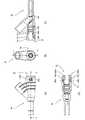


Classifications
-
- A—HUMAN NECESSITIES
- A61—MEDICAL OR VETERINARY SCIENCE; HYGIENE
- A61M—DEVICES FOR INTRODUCING MEDIA INTO, OR ONTO, THE BODY; DEVICES FOR TRANSDUCING BODY MEDIA OR FOR TAKING MEDIA FROM THE BODY; DEVICES FOR PRODUCING OR ENDING SLEEP OR STUPOR
- A61M25/00—Catheters; Hollow probes
- A61M25/01—Introducing, guiding, advancing, emplacing or holding catheters
- A61M25/06—Body-piercing guide needles or the like
- A61M25/0606—"Over-the-needle" catheter assemblies, e.g. I.V. catheters
-
- A—HUMAN NECESSITIES
- A61—MEDICAL OR VETERINARY SCIENCE; HYGIENE
- A61M—DEVICES FOR INTRODUCING MEDIA INTO, OR ONTO, THE BODY; DEVICES FOR TRANSDUCING BODY MEDIA OR FOR TAKING MEDIA FROM THE BODY; DEVICES FOR PRODUCING OR ENDING SLEEP OR STUPOR
- A61M5/00—Devices for bringing media into the body in a subcutaneous, intra-vascular or intramuscular way; Accessories therefor, e.g. filling or cleaning devices, arm-rests
- A61M5/178—Syringes
- A61M5/31—Details
- A61M5/32—Needles; Details of needles pertaining to their connection with syringe or hub; Accessories for bringing the needle into, or holding the needle on, the body; Devices for protection of needles
-
- A—HUMAN NECESSITIES
- A61—MEDICAL OR VETERINARY SCIENCE; HYGIENE
- A61M—DEVICES FOR INTRODUCING MEDIA INTO, OR ONTO, THE BODY; DEVICES FOR TRANSDUCING BODY MEDIA OR FOR TAKING MEDIA FROM THE BODY; DEVICES FOR PRODUCING OR ENDING SLEEP OR STUPOR
- A61M39/00—Tubes, tube connectors, tube couplings, valves, access sites or the like, specially adapted for medical use
- A61M39/02—Access sites
- A61M39/06—Haemostasis valves, i.e. gaskets sealing around a needle, catheter or the like, closing on removal thereof
- A61M2039/0633—Haemostasis valves, i.e. gaskets sealing around a needle, catheter or the like, closing on removal thereof the seal being a passive seal made of a resilient material with or without an opening
- A61M2039/064—Slit-valve
-
- A—HUMAN NECESSITIES
- A61—MEDICAL OR VETERINARY SCIENCE; HYGIENE
- A61M—DEVICES FOR INTRODUCING MEDIA INTO, OR ONTO, THE BODY; DEVICES FOR TRANSDUCING BODY MEDIA OR FOR TAKING MEDIA FROM THE BODY; DEVICES FOR PRODUCING OR ENDING SLEEP OR STUPOR
- A61M5/00—Devices for bringing media into the body in a subcutaneous, intra-vascular or intramuscular way; Accessories therefor, e.g. filling or cleaning devices, arm-rests
- A61M5/14—Infusion devices, e.g. infusing by gravity; Blood infusion; Accessories therefor
- A61M5/158—Needles for infusions; Accessories therefor, e.g. for inserting infusion needles, or for holding them on the body
Definitions
- the present invention relates to an indwelling needle provided with an external needle that is punctured and indwelled in a living body.
- An indwelling needle has been developed as a medical device used for infusion such as intravenous drip.
- the indwelling needle includes an inner needle that is punctured into the blood vessel of the patient and an outer needle that is inserted into the blood vessel of the patient together with the inner needle by penetrating the inner needle and puncturing the living body. ing. Then, an external needle is placed in the blood vessel of the patient, and blood is collected or infused from the patient via the external needle.
- an indwelling needle as in Patent Document 1, an indwelling needle in which a tube is provided on the side of the outer needle hub and a rubber stopper (also referred to as an elastic member) is provided at the base end of the outer needle hub is disclosed. Has been done.
- an object of the present invention is to provide an indwelling needle in which retention is unlikely to occur in the vicinity of the elastic member.
- the present invention adopts the following configuration in order to solve the above-mentioned problems.
- the indwelling needle is The inner needle that is punctured by the living body and An outer needle that is inserted into the living body together with the inner needle by penetrating the inner needle and puncturing the living body.
- An outer needle hub including a main body portion arranged along the axis of the inner needle and a branch portion branching from the main body portion and having a flow path communicating with the inside of the outer needle. It is arranged inside the outer needle hub and has a flexible solid portion that penetrates the inner needle and seals the flow of fluid to the proximal end side of the main body when the inner needle is removed. It is provided with an elastic member and a holder attached to the base end of the elastic member.
- the elastic member forms at least a part of the flow path communicating the inside of the outer needle and the branch portion, and has an end face inclined with respect to the axial direction.
- the outer needle hub is characterized by having a guide portion that engages with the elastic member or the holder and guides the axial direction of the elastic member in a certain direction.
- the elastic member can be positioned in the axial direction so that the inclined surface faces the branch portion side by the guide portion.
- the inclined surface of the elastic member makes the flow path from the tip of the outer needle hub to the branch portion smoother than before, and as a result, the fluidity of the liquid in the outer needle hub is improved, and the vicinity of the elastic member is improved. The situation where stagnation occurs is reduced.
- the elastic member has a central portion formed with the inclined end surface and an outer peripheral portion formed on the outer peripheral side of the central portion, and the outer needle hub has a tip surface of the outer peripheral portion.
- a peripheral wall portion having opposite base end surfaces is formed on the inner surface, and at least a part of the central portion is located inside the peripheral wall portion.
- the guided portion that engages with the guide portion of the present invention may be an inclined surface of the tip surface of the elastic member, or may be a concave portion or a convex portion formed on the outer surface of the elastic member. Further, the guided portion may be formed on the tip surface of the holder, or may be a concave portion or a convex portion formed on the outer surface of the holder. That is, the guide portion may be a peripheral wall portion, or may be a convex portion or a concave portion extending in the axial direction. Further, it may be a screw portion that defines the axial direction in a fixed direction.
- the guide portion is not limited to the inner surface of the outer needle hub, and may be provided on the outer surface of the outer needle hub, or a guided portion extending to the outer surface of the outer needle hub may be formed in the holder.
- an inclined surface having an inclined direction different from that of the inclined surface of the elastic member may be formed on the inner surface of the hub and the elastic member or the holder, and the axial direction of the elastic member may be set to a predetermined direction by superimposing the surfaces on each other.
- the end face of the central portion of the elastic member and the end face of the peripheral wall portion are formed so as to have a long axis and a short axis.
- the central portion can be easily positioned in the peripheral wall portion of the outer needle hub, and the elastic member can be easily defined in the predetermined axial direction.
- the long axis of the central portion of the elastic member is along the axial direction of the branch portion. In this way, it is possible to prevent the liquid from staying when the liquid moves from the branch portion to the outer needle or from the outer needle to the branch portion.
- the step between the central portion and the outer peripheral portion of the elastic member is inclined.
- the central portion can be easily positioned in the peripheral wall portion, and the fixing force can be improved by increasing the contact area with the peripheral wall portion.
- the slit formed in the central portion of the elastic member is a single character along the long axis direction of the central portion of the elastic member.
- the base end of the elastic member is externally inserted into the holder.
- the elastic member does not easily escape, and stable assembly can be realized.
- a part of the base end surface of the elastic member is a plane perpendicular to the axial direction and a surface that engages with a part of the base end surface of the elastic member is provided on the tip end surface of the holder, the elastic member is provided via the holder. It is preferable because the elastic member can be less likely to be deformed when it is moved.
- a part of the base end surface of the elastic member is an inclined surface that is inclined with respect to the axial direction, and the holder has an inclined surface that engages with the inclined surface. In this way, the relative rotation between the elastic member and the holder can be suppressed.
- a concave portion or a convex portion may be provided on a part of the base end surface of the elastic member, and a convex portion or a concave portion may be provided on the tip end surface of the holder to suppress the relative rotation between the elastic member and the holder. In this way, the relative rotation between the elastic member and the holder can be suppressed.
- the guide portion is a proximal end surface formed on the peripheral wall portion and inclined with respect to the axial direction, and the outer peripheral portion has a tip end surface that engages with the proximal end surface of the peripheral wall portion.
- the elastic member is restricted from being deformed in the proximal direction by the holder, so that when the elastic member is pushed into the outer needle hub, the elastic member becomes an elastic member when the outer peripheral portion and the peripheral wall portion come into contact with each other.
- a guide action in the axial direction occurs. Since the guide action occurs until the outer peripheral portion and the peripheral wall portion engage with each other, the elastic member is defined in a predetermined axial direction.
- the guide portion is a rotation prevention mechanism for preventing rotation of the elastic member around an axis.
- the holder has a lock portion that regulates relative movement in the axial direction with respect to the outer needle hub.
- the means for restricting the axial relative movement of the holder with respect to the outer needle hub is not limited to the lock portion, and the holder and the outer needle hub may be fixed with an adhesive or the like.
- the elastic member is compressed inward in the radial direction. By compressing in this way, liquid leakage from the slit is prevented.
- the compression may be performed by the outer needle hub or the holder.
- the central portion is compressed inward by the peripheral wall portion.
- the holder has an annular step portion adjacent to the central portion of the elastic member.
- the central portion of the elastic member that directly receives the pressure from the liquid can be less likely to be deformed toward the proximal end side, and a retention space can be less likely to be generated on the tip end side of the elastic member.
- the elastic member has a cylindrical portion extending from the outer peripheral portion toward the base end, and the holder has a small diameter portion inserted into the cylindrical portion and a large diameter portion abutting on the base end of the cylindrical portion.
- the elastic member can be stably assembled to the holder. Further, the wall thickness of the holder can be reduced to reduce the external force required for pulling out the inner needle.
- peripheral wall portion and the tip portion of the holder face each other to compress the elastic member in the axial direction.
- the holder has a mounted portion on which the elastic member is mounted.
- the elastic member is a cylindrical portion whose inner diameter side is supported by the mounted portion on the base end side of the solid portion, and is in a state before being assembled to the outer needle hub. It has a tubular portion having a thickness in the radial direction larger than the distance from the surface of the outer needle hub facing the mounted portion in the radial direction.
- the radial thickness of the tubular portion is not limited to the case where it is constant in the axial direction, and at least a part of the tubular portion in the axial direction is the mounted portion and the outer needle hub facing the mounted portion in the radial direction.
- the thickness in the radial direction may be larger than the distance from the surface.
- the indwelling needle is The inner needle that is punctured by the living body and An outer needle that is inserted into the living body together with the inner needle by penetrating the inner needle and puncturing the living body.
- An outer needle hub including a main body portion arranged along the axis of the inner needle and a branch portion branching from the main body portion and having a flow path communicating with the inside of the outer needle. It is arranged inside the outer needle hub and has a flexible solid portion that penetrates the inner needle and seals the flow of fluid to the proximal end side of the main body when the inner needle is removed.
- the elastic member forms at least a part of the flow path communicating the inside of the outer needle and the branch portion, and has an end face inclined with respect to the axial direction.
- the outer needle hub is characterized by having a guide portion that engages with the elastic member and guides the elastic member in an axial direction in a certain direction.
- the elastic member can be positioned in the axial direction so that the inclined surface faces the branch portion side by the guide portion.
- the inclined surface of the elastic member makes the flow path from the tip of the outer needle hub to the branch portion smoother than before, and as a result, the fluidity of the liquid in the outer needle hub is improved, and the vicinity of the elastic member is improved. The situation where stagnation occurs is reduced.
- the indwelling needle is The inner needle that is punctured by the living body and An outer needle that is inserted into the living body together with the inner needle by penetrating the inner needle and puncturing the living body.
- An outer needle hub including a main body portion arranged along the axis of the inner needle and a branch portion branching from the main body portion and having a flow path communicating with the inside of the outer needle. It is arranged inside the outer needle hub and has a flexible solid portion that penetrates the inner needle and seals the flow of fluid to the proximal end side of the main body when the inner needle is removed.
- the elastic member forms at least a part of the flow path communicating the inside of the outer needle and the branch portion, and has a central portion having an end surface inclined with respect to the axial direction and an outer peripheral portion. death
- the outer needle hub is characterized in that a peripheral wall portion having a base end surface facing the tip end surface of the outer peripheral portion is formed on the inner surface, and at least a part of the central portion is located on the inner surface of the peripheral wall portion.
- the present invention has a holder that is mounted on the base end of the elastic member and has a mounted portion on which the elastic member is mounted.
- the elastic member is a cylindrical portion whose inner diameter side is supported by the mounted portion on the base end side of the solid portion, and is in a state before being assembled to the outer needle hub. It has a tubular portion having a thickness in the radial direction larger than the distance from the surface of the outer needle hub facing the mounted portion in the radial direction.
- the radial thickness of the tubular portion is not limited to the case where it is constant in the axial direction, and at least a part of the tubular portion in the axial direction is the mounted portion and the outer needle hub facing the mounted portion in the radial direction.
- the thickness in the radial direction may be larger than the distance from the surface.
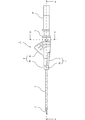
- FIG. 1 is a side view of the indwelling needle of the first embodiment.
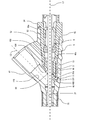
- FIG. 2 is a cross-sectional view taken along the line AA in FIG.
- FIG. 3 is a cross-sectional view taken along the line BB in FIG.
- FIG. 4 is an enlarged view of a main part of FIG.
- FIG. 5 is a cross-sectional view taken along the line DD in FIG.
- FIG. 6 is an exploded perspective view including the outer needle hub, the hemostatic valve, and the hemostatic valve holder of the first embodiment.
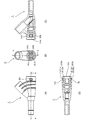
- 7 (A) to 7 (D) are views showing the configuration of an outer needle hub to which the hemostatic valve holder of the third modification is assembled.
- FIG. 8 is a side view of the hemostatic valve holder of the modified example 3.
- FIG. 9 is a perspective view of the outer needle hub, the hemostatic valve, and the hemostatic valve holder of the second embodiment.
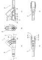
- 12 (A) to 12 (E) are views showing the configuration of an outer needle hub to which the hemostatic valve and the hemostatic valve holder of the second embodiment are assembled.
- 13 (A) to 13 (D) are views showing the configuration of an outer needle hub to which the hemostatic valve and the hemostatic valve holder of the modified example 5 are assembled.
- FIG. 14 is a diagram showing a configuration of an outer needle hub to which the hemostatic valve holder of the modified example 6 is assembled.
- FIG. 15 is a side view and an end view of the hemostatic valve holder of the modified example 6.
- FIG. 16 is a plan view of the outer needle hub of the modified example 7.
- FIG. 17 is a cross-sectional view taken along the line CC in FIG.
- FIG. 18 is a cross-sectional view taken along the line EE in FIG. 17 of the modified example 7.
- FIG. 19 is an exploded perspective view of another modified example.
- 20 (A) and 20 (B) are a plan view and a cross-sectional view of the outer needle hub to which the hemostatic valve holder of the third embodiment is assembled.
- 21 (A) and 21 (B) are a side view and a cross-sectional view taken along the line BB of the outer needle hub to which the hemostatic valve holder of the third embodiment is assembled.
- 22 (A) and 22 (B) are a perspective view and a cross-sectional view taken along the line AA of the hemostatic valve of Example 3.
- 23 (A) and 23 (B) are side views of the hemostatic valve holders of Example 3 and Reference Examples.
- 24 (A) and 24 (B) are a cross-sectional view taken along the line AA and a cross-sectional view taken along the line BB of the outer needle hub to which the hemostatic valve holder of the reference example is assembled.
- FIG. 1 shows a side view of the indwelling needle 1 according to the embodiment of the present invention.
- FIG. 2 shows a cross-sectional view of the indwelling needle 1 in FIG. 1 in the AA direction.
- FIG. 3 shows a cross-sectional view of the indwelling needle 1 shown in FIG. 1 in the BB direction in FIG.
- the indwelling needle 1 includes a hollow inner needle 2 and a cylindrical outer needle 3 provided so as to cover the outer surface of the inner needle 2.
- the inner needle 2 protrudes from the opening at the tip of the outer needle 3 and is punctured into the blood vessel of the patient (living body) to be punctured.
- the end (side / direction) in which the inner needle 2 protrudes in the indwelling needle 1 is the tip (side / direction), and the opposite end is the rear end (side / direction) or the base end (side / direction).
- the direction in which the inner needle 2 protrudes is also referred to as a puncture direction.
- the outer needle hub 4 is connected to the rear end of the outer needle 3. Inside the outer needle hub 4, a hollow portion communicating with the hollow portion 31 of the outer needle 3 is provided (see FIG. 4).
- the outer needle hub 4 has a main body 40 extending linearly along the puncture direction, that is, the axis L1 direction of the inner needle 2, which will be described later, and the main body 40 in a direction opposite to the puncture direction.
- a branch portion 41 having a Y-shape, that is, a substantially cylindrical branch portion 41 that branches in a direction inclined with respect to the axis L1 direction of the inner needle 2 is provided (FIG. 4 shows the axis L2 of the branch portion 41).
- a hollow portion 400 and a hollow portion 405 are provided inside the main body portion 40 (see FIG. 4). Further, a hollow portion 410 is provided inside the branch portion 41 (see FIG. 4).
- the hollow portion 31 of the outer needle, the hollow portions 400 and 405 of the main body portion 40, and the hollow portion 410 of the branch portion 41 communicate with each other.
- a flow path that communicates the hollow portion 31 of the outer needle 3, the hollow portion 400 of the main body 40, and the hollow portion 410 of the branch 41 is formed, and a hemostatic valve described later is formed.
- the second end surface 63 of No. 6 forms a part of this flow path.
- the outer needle hub 4 can be formed of, for example, a resin such as polypropylene, and is not particularly limited as long as it is a material generally used for medical devices.
- the outer needle hub 4 may be formed of one member or a plurality of members.
- a flexible soft tube may be arranged between the tip end and the base end of the outer needle hub 4.
- the outer needle hub 4 is not limited to the Y shape, and may be, for example, an L shape.
- the branch portion 41 may extend in the left-right direction instead of the top surface side.
- An extension tube through which blood supplied from an external device such as an artificial dialysis device passes is connected to the rear end of the branch portion 41 of the indwelling needle 1.
- An extension tube may not be provided, and a connector may be provided at the end of the port.
- blood corresponds to the fluid of the present invention.
- the hemostatic valve holder 5 that supports the hemostatic valve 6 described later and the inner needle hub 21 that holds the rear end of the inner needle 2 are connected to the rear end of the main body 40 of the indwelling needle 1.
- the hemostatic valve 6 and the hemostatic valve holder 5 correspond to the elastic member and the support member of the present invention, respectively.
- a pair of wing portions 7 are provided on the outer periphery of the indwelling needle on the tip end side of the main body portion 40 so as to sandwich the main body portion 40.
- the wing portion 7 protrudes from the side surface of the sleeve 70 in a direction orthogonal to the axial direction (front side and back side of the paper surface) and a cylindrical sleeve 70 that is fitted and mounted on the outer circumference of the tip side of the main body portion 40. It has a plate-shaped portion 71 to be formed.
- the sleeve 70 is fixed to the main body so as not to move in the axial direction or the axial direction.
- the wing portion 7 functions as a gripping portion for the operator to grip when using the indwelling needle 1, and also functions as a fixing portion for fixing the indwelling needle 1 to the body with tape or the like.
- the wing portion extends in a direction intersecting the extending direction of the branch portion, it may extend in a direction parallel to the branch portion.
- the sleeve 70 may be provided so as to be relatively rotatable in the axial direction with respect to the main body portion, and in that case, the user can position the wing portion at a suitable position. Further, it is not necessary to provide the wing portion.
- an outer needle holding portion 401 for holding the base end side of the outer needle 3 is provided on the tip end side of the main body portion 40 of the outer needle hub 4.
- the tip of the outer needle holding portion 401 is provided with a tip opening 402 that opens in the puncture direction.
- the outer needle 3 is held by the outer needle holding portion 401 so that its tip protrudes from the tip opening 402.
- the base end side of the outer needle 3 is fixed by a caulking pin 403 that crimps between the outer needle 3 and the outer needle hub 4.
- a hemostatic valve 6 is attached to the tip of the hemostatic valve holder 5. Then, the inner needle hub 21 is connected to the rear end side of the hemostatic valve holder 5. The inner needle hub 21 holds the base end side of the inner needle 2 on the tip end side. Further, a protector 8 for protecting the needle tip 2a of the inner needle 2 is attached to the tip end side of the inner needle hub 21.
- the protector 8 has a protector main body 80 and a protector holder 81.
- the protector body 80 is configured to cover and protect the needle tip 2a of the inner needle 2, and is made of various metals such as stainless steel, aluminum, aluminum alloy, titanium alloy, copper, copper alloy, and copper alloy. Consists of materials.
- the protector main body 80 can be configured as, for example, a roughly square columnar member obtained by bending and deforming the above-mentioned thin-walled metal material plate. As shown in FIG. 3, the protector main body 80 mainly includes a substantially square bottom plate portion 80a and flexible protective pieces 80b and 80c extending from two opposite sides of the bottom plate portion 80a toward the tip.
- the inner needle 2 is inserted into a hole formed in the center of the bottom plate portion 80a, and the protector main body 80 is supported so as to be movable in the axial direction of the inner needle 2.
- the protective piece 80b and the protective piece 80c are substantially rectangular plate-shaped members, and face each other with the inner needle 2 interposed therebetween.
- the protective piece 80b and the protective piece 80c are bent in a direction away from each other (outer diameter direction of the inner needle 2) from the bottom plate portion 80a toward the tip side, and then bent in a direction approaching each other (inner diameter direction of the inner needle 2). It has a substantially J-shape that bends toward the rear end side in the direction of approaching each other on the front end side.
- the protective piece 80b is formed longer than the protective piece 80c, and the tip end portion of the protective piece 80b is located closer to the tip end portion than the tip end portion of the protection piece 80c.
- the protector holder 81 is a roughly tubular member made of synthetic resin.
- the protector holder 81 has a cylindrical portion 81a on the front end side, an accommodating portion 81b on the rear end side, and a ring portion 81c on the rear end portion of the accommodating portion 81b.
- the cylindrical portion 81a is formed in a substantially cylindrical shape, is inserted through the opening on the rear end side of the hemostatic valve holder 5, is housed in the hollow portion of the hemostatic valve holder 5, and is stopped by an engaging means such as unevenness (not shown). It is locked to the valve holder 5.
- the accommodating portion 81b is formed in the shape of a square cylinder having a substantially square cross section, and the tip end side is integrally formed with the rear end of the cylindrical portion 81a.
- a substantially rectangular opening is formed in a pair of side walls (two side walls in the vertical direction in FIG. 3) of the accommodating portion 81b facing each other. These openings are provided on the opposite side of the inner needle 2 with respect to the protective piece 80b and the protective piece 80c, and the protective piece 80b and the protective piece 80c are deformed in a direction away from each other by these openings. Is allowed.
- the ring portion 81c is formed in an annular shape having a square cross section composed of four side walls.
- the dimension of the inner peripheral portion of the ring portion 81c is formed so as to substantially match the external dimension of the bottom plate portion 80a of the protector main body 80.
- the protector main body 80 is moved so as to be pulled out from the ring portion 81c, and when the protective piece 80b and the protective piece 80c of the protector main body 80 are passed through the ring portion 81c, the protective piece 80b and the protective piece 80c are inside by the ring portion 81c. Pushed into.
- the protective piece 80b and the protective piece 80c are elastically deformed so as to approach each other, the opposing protective pieces 80b and 80c come into contact with each other, and the gap between them is closed. At this time, the protective piece 80b and the deformed portion of the protective piece 80c protrude from the opening of the accommodating portion 81b. In this way, since the protective piece 80b and the protective piece 80c cannot move in a direction closer to each other, the movement of the protector main body 80 is regulated by the rear end side portion of the protective piece 80b and the protective piece 80c, and the protector main body 80 is restricted. Cannot be removed from the protector holder 81.
- the protector main body 80 By moving the protector main body 80 in the direction of pulling out from the protector holder 81 in this way, the needle tip 2a of the inner needle 2 is covered and protected by the protector main body 80, and the protector main body 80 cannot be moved relative to the protector holder 81. , The protected state is maintained.
- the protector main body 80 including the protector body 80 moves to the rear end side.
- the protector main body 80 moves relative to the protector holder 81 toward the rear end side as described above, so that the protective piece 80b and the protective piece 80c that come into contact with each other move with respect to the inner needle 2.
- the needle tip 2a can be covered and protected.
- FIG. 4 is an enlarged view showing a main part of the cross-sectional view shown in FIG.
- FIG. 5 is a cross-sectional view taken along the line DD of FIG.
- FIG. 6 is an exploded perspective view of the outer needle hub 4, the hemostatic valve 6, and the hemostatic valve holder 5.
- the axis L1 is a line indicating the axial direction of the main body 40 of the outer needle hub 4, and when the inner needle 2 is inserted into the outer needle 3, it coincides with the axis of the inner needle 2.
- the outer needle hub 4 is provided with a hollow portion 400 communicating with the hollow portion 31 of the outer needle 3.
- the hollow portion 405 on the rear end side in the axis L1 direction from the hollow portion 400 and the hollow portion 410 inclined from the hollow portion 400 in the axis L1 direction communicate with each other via the hollow portion 400.
- a hemostatic valve 6 and a hemostatic valve holder 5 are attached to the hollow portion 405.
- An inner needle hub 21 equipped with the protector 8 is attached to the rear end side of the hemostatic valve holder 5.
- the inner needle 2 pushes open the slit 64 of the hemostatic valve 6 and is inserted into the hollow portion 31 of the outer needle 3.
- the hemostatic valve 6 is formed of, for example, a synthetic rubber such as polyisoprene or a thermoplastic elastomer.
- the hemostatic valve holder 5 can be formed of, for example, a resin such as polypropylene, and is not particularly limited as long as it is a material generally used for medical devices.
- the hemostatic valve 6 is formed in a substantially bottomed cylindrical shape.
- the end of the hemostatic valve 6 on the distal end side is formed on a slope inclined with respect to the axis L1 direction.
- the hemostatic valve 6 is connected to the cylindrical portion 60, the annular first end surface 61 connected to the end edge on the distal end side of the cylindrical portion 60, and the inner diameter side of the first end surface 61 in the axis L1 direction.
- An annular step portion 62 extending and a disk-shaped second end surface 63 connected to the inner diameter side of the step portion 62 are included.
- the first end surface 61 and the second end surface 63 of the hemostatic valve 6 are configured to be substantially parallel to each other, and are similarly inclined with respect to the axis L1 direction.
- a linear slit 64 is provided in the center of the second end surface 63 so as to penetrate the flexible solid portion 631 from the front end side to the rear end side.
- the shape of the slit may be a cross shape, a Y shape, or the like.
- the central base end surface 66 which is the surface on the rear end side of the first end surface 61 and the second end surface 63 of the hemostatic valve 6, is formed on a single surface parallel to the first end surface 61.
- the shape of the second end surface 63 of the hemostatic valve 6 is not limited to a flat surface, and may be formed into a curved surface that follows the cylindrical surface shape of the peripheral wall of the hollow portion 410 of the branch portion 41. It can also be said that the second end surface 63 is also the central portion of the hemostatic valve 6, and the first end surface 61 is the outer peripheral portion formed on the outer periphery of the central portion. Further, the hemostatic valve 6 may have a shape such that the second end surface 63 and the step portion 62 have a long axis on the straight line La and a short axis on the straight line Sa indicated by the dotted line in FIG.
- the opening 404 of the outer needle hub 4 is also shaped to have a long axis and a short axis. Since the central portion of the hemostatic valve 6 and the opening 404 of the outer needle hub 4 have a major axis and a minor axis, they function as an outer peripheral portion and a guided portion, making it easier to position the hemostatic valve 6 in a predetermined direction around the axis. be able to. Further, when the second end surface 63 and the step portion 62 have a shape having a major axis and a minor axis in this way, the major axis is set in a direction along the axis L2 direction of the branch portion 41 from the viewpoint of miniaturization. Is desirable.
- the second end surface 63 has a shape having a major axis and a minor axis in this way, it is desirable to form a linear slit along the major axis direction.
- the step portion 62 formed between the first end surface 61 and the second end surface 63 is inclined with respect to the axis L1 direction, and when the central portion of the hemostatic valve 6 is inserted into the opening 404 of the outer needle hub 4. It is easy to insert in. Further, the rear end side of the hemostatic valve 6 is opened in a cylindrical shape, and the center is thinned with respect to the outer peripheral portion to reduce the resistance when the inner needle is pulled out.
- the end surface 65 on the rear end side of the hemostatic valve 6 forms a plane orthogonal to the axis L1 direction, and abuts on the step portion 52a of the hemostatic valve holder 5. By doing so, it is possible to reduce that the elastic valve body is unintentionally deformed when the hemostatic valve 6 is relatively moved in the outer needle hub.
- the hemostatic valve holder 5 is formed in a substantially cylindrical shape.
- the hemostatic valve holder 5 includes a small diameter portion 51, an enlarged diameter portion 52, a large diameter portion 53, and a flange portion 54 in this order from the tip end side.
- An annular first end surface 51a that is connected to the inner diameter side of the edge of the small diameter portion 51 and is inclined with respect to the axis L1 direction is formed at the end portion on the tip end side of the small diameter portion 51.
- An annular step portion 51b is formed which is connected to the inner diameter side of the first end surface 51a and extends in the axis L1 direction.
- a second end surface 51c that is connected to the inner diameter side of the step portion and is inclined with respect to the axis L1 direction is formed.
- the first end surface 51a and the second end surface 51c of the hemostatic valve holder 5 are configured to be substantially parallel to each other, and are similarly inclined with respect to the axis L1 direction. Further, the first end surface 51a and the second end surface 51c of the hemostatic valve holder 5 are configured to be parallel to the first end surface 61 and the second end surface 63 of the hemostatic valve 6, respectively, and are similarly inclined in the axis L1 direction. There is.
- the annular step portion 51b may be provided so as to be inclined with respect to the axis L1 direction in order to increase the contact area with the hemostatic valve 6. Further, it is desirable that the tip end portion of the second end surface 51c is formed in an R shape.
- the rear end side of the small diameter portion 51 is connected to the diameter expansion portion 52 that expands in diameter toward the rear end side via the step portion 52a extending in the direction orthogonal to the outer diameter side, that is, the axis L1.
- the rear end side of the enlarged diameter portion 52 is connected to the large diameter portion 53.
- an annular flange portion 54 projecting to the outer diameter side is formed on the rear end side of the large diameter portion 53.
- protrusions 55a and 55b (see FIG. 5) that gradually project from the front end side to the rear end side toward the outer diameter side are formed.
- the protrusions 55a and 55b are provided at positions symmetrical with respect to the axis L1.
- a rib 56 is formed on the side surface of the large diameter portion 53 so as to project toward the outer diameter side and extend from the front end side to the rear end side in the axis L1 direction, and the rear end side of the rib 56 is connected to the flange portion 54.
- the rib 56 is provided between the protrusion 55a and the protrusion 55b, and is provided at a position opposite to the branch portion 41 with respect to the axis L1 direction in relation to the outer needle hub 4.
- the outer diameter dimension of the small diameter portion 51 of the hemostatic valve holder 5 is set to be slightly smaller than the inner diameter dimension of the cylindrical portion 60 of the hemostatic valve 6.
- the hemostatic valve 6 with respect to the hemostatic valve holder 5 is inclined in the axis L1 direction and the axis L1 direction. It regulates the displacement in the rotation direction around the axis L1 and also functions as a guide when assembling the hemostatic valve 6 and the hemostatic valve holder 5 in the predetermined axial direction.
- the dimensions of the cylindrical portion 60 of the hemostatic valve 6 and the small diameter portion 51 of the hemostatic valve holder 5 in the axis L1 direction are set so that the end surface 65 of the hemostatic valve holder 5 abuts on the step portion 52a of the hemostatic valve holder 5.
- the hemostatic valve holder 5 When the small diameter portion 51 of the hemostatic valve holder 5 is pushed into the hemostatic valve 6 to a position where the step portion 52a of the hemostatic valve holder 5 comes into contact with the end surface of the cylindrical portion 60 of the hemostatic valve 6 on the rear end side, the hemostatic valve holder 5 The stepped portion 51b and the second end surface 51c of the small diameter portion 51 slightly bite into the rear end side of the second end surface 63 of the hemostatic valve 6. Since both the hollow portion of the hemostatic valve 6 and the small diameter portion 51 of the hemostatic valve holder 5 are formed in a shape that is rotationally asymmetric with respect to the axis L1, the hemostatic valve 6 is formed by the small diameter portion 51 of the hemostatic valve holder 5.
- the shape of the small diameter portion of the hemostatic valve holder 5 is not limited to the cylindrical shape.
- FIG. 4 shows a state in which the hemostatic valve 6 and the hemostatic valve holder 5 are appropriately positioned with respect to the outer needle hub 4.
- An opening 404 is provided on the tip end side of the hollow portion 405 of the main body portion 40 of the outer needle hub 4 via the step portion 406.
- the inner diameter of the opening 404 in the direction orthogonal to the axis L1 is set smaller than the inner diameter of the hollow portion 405.
- the inner diameter of the hollow portion 405 is such that the outer peripheral surface of the hemostatic valve holder 5 to which the hemostatic valve 6 is attached is pressed against the inner peripheral surface of the hollow portion 405, and the hemostatic valve 6 and the hemostatic valve are between the hollow portion 400 and the hollow portion 405.
- the inner peripheral surface of the hollow portion 405 on the distal end side is formed in a cylindrical shape corresponding to the cylindrical portion 60 of the hemostatic valve 6, and the rear end side corresponds to the enlarged diameter portion 52 of the hemostatic valve holder 5 and is the rear end. It is formed in a tapered shape that expands toward the outer diameter side toward the side, and the rear end side is formed in a cylindrical shape corresponding to the large diameter portion 53 of the hemostatic valve holder 5.
- the portion of the outer needle hub 4 including the step portion 406 and the opening 404 may be formed of a separate member from the other portion of the outer needle hub 4, and by fixing the separate member to the outer needle hub 4. It may be integrated.
- the hemostatic valve 6 and the hemostatic valve holder 5 are appropriately positioned with respect to the outer needle hub 4, the first end surface 61 and the step portion 62 of the hemostatic valve 6 are the outer needle hub 4.
- the hemostatic valve 6 abuts on the inner peripheral surfaces of the step portion 406 and the opening 404, respectively, and the hemostatic valve 6 is located between the step portion 406 of the outer needle hub 4 and the first end surface 51a of the hemostatic valve holder 5 facing each other. It is compressed and fixed in the direction. Then, the second end surface 63 of the hemostatic valve 6 is exposed to the hollow portion 400 side.
- the second end surface 63 of the hemostatic valve 6 is set to have substantially the same height as the portion of the inner peripheral surface of the hollow portion 410 of the branch portion 41 that is adjacent to the opening 404. In this way, the hemostatic valve 6 has the outer peripheral portion firmly fixed, the central portion fills the gap in the outer needle hub 4, and the inner peripheral surface of the hollow portion 410 in the hollow portion 410 branching from the hollow portion 400. Since a sudden shape change does not occur at the portion of the second end surface 63 of the hemostatic valve 6 which constitutes a part of the outer needle 3, the hollow portion 31 of the outer needle 3 and the hollow portion 40 of the main body portion 40 of the outer needle hub 4 are hollow.
- the step portion 406 and the opening portion 404 of the outer needle hub 4 function as a peripheral wall portion with respect to the second end surface 63 which is the central portion on the tip end side of the hemostatic valve 6, and the step portion 406 engages with the first end surface. It constitutes the base end surface of the peripheral wall portion.
- the step portion 406 inclined in the axis L1 direction constitutes a guide portion, and the tip surface of the hemostatic valve 6 constitutes a guided portion.
- the hemostatic valve 6 when the hemostatic valve 6 is appropriately positioned with respect to the outer needle hub 4, the distance between the portions 62a and 62b facing each other across the slit 64 of the step portion 62 of the hemostatic valve 6 corresponds to the opening 404.
- the portion of the hemostatic valve 6 including these portions 62a and 62b is set to be slightly larger than the inner diameter of the portion to be formed, and is tightly fitted to the opening 404.
- the opening 404 of the outer needle hub 4 exerts a force that compresses the slit 64 of the hemostatic valve 6 in the closing direction. The elastic recovery force is increased, and the sealing property of the hemostatic valve 6 can be ensured.
- the hemostatic valve 6 is compressed toward the inner diameter side by the inner circumference of the opening 404 as described above, but the mode of compression is not limited to the above.
- the hemostatic valve 6 is formed to have a thick wall thickness so that the central base end surface 66 of the hemostatic valve 6 is perpendicular to the axial direction, and compression is applied inward in the radial direction from the outer needle hub 4. It is also possible to secure the sealing property of. Further, the wall thickness of the hemostatic valve 6 can be further increased to ensure the sealing property of the hemostatic valve 6 without applying compression.
- an inclined surface inclined in the axial direction is provided at a contact portion of the hemostatic valve holder 5 with the outer needle hub 4, and an inclined surface that engages with the inclined surface is provided on the inner surface of the outer needle hub 4 to provide a guide portion and an inclined surface.
- the guided portion may be formed, and the axial direction of the outer needle hub 4 and the hemostatic valve holder 5 may be defined.
- a rectangular opening 42a and an opening 42b are provided on the side surface of the outer needle hub 4 on the rear end side of the main body 40.
- the opening 42a and the opening 42b are provided at positions symmetrical with respect to the axis L1.
- a notch 43 having an open rear end side is provided on the rear end side of the main body 40 of the outer needle hub 4.
- the notch 43 is provided between the opening 42a and the opening 42b, and is provided at a position opposite to the branch portion 41 with respect to the axis L1.
- the hemostatic valve holder 5 to which the hemostatic valve 6 is attached is press-fitted from the opening on the rear end side of the outer needle hub 4 and attached to the outer needle hub 4, the opening 42a and 42b of the outer needle hub 4 are attached.
- the protrusion 55a, the protrusion 55b, and the rib 56 of the hemostatic valve holder 5 are held in a corresponding posture with respect to the notch 43.
- the hemostatic valve holder 5 is advanced with respect to the outer needle hub 4 in the direction of the axis L1 and press-fitted from the opening on the rear end side, and the protrusion 55a, the protrusion 55b, and the rib 56 are formed into the opening 42a and the opening 42b, respectively.
- the hemostatic valve holder 5 is guided in the axis L1 direction with respect to the outer needle hub 4 by the notch 43 and the rib 56. In this way, when the hemostatic valve 6 and the hemostatic valve holder 5 are attached to the outer needle hub 4, the direction around the axis around the axis L1 of the hemostatic valve 6 and the hemostatic valve holder 5 with respect to the outer needle hub 4 is a predetermined direction. Can be.
- the direction around the axis L1 of the hemostatic valve 6 and the hemostatic valve holder can be guided in a certain direction, whereby the direction around the axis L1 of the hemostatic valve 6 mounted on the hemostatic valve holder 5 can be defined.
- the hemostatic valve 6 and the hemostatic valve holder 5 for the outer needle hub 4 are provided with the above-mentioned protrusions 55a, protrusions 55b, ribs 56, and rotation prevention mechanisms such as the opening 42a, the opening 42b, and the notch 43. It is possible to prevent rotation around the axis L1 of.
- the rotation prevention mechanism may be composed of only the rib 56 and the notch 43.
- the protrusions 55a and 55b of the hemostatic valve holder 5 are fitted with the openings 42a and 42b of the outer needle hub 4 to form a lock portion that regulates the relative movement of the outer needle hub 4 in the axis L1 direction.
- the hemostatic valve holder 5 and the outer needle hub 4 are provided with a rotation prevention mechanism for attaching the hemostatic valve 6 and the hemostatic valve holder 5 to the outer needle hub 4
- the hemostatic valve holder 5 is provided with a protrusion 55a, a protrusion 55b, and a rib 56
- the outer needle hub 4 is provided with an opening 42a, an opening 42b, and a notch 43.
- the hemostatic valve holder 5 may be provided with an opening, a notch or a recess, and a protrusion or a rib may be provided on the inner peripheral surface of the hollow portion 405 of the outer needle hub 4.
- the central base end surface 66 of the hemostatic valve 6 and the first end surface 51a at the tip of the hemostatic valve holder 5 are inclined to restrict the relative rotation of the hemostatic valve 6 and the hemostatic valve holder 5.
- the central base end surface 66 of the hemostatic valve 6 and the first end surface 51a at the tip of the hemostatic valve holder 5 do not have to be inclined, and the hemostatic valve is provided with notches, recesses, protrusions, etc. Relative rotation may be restricted by providing the hemostatic valve holder with a convex portion or the like that engages with the convex portion.
- the small diameter portion of the hemostatic valve 6 and the hemostatic valve holder 5 may act between the 51 and the 51.
- the hemostatic valve 6 and the small diameter portion 51 of the hemostatic valve holder 5 may be formed of a material that causes frictional force with each other.
- a member that generates a frictional force may be interposed between the hemostatic valve 6 and the small diameter portion 51 of the hemostatic valve holder 5. It may be fixed with an adhesive. The cause of the frictional force between the hemostatic valve 6 and the small diameter portion 51 of the hemostatic valve holder 5 is not limited to the intermolecular force.
- FIG. 7A is a side view of the outer needle hub 4 to which the hemostatic valve holder 15 is assembled
- FIG. 7B is a side view of the outer needle hub 4 to which the hemostatic valve holder 15 is assembled in the axis L1 direction. It is an end view seen from the base end side along the line
- FIG. 7C is a cross-sectional view taken along the line AA of the outer needle hub 4 to which the hemostatic valve holder 15 is assembled
- FIG. 7D is a B of the outer needle hub 4 to which the hemostatic valve holder 15 is assembled. -B direction sectional view.
- FIG. 8 is a side view of the hemostatic valve holder 15.
- the hemostatic valve holder 15 has a small diameter portion 51, an enlarged diameter portion 52, and a large diameter portion 53, as in the first embodiment.
- a collar-shaped end portion 151 projecting to the outer diameter side and an outer end portion 151 are provided on the rear end side of the large diameter portion 53.
- a substantially cylindrical external portion 152 extending from the edge portion on the radial side toward the tip end side in parallel with the large diameter portion 53 and covering the outer peripheral side of the large diameter portion 53 is provided.
- the extrapolation portion 152 is provided with a claw 153a and a claw 153b at positions symmetrical with respect to the axis L1.
- the substantially rectangular claws 153a and 153b are joined to the extrapolation portion 152 on the rear end side, and are provided so as to be elastically deformable in the radial direction with the rear end side as a fulcrum.
- a triangular protrusion 154a and a protrusion 154b are provided.
- a rectangular opening 42a and an opening 42b are provided on the rear end side of the main body 40 of the outer needle hub 4, as in the embodiment.
- a cylindrical gap 155 is formed between the extrapolation portion 152 of the hemostatic valve holder 5 and the large diameter portion 53, and the hemostatic valve holder 15 is provided in the small diameter portion 51 in the opening at the rear end of the outer needle hub 4.
- the protrusions 154a and 154b of the hemostatic valve holder 5 are fitted into the openings 42a and 42b of the outer needle hub 4 from the outer diameter side, so that the direction around the axis L1 of the hemostatic valve holder 5 can be changed. It can be guided in a certain direction. Therefore, the axial direction L1 of the hemostatic valve 6 mounted on the hemostatic valve holder 5 can be defined. Therefore, the blood flowing from the outer needle 3 into the outer needle hub 4 can be smoothly moved to the branch portion 41, and the retention in the vicinity of the hemostatic valve 6 can be prevented.
- the opening 42a and the opening 42b of the outer needle hub 4 form a guide portion.
- the protrusions 154a and 154b form a guided portion, and the openings 42a and 42b of the outer needle hub 4 and the protrusions 154a and 154b of the hemostatic valve holder 5 form an anti-rotation mechanism. Further, the protrusions 154a and 154b of the hemostatic valve holder 15 are fitted with the opening 42a and the opening 42b in the outer needle hub 4 to provide a lock portion that regulates the relative movement of the hemostatic valve holder 15 in the axis L1 direction with respect to the outer needle hub 4. Constitute.
- the opening 42a and the opening 42b may be recesses formed on the outer surface of the outer needle hub 4.
- the outer needle hub 4 is provided with an opening 42a and an opening 42b, and the hemostatic valve holder 15 is provided with a protrusion 154a and a protrusion 154b.
- the outer needle hub 4 is provided with a protrusion and the hemostatic valve holder 15 is provided with a protrusion.
- An opening may be provided.
- FIG. 9A is a side view of the outer needle hub 4 to which the hemostatic valve holder 25 is assembled
- FIG. 9B is a side view of the outer needle hub 4 to which the hemostatic valve holder 25 is assembled along the axis L1. It is an end view seen from the base end side
- FIG. 9C is a cross-sectional view taken along the line AA of the outer needle hub 4 to which the hemostatic valve holder 25 is assembled
- FIG. 9D is a B of the outer needle hub 4 to which the hemostatic valve holder 25 is assembled.
- -B direction sectional view.
- FIG. 10A is a side view of the hemostatic valve holder 25, and FIG. 10B is an end view of the hemostatic valve holder 25 as viewed from the proximal end side.
- the hemostatic valve holder 25 has a small diameter portion 51 and an enlarged diameter portion 52, as in the first embodiment.
- the claws 251a and the claws 251b are provided on the rear end side of the enlarged diameter portion 52 at positions symmetrical with respect to the axis L1.
- the claws 251a and 251b extend in the axis L1 direction from the rear end of the enlarged diameter portion 52.
- the claws 251a and 251b are connected to the rear end portion of the enlarged diameter portion 52, respectively, and have a partial cylindrical shape that follows the shape of the rear end portion.
- the protrusion 2512a has a triangular cross section having a slope 25121a protruding from the front end side toward the rear end side and an end surface 25122a connected to the rear end side of the slope 25121a and orthogonal to the axis L1 direction.
- the protrusion 2512b has a triangular cross section having a slope 25121b and an end surface 25122b.
- the hemostatic valve holder 25 has a partial cylindrical portion 252a and a partial cylindrical portion 252b that are sandwiched between the claws 251a and 251b in the circumferential direction and are connected to the rear end portion of the enlarged diameter portion 52 and follow the shape of the rear end portion. It is provided at a position symmetrical with respect to the axis L1. A gap is formed between each of the claws 251a and 251b and the partial cylindrical portion 252a and the partial cylindrical portion 252b in the circumferential direction.
- a rectangular opening 42a and an opening 42b are provided on the rear end side of the main body 40 of the outer needle hub 4, as in the embodiment.
- the claws 251a and 251b are pressed toward the inner diameter side, and the inner diameter side with the base as a fulcrum. Elastically deforms to.
- the hemostatic valve holder 25 When the hemostatic valve holder 25 is further pushed into the outer needle hub 4 toward the tip side and the protrusions 2512a and 2512b reach the positions of the openings 42a and 42b of the outer needle hub 4, the claws 251a and the claws Due to the elastic return of 251b, the protrusion 2512a and the protrusion 2512b are fitted into the opening 42a and the opening 42b from the inner diameter side, respectively.
- the protrusions 2512a and 2512b of the hemostatic valve holder 25 are fitted into the openings 42a and 42b of the outer needle hub 4 from the inner diameter side, so that the direction around the axis L1 of the hemostatic valve holder 25 is constant. Can be guided in the direction. Therefore, the axial direction L1 of the hemostatic valve 6 mounted on the hemostatic valve holder 25 can be defined. Therefore, the blood flowing from the outer needle 3 into the outer needle hub 4 can be smoothly moved to the branch portion 41, and the retention in the vicinity of the hemostatic valve 6 can be prevented.
- the opening 42a and the opening 42b of the outer needle hub 4 form a guide portion.
- the protrusions 2512a and 2512b form a guided portion, and the openings 42a and 42b of the outer needle hub 4 and the protrusions 2512a and 2512b of the hemostatic valve holder 5 form a rotation prevention mechanism. Further, the protrusions 2512a and 2512b of the hemostatic valve holder 25 are fitted with the openings 42a and 42b of the outer needle hub 4 to form a lock portion that regulates the relative movement of the outer needle hub 4 in the axis L1 direction. Constitute.
- the claws 251a and 251b provided at positions symmetrical with respect to the axis L1 are provided with the protrusions 2512a and 2512b, but the hemostatic valve holder 25 has a cylindrical shape on the rear end side of the enlarged diameter portion 52.
- a large-diameter portion may be provided, and a flange having a triangular cross section may be provided on the outer peripheral surface of the large-diameter portion so as to project in the outer diameter direction over the entire circumference. In this case, a part of the flange is fitted into the opening 42a and the opening 42b of the outer needle hub 4, respectively.
- Example 2 The indwelling needle according to the second embodiment of the present invention will be described below.
- the same reference numerals are used and detailed description thereof will be omitted.
- FIG. 11 is an exploded perspective view of the outer needle hub 34, the hemostatic valve holder 35, and the hemostatic valve 6 according to the second embodiment.
- FIG. 12A is a side view showing a state in which the hemostatic valve 6 and the hemostatic valve holder 35 are assembled to the outer needle hub 34 according to the second embodiment
- FIG. 12B is the hemostatic valve 6 and the hemostatic valve holder.
- FIG. 5 is an end view of the outer needle hub 34 to which the 35 is assembled as viewed from the base end side along the axis L1 direction.
- FIG. 12C is a cross-sectional view in the CC direction of the outer needle hub 34 to which the hemostatic valve 6 and the hemostatic valve holder 35 are assembled, and FIG.
- FIG. 12D is a cross-sectional view in the CC direction in which the hemostatic valve 6 and the hemostatic valve holder 35 are assembled. It is a DD direction sectional view of the said outer needle hub 34.
- FIG. 12 (E) is a cross-sectional view taken along the line AA of the outer needle hub 34 to which the hemostatic valve 6 and the hemostatic valve holder 35 are assembled.
- a substantially rectangular opening 342a and an opening 342b are provided on the rear end side of the main body 40 of the outer needle hub 34 according to the second embodiment.
- the opening 342a and the opening 342b are provided at positions symmetrical with respect to the axis L1.
- a substantially rectangular parallelepiped protrusion 343 that protrudes in the axis L1 direction from the end surface 407 on the rear end side of the main body 40 of the outer needle hub 34 is provided.
- the protrusion 343 is provided between the opening 342a and the opening 342b, and is provided at a position on the side where the branch portion 41 branches with respect to the axis L1.
- the opening 342a and the opening 342b of the outer needle hub 34 are provided with substantially rectangular claws 344a and 344b, respectively, so as to be elastically deformable.
- the claws 344a and 344b are formed so that the front end side is bent toward the inner diameter side, and the claw 344a and the claw 344b are connected to the main body 40 on the rear end side.
- a hollow portion 3405 is provided on the rear end side of the hollow portion 400 inside the outer needle hub 4.
- the inner diameter of the hollow portion 3405 is substantially constant in the axis L1 direction.
- a hollow portion 3407 having an inner diameter larger than that of the hollow portion 3405 is provided on the rear end side of the hollow portion 3405 via a hollow portion 3406 whose diameter is expanded to the outer diameter side.
- the opening 342a and the opening 342b are opened from the hollow portion 3406 to the hollow portion 3407 so as to penetrate the outer needle hub 34 in the outer diameter direction.
- the hemostatic valve holder 35 has a small diameter portion on the rear end side of the small diameter portion 51 similar to the first embodiment via an end surface 352a in a direction orthogonal to the axis L1 direction.
- a cylindrical medium-diameter portion 352 having a diameter larger than 51 and having a constant diameter in the axis L1 direction is connected.
- a flange portion 353 having a first diameter expansion portion 3531 that expands in diameter toward the rear end side and an end surface 3532 in a direction orthogonal to the axis L1 direction is provided over the entire circumference.
- a cylindrical second middle diameter portion 354 having substantially the same diameter as the middle diameter portion 352 is connected.
- a second diameter expansion portion 355 whose diameter is expanded toward the rear end side is provided over the entire circumference, and is continuous with the second diameter expansion portion 355 and has a medium diameter.
- a cylindrical large-diameter portion 356 having a diameter larger than that of the portion 352 and the second medium-diameter portion 354 and having a diameter substantially equal to that of the flange portion 353 is provided.
- An annular collar portion 357 protruding toward the outer diameter side is formed at the rear end portion of the large diameter portion 356.
- a recess 3571 that is concave from a part of the end face 357a on the tip end side toward the rear end side is provided.
- the recess 3571 opens from the end surface 357a on the distal end side of the flange portion 357 to the outer peripheral surface 357b.
- the recess 3571 is provided at a position opposite to the side on which the inclined first end surface 51a of the small diameter portion 51 projects toward the tip end side with respect to the axis L1.
- the hemostatic valve holder 35 to which the hemostatic valve 6 is attached is press-fitted from the opening at the rear end of the outer needle hub 34 and attached to the outer needle hub 34.
- the tip portions 3441a and 3441b of the claws 344a and 344b come into contact with the first enlarged diameter portion 3531 of the flange portion 353 of the hemostatic valve holder 35 to the outside. It is pressed to the radial side and elastically deforms.
- the tip portions 3441a and 3441b of the claws 344a and 344b move over the first enlarged diameter portion 3531 of the flange portion 353 of the hemostatic valve holder 35. Rubbing. Then, when the hemostatic valve holder 35 is properly positioned in the outer needle hub 34, the tip portions 3441a and 3441b of the claws 344a and 344b get over the first enlarged diameter portion 3531 of the flange portion 353 of the hemostatic valve holder 35. .. As shown in FIG.
- the first enlarged diameter portion 3531 of the flange portion 353 of the hemostatic valve holder 35 is the hollow portion 3406 of the outer needle hub 34. It faces the inner peripheral surface and comes into contact with it. At this time, the large diameter portion 356 of the hemostatic valve holder 35 faces and contacts the hollow portion 3407 of the outer needle hub 34. Further, when the hemostatic valve holder 35 is properly positioned in the outer needle hub 34, the protrusion 343 of the outer needle hub fits into the recess 3571 of the flange portion 357 of the hemostatic valve holder 35.
- the claws 344a and claws 344b of the outer needle hub 34 are fitted into the recesses formed by the flange portion 353, the second middle diameter portion 354, and the second diameter expansion portion 355 of the hemostatic valve holder 5, and are fitted to the outer diameter.
- the protrusion 343 of the needle hub 34 into the recess 3571 in the axis L1 direction, the hemostatic valve holder 35 can be guided in a certain direction around the axis L1. Therefore, the axial direction L1 of the hemostatic valve 6 mounted on the hemostatic valve holder 35 can be defined. Therefore, the blood flowing from the outer needle 3 into the outer needle hub 4 can be smoothly moved to the branch portion 41, and the retention in the vicinity of the hemostatic valve 6 can be prevented.
- the claws 344a and 344b of the outer needle hub 34 and the flange portion 353 of the hemostatic valve holder 35 define the axial relative positions of the hemostatic valve and the hemostatic valve holder with respect to the outer needle hub.
- the protrusion 343 and the recess 3571 define the relative positions of the hemostatic valve and the hemostatic valve holder in the axial direction with respect to the outer needle hub. That is, the protrusion 343 constitutes the guide portion and the lock portion, the recess 3571 forms the guided portion, and both form the rotation prevention mechanism.
- FIG. 13 (A) is a plan view showing a state in which the hemostatic valve 6 and the hemostatic valve holder 75 are assembled to the outer needle hub 74 according to the modified example 5, and FIG. 13 (B) shows the hemostatic valve 6 and the hemostatic valve.
- FIG. 13 (A) is a plan view showing a state in which the hemostatic valve 6 and the hemostatic valve holder 75 are assembled to the outer needle hub 74 according to the modified example 5, and
- FIG. 13 (B) shows the hemostatic valve 6 and the hemostatic valve.
- FIG. 5 is a cross-sectional view taken along the line AA of the outer needle hub 74 to which the holder 75 is assembled.
- FIG. 13C is a side view showing a state in which the hemostatic valve 6 and the hemostatic valve holder 75 are assembled to the outer needle hub 74 in the indwelling needle according to the modified example 5, and
- FIG. 13B is a side view showing the hemostatic valve.
- 6 is a cross-sectional view in the BB direction of the outer needle hub 74 to which the hemostatic valve holder 75 and the hemostatic valve holder 75 are assembled.
- the collar portion is not provided on the rear end side of the large diameter portion 756 of the hemostatic valve holder 75, and the large diameter portion 756 is rearward. It is provided all the way to the edge.
- the outer needle hub 74 according to the modified example 5 has substantially the same configuration as that of the second embodiment, but the rear end side of the main body 40 is extended along the axis L1 direction, and the hemostatic valve holder is appropriately positioned. The main body 40 extends further from the rear end of the 75 to the rear end side. Further, in the modified example 5, the outer needle hub 74 is not provided with the protrusion 343.
- the configuration of the hemostatic valve 6 according to the modified example 6 is the same as that of the second and first embodiments.
- the claws 344a and 344b of the outer needle hub 74 are fitted into the recesses formed by the flange portion 353, the second medium diameter portion 354, and the second diameter expansion portion 355 of the hemostatic valve holder 75 to stop bleeding.
- Axial positions of the valve 6 and the hemostatic valve holder 75 can be defined. Further, the hemostatic valve 6 and the peripheral wall portion of the outer needle hub 74 can guide the hemostatic valve holder 75 in a certain direction around the axis L1.
- FIG. 14A is a side view of the outer needle hub 84 to which the hemostatic valve holder 85 is assembled
- FIG. 14B is a side view of the outer needle hub 84 to which the hemostatic valve holder 85 is assembled along the axis L1. It is an end view seen from the base end side
- FIG. 14 (C) is a cross-sectional view taken along the line AA of the outer needle hub 84 to which the hemostatic valve holder 85 is assembled
- FIG. 14 (D) is a B of the outer needle hub 84 to which the hemostatic valve holder 85 is assembled.
- 15 (A) is a side view of the hemostatic valve holder 85
- FIG. 15 (B) is an end view of the hemostatic valve holder 85 as viewed from the proximal end side.
- a substantially rectangular opening 342a and an opening 342b are opened in the outer needle hub 84 according to the modified example 6 as in the second embodiment.
- the portions 342a and the opening 342b are provided with substantially rectangular claws 344a and 344b, respectively, so as to be elastically deformable.
- the outer needle hub 84 according to the modified example 6 is not provided with the protrusion 343.
- a collar portion 856 projecting to the outer diameter side is provided.
- a recess 855a and a recess 855b are provided adjacent to the enlarged diameter portion 253 on the tip end side of the large diameter portion 854.
- the recess 855a is continuous from the end face 8551a from the outer surface of the large diameter portion 854 toward the inner diameter side, the bottom portion 8552a continuous with the inner diameter side end portion of the end surface 8551a, and both ends in the circumferential direction of the end face 8551a. It has a side surface 8553a and a side surface 8554a, and a slope portion 8555a that is inclined toward the rear end side from the bottom portion 8552a and is continuous with the outer surface of the large diameter portion.
- the recess 855b has an end face 8551b, a bottom portion 8552b, a side surface 8553b, a side surface 8554b, and a slope portion 8555b.
- the recess 855a and the recess 855b are provided at positions symmetrical with respect to the axis L1.
- the tip portions 3441a and 3441b of the claws 344a and 344b of the outer needle hub 84 become the enlarged diameter portion of the hemostatic valve holder 85. It is pressed toward the outer diameter side by 853 and elastically deformed.
- the hemostatic valve holder 85 is further pushed toward the tip end side of the outer needle hub 84 and the claw 344a and the claw 344b reach the recess 855a and the recess 855b, respectively, the claw 344a and the claw 344b elastically return and bend toward the inner diameter side.
- the claws 344a and claws 344b of the outer needle hub 84 form a guide portion.
- the recess 855a and the recess 855b form a guided portion, and the claws 344a and 344b of the outer needle hub 84 and the recess 855a and the recess 855b of the hemostatic valve holder 85 form a rotation prevention mechanism. Further, the recess 855a and the recess 855b of the hemostatic valve holder 85 form a lock portion that regulates the relative movement of the outer needle hub 4 in the axis L1 direction by fitting with the claws 344a and 344b of the outer needle hub 4. ..
- FIG. 16 is a plan view of the outer needle hub 94 to which the hemostatic valve 6 according to the modified example 7 is attached.
- FIG. 17 is a cross-sectional view in the CC direction of the outer needle hub 94 to which the hemostatic valve 6 according to the modified example 7 is attached.
- the hemostatic valve holder 5 to which the hemostatic valve 6 is attached is not attached to the outer needle hub 4, but as shown in FIG. 17, first, only the hemostatic valve 6 is removed.
- the hemostatic valve 6 may be provided with a rotation prevention mechanism.
- 18 (A) to 18 (C) show the hemostatic valve 6 and the outer needle hub 94 in the EE direction cross section of FIG. In this way, the hemostatic valve 6 can be attached to the outer needle hub 94, and then the hemostatic valve holder 5 can be press-fitted into the outer needle hub 94 for assembly. It may not be provided.
- ribs 60a, 60b, and 60c in the axis L1 direction are provided at three locations in the circumferential direction of the cylindrical portion 60 of the hemostatic valve 6, and the inner peripheral surface of the hollow portion 405 of the main body portion 40 of the outer needle hub 94.
- Grooves 405a, 405b, 405c in the axis L1 direction are provided at positions corresponding to the ribs 60a, 60b, 60c.
- the ribs 60a, 60b, 60c of the hemostatic valve 6 are inserted into the grooves 405a, 405b, 405c on the inner peripheral surface of the hollow portion 405, respectively.
- the hemostatic valve 6 can be attached to the outer needle hub 94 without rotating around the axis L1. That is, the grooves 405a, 405b, and 405c on the inner peripheral surface of the hollow portion 405 of the outer needle hub 94 can guide the direction around the axis L1 of the hemostatic valve 6 in a fixed direction.
- the direction around the axis L1 of the hemostatic valve 6 can be defined. Therefore, the blood flowing from the outer needle 3 into the outer needle hub 94 can be smoothly moved to the branch portion 41, and the retention in the vicinity of the hemostatic valve 6 can be prevented.
- the grooves 405a, 405b, and 405c on the inner peripheral surface of the hollow portion 405 of the outer needle hub 94 form the guide portion.
- the ribs 60a, 60b, 60c of the hemostatic valve 6 form a guided portion, and the ribs 60a, 60b, 60c and the grooves 405a, 405b, 405c on the inner peripheral surface of the hollow portion 405 form an anti-rotation mechanism.
- the positions of the ribs 60a, 60b, and 60c of the hemostatic valve 6 are not limited to the case where they are arranged at equal intervals in the circumferential direction of the cylindrical portion 60, and may be arranged at different intervals in the circumferential direction of the cylindrical portion 60. good.
- the grooves 405a, 405b, 405c on the inner peripheral surface of the main body 40 of the outer needle hub 94 are also provided at positions corresponding to the ribs 60a, 60b, 60c of the hemostatic valve 6.
- the guide portion may extend to the base end of the outer needle hub 94.
- grooves 60d, 60e, and 60f in the axis L1 direction are provided at three locations in the circumferential direction of the cylindrical portion 60 of the hemostatic valve 6, and the inner peripheral surface of the hollow portion 405 of the main body portion 40 of the outer needle hub 94. Ribs 405d, 405e, 405f in the axis L1 direction are provided at positions corresponding to the grooves 60d, 60e, 60f.
- the hemostatic valve 6 is press-fitted into the hollow portion 405 of the main body 40 of the outer needle hub 4
- the grooves 60d, 60e, 60f of the hemostatic valve 6 are formed into the ribs 405d, 405e, 405f on the inner peripheral surface of the hollow portion 405, respectively.
- the hemostatic valve 6 By moving the hemostatic valve 6 in the axis L1 direction while fitting, the hemostatic valve 6 can be attached to the outer needle hub 94 without rotating around the axis L1. That is, the ribs 405d, 405e, and 405f on the inner peripheral surface of the hollow portion 405 of the outer needle hub 94 can guide the direction around the axis L1 of the hemostatic valve 6 in a certain direction. Therefore, the direction around the axis L1 of the hemostatic valve 6 can be defined. Therefore, the blood flowing from the outer needle 3 into the outer needle hub 94 can be smoothly moved to the branch portion 41, and the retention in the vicinity of the hemostatic valve 6 can be prevented.
- the ribs 405d, 405e, and 405f on the inner peripheral surface of the hollow portion 405 of the outer needle hub 94 form the guide portion.
- the grooves 60d, 60e, 60f of the hemostatic valve 6 form a guided portion
- the ribs 405d, 405e, 405f on the inner peripheral surface of the grooves 60d, 60e, 60f and the hollow portion 405 form an anti-rotation mechanism.
- the positions of the grooves 60d, 60e, and 60f of the hemostatic valve 6 are not limited to the case where they are arranged at equal intervals in the circumferential direction of the cylindrical portion 60, and may be arranged at different intervals in the circumferential direction of the cylindrical portion 60. good.
- the ribs 405d, 405e, 405f on the inner peripheral surface of the main body 40 of the outer needle hub 94 are also provided at positions corresponding to the grooves 60d, 60e, 60f of the hemostatic valve 6. Further, the guide portion may extend to the base end of the outer needle hub 94.
- the shape of the cylindrical portion 60 of the hemostatic valve 6 is a triangular prism shape with rounded corners
- the shape of the hollow portion 405 of the main body portion 40 of the outer needle hub 94 is a triangular prism shape with rounded corners.
- the hemostatic valve 6 having such a shape is configured such that a portion having a long distance from the axis L1 to the outer peripheral surface of the cylindrical portion 60 and a portion having a short distance appear at different positions in the circumferential direction.
- the outer shape of the cylindrical portion 60 of the hemostatic valve 6 matches the inner peripheral shape of the hollow portion 405, and the hemostatic valve 6 is aligned with the axis.
- the hemostatic valve 6 can be attached to the outer needle hub 94 without rotating around the axis L1. That is, the shape of the inner circumference of the hollow portion 405 of the outer needle hub 94 can guide the direction around the axis L1 of the hemostatic valve 6 in a certain direction. Therefore, the direction around the axis L1 of the hemostatic valve 6 can be defined.
- the inner peripheral shape of the hollow portion 405 constitutes the guide portion.
- the outer shape of the cylindrical portion 60 of the hemostatic valve 6 constitutes the guided portion, and the outer shape of the cylindrical portion 60 and the inner peripheral shape of the hollow portion 405 form the rotation prevention mechanism.
- the shape of the cylindrical portion 60 of the hemostatic valve 6 is not limited to that described above, and a portion having a long distance from the axis L1 to the outer peripheral surface of the cylindrical portion 60 and a portion having a short distance appear at unequal intervals in the circumferential direction.
- It may have a shape, or the length of the distance from the axis L1 to the outer peripheral surface of the cylindrical portion 60 may be different in the circumferential direction. It is also possible to provide the hemostatic valve holder with the guided portion shown in FIGS. 18A to 18C.
- FIG. 19 is an exploded perspective view of the outer needle hub 104, the hemostatic valve 6, and the hemostatic valve holder 105 according to the modified example 8. As shown in FIG. 19, a display 45 for matching the relative positional relationship in the rotation direction around the axis L1 is attached to the outer peripheral surface of the outer needle hub 104 on the rear end side of the main body 40.
- the corresponding positions on the outer peripheral surfaces of the enlarged diameter portion 52 and the large diameter portion 53 of the hemostatic valve holder 105 are also indicated to match the relative positional relationship in the rotation direction around the axis L1.
- the hemostatic valve holder 105 to which the hemostatic valve 6 is attached is attached to the outer needle hub 104, the direction of the display 45 of the outer needle hub 104 and the direction of the display 57 of the hemostatic valve holder 105 are aligned with each other.
- the direction around the axis L1 of the hemostatic valve 6 can be defined. Therefore, the blood flowing from the outer needle 3 into the outer needle hub 104 can be smoothly moved to the branch portion 41, and the retention in the vicinity of the hemostatic valve 6 can be prevented.
- the display 45 of the outer needle hub 104 constitutes a guide portion.
- the display 57 of the hemostatic valve holder 105 constitutes the guided portion.
- the display 45 of the outer needle hub 104 and the display 57 of the hemostatic valve holder 105 constitute a rotation prevention mechanism.
- the display for aligning with the display of the outer needle hub 104 may be attached to the outer peripheral surface of the cylindrical portion 60 of the hemostatic valve 6, or may be attached to the outer peripheral surface of both the hemostatic valve 6 and the hemostatic valve holder 105. You may.
- characters, symbols, figures, and the like can be used as the display content, and the format is not limited as long as it can be recognized by the operator. Further, the display is not limited to the one expressed two-dimensionally by printing or the like, and may be expressed three-dimensionally.
- Example 3 The indwelling needle according to the third embodiment of the present invention will be described below. The same configurations as those of Examples 1 and 2 will be described with reference to the same reference numerals. Of the indwelling needles, the inner needle 2 and the inner needle hub 21 are the same as those in the first embodiment, and thus the description thereof will be omitted.
- the outer needle hub 34 according to the third embodiment is the same as the second embodiment shown in FIG. 11, but the hemostatic valve 16 and the hemostatic valve holder 115 are different from the first and second embodiments.
- FIG. 20 (A) shows a plan view of the outer needle hub 34 to which the hemostatic valve 16 and the hemostatic valve holder 115 of the third embodiment are assembled, and
- FIG. 20 (B) shows a cross-sectional view taken along the line AA.
- 21 (A) shows a side view of the outer needle hub 34 to which the hemostatic valve 16 and the hemostatic valve holder 115 of the third embodiment are assembled, and
- FIG. 21 (B) shows a cross-sectional view taken along the line BB.
- 22 (A) shows a perspective view of the hemostatic valve 16 of Example 3, and FIG.
- FIG. 22 (B) shows a cross-sectional view taken along the line AA.
- FIG. 23 (A) shows a side view of the hemostatic valve holder 115 of the third embodiment, and FIG. 23 (B) shows a side view of the hemostatic valve holder 125 of the reference example.
- FIG. 24A shows a cross-sectional view taken along the line AA of the outer needle hub 34 to which the hemostatic valve 26 and the hemostatic valve holder 125 of the reference example are assembled, and FIG. 24B shows a cross-sectional view taken along the line BB.
- the hemostatic valve 16 has a first end surface 61, a step portion 62, and a second end surface 63 on the distal end side, as in the first and second embodiments.
- the slit 164 of the hemostatic valve 16 is provided in a direction orthogonal to the surface including the axis L1 and the axis L2, and the direction of the slit 64 is orthogonal to the direction of the slit 64 of the hemostatic valve 6 of the first embodiment. The direction.
- the central base end surface 66 of the hemostatic valve 6 is formed so as to be inclined with respect to the axis L1 direction in parallel with the first end surface 61 and the second end surface 63, the first end surface 61
- the flexible solid portion 631 sandwiched between the second end surface 63 and the central base end surface 66 was thin.
- the central base end surface 166 is formed so as to be orthogonal to the axis L1 direction, not parallel to the first end surface 61 and the second end surface 63. ing.
- the flexible solid portion 1631 sandwiched between the first end surface 61 and the second end surface 63 and the central base end surface 166 is formed to be thick.
- the portion connected to the cylindrical portion 160 on the most proximal side is referred to as the end point 61a of the first end face 61
- the axis L1 is relative to the end point of the first end face 61.
- the portion that is symmetrical to the above and is connected to the cylindrical portion 160 on the most tip side is called the starting point 61b of the first end surface 61.
- the cylindrical portion 160 has a first cylindrical portion 1601 having a solid portion 1631 on the inner diameter side, and a first cylindrical portion 1601 extending from the first cylindrical portion 1601 to the base end side along the axis L1 direction, and the inner diameter side is hollow. It has two cylindrical portions 1602. Here, the second cylindrical portion 1602 corresponds to the tubular portion of the present invention. Further, in the hemostatic valve 16, the length of the portion of the cylindrical portion 160 extending from the end point 61a of the first end surface 61 toward the proximal end side (here, it corresponds to the second cylindrical portion 1602) in the axis L1 direction is implemented.
- the length of the portion extending from the end point 61a of the first end surface 61 toward the base end side is set longer than the length in the axis L1 direction.
- the portion extending from the end point 61a of the first end surface 61 toward the base end side has a length of 1 mm or more in the axis L1 direction from the end point 61a of the first end surface 61, preferably 2 mm or more.
- a thick portion 1602a having a large radial wall thickness is provided on the base end side along the axis L1 direction with respect to the end point of the first end surface 61. ..
- the thick portion 1602a As the thick portion 1602a, a large diameter portion having a rectangular cross section and a convex shape on the outer diameter side is formed over the entire circumference around the axis L1.
- the thick portion 1602a is provided on the rear end side of the second cylindrical portion 1602.
- the outer diameter of the thick portion 1602a is set larger than the inner diameter of the hollow portion 3405 of the outer needle hub 34 facing the thick portion 1602a when the hemostatic valve 16 is properly positioned on the outer needle hub 34.
- the radial thickness of the thick portion 1602a is such that the hemostatic valve holder 115 supports the second cylindrical portion 1602 from the inner diameter side when the hemostatic valve 16 and the hemostatic valve holder 115 are appropriately positioned on the outer needle hub 34.
- the distance between the small diameter portion 1151 and the inner peripheral surface of the hollow portion 3405 of the outer needle hub 34 facing the small diameter portion 1151 via the second cylindrical portion 1602 is set to be larger than the distance between the small diameter portion 1151 and the inner peripheral surface of the hollow portion 3405 of the outer needle hub 34 facing the small diameter portion 1151.
- the cross-sectional shape of the thick portion 1602a is not limited to a configuration in which the wall thickness in the axis L1 direction is constant, and an appropriate shape can be adopted.
- the region where the thick portion 1602a is formed is not limited to the region on the rear end side, and is a part of the region from the end point 61a of the first end surface 61 to the end surface 165 on the rear end side.
- the region where the thick portion 1602a is formed is not limited to the entire circumference around the axis L1, and is a region extending from the end point 61a of the first end surface 61 to the end surface 165 on the rear end side. That is, it can be provided in a part of the circumferential direction including the region in the direction in which the branch portion 41 branches.
- the small diameter portion 1151 of the hemostatic valve holder 115 has a cylindrical shape and has a small diameter in accordance with the configuration of the flexible solid portion 1631 and the central base end surface 166 of the hemostatic valve 16 as described above.
- a substantially annular end surface 1151a is formed at the end of the portion 1151 on the distal end side in a direction orthogonal to the axis L1 direction.
- a protrusion 1151b protruding in the axis L1 direction is formed on the end surface 1151a.
- the protrusion 1151b is provided on the side opposite to the recess 3571 with respect to the axis L1.
- the shape of the protrusion 1151b is not limited, but it is desirable that the tip portion has an R shape.
- the end surface 1151a is provided with an annular protrusion 1151c that protrudes in the axis L1 direction in the same manner as the protrusion 1151b.
- the annular protrusion 1151c is formed on the outer peripheral edge of the end surface 1151a over the entire circumference.
- the shape of the tip end side of the small diameter portion 1151 is different from that of the hemostatic valve holder 35, and the length of the small diameter portion 1151 in the axis L1 direction is longer than that of the small diameter portion 51 of the hemostatic valve holder 35. It is set to be.
- the small diameter portion 1151 corresponds to the mounted portion of the present invention.
- the hemostatic valve holder except that the length of the large diameter portion 1152 in the axis L1 direction is shorter than that of the hemostatic valve holder 35. It is configured in the same manner as 35.
- the external dimension of the small diameter portion 1151 of the hemostatic valve holder 115 is set to be slightly smaller than the inner diameter dimension of the cylindrical portion 160 of the hemostatic valve 16.
- the hemostatic valve holder 115 When the hemostatic valve holder 115 is fitted into the hemostatic valve 16 until the end surface 165 on the rear end side of the cylindrical portion 160 of the hemostatic valve 16 comes into contact with the end surface 1151a which is the tip surface of the hemostatic valve holder 115, the hemostatic valve holder The end surface 1151a of 115 abuts on the central base end surface 166 of the hemostatic valve 16, and the protrusion 1151b of the hemostatic valve holder 115 presses on the central base end surface 166.
- the protrusion 1151b coincides with the direction in which the first end surface 61 and the second end surface 63 of the hemostatic valve 16 are located closest to the tip side around the axis L1.
- the protrusion 1151b functions as a guide when assembling the hemostatic valve 16 to the hemostatic valve holder 115 in a predetermined direction around the axis L1. Further, since the protrusion 1151b presses the central base end surface 166 of the hemostatic valve 16 to slightly deform it, it constitutes a rotation prevention mechanism that regulates the relative rotation of the hemostatic valve holder 115 and the hemostatic valve 16 around the axis L1. do. Further, since the annular protrusion 1151c also presses the central base end surface 166 of the hemostatic valve 16 to be slightly deformed, it is possible to prevent the hemostatic valve holder 115 and the hemostatic valve 16 from being displaced, and between the hemostatic valve 16 and the outer needle hub 34. It is possible to suppress the occurrence of gaps that cause liquid leakage.
- the central base end surface 166 is located near the base end side of the end point 61a of the first end surface 61 along the axis L1 direction, and reaches this position.
- the end face 1151a of the hemostatic valve holder 115 is fitted. Therefore, when the hemostatic valve 16 is properly attached to the hemostatic valve holder 115, the small diameter portion 1151 of the hemostatic valve holder 115 is arranged on the inner diameter side of the second cylindrical portion 1602 of the hemostatic valve 16, and the second cylindrical portion 1602 is supported by the small diameter portion 1151 from the inner diameter side.
- the radial thickness of the thick portion 1602a is such that the hemostatic valve 16 and the hemostatic valve holder 115 support the second cylindrical portion 1602 from the inner diameter side when the hemostatic valve 16 and the hemostatic valve holder 115 are appropriately positioned on the outer needle hub 34.
- the distance between the small diameter portion 1151 of the valve holder 115 and the inner peripheral surface of the hollow portion 3405 of the outer needle hub 34 facing the small diameter portion 1151 via the second cylindrical portion 1602 is set to be larger than the distance between the small diameter portion 1151 and the hollow portion 3405 of the outer needle hub 34 facing each other via the second cylindrical portion 1602. Therefore, as shown in FIGS.
- the thick portion 1602a becomes. It is compressed between the hemostatic valve holder 115 and the inner peripheral surface of the hollow portion 3405 of the outer needle hub 34.
- the thick portion 1602a of the hemostatic valve 16 is compressed in the radial direction, the thick portion 1602a is pressed against the inner peripheral surface of the hollow portion 3405 of the outer needle hub 34 due to the elastic force. The gap between the outer needle hub 34 and the hollow portion 3405 is sealed.
- FIG. 23 (B) shows a side view of the hemostatic valve holder 125 of the reference example.
- FIG. 24A is a cross-sectional view taken along the line AA showing a state in which the hemostatic valve holder 125 to which the hemostatic valve 26 of the reference example is attached is appropriately assembled to the outer needle hub 34 (see FIG. 20A).
- FIG. 24 (B) shows a cross-sectional view taken along the line BB (see FIG. 21 (B)).
- the same reference numerals are used for the same configurations as in Examples 1 to 3.
- the hemostatic valve 26 is formed in a direction in which the central base end surface 266 is orthogonal to the axis L1 direction, and correspondingly, the end surface 151a on the tip end side of the small diameter portion 1251 of the hemostatic valve holder 125. Is also formed in a direction orthogonal to the axis L1 direction. Further, a protrusion 1251b protruding in the axis L1 direction is formed on the end surface 1251a of the hemostatic valve holder 125. The shape and function of the protrusion 1251b are the same as those of the protrusion 1151b.
- the axial length of the first cylindrical portion 2601 of the cylindrical portion 260 is the same as the axial length of the first cylindrical portion 1601 of the hemostatic valve 16 in the axial L1 direction, but the axial length L1 of the second cylindrical portion 2602.
- the length in the direction is set shorter than the length in the axis L1 direction of the second cylindrical portion 1602 of the hemostatic valve 16.
- the length of the small diameter portion 1251 of the hemostatic valve holder 125 in the axial direction L1 is shorter than that of the small diameter portion 1151 of the hemostatic valve holder 115, and the length of the large diameter portion 1252 of the hemostatic valve holder 125 is in the axial direction.
- the length is set longer than that of the large diameter portion 1152 of the hemostatic valve holder 115.
- the stage of the hemostatic valve 26 Between the portion 62 and the first end surface 61 and the opening 404 and the step portion 406 of the outer needle hub 34, and between the cylindrical portion 260 of the hemostatic valve 26 and the inner peripheral surface of the hollow portion 3405 of the outer needle hub 34.
- the fluid flowing through the hollow portion 400 and the hollow portion 410 exceeds the second cylindrical portion 2602 of the hemostatic valve 26. It may leak to the base end side.
- the length of the second cylindrical portion 1602 extending from the end point 61a of the first end surface 61 to the proximal end side is set to 1 mm or more, preferably 2 mm or more, as a reference example. This is to solve the problem of the hemostatic valve 26.
- the central base end surface 166 is formed as the hemostatic valve 26 in a direction orthogonal to the axis L1 direction, but the central base is formed as in the hemostatic valves 6 of Examples 1 and 2 and their modifications. It can also be applied when the end face 66 is inclined with respect to the axis L1 direction and is formed in parallel with the first end face 61 and the second end face 63. Regarding the hemostatic valve 6, the entire inner diameter side of the cylindrical portion 60 extending from the solid portion 631 to the base end side in the axis L1 direction is hollow, but from the end point 61a of the first end surface 61 of the cylindrical portion 60.
- the portion on the distal end side is referred to as the first cylindrical portion, and the portion extending from the end point 61a to the proximal end side is referred to as the second cylindrical portion.
- the length of the second cylindrical portion of the hemostatic valve 6 defined in this way is 1 mm or more, preferably 2 mm or more, and the second cylindrical portion is provided with a thick portion.
- the length of the hemostatic valve holders 5, 15, 25, 35, 75, 85, 105 in the axis L1 direction of the small diameter portion 51 is also set to correspond to the length of the second cylindrical portion in the axis L1 direction. NS.
- the second cylindrical portion defined as described above corresponds to the tubular portion of the present invention.
Landscapes
- Health & Medical Sciences (AREA)
- Life Sciences & Earth Sciences (AREA)
- Animal Behavior & Ethology (AREA)
- General Health & Medical Sciences (AREA)
- Biomedical Technology (AREA)
- Heart & Thoracic Surgery (AREA)
- Hematology (AREA)
- Engineering & Computer Science (AREA)
- Veterinary Medicine (AREA)
- Anesthesiology (AREA)
- Public Health (AREA)
- Vascular Medicine (AREA)
- Biophysics (AREA)
- Pulmonology (AREA)
- Infusion, Injection, And Reservoir Apparatuses (AREA)
- Media Introduction/Drainage Providing Device (AREA)
Abstract
Priority Applications (5)
| Application Number | Priority Date | Filing Date | Title |
|---|---|---|---|
| EP21779416.3A EP4129383A4 (fr) | 2020-03-30 | 2021-03-30 | Aiguille à demeure |
| AU2021245668A AU2021245668A1 (en) | 2020-03-30 | 2021-03-30 | Indwelling needle |
| JP2022512577A JP7715147B2 (ja) | 2020-03-30 | 2021-03-30 | 留置針 |
| US17/916,075 US20230158251A1 (en) | 2020-03-30 | 2021-03-30 | Indwelling needle |
| CA3177365A CA3177365A1 (fr) | 2020-03-30 | 2021-03-30 | Aiguille a demeure |
Applications Claiming Priority (2)
| Application Number | Priority Date | Filing Date | Title |
|---|---|---|---|
| JP2020060808 | 2020-03-30 | ||
| JP2020-060808 | 2020-03-30 |
Publications (1)
| Publication Number | Publication Date |
|---|---|
| WO2021201014A1 true WO2021201014A1 (fr) | 2021-10-07 |
Family
ID=77928660
Family Applications (1)
| Application Number | Title | Priority Date | Filing Date |
|---|---|---|---|
| PCT/JP2021/013657 Ceased WO2021201014A1 (fr) | 2020-03-30 | 2021-03-30 | Aiguille à demeure |
Country Status (6)
| Country | Link |
|---|---|
| US (1) | US20230158251A1 (fr) |
| EP (1) | EP4129383A4 (fr) |
| JP (1) | JP7715147B2 (fr) |
| AU (1) | AU2021245668A1 (fr) |
| CA (1) | CA3177365A1 (fr) |
| WO (1) | WO2021201014A1 (fr) |
Citations (5)
| Publication number | Priority date | Publication date | Assignee | Title |
|---|---|---|---|---|
| JPH06261944A (ja) * | 1993-03-12 | 1994-09-20 | San Raifu:Kk | 留置針 |
| JP2004528127A (ja) | 2001-05-25 | 2004-09-16 | ベクトン・ディキンソン・アンド・カンパニー | 低抵抗の隔壁を有するカテーテル |
| JP2014528329A (ja) * | 2011-10-06 | 2014-10-27 | ベクトン・ディキンソン・アンド・カンパニーBecton, Dickinson And Company | カテーテル内に隔壁をシールするシステムおよび方法 |
| JP2016013359A (ja) * | 2014-07-03 | 2016-01-28 | ニプロ株式会社 | 隔壁部材付きハブ組立体 |
| JP2019528994A (ja) * | 2016-10-05 | 2019-10-17 | ベクトン・ディキンソン・アンド・カンパニーBecton, Dickinson And Company | セプタムハウジング |
Family Cites Families (17)
| Publication number | Priority date | Publication date | Assignee | Title |
|---|---|---|---|---|
| US5300046A (en) * | 1992-03-30 | 1994-04-05 | Symbiosis Corporation | Thoracentesis sheath catheter assembly |
| US5743891A (en) * | 1996-10-25 | 1998-04-28 | Act Medical, Inc. | Subcutaneous safety catheter assembly |
| US8690833B2 (en) * | 2011-01-31 | 2014-04-08 | Vascular Pathways, Inc. | Intravenous catheter and insertion device with reduced blood spatter |
| KR101531140B1 (ko) * | 2011-09-09 | 2015-07-06 | 노르딕 메드-콤 아베 | 카테터 도입기 조립체 |
| WO2013051242A1 (fr) * | 2011-10-05 | 2013-04-11 | 二プロ株式会社 | Cathéter à demeure |
| JP6347912B2 (ja) * | 2012-11-30 | 2018-06-27 | ニプロ株式会社 | 留置針組立体 |
| WO2015133279A1 (fr) * | 2014-03-05 | 2015-09-11 | テルモ株式会社 | Ensemble de cathéter |
| JP6344944B2 (ja) * | 2014-03-28 | 2018-06-20 | 日機装株式会社 | 体外循環用留置針 |
| JP6511863B2 (ja) * | 2015-03-02 | 2019-05-15 | ニプロ株式会社 | 留置針組立体 |
| US10028768B2 (en) * | 2016-04-20 | 2018-07-24 | Gayle MISLE | Cannula and needle assembly |
| CN109562253B (zh) * | 2016-08-04 | 2023-04-28 | 尼普洛株式会社 | 带有阀的针组件以及留置针组件 |
| US11839752B2 (en) * | 2017-08-02 | 2023-12-12 | Nipro Corporation | Hemostasis valve-equipped indwelling needle and indwelling needle assembly |
| EP3576829B1 (fr) * | 2018-03-05 | 2021-01-06 | Poly Medicure Limited | Ensemble cathéter intraveineux |
| US10869993B2 (en) * | 2018-04-05 | 2020-12-22 | Becton, Dickinson And Company | Introducer needle with notches for improved flashback |
| AU2019351151B2 (en) * | 2018-09-28 | 2025-03-13 | Velano Vascular, Inc. | Devices and methods for phlebotomy through a closed system intravenous catheter |
| JP7387717B2 (ja) * | 2019-03-28 | 2023-11-28 | テルモ株式会社 | カテーテル組立体 |
| WO2023076488A1 (fr) * | 2021-10-28 | 2023-05-04 | Abiomed, Inc. | Gaines d'accès à profil bas |
-
2021
- 2021-03-30 WO PCT/JP2021/013657 patent/WO2021201014A1/fr not_active Ceased
- 2021-03-30 JP JP2022512577A patent/JP7715147B2/ja active Active
- 2021-03-30 AU AU2021245668A patent/AU2021245668A1/en active Pending
- 2021-03-30 EP EP21779416.3A patent/EP4129383A4/fr active Pending
- 2021-03-30 CA CA3177365A patent/CA3177365A1/fr active Pending
- 2021-03-30 US US17/916,075 patent/US20230158251A1/en active Pending
Patent Citations (5)
| Publication number | Priority date | Publication date | Assignee | Title |
|---|---|---|---|---|
| JPH06261944A (ja) * | 1993-03-12 | 1994-09-20 | San Raifu:Kk | 留置針 |
| JP2004528127A (ja) | 2001-05-25 | 2004-09-16 | ベクトン・ディキンソン・アンド・カンパニー | 低抵抗の隔壁を有するカテーテル |
| JP2014528329A (ja) * | 2011-10-06 | 2014-10-27 | ベクトン・ディキンソン・アンド・カンパニーBecton, Dickinson And Company | カテーテル内に隔壁をシールするシステムおよび方法 |
| JP2016013359A (ja) * | 2014-07-03 | 2016-01-28 | ニプロ株式会社 | 隔壁部材付きハブ組立体 |
| JP2019528994A (ja) * | 2016-10-05 | 2019-10-17 | ベクトン・ディキンソン・アンド・カンパニーBecton, Dickinson And Company | セプタムハウジング |
Non-Patent Citations (1)
| Title |
|---|
| See also references of EP4129383A4 |
Also Published As
| Publication number | Publication date |
|---|---|
| EP4129383A1 (fr) | 2023-02-08 |
| JP7715147B2 (ja) | 2025-07-30 |
| EP4129383A4 (fr) | 2024-05-08 |
| JPWO2021201014A1 (fr) | 2021-10-07 |
| AU2021245668A1 (en) | 2022-12-01 |
| US20230158251A1 (en) | 2023-05-25 |
| CA3177365A1 (fr) | 2021-10-07 |
Similar Documents
| Publication | Publication Date | Title |
|---|---|---|
| US6079432A (en) | Control of fluid flow by oval shaped valve member containing a cam interface | |
| JP7482382B2 (ja) | 止血弁付留置針および留置針組立体 | |
| US11529474B2 (en) | Valved needle assembly | |
| US12508402B2 (en) | Catheter assembly | |
| JP5562130B2 (ja) | 雄コネクター及びこれを備えた輸液ラインの接続装置 | |
| US9901727B2 (en) | Connector | |
| US20030208165A1 (en) | Needless luer access connector | |
| CN104619366A (zh) | 注射器 | |
| JPWO2007132732A1 (ja) | 留置針組立体 | |
| EP3664864A1 (fr) | Mécanisme de perforation de cartouche retardé par injecteur | |
| US20180243509A1 (en) | Grip and syringe assembly | |
| JP2003144546A (ja) | 弁体およびコネクタ | |
| KR20060090677A (ko) | 의료용 시린지 | |
| WO2021201014A1 (fr) | Aiguille à demeure | |
| EP2623147A1 (fr) | Instrument médical ayant une aiguille attachée | |
| JP5249049B2 (ja) | 止血弁を有するコネクタ | |
| JP2013154066A (ja) | コネクタ | |
| WO2019156201A1 (fr) | Dispositif d'injection de solution de medicament | |
| JP7298595B2 (ja) | メスコネクタ | |
| JP2010131064A (ja) | 容器兼用注射器 | |
| JP2017200534A (ja) | プライミング用キャップ | |
| JP5630288B2 (ja) | オス部材カバー及びカバー付きオス部材 | |
| JP2013116134A (ja) | 医療用コネクタ | |
| JP2018023587A (ja) | 留置針組立体 | |
| JP4867575B2 (ja) | 注射器 |
Legal Events
| Date | Code | Title | Description |
|---|---|---|---|
| 121 | Ep: the epo has been informed by wipo that ep was designated in this application |
Ref document number: 21779416 Country of ref document: EP Kind code of ref document: A1 |
|
| ENP | Entry into the national phase |
Ref document number: 3177365 Country of ref document: CA |
|
| ENP | Entry into the national phase |
Ref document number: 2022512577 Country of ref document: JP Kind code of ref document: A |
|
| NENP | Non-entry into the national phase |
Ref country code: DE |
|
| ENP | Entry into the national phase |
Ref document number: 2021779416 Country of ref document: EP Effective date: 20221031 |
|
| ENP | Entry into the national phase |
Ref document number: 2021245668 Country of ref document: AU Date of ref document: 20210330 Kind code of ref document: A |