WO2022009673A1 - Siège de véhicule - Google Patents
Siège de véhicule Download PDFInfo
- Publication number
- WO2022009673A1 WO2022009673A1 PCT/JP2021/023696 JP2021023696W WO2022009673A1 WO 2022009673 A1 WO2022009673 A1 WO 2022009673A1 JP 2021023696 W JP2021023696 W JP 2021023696W WO 2022009673 A1 WO2022009673 A1 WO 2022009673A1
- Authority
- WO
- WIPO (PCT)
- Prior art keywords
- hinge
- seat back
- bracket
- back frame
- seat
- Prior art date
- Legal status (The legal status is an assumption and is not a legal conclusion. Google has not performed a legal analysis and makes no representation as to the accuracy of the status listed.)
- Ceased
Links
Images


Classifications
-
- B—PERFORMING OPERATIONS; TRANSPORTING
- B60—VEHICLES IN GENERAL
- B60N—SEATS SPECIALLY ADAPTED FOR VEHICLES; VEHICLE PASSENGER ACCOMMODATION NOT OTHERWISE PROVIDED FOR
- B60N2/00—Seats specially adapted for vehicles; Arrangement or mounting of seats in vehicles
- B60N2/24—Seats specially adapted for vehicles; Arrangement or mounting of seats in vehicles for particular purposes or particular vehicles
- B60N2/32—Seats specially adapted for vehicles; Arrangement or mounting of seats in vehicles for particular purposes or particular vehicles convertible for other use
- B60N2/36—Seats specially adapted for vehicles; Arrangement or mounting of seats in vehicles for particular purposes or particular vehicles convertible for other use into a loading platform
-
- B—PERFORMING OPERATIONS; TRANSPORTING
- B60—VEHICLES IN GENERAL
- B60N—SEATS SPECIALLY ADAPTED FOR VEHICLES; VEHICLE PASSENGER ACCOMMODATION NOT OTHERWISE PROVIDED FOR
- B60N2/00—Seats specially adapted for vehicles; Arrangement or mounting of seats in vehicles
- B60N2/02—Seats specially adapted for vehicles; Arrangement or mounting of seats in vehicles the seat or part thereof being movable, e.g. adjustable
- B60N2/20—Seats specially adapted for vehicles; Arrangement or mounting of seats in vehicles the seat or part thereof being movable, e.g. adjustable the back-rest being tiltable, e.g. to permit easy access
-
- B—PERFORMING OPERATIONS; TRANSPORTING
- B60—VEHICLES IN GENERAL
- B60N—SEATS SPECIALLY ADAPTED FOR VEHICLES; VEHICLE PASSENGER ACCOMMODATION NOT OTHERWISE PROVIDED FOR
- B60N2/00—Seats specially adapted for vehicles; Arrangement or mounting of seats in vehicles
- B60N2/005—Arrangement or mounting of seats in vehicles, e.g. dismountable auxiliary seats
- B60N2/01—Arrangement of seats relative to one another
- B60N2/012—The seat support being a part of the vehicle body or chassis
-
- B—PERFORMING OPERATIONS; TRANSPORTING
- B60—VEHICLES IN GENERAL
- B60N—SEATS SPECIALLY ADAPTED FOR VEHICLES; VEHICLE PASSENGER ACCOMMODATION NOT OTHERWISE PROVIDED FOR
- B60N2/00—Seats specially adapted for vehicles; Arrangement or mounting of seats in vehicles
- B60N2/005—Arrangement or mounting of seats in vehicles, e.g. dismountable auxiliary seats
- B60N2/015—Attaching seats directly to vehicle chassis
-
- B—PERFORMING OPERATIONS; TRANSPORTING
- B60—VEHICLES IN GENERAL
- B60N—SEATS SPECIALLY ADAPTED FOR VEHICLES; VEHICLE PASSENGER ACCOMMODATION NOT OTHERWISE PROVIDED FOR
- B60N2/00—Seats specially adapted for vehicles; Arrangement or mounting of seats in vehicles
- B60N2/02—Seats specially adapted for vehicles; Arrangement or mounting of seats in vehicles the seat or part thereof being movable, e.g. adjustable
- B60N2/22—Seats specially adapted for vehicles; Arrangement or mounting of seats in vehicles the seat or part thereof being movable, e.g. adjustable the back-rest being adjustable
-
- B—PERFORMING OPERATIONS; TRANSPORTING
- B60—VEHICLES IN GENERAL
- B60N—SEATS SPECIALLY ADAPTED FOR VEHICLES; VEHICLE PASSENGER ACCOMMODATION NOT OTHERWISE PROVIDED FOR
- B60N2/00—Seats specially adapted for vehicles; Arrangement or mounting of seats in vehicles
- B60N2/24—Seats specially adapted for vehicles; Arrangement or mounting of seats in vehicles for particular purposes or particular vehicles
- B60N2/30—Non-dismountable or dismountable seats storable in a non-use position, e.g. foldable spare seats
-
- B—PERFORMING OPERATIONS; TRANSPORTING
- B60—VEHICLES IN GENERAL
- B60N—SEATS SPECIALLY ADAPTED FOR VEHICLES; VEHICLE PASSENGER ACCOMMODATION NOT OTHERWISE PROVIDED FOR
- B60N2/00—Seats specially adapted for vehicles; Arrangement or mounting of seats in vehicles
- B60N2/24—Seats specially adapted for vehicles; Arrangement or mounting of seats in vehicles for particular purposes or particular vehicles
- B60N2/32—Seats specially adapted for vehicles; Arrangement or mounting of seats in vehicles for particular purposes or particular vehicles convertible for other use
- B60N2/36—Seats specially adapted for vehicles; Arrangement or mounting of seats in vehicles for particular purposes or particular vehicles convertible for other use into a loading platform
- B60N2/366—Seats specially adapted for vehicles; Arrangement or mounting of seats in vehicles for particular purposes or particular vehicles convertible for other use into a loading platform characterised by the locking device
-
- B—PERFORMING OPERATIONS; TRANSPORTING
- B60—VEHICLES IN GENERAL
- B60N—SEATS SPECIALLY ADAPTED FOR VEHICLES; VEHICLE PASSENGER ACCOMMODATION NOT OTHERWISE PROVIDED FOR
- B60N2/00—Seats specially adapted for vehicles; Arrangement or mounting of seats in vehicles
- B60N2/68—Seat frames
- B60N2/682—Joining means
-
- B—PERFORMING OPERATIONS; TRANSPORTING
- B60—VEHICLES IN GENERAL
- B60N—SEATS SPECIALLY ADAPTED FOR VEHICLES; VEHICLE PASSENGER ACCOMMODATION NOT OTHERWISE PROVIDED FOR
- B60N2205/00—General mechanical or structural details
- B60N2205/30—Seat or seat parts characterised by comprising plural parts or pieces
- B60N2205/35—Seat, bench or back-rests being split laterally in two or more parts
Definitions
- the present invention relates to a vehicle seat, and particularly to a hinge structure of a foldable vehicle seat.
- Patent Documents 1 and 2 disclose the structure of a foldable seat adopted as a rear seat of an automobile.
- Patent Document 1 discloses a vehicle seat having two seat backs provided adjacent to each other in the vehicle width direction of the automobile. According to Patent Document 1, even if a load loaded in the luggage compartment behind the rear seat collides with the seat back due to a sudden deceleration of an automobile or the like, the seat back with which the load collides is prevented from opening to the front side. Techniques for doing so are disclosed.
- Patent Document 2 discloses a vehicle seat having three seat backs provided side by side in the vehicle width direction of the automobile.
- the seat back arranged in the center in the vehicle width direction is capable of changing the posture between the forward leaning posture and the standing posture, and regulates the posture change in order to maintain the standing posture.
- a lock mechanism is provided for this purpose.
- the central seat is undesirably due to deformation of the lock mechanism or the like.
- a technique for suppressing the back from moving forward is disclosed.
- a foldable vehicle seat having a plurality of seat backs arranged in the vehicle width direction
- the seat back is held in an upright posture by engaging a striker provided at a corresponding position on the vehicle body with a catch portion provided on the lateral upper part of the seat back frame.
- the position of the fork portion with respect to the striker may shift when the seat back in the forward leaning posture is erected.
- a large force is required to engage with the striker.
- the reversing spring is a spring provided to maintain the forward tilted posture when the seat back is in the forward tilted posture.
- the reversing spring is always in a state where the seat back is urged toward the forward leaning posture side. Then, when the seat back is erected from the forward tilted posture, the side portion on the center side in the vehicle width direction of the seat back on the end side faces upward, and the side portion on the opposite end side faces the outside in the vehicle width direction. The seat back is twisted in the direction toward. In this way, the seat back is twisted by the urging force of the reversing spring, and the position of the fork with respect to the striker is displaced from the proper position, so that a large force is required to engage the seat back with the vehicle body. It will be.
- the present invention has been made to solve the above-mentioned problems, and the foldable seat back arranged on the end side in the vehicle width direction is raised from the forward leaning posture and engaged with the vehicle body. In doing so, it is an object of the present invention to provide a vehicle seat that does not require a large force for the engagement.
- the vehicle seat according to one aspect of the present invention is a vehicle seat fixed to the floor panel of the vehicle body, is arranged on one end side in the vehicle width direction, and changes the posture between the forward tilted posture and the standing posture.
- An engaged portion provided on one end side and capable of engaging with an engaging portion provided on the vehicle body, and a boundary portion between the first seat back frame and the second seat back frame in the vehicle width direction or
- a first fixed portion arranged in the vicinity thereof and fixed to the floor panel and a first movable portion to which the lower portion of the first seat back frame is joined and rotatable with respect to the first fixed portion are provided.
- the first hinge to be held, the second fixing portion arranged at a position adjacent to the inside of the vehicle width direction with respect to the first hinge and fixed to the floor panel, and the lower part of the second seat back frame are joined.
- a second hinge having a second movable portion that is rotatable with respect to the second fixed portion, and a posture of the first seat back frame attached to the first hinge are tilted forward from the standing posture.
- a joint portion for joining the first fixing portion of the hinge and the second fixing portion of the second hinge is provided.
- FR is the front of the vehicle body on which the vehicle seat is mounted
- RE is the rear
- UP is the upper
- LO is the lower
- LE is the left
- RI indicates the right side respectively.
- the vehicle seat 1 is a seat provided as a rear seat of a passenger car as an example.
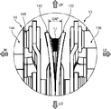
- the vehicle seat 1 includes a left seat back frame 10, a central seat back frame 11, and a right seat back frame 12.
- the left seat back frame 10 is arranged at the left end in the vehicle width direction.
- the right seat back frame 12 is arranged at the right end in the vehicle width direction.
- the central seat back frame 11 is arranged between the left seat back frame 10 and the right seat back frame 12 and is adjacent to both the left seat back frame 10 and the right seat back frame 12.
- the left seat back frame 10 corresponds to the "first seat back frame”
- the central seat back frame 11 corresponds to the "second seat back frame”.
- the left seat back frame 10 is a frame body having a substantially rectangular appearance shape when viewed from the front, and has an upper frame 100, side frames 101 and 102, and a lower frame 103.
- a bracket 107 is provided at a corner portion from the lower portion of the side frame 102 to the lower frame 103.
- a catch portion 104 is provided on the upper portion of the left side frame 101.
- the fork portion 105 is provided for engagement with the striker 501 fixed to the vehicle body.
- the striker 501 has a base 5010 fixed to the vehicle body and a bar 5011 protruding from the base 5010 toward the center side in the vehicle width direction.
- the catch portion 104 has a fork portion 105 that engages with the bar 5011 of the striker 501 when the left seat back frame 10 is in an upright posture as shown by an arrow D.
- a bar 106 extending toward the center is provided on the upper portion of the right side frame 102.
- the bar 106 of the left seat back frame 10 is a portion for engaging with the central seat back frame 11.
- the central seat back frame 11 is also a frame body having a substantially rectangular appearance shape when viewed from the front, and has an upper frame 110, side frames 111, 112, and a lower frame 113. There is. Brackets 117 and 118 are provided at the corners from the lower portions of the side frames 111 and 112 to the lower frame 113.
- a catch portion 114 is provided on the upper portion of the left side frame 111.
- the catch portion 114 is provided for engaging with the bar 106 provided on the left seat back frame 10.
- the right seat back frame 12 is a frame body having a substantially rectangular appearance shape when viewed from the front, and has an upper frame 120, side frames 121 and 122, and a lower frame 123. There is.
- a bracket 127 is provided at a corner portion from the lower portion of the side frame 121 to the lower frame 123.
- a catch portion 124 having the same structure as the catch portion 104 of the left seat back frame 10 is provided on the upper portion of the right side frame 122.
- the fork portion (not shown) of the catch portion 124 can engage with the bar 5021 of the striker 502 fixed to the vehicle body. By engaging the striker 502 and the catch portion 124, the right seat back frame 12 is also held in an upright posture.
- a hinge (left outer hinge) 13 provided at a position between the left seat back frame 10 and the center seat back frame 11 in the vehicle width direction is connected to the bracket 107 of the left seat back frame 10.
- the left seat back frame 10 is rotatably supported by the left outer hinge 13, and the posture can be changed between the forward tilted posture in which the left seat back frame 10 is tilted forward and the standing posture shown in FIG. It has become.
- the left outer hinge 13 corresponds to the "first hinge".
- the hinge (left inner hinge) 14 provided at a position adjacent to the right side of the left outer hinge 13 is connected to the bracket 117 of the central seat back frame 11.
- a hinge (right inner hinge) 15 provided at a position spaced to the right from the left inner hinge 14 is connected to the bracket 118 of the central seat back frame 11.
- the central seat back frame 11 is rotatably supported by the left inner hinge 14 and the right inner hinge 15, and the central seat back frame 11 is tilted forward and the standing posture shown in FIG. The posture can be changed between.
- the left inner hinge 14 corresponds to the "second hinge".
- the hinge (right outer hinge) 16 provided at a position adjacent to the right side of the right inner hinge 15 is connected to the bracket 127 of the right seat back frame 12.
- the right seat back frame 12 is rotatably supported by the right outer hinge 16, and the posture can be changed between the forward tilted posture in which the right seat back frame 12 is tilted forward and the standing posture shown in FIG. It has become.
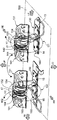
- hinge 13 to 16 The structure of hinge 13 to 16 will be described with reference to FIGS. 4 and 5. Although the left outer hinge 13 and the left inner hinge 14 are shown in FIGS. 4 and 5, the right inner hinge 15 and the right outer hinge 16 have the same structure.
- the left outer hinge 13 has a base bracket 130, a frame bracket 131, a hinge bracket 132, and springs 134 and 135.
- the base bracket 130 has a substantially flat plate shape and is a portion for fixing to the floor panel 500.
- the frame bracket 131 is formed by bending a metal plate and is a portion for joining to the bracket 107 of the left seat back frame 10.
- the hinge bracket 132 is a portion that is continuous with the right end side of the base bracket 130 and is formed so as to stand upward from the right end side of the base bracket 130.
- a rotation shaft 133 is provided so as to project toward the left side on the main surface on the left side of the hinge bracket 132.
- the rotation shaft 133 is a central axis when the left seat back frame 10 joined to the frame bracket 131 rotates.
- the frame bracket 131 is provided with a pin 136 parallel to the rotation shaft 133.
- the springs 134, 135 are provided around the rotation shaft 133, and the winding end is locked to the pin 136.
- the spring 134 is a forward rotation spring that urges the left seat back frame 10 joined to the frame bracket 131 in a direction in which the posture changes from a forward tilted posture to an upright posture.
- the spring 135 is a reversing spring that urges the left seat back frame 10 joined to the frame bracket 131 in a direction in which the posture changes from an upright posture to a forward tilted posture.
- the base bracket 130 and the hinge bracket 132 correspond to the "first fixed part", and the "frame bracket 131" corresponds to the "first movable part”.
- the left inner hinge 14 has a base bracket 140, a frame bracket 141, a hinge bracket 142, and a spring 144.
- the base bracket 140 has a substantially flat plate shape and is a portion for fixing to the floor panel 500.
- the frame bracket 141 is formed by bending a metal plate, and is a portion for joining to the bracket 117 of the central seat back frame 11.
- the hinge bracket 142 is a portion that is continuous with the left end side of the base bracket 140 and is formed so as to stand upward from the left end side of the base bracket 140.
- a rotation shaft 143 is provided so as to project toward the right side on the main surface on the right side of the hinge bracket 142.
- the rotation shaft 143 is provided so that the rotation shaft 133 and the shaft core coincide with each other, and is a central shaft when the central seat back frame 11 joined to the frame bracket 141 rotates.
- the frame bracket 141 is provided with a pin 146 parallel to the rotation shaft 143.
- the spring 144 is provided around the rotation shaft 143 and the winding end is locked to the pin 146.
- the spring 144 is a forward rotation spring that urges the central seat back frame 11 joined to the frame bracket 141 in a direction in which the posture changes from a forward tilted posture to an upright posture.
- the base bracket 140 and the hinge bracket 142 correspond to the "second fixed part", and the frame bracket 141 corresponds to the "second movable part”.
- the hinge bracket 132 of the left outer hinge 13 and the hinge bracket 142 of the left inner hinge 14 are joined by a welded portion 17 formed in the vicinity of the upper end.
- the left outer hinge 13 and the left inner hinge 14 are joined to the hinge bracket 132 and the hinge bracket 142 at a position above the floor panel 500.
- the welded portion 17 in this embodiment corresponds to a “joint portion”.
- the right inner hinge 15 has a symmetrical structure with respect to the left inner hinge 14, and the right outer hinge 16 has a symmetrical structure with respect to the left outer hinge 13.
- the hinge brackets of the right inner hinge 15 and the right outer hinge 16 are also joined by the welded portion 17.
- the weld 17 is formed to join between the upper end of the hinge bracket 132 of the left outer hinge 13 and the upper end of the hinge bracket 142 of the left inner hinge 14. .
- the hinge bracket 132 of the left outer hinge 13 and the hinge bracket 142 of the left inner hinge 14 are viewed from the front, the hinge bracket 132 of the left outer hinge 13 and the hinge bracket 142 of the left inner hinge 14 are used. Is formed so that the gap GAPs of each other gradually expand as they go from the bottom to the top.
- the welded portion formed between the hinge bracket of the right inner hinge 15 and the hinge bracket of the right outer hinge 16 has the same configuration.
- FIGS. 8 and 9 show a vehicle seat 9 according to a comparative example.
- the difference between the vehicle seat 9 according to the comparative example and the vehicle seat 1 according to the present embodiment is that the hinge brackets of the hinges 93 and 94 and the hinge brackets of the hinges 95 and 96 are not joined to each other.
- the left seat back frame 90 in the forward tilted posture is erected.
- the left seat back frame 90 is twisted as shown by the arrows K1 and L1 due to the strong urging force of the reversing spring (spring provided in the J1 portion) provided on the hinge 93. Therefore, a large force is required to engage the catch portion 904 of the left seat back frame 90 with the bar 5011 of the striker 501.
- a similar twist occurs when the left seat back frame 90 and the central seat back frame 91 are to be erected while the bar 906 and the catch portion 914 of the central seat back frame 91 are engaged with each other.
- the right seat back frame 92 when trying to stand up from the forward tilted posture, the right seat is also affected by the strong urging force of the reversing spring (spring provided in the J2 portion) provided on the hinge 96.
- the back frame 92 is twisted as shown by the arrows K2 and L2. Therefore, a large force is required to engage the catch portion 924 of the right seat back frame 92 with the bar 5021 of the striker 502.
- the hinge brackets 132 and 142 of the hinges 13 and 14 adjacent to each other in the vehicle width direction are joined to each other by the welded portion 17 (G1 portion). Therefore, when the left seat back frame 10 in the forward tilted posture is to be erected, the urging force of the reversing spring 135 is distributed from the hinge bracket 132 to the hinge bracket 142 via the welded portion 17. Therefore, the base bracket 130 of the hinge 13 and the base bracket 140 of the hinge 14 can suppress the twist as shown by the arrow H1 in the left seat back frame 10 when trying to stand up from the forward leaning posture.
- the hinge brackets 152 and 162 of the hinges 15 and 16 adjacent to each other in the vehicle width direction are also joined by the welded portion 17 (G2 portion). Therefore, even when the right seat back frame 12 in the forward tilted posture is to be erected, the urging force of the reversing spring 164 is distributed from the hinge bracket 162 to the hinge bracket 152 via the welded portion 17. Therefore, the base bracket 160 of the hinge 16 and the base bracket 150 of the hinge 15 can suppress the twist as shown by the arrow H2 in the right seat back frame 12 when trying to stand up from the forward leaning posture.
- the hinge bracket 132 and the hinge bracket 142 are joined, and the hinge bracket 152 and the hinge bracket 162 are joined by welding the portions above the rotation shafts 133 and 143. Since it is done by doing so, it is possible to effectively suppress the twisting of the seat back frames 10 and 12. That is, when the seat back frames 10 and 12 are erected from the forward tilted posture, twisting occurs from the rotation shafts 133 and 143, which are the centers of rotation, and therefore, the seats are twisted above the rotation shafts 133 and 143. By joining the hinge brackets to each other at the above points, twisting from the upper part of the hinge can be reliably suppressed.
- the seat back in the forward tilted posture (the seat back including the seat back frame 10 and the seat back frame 12 in the configuration) is erected to support the catch portions 104 and 124.
- the strikers 501 and 502 no large force is required for the engagement.
- the hinge bracket 132 and the hinge bracket 142, and the hinge bracket 152 and the hinge bracket 162 are joined by the welded portion 17, but the method of joining the hinge brackets is limited to this. It's not a thing. For example, it may be joined by screwing with a bolt or the like.
- the upper ends of the hinge bracket 132 and the hinge bracket 142 are joined to each other, and the upper ends of the hinge bracket 152 and the hinge bracket 162 are joined to each other. I don't receive it. It is possible to join the intermediate portions of the hinge brackets in the height direction to each other, or to join the upper ends to each other and the intermediate portions to each other.
- the vehicle seat 1 a structure in which three seat back frames 10 to 12 are arranged side by side in the vehicle width direction is adopted, but in the present invention, two seat back frames are arranged side by side in the vehicle width direction. It is also possible to adopt a vehicle seat having a structure provided.
- the vehicle seat 1 as the rear seat of the automobile is taken as an example, but in the present invention, the vehicle seat as the front seat can also be adopted.
- the coil spring is adopted as the reversing spring 135, 154, 164, but the present invention is not limited to this.
- the vehicle seat according to one aspect of the present invention is a vehicle seat fixed to the floor panel of the vehicle body, is arranged on one end side in the vehicle width direction, and changes the posture between the forward tilted posture and the standing posture.
- An engaged portion provided on one end side and capable of engaging with an engaging portion provided on the vehicle body, and a boundary portion between the first seat back frame and the second seat back frame in the vehicle width direction or
- a first fixed portion arranged in the vicinity thereof and fixed to the floor panel and a first movable portion to which the lower portion of the first seat back frame is joined and rotatable with respect to the first fixed portion are provided.
- the first hinge to be held, the second fixing portion arranged at a position adjacent to the inside of the vehicle width direction with respect to the first hinge and fixed to the floor panel, and the lower part of the second seat back frame are joined.
- a second hinge having a second movable portion that is rotatable with respect to the second fixed portion, and a posture of the first seat back frame attached to the first hinge are tilted forward from the standing posture.
- a joint portion for joining the first fixing portion of the hinge and the second fixing portion of the second hinge is provided.
- the first fixing of the first hinge is performed at a position above the fixing point with the floor panel at each of the first hinge and the second hinge (a place different from the fixing point of the floor panel). Since it is provided with a joint that joins the part and the second fixing part of the second hinge, it is urged when the seat back including the first seat back frame is to stand up from the forward tilted posture and engage with the vehicle body. The urging force of the member can be distributed to the second hinge. Therefore, in the vehicle seat according to the above aspect, it is possible to suppress the twisting of the first seat back frame when the seat back including the first seat back frame is to be erected, and the engaged portion can be formed. It does not require a large force to engage the engaging part.
- the first fixing portion of the first hinge and the second fixing portion of the second hinge are joined to transfer the urging force by the urging member from the first hinge to the second hinge. Since it can be dispersed, the bending of the fixed portion of the first hinge with the floor panel can be suppressed to a small extent.
- the first hinge abuts on the floor panel and is continuous with the first base bracket and the first base bracket fixed to the floor panel, and the first base bracket is connected to the first base bracket.
- the second hinge has a first hinge bracket provided so as to stand up from the end side of the floor panel, and the second hinge abuts on the floor panel and is fixed to the floor panel. It has a second hinge bracket that is continuous with the base bracket and is provided so as to stand up from the end side of the second base bracket, and the first fixing portion is the first hinge bracket and the second.
- the fixing portion may be the second hinge bracket.
- the seat back including the first seat back frame is provided.
- the urging force applied by the urging member when trying to stand up from the forward tilted posture can be distributed to the second hinge bracket. Therefore, it is possible to suppress the twisting of the first seat back frame when the seat back including the first seat back frame is to be erected from the forward tilted posture.
- the first hinge further has a rotation shaft which is a central axis related to the rotation of the first seat back frame to which the base end is joined to the first hinge bracket.
- the joint may be provided at a position above the base end of the rotation shaft in the first hinge bracket.
- the seat back including the first seat back frame is to be erected from the forward tilted posture by providing the joint portion at a position above the base end of the rotation shaft in the first hinge bracket.
- the urging force can be distributed to the second hinge at a position above the center of rotation of the first seat back frame. Therefore, when the above configuration is adopted, it is possible to suppress the twisting of the first seat back frame when the seat back including the first seat back frame is to stand up from the forward leaning posture, and the engagement can be suppressed. Does not require much power for.
- the first hinge is provided so as to be rotatable about the rotation shaft, and further has a frame bracket to which the first seat back frame is joined, and the urging member. May be a coil spring provided around the rotation axis and having an action point on the frame bracket.
- the joint portion is connected to the rotation shaft which is the winding center of the coil spring.
- the urging force of the coil spring can be effectively distributed to the second hinge. Therefore, when the above configuration is adopted, it is possible to suppress the twisting of the first seat back frame when the seat back including the first seat back frame is to stand up from the forward leaning posture, and the engagement can be suppressed. Does not require much power for.
- the joint portion may be provided so as to join the upper end portions of the first hinge bracket and the second hinge bracket to each other.
- the joint portion is formed from the rotation shaft in the radial direction related to the rotation of the first seat back frame. You can take the maximum distance to. Therefore, the urging force of the coil spring can be effectively distributed to the second hinge without increasing the joint strength between the first hinge bracket and the second hinge bracket by the joint portion. Therefore, when the above configuration is adopted, it is possible to suppress the twisting of the first seat back frame when the seat back including the first seat back frame is to stand up from the forward leaning posture, and the engagement can be suppressed. Does not require much power for.
- the gap between the upper end portions of the first hinge bracket and the second hinge bracket is lower than the upper end portion.
- the joint portion may be provided so as to be wider than the gap between the portions, and the joint portion may be a welded portion formed by welding the upper end portions of the first hinge bracket and the second hinge bracket to each other. ..
- the joint portion is a welded portion, and the gap between the first hinge bracket and the second hinge bracket is widened at the upper end portion rather than the lower portion, so that workability at the time of welding is improved.
- the foldable seat back arranged on the end side in the vehicle width direction is erected from the forward tilted posture and engaged with the vehicle body, the said person concerned. Does not require a large force for engagement.
Landscapes
- Engineering & Computer Science (AREA)
- Aviation & Aerospace Engineering (AREA)
- Transportation (AREA)
- Mechanical Engineering (AREA)
- Seats For Vehicles (AREA)
Abstract
Priority Applications (3)
| Application Number | Priority Date | Filing Date | Title |
|---|---|---|---|
| US17/996,268 US12351085B2 (en) | 2020-07-10 | 2021-06-23 | Vehicle seat |
| CN202180030703.7A CN115443228B (zh) | 2020-07-10 | 2021-06-23 | 交通工具用座椅 |
| EP21836998.1A EP4116143B1 (fr) | 2020-07-10 | 2021-06-23 | Siège de véhicule |
Applications Claiming Priority (2)
| Application Number | Priority Date | Filing Date | Title |
|---|---|---|---|
| JP2020119433A JP7477868B2 (ja) | 2020-07-10 | 2020-07-10 | 乗物用シート |
| JP2020-119433 | 2020-07-10 |
Publications (1)
| Publication Number | Publication Date |
|---|---|
| WO2022009673A1 true WO2022009673A1 (fr) | 2022-01-13 |
Family
ID=79552916
Family Applications (1)
| Application Number | Title | Priority Date | Filing Date |
|---|---|---|---|
| PCT/JP2021/023696 Ceased WO2022009673A1 (fr) | 2020-07-10 | 2021-06-23 | Siège de véhicule |
Country Status (5)
| Country | Link |
|---|---|
| US (1) | US12351085B2 (fr) |
| EP (1) | EP4116143B1 (fr) |
| JP (1) | JP7477868B2 (fr) |
| CN (1) | CN115443228B (fr) |
| WO (1) | WO2022009673A1 (fr) |
Families Citing this family (1)
| Publication number | Priority date | Publication date | Assignee | Title |
|---|---|---|---|---|
| JP7477868B2 (ja) * | 2020-07-10 | 2024-05-02 | デルタ工業株式会社 | 乗物用シート |
Citations (4)
| Publication number | Priority date | Publication date | Assignee | Title |
|---|---|---|---|---|
| JPH0193144U (fr) * | 1987-12-14 | 1989-06-19 | ||
| JPH09150657A (ja) * | 1995-11-30 | 1997-06-10 | Delta Kogyo Co Ltd | 自動車用シートクッションのロック構造 |
| JP2016150733A (ja) | 2015-02-19 | 2016-08-22 | 日本発條株式会社 | 車両用リヤシート |
| JP6191373B2 (ja) | 2013-10-07 | 2017-09-06 | スズキ株式会社 | シートバック連結構造 |
Family Cites Families (17)
| Publication number | Priority date | Publication date | Assignee | Title |
|---|---|---|---|---|
| DE3316024C2 (de) * | 1983-05-03 | 1986-09-04 | Adam Opel AG, 6090 Rüsselsheim | Schwenkbare Rückenlehne, insbesondere von Sitzbänken in Kraftfahrzeugen |
| US4958877A (en) * | 1989-08-01 | 1990-09-25 | Chrysler Corporation | Composite pivot bushing and cover for vehicle seat hinge bracket |
| JPH0729008Y2 (ja) * | 1991-07-29 | 1995-07-05 | 池田物産株式会社 | 車両用シート |
| JP2540276Y2 (ja) * | 1991-11-19 | 1997-07-02 | 三菱自動車工業株式会社 | 分割シートバックのセンターヒンジ構造 |
| US5685612A (en) * | 1996-06-04 | 1997-11-11 | Lear Corporation | Seat center pivot bracket assembly |
| DE102005029649A1 (de) | 2005-06-23 | 2006-12-28 | Johnson Controls Gmbh | Lager für die umklappbare Rückenlehne eines Fahrzeugsitzes |
| JP4595859B2 (ja) | 2006-03-27 | 2010-12-08 | トヨタ紡織株式会社 | 車両用シートのシートバックロック装置 |
| JP4984679B2 (ja) | 2006-06-28 | 2012-07-25 | スズキ株式会社 | 分割可倒式シートバックのセンターヒンジ構造 |
| JP2008265523A (ja) * | 2007-04-20 | 2008-11-06 | Suzuki Motor Corp | 車両用シートの分割式シートバック取付構造 |
| JP5126481B2 (ja) * | 2007-04-20 | 2013-01-23 | スズキ株式会社 | 分割式シートバックの開き防止構造 |
| US7748766B2 (en) | 2008-03-27 | 2010-07-06 | Gm Global Technology Operations, Inc. | Vehicle seat assembly and method for use thereof |
| JP2011073621A (ja) | 2009-09-30 | 2011-04-14 | Mazda Motor Corp | 折り畳みシート装置 |
| JP5666284B2 (ja) * | 2010-12-20 | 2015-02-12 | テイ・エス テック株式会社 | 車両の折り畳み式シート装置 |
| EP2634039A1 (fr) * | 2012-02-29 | 2013-09-04 | Fiat Group Automobiles S.p.A. | Siège arrière de véhicule automobile |
| DE102015212547B4 (de) * | 2015-07-06 | 2020-01-09 | Lear Corporation | Sitzanordnung mit Schwenkmechanismus |
| GB2567425B (en) | 2017-10-06 | 2020-08-19 | Jaguar Land Rover Ltd | A moveable vehicle seat assembly |
| JP7477868B2 (ja) * | 2020-07-10 | 2024-05-02 | デルタ工業株式会社 | 乗物用シート |
-
2020
- 2020-07-10 JP JP2020119433A patent/JP7477868B2/ja active Active
-
2021
- 2021-06-23 WO PCT/JP2021/023696 patent/WO2022009673A1/fr not_active Ceased
- 2021-06-23 EP EP21836998.1A patent/EP4116143B1/fr active Active
- 2021-06-23 US US17/996,268 patent/US12351085B2/en active Active
- 2021-06-23 CN CN202180030703.7A patent/CN115443228B/zh active Active
Patent Citations (4)
| Publication number | Priority date | Publication date | Assignee | Title |
|---|---|---|---|---|
| JPH0193144U (fr) * | 1987-12-14 | 1989-06-19 | ||
| JPH09150657A (ja) * | 1995-11-30 | 1997-06-10 | Delta Kogyo Co Ltd | 自動車用シートクッションのロック構造 |
| JP6191373B2 (ja) | 2013-10-07 | 2017-09-06 | スズキ株式会社 | シートバック連結構造 |
| JP2016150733A (ja) | 2015-02-19 | 2016-08-22 | 日本発條株式会社 | 車両用リヤシート |
Also Published As
| Publication number | Publication date |
|---|---|
| CN115443228B (zh) | 2023-10-20 |
| US12351085B2 (en) | 2025-07-08 |
| US20230202356A1 (en) | 2023-06-29 |
| EP4116143B1 (fr) | 2026-01-07 |
| JP2022016130A (ja) | 2022-01-21 |
| EP4116143A4 (fr) | 2023-09-13 |
| CN115443228A (zh) | 2022-12-06 |
| JP7477868B2 (ja) | 2024-05-02 |
| EP4116143A1 (fr) | 2023-01-11 |
Similar Documents
| Publication | Publication Date | Title |
|---|---|---|
| JP5339774B2 (ja) | 車両用シートバックのフレーム構造及び該構造を有する車両用シートバック | |
| CN102574484B (zh) | 车辆用座椅 | |
| JP4033696B2 (ja) | 車両用シート装置 | |
| JP5358646B2 (ja) | 車両用シート | |
| JP5691769B2 (ja) | 車両用シートのバックフレーム | |
| JP2006051272A (ja) | シートバックフレーム構造 | |
| JP5526718B2 (ja) | 車両用シート装置 | |
| WO2022009673A1 (fr) | Siège de véhicule | |
| JP2010051502A (ja) | 車両用シート | |
| JP2013212766A (ja) | 車両用シート装置 | |
| JP2002104039A (ja) | 跳ね上げシート | |
| JP7103166B2 (ja) | 車両用シート | |
| US10040384B2 (en) | Twist-lock articulating assist mechanism | |
| JP5339790B2 (ja) | パネルタイプの車両用シートバックのフレーム構造及び該構造を有する車両用シートバック | |
| JP4477558B2 (ja) | シート | |
| JP2016132286A (ja) | 乗物用シートのテーブル装置 | |
| JP7196737B2 (ja) | 乗物用シートヒンジ機構 | |
| JP2009201663A (ja) | 車両用シートリクライニング装置 | |
| JP2019151197A (ja) | 車両用シート構造 | |
| JP2006021725A (ja) | 車両用シートのフレーム構造 | |
| US20250153616A1 (en) | Stowable vehicle seat | |
| JP7352836B2 (ja) | シートフレーム | |
| JP2854253B2 (ja) | 車両用多目的シート | |
| JP2023050069A (ja) | 乗物用シート | |
| JP6841093B2 (ja) | 乗物用シート |
Legal Events
| Date | Code | Title | Description |
|---|---|---|---|
| 121 | Ep: the epo has been informed by wipo that ep was designated in this application |
Ref document number: 21836998 Country of ref document: EP Kind code of ref document: A1 |
|
| ENP | Entry into the national phase |
Ref document number: 2021836998 Country of ref document: EP Effective date: 20221005 |
|
| NENP | Non-entry into the national phase |
Ref country code: DE |
|
| WWG | Wipo information: grant in national office |
Ref document number: 17996268 Country of ref document: US |
|
| WWG | Wipo information: grant in national office |
Ref document number: 2021836998 Country of ref document: EP |