WO2022019198A1 - グリースの原料、グリースの原料の製造方法、グリースの製造方法、および、グリース - Google Patents
グリースの原料、グリースの原料の製造方法、グリースの製造方法、および、グリース Download PDFInfo
- Publication number
- WO2022019198A1 WO2022019198A1 PCT/JP2021/026499 JP2021026499W WO2022019198A1 WO 2022019198 A1 WO2022019198 A1 WO 2022019198A1 JP 2021026499 W JP2021026499 W JP 2021026499W WO 2022019198 A1 WO2022019198 A1 WO 2022019198A1
- Authority
- WO
- WIPO (PCT)
- Prior art keywords
- grease
- raw material
- solvent
- thickener
- lubricating oil
- Prior art date
- Legal status (The legal status is an assumption and is not a legal conclusion. Google has not performed a legal analysis and makes no representation as to the accuracy of the status listed.)
- Ceased
Links
Images


Classifications
-
- C—CHEMISTRY; METALLURGY
- C10—PETROLEUM, GAS OR COKE INDUSTRIES; TECHNICAL GASES CONTAINING CARBON MONOXIDE; FUELS; LUBRICANTS; PEAT
- C10M—LUBRICATING COMPOSITIONS; USE OF CHEMICAL SUBSTANCES EITHER ALONE OR AS LUBRICATING INGREDIENTS IN A LUBRICATING COMPOSITION
- C10M177/00—Special methods of preparation of lubricating compositions; Chemical modification by after-treatment of components or of the whole of a lubricating composition, not covered by other classes
-
- C—CHEMISTRY; METALLURGY
- C10—PETROLEUM, GAS OR COKE INDUSTRIES; TECHNICAL GASES CONTAINING CARBON MONOXIDE; FUELS; LUBRICANTS; PEAT
- C10M—LUBRICATING COMPOSITIONS; USE OF CHEMICAL SUBSTANCES EITHER ALONE OR AS LUBRICATING INGREDIENTS IN A LUBRICATING COMPOSITION
- C10M105/00—Lubricating compositions characterised by the base-material being a non-macromolecular organic compound
- C10M105/08—Lubricating compositions characterised by the base-material being a non-macromolecular organic compound containing oxygen
- C10M105/32—Esters
- C10M105/36—Esters of polycarboxylic acids
-
- C—CHEMISTRY; METALLURGY
- C10—PETROLEUM, GAS OR COKE INDUSTRIES; TECHNICAL GASES CONTAINING CARBON MONOXIDE; FUELS; LUBRICANTS; PEAT
- C10M—LUBRICATING COMPOSITIONS; USE OF CHEMICAL SUBSTANCES EITHER ALONE OR AS LUBRICATING INGREDIENTS IN A LUBRICATING COMPOSITION
- C10M107/00—Lubricating compositions characterised by the base-material being a macromolecular compound
- C10M107/02—Hydrocarbon polymers; Hydrocarbon polymers modified by oxidation
- C10M107/18—Hydrocarbon polymers modified by oxidation
-
- C—CHEMISTRY; METALLURGY
- C10—PETROLEUM, GAS OR COKE INDUSTRIES; TECHNICAL GASES CONTAINING CARBON MONOXIDE; FUELS; LUBRICANTS; PEAT
- C10M—LUBRICATING COMPOSITIONS; USE OF CHEMICAL SUBSTANCES EITHER ALONE OR AS LUBRICATING INGREDIENTS IN A LUBRICATING COMPOSITION
- C10M115/00—Lubricating compositions characterised by the thickener being a non-macromolecular organic compound other than a carboxylic acid or salt thereof
- C10M115/08—Lubricating compositions characterised by the thickener being a non-macromolecular organic compound other than a carboxylic acid or salt thereof containing nitrogen
-
- C—CHEMISTRY; METALLURGY
- C10—PETROLEUM, GAS OR COKE INDUSTRIES; TECHNICAL GASES CONTAINING CARBON MONOXIDE; FUELS; LUBRICANTS; PEAT
- C10M—LUBRICATING COMPOSITIONS; USE OF CHEMICAL SUBSTANCES EITHER ALONE OR AS LUBRICATING INGREDIENTS IN A LUBRICATING COMPOSITION
- C10M169/00—Lubricating compositions characterised by containing as components a mixture of at least two types of ingredient selected from base-materials, thickeners or additives, covered by the preceding groups, each of these compounds being essential
- C10M169/02—Mixtures of base-materials and thickeners
-
- C—CHEMISTRY; METALLURGY
- C10—PETROLEUM, GAS OR COKE INDUSTRIES; TECHNICAL GASES CONTAINING CARBON MONOXIDE; FUELS; LUBRICANTS; PEAT
- C10M—LUBRICATING COMPOSITIONS; USE OF CHEMICAL SUBSTANCES EITHER ALONE OR AS LUBRICATING INGREDIENTS IN A LUBRICATING COMPOSITION
- C10M2203/00—Organic non-macromolecular hydrocarbon compounds and hydrocarbon fractions as ingredients in lubricant compositions
- C10M2203/06—Well-defined aromatic compounds
- C10M2203/065—Well-defined aromatic compounds used as base material
-
- C—CHEMISTRY; METALLURGY
- C10—PETROLEUM, GAS OR COKE INDUSTRIES; TECHNICAL GASES CONTAINING CARBON MONOXIDE; FUELS; LUBRICANTS; PEAT
- C10M—LUBRICATING COMPOSITIONS; USE OF CHEMICAL SUBSTANCES EITHER ALONE OR AS LUBRICATING INGREDIENTS IN A LUBRICATING COMPOSITION
- C10M2203/00—Organic non-macromolecular hydrocarbon compounds and hydrocarbon fractions as ingredients in lubricant compositions
- C10M2203/10—Petroleum or coal fractions, e.g. tars, solvents, bitumen
- C10M2203/1006—Petroleum or coal fractions, e.g. tars, solvents, bitumen used as base material
-
- C—CHEMISTRY; METALLURGY
- C10—PETROLEUM, GAS OR COKE INDUSTRIES; TECHNICAL GASES CONTAINING CARBON MONOXIDE; FUELS; LUBRICANTS; PEAT
- C10M—LUBRICATING COMPOSITIONS; USE OF CHEMICAL SUBSTANCES EITHER ALONE OR AS LUBRICATING INGREDIENTS IN A LUBRICATING COMPOSITION
- C10M2205/00—Organic macromolecular hydrocarbon compounds or fractions, whether or not modified by oxidation as ingredients in lubricant compositions
- C10M2205/02—Organic macromolecular hydrocarbon compounds or fractions, whether or not modified by oxidation as ingredients in lubricant compositions containing acyclic monomers
- C10M2205/0206—Organic macromolecular hydrocarbon compounds or fractions, whether or not modified by oxidation as ingredients in lubricant compositions containing acyclic monomers used as base material
-
- C—CHEMISTRY; METALLURGY
- C10—PETROLEUM, GAS OR COKE INDUSTRIES; TECHNICAL GASES CONTAINING CARBON MONOXIDE; FUELS; LUBRICANTS; PEAT
- C10M—LUBRICATING COMPOSITIONS; USE OF CHEMICAL SUBSTANCES EITHER ALONE OR AS LUBRICATING INGREDIENTS IN A LUBRICATING COMPOSITION
- C10M2205/00—Organic macromolecular hydrocarbon compounds or fractions, whether or not modified by oxidation as ingredients in lubricant compositions
- C10M2205/02—Organic macromolecular hydrocarbon compounds or fractions, whether or not modified by oxidation as ingredients in lubricant compositions containing acyclic monomers
- C10M2205/028—Organic macromolecular hydrocarbon compounds or fractions, whether or not modified by oxidation as ingredients in lubricant compositions containing acyclic monomers containing aliphatic monomers having more than four carbon atoms
- C10M2205/0285—Organic macromolecular hydrocarbon compounds or fractions, whether or not modified by oxidation as ingredients in lubricant compositions containing acyclic monomers containing aliphatic monomers having more than four carbon atoms used as base material
-
- C—CHEMISTRY; METALLURGY
- C10—PETROLEUM, GAS OR COKE INDUSTRIES; TECHNICAL GASES CONTAINING CARBON MONOXIDE; FUELS; LUBRICANTS; PEAT
- C10M—LUBRICATING COMPOSITIONS; USE OF CHEMICAL SUBSTANCES EITHER ALONE OR AS LUBRICATING INGREDIENTS IN A LUBRICATING COMPOSITION
- C10M2207/00—Organic non-macromolecular hydrocarbon compounds containing hydrogen, carbon and oxygen as ingredients in lubricant compositions
- C10M2207/28—Esters
- C10M2207/285—Esters of aromatic polycarboxylic acids
- C10M2207/2855—Esters of aromatic polycarboxylic acids used as base material
-
- C—CHEMISTRY; METALLURGY
- C10—PETROLEUM, GAS OR COKE INDUSTRIES; TECHNICAL GASES CONTAINING CARBON MONOXIDE; FUELS; LUBRICANTS; PEAT
- C10M—LUBRICATING COMPOSITIONS; USE OF CHEMICAL SUBSTANCES EITHER ALONE OR AS LUBRICATING INGREDIENTS IN A LUBRICATING COMPOSITION
- C10M2209/00—Organic macromolecular compounds containing oxygen as ingredients in lubricant compositions
- C10M2209/10—Macromolecular compoundss obtained otherwise than by reactions only involving carbon-to-carbon unsaturated bonds
- C10M2209/103—Polyethers, i.e. containing di- or higher polyoxyalkylene groups
- C10M2209/1033—Polyethers, i.e. containing di- or higher polyoxyalkylene groups used as base material
-
- C—CHEMISTRY; METALLURGY
- C10—PETROLEUM, GAS OR COKE INDUSTRIES; TECHNICAL GASES CONTAINING CARBON MONOXIDE; FUELS; LUBRICANTS; PEAT
- C10M—LUBRICATING COMPOSITIONS; USE OF CHEMICAL SUBSTANCES EITHER ALONE OR AS LUBRICATING INGREDIENTS IN A LUBRICATING COMPOSITION
- C10M2215/00—Organic non-macromolecular compounds containing nitrogen as ingredients in lubricant Compositions
- C10M2215/10—Amides of carbonic or haloformic acids
- C10M2215/102—Ureas; Semicarbazides; Allophanates
- C10M2215/1026—Ureas; Semicarbazides; Allophanates used as thickening material
-
- C—CHEMISTRY; METALLURGY
- C10—PETROLEUM, GAS OR COKE INDUSTRIES; TECHNICAL GASES CONTAINING CARBON MONOXIDE; FUELS; LUBRICANTS; PEAT
- C10M—LUBRICATING COMPOSITIONS; USE OF CHEMICAL SUBSTANCES EITHER ALONE OR AS LUBRICATING INGREDIENTS IN A LUBRICATING COMPOSITION
- C10M2290/00—Mixtures of base materials or thickeners or additives
- C10M2290/04—Synthetic base oils
-
- C—CHEMISTRY; METALLURGY
- C10—PETROLEUM, GAS OR COKE INDUSTRIES; TECHNICAL GASES CONTAINING CARBON MONOXIDE; FUELS; LUBRICANTS; PEAT
- C10M—LUBRICATING COMPOSITIONS; USE OF CHEMICAL SUBSTANCES EITHER ALONE OR AS LUBRICATING INGREDIENTS IN A LUBRICATING COMPOSITION
- C10M2290/00—Mixtures of base materials or thickeners or additives
- C10M2290/10—Thickener
-
- C—CHEMISTRY; METALLURGY
- C10—PETROLEUM, GAS OR COKE INDUSTRIES; TECHNICAL GASES CONTAINING CARBON MONOXIDE; FUELS; LUBRICANTS; PEAT
- C10N—INDEXING SCHEME ASSOCIATED WITH SUBCLASS C10M RELATING TO LUBRICATING COMPOSITIONS
- C10N2020/00—Specified physical or chemical properties or characteristics, i.e. function, of component of lubricating compositions
- C10N2020/01—Physico-chemical properties
- C10N2020/055—Particles related characteristics
- C10N2020/06—Particles of special shape or size
-
- C—CHEMISTRY; METALLURGY
- C10—PETROLEUM, GAS OR COKE INDUSTRIES; TECHNICAL GASES CONTAINING CARBON MONOXIDE; FUELS; LUBRICANTS; PEAT
- C10N—INDEXING SCHEME ASSOCIATED WITH SUBCLASS C10M RELATING TO LUBRICATING COMPOSITIONS
- C10N2030/00—Specified physical or chemical properties which is improved by the additive characterising the lubricating composition, e.g. multifunctional additives
- C10N2030/06—Oiliness; Film-strength; Anti-wear; Resistance to extreme pressure
-
- C—CHEMISTRY; METALLURGY
- C10—PETROLEUM, GAS OR COKE INDUSTRIES; TECHNICAL GASES CONTAINING CARBON MONOXIDE; FUELS; LUBRICANTS; PEAT
- C10N—INDEXING SCHEME ASSOCIATED WITH SUBCLASS C10M RELATING TO LUBRICATING COMPOSITIONS
- C10N2030/00—Specified physical or chemical properties which is improved by the additive characterising the lubricating composition, e.g. multifunctional additives
- C10N2030/08—Resistance to extreme temperature
-
- C—CHEMISTRY; METALLURGY
- C10—PETROLEUM, GAS OR COKE INDUSTRIES; TECHNICAL GASES CONTAINING CARBON MONOXIDE; FUELS; LUBRICANTS; PEAT
- C10N—INDEXING SCHEME ASSOCIATED WITH SUBCLASS C10M RELATING TO LUBRICATING COMPOSITIONS
- C10N2040/00—Specified use or application for which the lubricating composition is intended
- C10N2040/02—Bearings
-
- C—CHEMISTRY; METALLURGY
- C10—PETROLEUM, GAS OR COKE INDUSTRIES; TECHNICAL GASES CONTAINING CARBON MONOXIDE; FUELS; LUBRICANTS; PEAT
- C10N—INDEXING SCHEME ASSOCIATED WITH SUBCLASS C10M RELATING TO LUBRICATING COMPOSITIONS
- C10N2040/00—Specified use or application for which the lubricating composition is intended
- C10N2040/04—Oil-bath; Gear-boxes; Automatic transmissions; Traction drives
-
- C—CHEMISTRY; METALLURGY
- C10—PETROLEUM, GAS OR COKE INDUSTRIES; TECHNICAL GASES CONTAINING CARBON MONOXIDE; FUELS; LUBRICANTS; PEAT
- C10N—INDEXING SCHEME ASSOCIATED WITH SUBCLASS C10M RELATING TO LUBRICATING COMPOSITIONS
- C10N2050/00—Form in which the lubricant is applied to the material being lubricated
- C10N2050/10—Form in which the lubricant is applied to the material being lubricated semi-solid; greasy
-
- C—CHEMISTRY; METALLURGY
- C10—PETROLEUM, GAS OR COKE INDUSTRIES; TECHNICAL GASES CONTAINING CARBON MONOXIDE; FUELS; LUBRICANTS; PEAT
- C10N—INDEXING SCHEME ASSOCIATED WITH SUBCLASS C10M RELATING TO LUBRICATING COMPOSITIONS
- C10N2070/00—Specific manufacturing methods for lubricant compositions
Definitions
- the present disclosure relates to a raw material for grease, a method for producing a raw material for grease, a method for producing grease, and grease.
- This application claims priority based on Japanese Application No. 2020-125473 filed on July 22, 2020, and incorporates all the contents described in the above Japanese application.
- an amine compound and an isocyanate compound are usually reacted in a base oil to synthesize a urea compound as a thickener in the base oil, and then shearing or the like is applied to form thickener particles.
- Patent Document 1 disclose (poly) urea powder that can be used for urea-based grease and a method for producing the same.
- One aspect of the disclosure is The first thickener raw material and The second thickener raw material and The first lubricant and The second lubricant and A first solvent having a lower boiling point than the first lubricating oil and the second lubricating oil, which dissolves the first lubricating oil and does not dissolve the produced thickener.
- a second solvent having a lower boiling point than the first lubricating oil and the second lubricating oil, which dissolves the second lubricating oil and does not dissolve the generated thickener, is prepared.
- the first lubricating oil is dissolved in the first solvent, and the first thickener raw material is dissolved or dispersed to prepare a first mixed solution.
- the second lubricating oil is dissolved in the second solvent, and the second thickener raw material is dissolved or dispersed to prepare a second mixed solution.
- the first mixed solution and the second mixed solution are mixed, and the first thickener raw material and the second thickener raw material are reacted to produce a thickener. This is a method for manufacturing a raw material for grease.
- Another aspect of the present disclosure is The first thickener raw material and The second thickener raw material and The first lubricant and A first solvent having a boiling point lower than that of the first lubricating oil, which dissolves the first lubricating oil and does not dissolve the produced thickener, A second solvent, which has a boiling point lower than that of the first lubricating oil and does not dissolve the produced thickener, is prepared.
- the first lubricating oil is dissolved in the first solvent, and the first thickener raw material is dissolved or dispersed to prepare a first mixed solution.
- the second thickener raw material is dissolved or dispersed in the second solvent to prepare a second mixed solution.
- the first mixed liquid and the second mixed liquid are mixed, and the first thickener raw material and the second thickener raw material are reacted to produce a thickener.
- the present disclosure includes, as yet another embodiment, a raw material for grease, a method for producing a raw material for other grease, a method for producing grease, and grease.
- FIG. 1 is a cross-sectional view taken along the line AA of FIG. It is BB sectional view of FIG. It is a block diagram which shows typically an example of the column type electric power steering apparatus which filled with the grease which concerns on this disclosure.
- FIG. 4 is a cross-sectional view taken along the line AA of FIG. It is sectional drawing of the rolling bearing which filled with the grease which concerns on this disclosure. It is a process drawing for demonstrating the manufacturing method of the raw material of the grease of 1st Embodiment. It is a process drawing for demonstrating the manufacturing method of the raw material of the grease of 2nd Embodiment.
- the powdery urea compound synthesized in a solvent and from which the solvent has been removed can be used as a thickener and can be mixed with a base oil to produce a grease.
- unreacted amine compounds and isocyanate compounds can be removed by a washing treatment before mixing with the base oil. Therefore, it is possible to prevent unreacted amine compounds and isocyanate compounds from remaining in the grease.
- the urea compound is synthesized in a solvent, the solvent is removed, and then the grease is mixed with the base oil to produce a grease, the obtained grease is compared with the grease produced by synthesizing the urea compound in the base oil. There was a problem that it was easy to remove oil and was inferior in oil retention. One of the causes was considered to be that the average particle size of the urea compound was large.
- the particle size of the urea compound is controlled through a hard crushing step using a large crushing mill such as a jet mill and a classification step. Performing such a crushing process or a classification process is disadvantageous in that it requires capital investment.
- the method for producing a raw material for grease of the present disclosure can produce a raw material for grease, which contains a thickener and can provide a grease whose oil retention property is ensured by mixing with a base oil.
- the grease manufacturing method of the present disclosure can provide grease with ensured oil retention. According to the grease of the present disclosure, it is possible to provide a grease in which oil retention is ensured. When such grease is used for rolling bearings, gears, etc., seizure resistance and wear resistance can be ensured.
- the raw material of the grease of the present disclosure is Thickener and Lubricating oil and It contains a solvent having a boiling point lower than that of the lubricating oil and which dissolves the lubricating oil and does not dissolve the thickener.
- the method for producing a raw material for grease of the present disclosure is as follows.
- a second solvent having a lower boiling point than the first lubricating oil and the second lubricating oil, which dissolves the second lubricating oil and does not dissolve the generated thickener, is prepared.
- the first lubricating oil is dissolved in the first solvent, and the first thickener raw material is dissolved or dispersed to prepare a first mixed solution.
- the second lubricating oil is dissolved in the second solvent, and the second thickener raw material is dissolved or dispersed to prepare a second mixed solution.
- the first mixed solution and the second mixed solution are mixed, and the first thickener raw material and the second thickener raw material are reacted to produce a thickener.
- a raw material for grease containing a thickener can be produced.
- the raw material of the obtained grease can be mixed with the base oil to provide grease having an oil-retaining property.
- the method for producing a raw material for grease according to (2) above it is preferable to remove the first solvent and the second solvent after producing the thickener.
- at least one of the first lubricating oil and the second lubricating oil may be a poly- ⁇ -olefin. preferable.
- the method for producing a raw material for grease of the present disclosure is as follows.
- a second solvent, which has a boiling point lower than that of the first lubricating oil and does not dissolve the produced thickener, is prepared.
- the first lubricating oil is dissolved in the first solvent, and the first thickener raw material is dissolved or dispersed to prepare a first mixed solution.
- the second thickener raw material is dissolved or dispersed in the second solvent to prepare a second mixed solution.
- the first mixed liquid and the second mixed liquid are mixed, and the first thickener raw material and the second thickener raw material are reacted to produce a thickener.
- a method for manufacturing a raw material for grease In this case as well, a raw material for grease containing a thickener can be produced.
- the raw material of the obtained grease can be mixed with the base oil to provide grease having an oil-retaining property.
- the first lubricating oil is preferably poly- ⁇ -olefin.
- Yet another method for producing a raw material for grease of the present disclosure is as follows.
- a second solvent, which has a boiling point lower than that of the first lubricating oil and does not dissolve the produced thickener is prepared.
- the first thickener raw material is dissolved or dispersed in the first solvent to prepare a first mixed solution.
- the second thickener raw material is dissolved or dispersed in the second solvent to prepare a second mixed solution.
- the first mixed solution, the second mixed solution, and the first lubricating oil are mixed, and the first thickener raw material and the second thickener raw material are reacted to increase the thickness.
- a raw material for grease containing a thickener can be produced.
- the raw material of the obtained grease can be mixed with the base oil to provide grease having an oil-retaining property.
- the first lubricating oil is preferably poly- ⁇ -olefin.
- Yet another method for producing a raw material for grease of the present disclosure is as follows. Thickener and The first lubricant and A first solvent having a boiling point lower than that of the first lubricating oil and which dissolves the first lubricating oil and does not dissolve the thickener is prepared. The first lubricating oil is dissolved in the first solvent to obtain a first solution, and the obtained first solution is impregnated with the thickener. In this case as well, a raw material for grease containing a thickener can be produced. The raw material of the obtained grease can be mixed with the base oil to provide grease having an oil-retaining property.
- Yet another method for producing a raw material for grease of the present disclosure is as follows. Thickener and The first lubricant and A first solvent having a boiling point lower than that of the first lubricating oil and which dissolves the first lubricating oil and does not dissolve the thickener is prepared. The thickener is dispersed in the first solvent to prepare a first mixed solution, and the first lubricating oil is added to the obtained first mixed solution. In this case as well, a raw material for grease containing a thickener can be produced. The raw material of the obtained grease can be mixed with the base oil to provide grease having an oil-retaining property.
- the grease manufacturing method of the present disclosure is as follows. A third lubricating oil is added to the raw material of the grease produced by the production method according to (2), (5) or (8) described above. After that, the first solvent and the second solvent are removed. According to this manufacturing method, it is possible to provide grease whose oil retention property is ensured. Further, the obtained grease can ensure good seizure resistance and good wear resistance when used for rolling bearings and sliding members.
- Another method for producing the grease of the present disclosure is A third lubricating oil is added to the raw material of the grease produced by the production method according to (3), (6), (9), (12) or (14) described above. According to this manufacturing method, it is possible to provide grease whose oil retention property is ensured. Further, the obtained grease can ensure good seizure resistance and good wear resistance when used for rolling bearings and sliding members.
- Yet another method for producing the grease of the present disclosure is as follows.
- a third lubricating oil is added to the raw material of the grease produced by the production method according to (11) or (13) described above. After that, the first solvent is removed.
- this manufacturing method it is possible to provide grease whose oil retention property is ensured. Further, the obtained grease can ensure good seizure resistance and good wear resistance when used for rolling bearings and sliding members.
- the third lubricating oil is selected from ester oil, ether oil, poly- ⁇ -olefin (PAO), and mineral oil. It is at least one kind to be done. Is preferable.
- the grease of the present disclosure is Contains thickeners, base oils and additives, The above increase is a diurea compound,
- the base oil is a grease in which a poly- ⁇ -olefin and a trimellitic acid ester are used.
- the amount of the thickener is 20.0 to 40.0% by mass
- the amount of poly- ⁇ -olefin is 0.1 to 5.0% by mass
- the amount of trimellitic acid ester is 59.9 to 75% by mass. %.
- the grease has sufficient oil retention properties. Further, according to the above grease, excellent wear resistance can be ensured when used for rolling bearings and sliding members.
- the greases related to the present disclosure include, in addition to the greases of the present disclosure, greases using the grease raw materials of the present disclosure, and grease raw materials obtained by the method for producing the grease raw materials of the present disclosure. It is a concept including the grease used and the grease obtained by the method for producing the grease of the present disclosure.
- the grease related to the present disclosure is used, for example, in a dual pinion type electric power steering device, a column type electric power steering device, a rolling bearing, and the like.
- FIG. 1 is a configuration diagram schematically showing an example of a dual pinion type electric power steering device 1 including a steering gear device 3.
- FIG. 2 is a sectional view taken along the line AA of FIG. 1 showing a part of the steering gear device 3.
- the lower part of the drawing corresponds to the lower side in the vertical direction when the vehicle is mounted.
- FIG. 3 is a sectional view taken along the line BB of FIG. 1 showing a part of the steering gear device 3.
- the lower part of the drawing corresponds to the lower side in the vertical direction when the vehicle is mounted.
- the dual pinion type electric power steering device 1 includes a steering wheel 10, a steering shaft 2, a first pinion shaft 32, a rack shaft 31, a housing 33, two rack bushes 30, 34, and two bearings 35. , 36, a first rack guide mechanism 39, and a steering assist device 5.
- the steering assist device 5 includes a controller 50, a torque sensor 51, an electric motor 52, a reduction mechanism 53, a second pinion shaft 54, two bearings 55 and 56, a worm housing 57, and a second rack.
- a guide mechanism 59 is provided.
- the deceleration mechanism 53 includes a worm 531 and a worm wheel 532.
- the driver who drives the automobile equipped with this dual pinion type electric power steering device 1 operates the steering by rotating the steering wheel 10.
- the steering shaft 2 includes a column shaft 21, a first universal joint 23, an intermediate shaft 22, and a second universal joint 24.
- the first universal joint 23 includes a first yoke (not shown), a plurality of first rolling elements (not shown), a first cross axis (not shown), a plurality of second rolling elements (not shown), and a second (not shown). It is equipped with two yokes.
- the second universal joint 24 includes a third yoke (not shown), a plurality of third rolling elements (not shown), a second cross axis (not shown), a plurality of fourth rolling elements (not shown), and a second (not shown). It is equipped with 4 yokes.
- the column shaft 21 fixes the steering wheel 10 to one end in the extending direction.
- the column shaft 21 fixes the first yoke of the first universal joint 23 to the other end in the extending direction.
- the column shaft 21 is rotatable about a central axis in the extending direction.
- the first yoke is swingably fitted to a pair of first trunnions on the same central axis of the first cross axis via a plurality of first rolling elements.
- the second yoke is swingably fitted to a second pair of trunnions on the same central axis of the first cross axis via a plurality of second rolling elements.
- the central axis of the first pair of trunnions and the central axis of the second pair of trunnions intersect at a right angle of 90 degrees.
- the second yoke of the first universal joint 23 fixes one end of the intermediate shaft 22 in the extending direction.
- the intermediate shaft 22 fixes the third yoke of the second universal joint 24 to the other end in the extending direction.
- the third yoke is swingably fitted to a third pair of trunnions on the same central axis of the second cross axis via a plurality of third rolling elements.
- the fourth yoke is swingably fitted to a fourth pair of trunnions on the same central axis of the second cross axis via a plurality of fourth rolling elements.
- the central axis of the third pair of trunnions and the central axis of the fourth pair of trunnions intersect at an angle of 90 degrees.
- the fourth yoke of the second universal joint 24 fixes one end of the first pinion shaft 32 in the extending direction.
- the column shaft 21 rotates around the central axis in the extending direction
- the intermediate shaft 22 also rotates around the central axis in the extending direction.
- the pinion shaft 32 also rotates about the central axis in the extending direction.
- the guide mechanism 59 and the steering gear device 3 as a rack-and-pinion type steering device.
- the housing 33 is represented by a virtual line (dashed-dotted line), and the inside thereof is illustrated.
- the first pinion shaft 32 extends from the upper side to the lower side in the vertical direction of the automobile.
- the first pinion shaft 32 has a serration portion 324, a first shaft portion 322, a first pinion tooth portion 320, and a first boss portion from one end side to the other end along the extending direction. 323 and. Serrations are formed in the serration portion 324.
- the serration of the serration portion 324 is fixed to the fourth yoke of the second universal joint 24.
- the first shaft portion 322 has a cylindrical shape.
- the first pinion tooth portion 320 has the first pinion tooth 321 formed on the entire surface in the circumferential direction.
- the extending direction of the first pinion tooth 321 has an angle other than 90 degrees with respect to the extending direction of the central axis of the first pinion axis 32.
- the first boss portion 323 has a cylindrical shape.
- the housing 33 has a first opening 332 on the steering wheel 10 side, and the side opposite to the first opening 332 is sealed.
- the first pinion shaft 32 is housed inside the housing 33.
- the first pinion shaft 32 is rotatably supported by two bearings 35, 36 with respect to the housing 33.
- the first bearing 35 is a ball bearing.
- the first bearing 35 includes an inner ring, an outer ring, and a ball.
- the inner ring is fixed to the first shaft portion 322, the outer ring is fixed to the housing 33, and the ball rolls the inner ring and the outer ring. ..
- the second bearing 36 is a roller bearing.
- the second bearing 36 includes a roller, an outer ring, and the outer ring is fixed to the housing 33, and the roller rolls the outer peripheral surface of the first boss portion 323 and the outer ring.
- the first opening 332 of the housing is fixed to the lid 37 through which the first pinion shaft 32 penetrates.
- the seal is fixed to the lid 37, and the seal is slidable on the outer peripheral surface 322b of the first shaft portion 322 of the first pinion shaft 32.
- a cover member 38 is further fixed to the housing 33. The cover member 38 covers a part of the first shaft portion 322 of the first pinion shaft 32 from the outside in the radial direction.
- the rack shaft 31 has a first cylindrical portion 316, a first rack tooth portion 310, a second cylindrical portion 317, and a second rack tooth portion 314 from one end to the other end in the extending direction.
- a third columnar portion 318 is provided.
- the first rack tooth portion 310 has a first rack tooth 311 formed in a part in the circumferential direction, and the other portion in the circumferential direction is a cylindrical surface 312 having the extending direction of the rack shaft 31 as a central axis.
- the second rack tooth portion 314 has a second rack tooth 315 formed in a part in the circumferential direction, and the other portion in the circumferential direction is a cylindrical surface 313 with the extending direction of the rack shaft 31 as the central axis.
- the outer peripheral surface of the first cylindrical portion 316, the outer peripheral surface of the second cylindrical portion 317, and the outer peripheral surface of the third cylindrical portion 318 are cylindrical surfaces whose central axis is the extending direction of the rack shaft 31, respectively.
- the extending direction of the first rack tooth 311 has an angle not 90 degrees with respect to the extending direction of the rack axis.
- the extending direction of the second rack tooth 315 has an angle not 90 degrees with respect to the extending direction of the rack shaft 31. Assuming that the angle of the first rack tooth 311 with respect to the extending direction of the rack shaft 31 is X, the angle of the second rack tooth 315 with respect to the extending direction of the rack shaft 31 is ⁇ -X.
- the housing 33 extends in a direction different from the first opening 332 on the steering wheel 10 side, and has a second opening 333 at one end and a third opening 334 at the other end in the extending direction.
- the rack shaft 31 is housed inside the housing 33 along the extending direction of the housing 33.
- the first cylindrical portion 316 at one end of the rack shaft 31 in the extending direction protrudes from the second opening 333 at one end of the housing 33 in the extending direction.
- the third cylindrical portion 318 at the other end of the rack shaft 31 in the extending direction protrudes from the third opening 334 at the other end of the housing 33 in the extending direction.
- the housing 33 has a fourth opening 335.
- the fourth opening 335 is on the other end side of the housing in the extending direction with respect to the first opening 332.
- the housing 33 further has a fifth opening 336 and a sixth opening 337.
- the fifth opening 336 is in the radial direction about the extending direction of the housing 33 at substantially the same position as the extending direction of the first opening 332 and the housing 33, and is in the direction perpendicular to the first opening 332. It is in.
- the sixth opening 337 is at substantially the same position as the fourth opening 335 in the extending direction of the housing 33, in the radial direction about the extending direction of the housing 33, and in a direction perpendicular to the fourth opening 335. It is in.
- the first rack bush 30 is fixed to one end of the housing 33 in the extending direction.
- the first rack bush 30 is fixed to the housing 33 adjacent to the second opening 333.
- the first rack bush 30 is slidable on the outer peripheral surface of the first cylindrical portion 316 of the rack shaft 31.
- the second rack bush 34 is fixed to the other end of the housing 33 in the extending direction.
- the second rack bush 34 is fixed to the housing 33 adjacent to the third opening 334.
- the second rack bush 34 is slidable on the outer peripheral surface of the third cylindrical portion 318 of the rack shaft 31.
- the first pinion tooth 321 formed on the first pinion tooth portion 320 of the first pinion shaft 32 and the first rack tooth 311 formed on the first rack tooth portion 310 of the rack shaft 31 are grease G. It rolls and slips through the contact. The first pinion tooth 321 and the first rack tooth 311 are meshed with each other via the grease G.
- the rack shaft 31 moves in a linear direction with respect to the housing 33 in the extending direction of the housing 33.
- the first rack guide mechanism 39 is fixed to the housing 33.
- the first rack guide mechanism 39 is fixed to the fifth opening 336.
- the fifth opening 336 is a cylindrical surface which is another part in the circumferential direction of the first rack tooth portion 310 of the rack shaft 31 at a position where the first pinion shaft 32 in the extending direction of the housing 33 meshes with the rack shaft 31. It is on the 312 side.
- the first rack guide mechanism 39 has a first support yoke 391, a first seat member 392, a first coil spring 393, and a first plug 394.
- the first seat member 392 is sandwiched between the cylindrical surface 312, which is another portion in the circumferential direction of the first rack tooth portion 310 of the rack shaft 31, and the cylindrical surface of the first support yoke 391.
- the first seat member 392 is fixed to the first support yoke 391.
- the first seat member 392 and the cylindrical surface 312, which is the other portion in the circumferential direction of the first rack tooth portion 310 of the rack shaft 31, are in sliding contact with each other via the grease G.
- the first plug 394 is fixed to the fifth opening 336 of the housing 33.
- the first plug 394 comes into contact with one end of the first coil spring 393.
- the first support yoke 391 comes into contact with the other end of the first coil spring 393.
- the first coil spring 393 is shorter than the free length in a state where the first plug 394 is fixed to the fifth opening 336. Therefore, the first seat member 392 is pressed against the rack shaft 31 against the housing 33.
- the second pinion shaft 54 extends from the upper side to the lower side in the vertical direction of the automobile.
- the second pinion shaft 54 has a fitting portion 544, a second shaft portion 542, a second pinion tooth portion 540, and a second boss from one end side to the other end along the extending direction. It has a portion 543 and.
- the fitting portion 544 has a cylindrical shape.
- the second shaft portion 542 has a cylindrical shape.
- the second pinion tooth portion 540 has a second pinion tooth 541 formed on the entire surface in the circumferential direction.
- the extending direction of the second pinion tooth 541 has an angle other than 90 degrees with respect to the extending direction of the central axis of the second pinion axis 54.
- the second boss portion 543 has a cylindrical shape.
- the worm wheel 532 is fitted to the fitting portion 544.
- the worm 531 is fixed to the output shaft 521 of the electric motor 52.
- the electric motor 52 is fixed to the worm housing 57.
- the worm housing 57 has a seventh opening 571.
- the output shaft 521 of the electric motor 52 is arranged in the internal space of the worm housing 57 via the seventh opening 571.
- the electric motor 52 is fixed to the worm housing 57 so as to close the seventh opening 571 of the worm housing 57.
- the worm 531 is arranged in the internal space of the worm housing 57.
- the worm wheel 532 is arranged in the internal space of the worm housing 57.
- the worm housing 57 has an eighth opening 572 vertically above, and the assembly of the second pinion shaft 54 and the worm wheel 532 is inserted into the internal space of the worm housing 57 through the eighth opening 572.
- the eighth opening is closed with a lid 58.
- the worm housing 57 has a ninth opening 573 on the opposite side of the eighth opening 572. A part of the second shaft portion 542 of the second pinion shaft 54, the second pinion tooth portion 540, and the second boss portion 543 project from the ninth opening 573 of the worm housing 57.
- the worm housing 57 is fixed to the housing 33.
- the ninth opening 573 of the worm housing 57 and the fourth opening 335 of the housing 33 communicate with each other to seal the internal space from the external space.
- the third bearing 55 is a ball bearing.
- the bearing 55 includes an inner ring, an outer ring, and a ball.
- the inner ring is fixed to the second shaft portion 542, the outer ring is fixed to the worm housing 57, and the ball rolls the inner ring and the outer ring.
- the bearing 56 is a roller bearing.
- the bearing 56 includes a roller, an outer ring, and the outer ring is fixed to the housing 33, and the roller rolls the outer peripheral surface of the second boss portion 543 and the outer ring.
- the second pinion tooth 541 formed on the second pinion tooth portion 540 of the second pinion shaft 54 and the second rack tooth 315 formed on the second rack tooth portion 314 of the rack shaft 31 are grease G. It rolls and slips through the contact. The second pinion tooth 541 and the second rack tooth 315 are meshed with each other via the grease G.
- the rack shaft 31 moves in a linear direction with respect to the housing 33 in the extending direction of the housing 33.
- the second rack guide mechanism 59 is fixed to the housing 33.
- the second rack guide mechanism 59 is fixed to the sixth opening 337.
- the sixth opening 337 is a cylindrical surface which is another part in the circumferential direction of the second rack tooth portion 314 of the rack shaft 31 at a position where the second pinion shaft 54 in the extending direction of the housing 33 meshes with the rack shaft 31. It is on the 313 side.
- the second rack guide mechanism 59 has a second support yoke 591, a second seat member 592, a second coil spring 593, and a second plug 594.
- the second seat member 592 is sandwiched between the cylindrical surface 313, which is another portion in the circumferential direction of the second rack tooth portion 314 of the rack shaft 31, and the cylindrical surface of the second support yoke 591.
- the second seat member 592 is fixed to the second support yoke 591.
- the second seat member 592 and the cylindrical surface 313, which is the other portion in the circumferential direction of the second rack tooth portion 314 of the rack shaft 31, are in sliding contact with each other via the grease G.
- the second plug 594 is fixed to the sixth opening 337 of the housing 33.
- the second plug 594 comes into contact with one end of the second coil spring 593.
- the second support yoke 591 contacts the other end of the second coil spring 593.
- the second coil spring 593 is shorter than the free length with the second plug 594 fixed to the sixth opening 337. Therefore, the second seat member 592 is pressed against the rack shaft 31 with respect to the housing 33.
- the torque sensor 51 detects the steering torque applied to the steering wheel 10 by the driver with the column shaft 21.
- the speed reduction mechanism 53 is an assembly in which a worm 531 that rotates integrally with the output shaft 521 of the electric motor 52 and a worm wheel 532 that rotates integrally with the second pinion shaft 54 are meshed with each other. Motor current is supplied to the electric motor 52 from the controller 50.
- the controller 50 controls the electric motor 52 based on the steering torque, the vehicle speed, and the like detected by the torque sensor 51, and the rotational force of the output shaft 521 of the electric motor 52 decelerated by the deceleration mechanism 53 is used as the second pinion shaft 54. Communicate to.
- the rotational force of the second pinion shaft 54 is applied to the second pinion tooth 541 to the second rack tooth 315 as a steering assist force.
- the housing 33 is fixed to an automobile (not shown) so that the extending direction of the housing 33 coincides with the vehicle width direction.
- Ball joint sockets 11 and 11 are fixed to one end and the other end of the rack shaft 31, respectively, and tie rods 12 and 12 connected to these ball joint sockets 11 and 11, respectively, are left and right via the knuckle arms 13 and 13. It is connected to the raceway wheels of rolling bearings that rotatably support the pair of front wheels 14, 14.
- the rack shaft 31 moves in a linear direction in the extending direction of the housing 33 to steer the left and right front wheels 14, 14 which are the steering wheels.
- Grease G is sealed in the housing 33.
- the grease G is provided between the rolling sliding surface of the first pinion tooth 321 and the rolling sliding surface of the first rack tooth 311 in which the first pinion tooth 321 and the first rack tooth 311 come into contact with each other by engaging with each other. By intervening in, it lubricates between both rolling and sliding surfaces.
- the grease G is in contact with the first seat member 392 and the rack shaft 31 by being pressed against each other, in addition to the sliding surface of the first seat member 392 and the circumferential direction of the first rack tooth portion 310 of the rack shaft 31.
- the space between the sliding surfaces is lubricated.
- the grease G is provided between the rolling sliding surface of the second pinion tooth 541 and the rolling sliding surface of the second rack tooth 315, in which the second pinion tooth 541 and the second rack tooth 315 come into contact with each other by engaging with each other. By intervening in, it lubricates between both rolling and sliding surfaces.
- the grease G is in contact with the second seat member 592 and the rack shaft 31 by being pressed against each other, in addition to the sliding surface of the second seat member 592 and the circumferential direction of the second rack tooth portion 314 of the rack shaft 31. By interposing between the sliding surface of the cylindrical surface 313 which is a portion, the space between the sliding surfaces is lubricated.
- the steering gear device 3 configured as described above is filled with grease related to the present disclosure as grease G. Since the grease related to the present disclosure has ensured oil retention, the steering gear device 3 has good seizure resistance and wear resistance.
- FIG. 4 is a configuration diagram schematically showing an example of a column type electric power steering device 601 including a steering gear device 603.
- FIG. 5 is a sectional view taken along the line AA of FIG. 4 showing a part of the steering gear device 603. In FIG. 5, the lower part of the drawing corresponds to the lower side in the vertical direction when the vehicle is mounted.
- the column type electric power steering device 601 includes a steering wheel 610, a steering shaft 602, a pinion shaft 632, a rack shaft 631, a housing 633, two rack bushes 630 and 634, and two bearings 635 and 636.
- a rack guide mechanism 639 and a steering assist device 4 are provided.
- a driver who drives an automobile equipped with this column type electric power steering device 601 steers by rotating the steering wheel 610.
- the steering shaft 602 includes a column shaft 621, a first universal joint 623, an intermediate shaft 622, and a second universal joint 624.
- the first universal joint 623 includes a first yoke (not shown), a plurality of first rolling elements (not shown), a first cross axis (not shown), a plurality of second rolling elements (not shown), and a second rolling element (not shown). It is equipped with two yokes.
- the second universal joint 624 includes a third yoke (not shown), a plurality of third rolling elements (not shown), a second cross axis (not shown), a plurality of fourth rolling elements (not shown), and a second (not shown). It is equipped with 4 yokes.
- the column shaft 621 fixes the steering wheel 610 to one end in the extending direction.
- the column shaft 621 fixes the first yoke of the first universal joint 623 to the other end in the extending direction.
- the column shaft 621 is rotatable about a central axis in the extending direction.
- the first yoke is swingably fitted to a pair of first trunnions on the same central axis of the first cross axis via a plurality of first rolling elements.
- the second yoke is swingably fitted to a second pair of trunnions on the same central axis of the first cross axis via a plurality of second rolling elements.
- the central axis of the first pair of trunnions and the central axis of the second pair of trunnions intersect at a right angle of 90 degrees.
- the second yoke of the first universal joint 623 fixes one end of the intermediate shaft 622 in the extending direction.
- the intermediate shaft 622 fixes the third yoke of the second universal joint 624 to the other end in the extending direction.
- the third yoke is swingably fitted to a third pair of trunnions on the same central axis of the second cross axis via a plurality of third rolling elements.
- the fourth yoke is swingably fitted to a fourth pair of trunnions on the same central axis of the second cross axis via a plurality of fourth rolling elements.
- the central axis of the third pair of trunnions and the central axis of the fourth pair of trunnions intersect at an angle of 90 degrees.
- the fourth yoke of the second universal joint 624 secures one end of the pinion shaft 632 in the extending direction.
- a steering gear device 603 as a type steering device is configured.
- the housing 633 is represented by a virtual line (dashed-dotted line), and the inside thereof is illustrated.
- the pinion shaft 632 extends from the upper side to the lower side in the vertical direction of the automobile.
- the pinion shaft 632 has a serration portion 724, a shaft portion 722, a pinion tooth portion 720, and a boss portion 723 from one end side to the other end along the extending direction. Serrations are formed in the serration portion 724.
- the serration of the serration portion 724 is fixed to the fourth yoke of the second universal joint 624.
- the shaft portion 722 has a cylindrical shape.
- the pinion tooth portion 720 has pinion teeth 721 formed on the entire surface in the circumferential direction.
- the extending direction of the pinion tooth 721 has an angle other than 90 degrees with respect to the extending direction of the central axis of the pinion axis 632.
- the boss portion 723 has a cylindrical shape.
- the housing 633 has a first opening 732 on the steering wheel 610 side, and the side opposite to the first opening 732 is sealed.
- the pinion shaft 632 is housed inside the housing 633.
- the pinion shaft 632 is rotatably supported by two bearings 635,636 relative to the housing 633.
- the bearing 635 is a ball bearing.
- the bearing 635 includes an inner ring, an outer ring, and a ball, and the inner ring is fixed to the shaft portion 722, the outer ring is fixed to the housing 633, and the ball rolls the inner ring and the outer ring.
- the bearing 636 is a roller bearing.
- the bearing 636 includes a roller and an outer ring, and the outer ring is fixed to the housing 633, and the roller rolls the outer peripheral surface of the boss portion 723 and the outer ring.
- the lid 637 through which the pinion shaft 632 penetrates is fixed to the first opening 732 of the housing.
- the seal is fixed to the lid 637, and the seal is slidable on the outer peripheral surface 722b of the shaft portion 722 of the pinion shaft 632.
- a cover member 638 is further fixed to the housing 633. The cover member 638 covers a part of the shaft portion 722 of the pinion shaft 632 from the outside in the radial direction.
- the rack shaft 631 includes a first cylindrical portion 716, a rack tooth portion 710, and a second cylindrical portion 717 from one end to the other end in the extending direction.
- the rack tooth portion 710 has rack teeth 711 formed in a part in the circumferential direction, and the other portion in the circumferential direction is a cylindrical surface 712 centered on the extending direction of the rack shaft 631.
- the outer peripheral surface of the first cylindrical portion 716 and the outer peripheral surface of the second cylindrical portion 717 are cylindrical surfaces whose central axis is the extending direction of the rack shaft 631, respectively.
- the extending direction of the rack teeth 711 has an angle not 90 degrees with respect to the extending direction of the rack shaft 631.
- the housing 633 extends in a direction different from the first opening 732 on the steering wheel 610 side, and has a second opening 733 at one end in the extending direction and a third opening 734 at the other end.
- the rack shaft 631 is housed inside the housing 633 along the extending direction of the housing 633.
- One end of the rack shaft 631 in the extending direction protrudes from the second opening 733 of the extending direction end of the housing 633.
- the other end of the rack shaft 631 in the extending direction protrudes from the third opening 734 of the other end of the housing 633 in the extending direction.
- the first rack bush 630 is fixed to one end of the housing 633 in the extending direction.
- the first rack bush 630 is fixed to the housing 633 adjacent to the second opening 733.
- the first rack bush 630 is slidable on the outer peripheral surface of the first cylindrical portion 716 of the rack shaft 631.
- the second rack bush 634 is fixed to the other end of the housing 633 in the extending direction.
- the second rack bush 634 is fixed to the housing 633 adjacent to the third opening 734.
- the second rack bush 634 is slidable on the outer peripheral surface of the second cylindrical portion 717 of the rack shaft 631.
- the pinion tooth 721 formed on the pinion tooth portion 720 of the pinion shaft 632 and the rack tooth 711 formed on the rack tooth portion 710 of the rack shaft 631 are in rolling and slippery contact with each other via the grease G.
- the pinion teeth 721 and the rack teeth 711 are meshed with each other via the grease G.
- the housing 633 is fixed to an automobile (not shown) so that the extending direction of the housing 633 matches the vehicle width direction.
- Ball joint sockets 11 and 11 are fixed to one end and the other end of the rack shaft 631, respectively, and tie rods 12 and 12 connected to these ball joint sockets 11 and 11, respectively, are left and right via the knuckle arms 13 and 13. It is connected to the raceway wheels of rolling bearings that rotatably support the pair of front wheels 14, 14.
- the rack shaft 631 moves in a linear direction in the extending direction of the housing 633 to steer the left and right front wheels 14, 14 which are the steering wheels.
- the rack guide mechanism 639 is fixed to the housing 633.
- the housing 633 has a fourth opening 736 on the cylindrical surface 712 side of the rack tooth portion 710 of the rack shaft 631 at a position where the pinion shaft 632 meshes with the rack shaft 631 in the extending direction.
- the rack guide mechanism 639 has a support yoke 791, a seat member 792, a coil spring 793, and a plug 794.
- the seat member 792 is sandwiched between the cylindrical surface 712, which is another portion in the circumferential direction of the rack tooth portion 710 of the rack shaft 631, and the cylindrical surface of the support yoke 791.
- the seat member 792 is fixed to the support yoke 791.
- the seat member 792 and the cylindrical surface 712, which is another portion in the circumferential direction of the rack tooth portion 710 of the rack shaft 631, are in sliding contact with each other via the grease G.
- the plug 794 is fixed to the fourth opening 736 of the housing 633. The plug 794 comes into contact with one end of the coil spring 793.
- the support yoke 791 comes into contact with the other end of the coil spring 793.
- the coil spring 793 is shorter than the free length with the plug 794 fixed to the fourth opening 736. Therefore, the seat member 792 is pressed against the rack shaft 631 against the housing 633.
- the steering assist device 4 decelerates the rotational force of the controller 40, the torque sensor 41 that detects the steering torque applied to the steering wheel 610 by the driver, the electric motor 42, and the output shaft 421 of the electric motor 42, and the column shaft. It has a deceleration mechanism 43 that transmits to 621.
- the speed reduction mechanism 43 is an assembly in which a worm 431 that rotates integrally with the output shaft 421 of the electric motor 42 and a worm wheel 432 that rotates integrally with the column shaft 621 are meshed with each other. Motor current is supplied to the electric motor 42 from the controller 40.
- the controller 40 controls the electric motor 42 based on the steering torque, vehicle speed, etc. detected by the torque sensor 41, and the rotational force of the output shaft 421 of the electric motor 42 decelerated by the deceleration mechanism 43 is used as a steering assist force. Granted to 621.
- Grease G is sealed in the housing 633.
- the grease G is interposed between the rolling sliding surfaces of the pinion teeth 721 and the rolling sliding surfaces of the rack teeth 711, in which the pinion teeth 721 and the rack teeth 711 come into contact with each other by engaging with each other.
- the grease G has a sliding surface of the seat member 792 and a sliding surface of the cylindrical surface 712 which is another part of the rack tooth portion 710 of the rack shaft 631 in the circumferential direction, in which the seat member 792 and the rack shaft 631 come into contact with each other by being pressed against each other.
- the steering gear device 603 configured as described above is filled with grease related to the present disclosure as grease G. Since the grease related to the present disclosure ensures oil retention, the steering gear device 603 has good seizure resistance and wear resistance.
- FIG. 6 is a cross-sectional view of a ball bearing 801 which is an example of a rolling bearing.
- the ball bearing 801 includes an inner ring 802, an outer ring 803 provided on the radial outer side of the inner ring 802, and a ball 804 as a plurality of rolling elements provided between the inner ring 802 and the outer ring 803. It is equipped with an annular cage 805 that holds the ball 804. Further, seals 806 are provided on one side and the other side in the axial direction of the ball bearing 801. Further, grease G is sealed in the annular region 807 between the inner ring 802 and the outer ring 803.
- the inner ring 802 has an inner raceway surface 821 on which the ball 804 rolls is formed on the outer periphery thereof.
- the outer ring 803 has an outer raceway surface 831 on which the ball 804 rolls is formed on the inner circumference thereof.
- a plurality of balls 804 are interposed between the inner raceway surface 821 and the outer raceway surface 831, and roll the inner raceway surface 821 and the outer raceway surface 831.
- the grease G sealed in the region 807 also intervenes at the contact points between the ball 804 and the inner raceway surface 821 of the inner ring 802, and the contact points between the ball 804 and the outer raceway surface 831 of the outer ring 803.
- the grease G is sealed so as to occupy 20 to 40% by volume with respect to the volume of the space surrounded by the inner ring 802, the outer ring 803, and the seal 806, excluding the ball 804 and the cage 805. .
- the seal 806 is an annular member including an annular core metal 806a and an elastic member 806b fixed to the core metal 806a.
- the radial outer portion is fixed to the outer ring 803, and the radial inner portion is slid to the inner ring 802. It is attached so that it can be contacted.
- the seal 806 prevents the enclosed grease G from leaking to the outside.
- the ball bearing 801 configured in this way is filled with grease related to the present disclosure as grease G. Since the grease related to the present disclosure ensures oil retention, the ball bearing 801 has good seizure resistance and wear resistance.
- the grease related to the present disclosure can be used by being encapsulated in the above-mentioned dual pinion type electric power steering device, column type electric power steering device, rolling bearing, or the like.
- the raw material of grease means a mixture containing at least a thickener and a lubricating oil
- grease can be produced by mixing with a lubricating oil as a base oil.
- the lubricating oil contained in the raw material of the grease may be the same as or different from the lubricating oil as the base oil.
- the embodiment of the raw material of the grease of the present disclosure contains, in addition to the thickener and the lubricating oil, a solvent having a boiling point lower than that of the lubricating oil and which dissolves the lubricating oil but does not dissolve the thickener. But it may be.
- the raw material for such grease can be produced, for example, by a method of synthesizing a thickener in a solvent rather than in a base oil. Specifically, for example, it can be produced by using the method for producing a raw material for grease of the present disclosure.
- FIG. 7 is a process diagram for explaining a method for producing a raw material for grease according to the first embodiment.
- the amine compound may be any known as an amine compound for synthesizing a diurea compound known as a thickener for urea-based grease.
- the amine compound may be an aliphatic amine, an aromatic amine, or an alicyclic amine.
- the aliphatic amine is not particularly limited, and examples thereof include an aliphatic amine having 4 to 22 carbon atoms, and the carbon chain may be a straight chain or a branched chain.
- the aromatic amine is not particularly limited, and for example, 4-amino-1-methylbenzene (p-toluidine), 2-amino-1-methylbenzene (o-toluidine), 4-amino-1-dodecylbenzene, etc. Examples thereof include 2-amino-1-dodecylbenzene, aniline and naphthylamine.
- the alicyclic amine is not particularly limited, and examples thereof include cyclohexylamine, 1-amino-2-methylcyclohexane, 1-amino-3-methylcyclohexane, 1-amino-4-methylcyclohexane and the like.
- the diisocyanate compound may be any known as a diisocyanate compound for synthesizing a diurea compound known as a thickener for urea-based grease.
- the diisocyanate compound is not particularly limited, and is, for example, hexamethylene diisocyanate (HDI), 2,4-toluene diisocyanate (2,4-TDI), 2,6-toluene diisocyanate (2,6-TDI), 2,4. Examples thereof include a mixture of -TDI and 2,6-TDI, 4,4'-diphenylmethane diisocyanate (MDI) and the like.
- HDI hexamethylene diisocyanate
- 2,4-TDI 2,4-toluene diisocyanate
- 2,6-TDI 2,6-toluene diisocyanate
- MDI 4,4'-diphenylmethane diisocyanate
- Examples of the lubricating oil A and the lubricating oil B include those used as a base oil in grease.
- the lubricating oil A and the lubricating oil B may be the same or different.
- Examples of the base oil (lubricating oil A, lubricating oil B) include ether oils such as alkyldiphenyl ether (ADE), ester oils, poly- ⁇ -olefins (PAOs), polyalkylene glycols, fluorooils, silicone oils, and mineral oils. And so on.
- ether oils such as alkyldiphenyl ether (ADE), ester oils, poly- ⁇ -olefins (PAOs), polyalkylene glycols, fluorooils, silicone oils, and mineral oils. And so on.
- PAO poly- ⁇ -olefin
- More preferred poly- ⁇ -olefins are PAO6 and PAO8.
- the solvent A may have a boiling point lower than that of the prepared lubricating oil A and the lubricating oil B, and may dissolve the prepared lubricating oil A.
- the solvent A may be any one that satisfies the above requirements in consideration of the amine compound, the diisocyanate compound, and the lubricating oil A.
- the solvent A for example, toluene, hexane, ethyl acetate, tetrahydrofuran, p-xylene, m-xylene, o-xylene, methyl acetate and the like can be used.
- the solvent A preferably has a lower viscosity than the prepared lubricating oil A.
- the viscosities of the solvent and the lubricating oil are measured using a Canon-Fenceke viscometer by the method of JIS Z 8803: 2011.
- the solvent B may have a boiling point lower than that of the prepared lubricating oil A and the lubricating oil B, and may dissolve the prepared lubricating oil B.
- the solvent B may be any one that satisfies the above requirements in consideration of the amine compound, the diisocyanate compound, and the lubricating oil B.
- the solvent B for example, toluene, hexane, ethyl acetate, tetrahydrofuran, p-xylene, m-xylene, o-xylene, methyl acetate and the like can be used.
- the solvent B a substance that reacts with a substance having an isocyanate group such as a substance having an amine group and a substance having a hydroxyl group, or a substance that reacts with a substance having an amine group should be used as the solvent B. It is preferable to avoid it. Further, the solvent B preferably has a viscosity lower than that of the prepared lubricating oil B.
- the solvent B may be the same as or different from the solvent A, but is preferably the same.
- the mixed solution containing the solvent A and the mixed solution B containing the solvent B are mixed in a later step, the two are surely mixed with each other, which is suitable for advancing the reaction between the amine compound and the diisocyanate compound. Further, when the solvent A and the solvent B are removed in the subsequent steps, it becomes easy to select the removal method and the removal conditions.
- the lubricating oil A and the amine compound are added to the solvent A to obtain a mixed solution A (S11).
- the timing of adding the lubricating oil A and the amine compound to the solvent A is not particularly limited.
- the lubricating oil A may be dissolved in the solvent A to prepare a solution, and then the amine compound may be dissolved or dispersed in the obtained solution to prepare a mixed solution A.
- the amine compound may be dissolved or dispersed in the solvent A to prepare a mixed solution, and then the lubricating oil A may be dissolved in the obtained mixed solution to obtain the mixed solution A.
- the amine compound and the lubricating oil A may be added to the solvent A at the same time, and then all the components may be mixed to obtain a mixed solution A.
- the amount of the amine compound may be about 5 to 60% by mass with respect to 100% by mass of the solvent A.
- the amount of the lubricating oil A may be about 0.3 to 30% by mass with respect to 100% by mass of the solvent A.
- the lubricating oil B and the diisocyanate compound are added to the solvent B to obtain a mixed liquid B (S12).
- the timing of adding the lubricating oil B and the diisocyanate compound to the solvent B is not particularly limited.
- the lubricating oil B may be dissolved in the solvent B to prepare a solution, and then the diisocyanate compound may be dissolved or dispersed in the obtained solution to prepare a mixed solution B.
- the diisocyanate compound may be dissolved or dispersed in the solvent B to prepare a mixed solution, and then the lubricating oil B may be dissolved in the obtained mixed solution to obtain the mixed solution B.
- the diisocyanate compound and the lubricating oil B may be added to the solvent B at the same time, and then all the components may be mixed to obtain a mixed solution B.
- the amount of the diisocyanate compound may be about 5 to 60% by mass with respect to 100% by mass of the solvent B.
- the amount of the lubricating oil B may be about 0.3 to 30% by mass with respect to 100% by mass of the solvent B.
- the mixed liquid A and the mixed liquid B are mixed, and the amine compound and the diisocyanate compound are reacted to synthesize a diurea compound (S13).
- the mixed liquid A may be stirred and the mixed liquid B may be dropped therein to mix the two, or the mixed liquid B may be stirred and the mixed liquid A dropped therein to mix the two. You may.
- the mixture A and the mixture B may be mixed at room temperature or under heating. When it is carried out under heating, the heating temperature may be about 40 to 110 ° C.
- the time for reacting the amine compound and the diisocyanate compound is not particularly limited, and may be any time as long as the reaction proceeds sufficiently. Specifically, for example, it may be about 0.2 to 5 hours.
- the mixing of the amine compound, the diisocyanate compound, and the lubricating oil with the respective solvents, and the mixing of the mixed liquid A and the mixed liquid B are performed, for example, by mechanical stirrer or magnet stirrer. Etc. may be used. Among these, mechanical stirrer is preferable because it is easy to mix each component uniformly.
- a raw material for grease can be obtained.
- Solvent A and solvent B are removed from the mixture obtained in the above step (4) (S14).
- the method for removing the solvent A and the solvent B is not particularly limited, and the solvent A and the solvent B may be vaporized at room temperature or while appropriately heating, depressurizing, stirring and the like as necessary.
- the specific method may be appropriately selected depending on the types of the solvent A and the solvent B, and examples thereof include the following methods. For example, a method of leaving the mixture at room temperature and atmospheric pressure to vaporize the solvent A and the solvent B can be mentioned. Further, for example, a method of heating the mixture at a temperature lower than the boiling point of the solvent A and the solvent B under atmospheric pressure to vaporize the solvent A and the solvent B can be mentioned. In this case, examples of the heating conditions include heating under atmospheric pressure in a constant temperature bath at 40 ° C. for 5 to 10 hours. These methods may be combined.
- the mixture remaining after removing the solvent A and the solvent B is washed (S15).
- the cleaning method for example, the following method and the like can be mentioned.
- the above-mentioned mixture after removing the solvent A and the solvent B is mixed with water, filtered through a membrane filter, and the residue is recovered.
- the residue is heated at a temperature lower than the boiling point of the water and lower than the boiling points of the lubricating oil A and the lubricating oil B to vaporize the water adhering to the residue and remove the water from the residue.
- the heating conditions include heating under atmospheric pressure in a high temperature bath at 80 ° C. for 5 to 10 hours.
- the order of the step S14 for removing the solvent A and the solvent B and the step S15 for washing the remaining mixture may be reversed.
- the following method or the like can be adopted.
- the above mixture in which the diurea compound is dispersed in the solvent A and the solvent B is put into a separating funnel, and water is further put into the separating funnel to transfer the unreacted amine compound and the diisocyanate compound to the aqueous phase.
- water containing an unreacted amine compound or diisocyanate compound is removed from the separating funnel.
- the solvent A and the solvent B are removed from the above-mentioned mixture washed with the separating funnel by the method described in the above-mentioned step S14.
- the washed mixture is recovered to obtain a raw material for grease containing the diurea compound and the lubricating oil A and the lubricating oil B (S16).
- the raw material of the obtained grease may be subjected to a pulverization treatment, if necessary.
- the particle size of the thickener can be made finer and more uniform.
- the grease raw material produced through the steps (1) to (4) above and the grease raw material produced through the steps (5) to (7) above can be used in the grease manufacturing method described later. ..
- FIG. 8 is a process diagram for explaining a method for producing a raw material for grease according to the second embodiment.
- the mixed liquid containing the diisocyanate compound is different from that of the first embodiment.
- a predetermined amount of each of an amine compound, a diisocyanate compound, a lubricating oil A, a solvent A, and a solvent B is prepared.
- the same components as in the first embodiment can be used.
- a diisocyanate compound is added to the solvent B to obtain a mixed solution B'(S22).
- the amount of the diisocyanate compound may be about 5 to 60% by mass with respect to 100% by mass of the solvent B.
- the mixed solution A and the mixed solution B' are mixed, and the amine compound and the diisocyanate compound are reacted to synthesize a diurea compound (S23).
- the mixing of the mixed liquid A and the mixed liquid B' may be carried out in the same manner as in step S13 of the first embodiment, except that the mixed liquid B'is used instead of the mixed liquid B.
- the mixing of the amine compound, the diisocyanate compound, and the lubricating oil with the respective solvents, and the mixing of the mixed liquid A and the mixed liquid B' are the same as in the first embodiment.
- It may be carried out by using a stirrer, and it is preferable to carry out by using a mechanical stirrer.
- the solvent A and the solvent B are removed (S24), and the mixture after removing the solvent A and the solvent B is washed (S25) in the same manner as in the first embodiment. It is recovered to obtain a raw material for a grease containing the diurea compound and the lubricating oil A (S26).
- the order of the step S24 for removing the solvent A and the solvent B and the step S25 for washing the remaining mixture may be reversed as in the first embodiment.
- the obtained raw material of grease may be subjected to a pulverization treatment, if necessary.
- the grease raw material produced through the steps (1) to (4) above and the grease raw material produced through the steps (5) above can be used in the grease manufacturing method described later.
- FIG. 9 is a process diagram for explaining a method for producing a raw material for grease according to the third embodiment.
- the mixed solution containing the amine compound is different from that of the first embodiment.
- a predetermined amount of each of an amine compound, a diisocyanate compound, a lubricating oil B, a solvent A, and a solvent B is prepared.
- the same components as in the first embodiment can be used.
- the amount of the amine compound may be about 5 to 60% by mass with respect to 100% by mass of the solvent A.
- step (3) Next, apart from the step (2) above, the lubricating oil B and the isocyanate compound are added to the solvent B to obtain a mixed liquid B (S32).
- This step may be performed in the same manner as in step S12 of the first embodiment.
- the mixed liquid A'and the mixed liquid B are mixed, and the amine compound and the diisocyanate compound are reacted to synthesize a diurea compound (S33).
- the mixing of the mixed liquid A'and the mixed liquid B may be carried out in the same manner as in step S13 of the first embodiment, except that the mixed liquid A'is used instead of the mixed liquid A.
- the mixing of the amine compound, the diisocyanate compound, and the lubricating oil with the respective solvents, and the mixing of the mixed liquid A'and the mixed liquid B are the same as in the first embodiment. , It may be carried out by using a stirrer, and it is preferable to carry out by using a mechanical stirrer.
- the solvent A and the solvent B are removed (S34), the mixture after removing the solvent A and the solvent B is washed (S35), and the washed mixture is used. It is recovered to obtain a raw material for a grease containing a diurea compound and lubricating oil B (S36).
- the order of the step S34 for removing the solvent A and the solvent B and the step S35 for washing the remaining mixture may be reversed as in the first embodiment.
- the obtained raw material of grease may be subjected to a pulverization treatment, if necessary.
- the grease raw material produced through the steps (1) to (4) above and the grease raw material produced through the steps (5) above can be used in the grease manufacturing method described later.
- FIG. 10 is a process diagram for explaining a method for producing a raw material for grease according to the fourth embodiment.
- the timing of adding the lubricating oil A is different from that of the first to third embodiments.
- a predetermined amount of each of an amine compound, a diisocyanate compound, a lubricating oil A, a solvent A, and a solvent B is prepared.
- the same components as in the first embodiment can be used.
- a diisocyanate compound is added to the solvent B to obtain a mixed solution B'(S102).
- This step may be performed in the same manner as in step S22 of the second embodiment.
- the mixed liquid A', the mixed liquid B', and the lubricating oil A (S100) prepared in advance are mixed, and the amine compound and the diisocyanate compound are reacted to synthesize a diurea compound (). S103).
- the mixture A', the mixture B', and the lubricating oil A are mixed at the same time.
- the method of mixing the mixture A', the mixture B'and the lubricating oil A at the same time is not particularly limited.
- the mixed liquid B'and the lubricating oil A may be put into the container containing the mixed liquid A'.
- the mixed liquid A'and the lubricating oil A may be put into the container containing the mixed liquid B'.
- the mixed liquid A'and the mixed liquid B' may be put into a container containing the lubricating oil A.
- D The mixed liquid A', the mixed liquid B', and the lubricating oil A may be charged into an empty container.
- the mixing of the amine compound and the diisocyanate compound with the respective solvents and the mixing of the mixed liquid A', the mixed liquid B'and the lubricating oil A are the same as those of the first embodiment.
- the stirrer may be used, and it is preferable to use a mechanical stirrer.
- the solvent A and the solvent B are removed (S104), the mixture after removing the solvent A and the solvent B is washed (S105), and the washed mixture is used. It is recovered to obtain a raw material for a grease containing the diurea compound and the lubricating oil A (S106).
- the order of the step S104 for removing the solvent A and the solvent B and the step S105 for washing the remaining mixture may be reversed as in the first embodiment.
- the obtained raw material of grease may be subjected to a pulverization treatment, if necessary.
- the grease raw material produced through the steps (1) to (4) above and the grease raw material produced through the steps (5) above can be used in the grease manufacturing method described later.
- FIG. 11 is a process diagram for explaining a method for producing a raw material for grease according to the fifth embodiment.
- the method for producing a raw material for grease according to the fifth embodiment is different from the first to third embodiments in the timing at which the diurea compound and the lubricating oil coexist.
- (1) In the present embodiment first, a predetermined amount of each of the diurea compound, the lubricating oil C, and the solvent C is prepared.
- the diurea compound is a diurea compound known as a thickener for urea-based grease.
- a diurea compound for example, a compound synthesized by reacting an amine compound and a diisocyanate compound in a solvent can be used.
- each of the amine compound and the diisocyanate compound for example, the same compounds as in the first embodiment can be used.
- the diurea compound may be a commercially available product.
- the lubricating oil C for example, the same lubricating oil A as that of the first embodiment can be used.
- the solvent C may have a boiling point lower than that of the prepared lubricating oil C, the lubricating oil C may be dissolved, and the diurea compound may not be dissolved.
- the same as the solvent A of the first embodiment can be exemplified. It is preferable that the viscosity of the solvent C is lower than that of the lubricating oil C.
- the lubricating oil C is added to the solvent C to obtain a solution C (S41).
- the lubricating oil C may be dropped onto the solvent C while stirring the solvent C with a stirrer or the like.
- the amount of the lubricating oil C may be about 0.3 to 30% by mass with respect to 100% by mass of the solvent C.
- the solution C obtained in the step (2) above is impregnated with the diurea compound (S42).
- the diurea compound may be added little by little to the solution C while putting the solution C in a container and stirring with a stirrer or the like.
- the solution C may be added little by little to the diurea compound while putting the diurea compound in a container and stirring with a stirrer or the like.
- the amount of the diurea compound may be about 5 to 60% by mass with respect to 100% by mass of the solvent C.
- Solvent C is removed from the mixture obtained in the above step (3) (S43).
- the method for removing the solvent C is not particularly limited, and may be carried out by the same method as the method for removing the solvent A exemplified in the first embodiment in consideration of the boiling point of the solvent C and the like.
- the mixture from which the solvent C has been removed is recovered to obtain a raw material for grease containing the diurea compound and the lubricating oil C (S44).
- the raw material of the obtained grease may be subjected to a pulverization treatment, if necessary.
- the crushing treatment may be performed, for example, by the same method as in the first embodiment.
- the grease raw material produced through the steps (1) to (3) above and the grease raw material produced through the steps (4) to (5) above can be used in the grease manufacturing method described later. ..
- FIG. 12 is a process diagram for explaining a method for producing a raw material for grease according to the sixth embodiment.
- the method for producing a raw material for grease according to the sixth embodiment is different from that of the fifth embodiment in the timing at which the diurea compound and the solvent coexist.
- the diurea compound for example, the same compound as in the fifth embodiment can be used. Moreover, the said diurea compound may be a commercially available product.
- the lubricating oil D for example, the same lubricating oil A as that of the first embodiment can be used.
- the solvent D may have a boiling point lower than that of the prepared lubricating oil D, the lubricating oil D may be dissolved, and the diurea compound may not be dissolved.
- the same as the solvent A of the first embodiment can be exemplified. It is preferable that the viscosity of the solvent D is lower than that of the lubricating oil D.
- the diurea compound is added to the solvent D to obtain a mixed solution D (S51).
- the diurea compound may be added dropwise to the solvent D while stirring the solvent D with a stirrer or the like.
- the amount of the diurea compound may be about 5 to 60% by mass with respect to 100% by mass of the solvent D.
- Lubricating oil D is added to the mixed liquid D obtained in the step (2) above (S52).
- the lubricating oil D may be dropped onto the mixed liquid D while putting the mixed liquid D in a container and stirring it with a stirrer or the like.
- the mixed liquid D may be dropped onto the lubricating oil D while putting the lubricating oil D in a container and stirring with a stirrer or the like.
- the amount of the lubricating oil D may be about 0.3 to 30% by mass with respect to 100% by mass of the solvent D.
- Solvent D is removed from the mixture obtained in the above step (3) (S53).
- the method for removing the solvent D is not particularly limited, and may be carried out by the same method as the method for removing the solvent A exemplified in the first embodiment in consideration of the boiling point of the solvent D and the like.
- the mixture from which the solvent D has been removed is recovered to obtain a raw material for grease containing the diurea compound and the lubricating oil D (S54).
- the raw material of the obtained grease may be subjected to a pulverization treatment, if necessary.
- the crushing treatment may be performed, for example, by the same method as in the first embodiment.
- the grease raw material produced through the steps (1) to (3) above and the grease raw material produced through the steps (4) to (5) above can be used in the grease manufacturing method described later. ..
- the raw material of the grease of the present disclosure can be produced. Next, a method for producing grease using the above-mentioned grease raw material will be described.
- FIG. 13 is a process diagram for explaining the method for producing grease according to the seventh embodiment.
- the diurea compound (thickener) produced in the first to fourth embodiments, the lubricating oil A and / or the lubricating oil B, and the solvent A are used.
- the base oil is added to the raw material of the grease containing the solvent B (S13 of the first embodiment, S23 of the second embodiment, S33 of the third embodiment, S103 of the fourth embodiment) and the two are mixed ( S61).
- a conventionally known lubricating oil used as a base oil for grease can be used.
- specific examples thereof include ether oils such as alkyldiphenyl ether (ADE), ester oils, poly- ⁇ -olefins (PAOs), polyalkylene glycols, fluorine oils, silicone oils, mineral oils and the like.
- ADE alkyldiphenyl ether
- PAOs poly- ⁇ -olefins
- fluorine oils silicone oils, mineral oils and the like.
- the base oil used in this step may be the same as or different from the lubricating oil contained in the raw material of the grease.
- poly- ⁇ -olefin (PAO) or trimellitic acid ester which is one of the ester oils, is preferable.
- the trimellitic acid ester is more preferable as the Go oil from the viewpoint of ensuring good wear resistance while ensuring oil retention.
- PAO poly- ⁇ -olefin
- PAO6 and PAO8 are preferable.
- trimellitic acid ester a trimellitic acid triester is preferable.
- trimellitic acid triester examples include a reaction product of trimellitic acid and a monoalcohol having 6 to 18 carbon atoms. Among these, a reaction product of trimellitic acid and a monoalcohol having 8 and / or 10 carbon atoms is preferable.
- Specific examples of the above-mentioned trimellitic acid triester include tri2-ethylhexyl trimellitic acid, trinormal alkyl trimellitic acid (C8, C10), triisodecyl trimellitic acid, trinormal octyltrimellitic acid and the like.
- the trimellitic acid triester preferably has a base oil kinematic viscosity of 37 to 57 mm 2 / s at 40 ° C.
- the kinematic viscosity of the base oil is a value based on JIS K 2283: 2000.
- the raw material of the grease may be dropped and mixed, or the raw material of the grease may be stirred and the base oil may be dropped and mixed. You may. It is preferable that the raw material of the grease and the base oil are mixed under heating. At this time, the heating temperature may be about 130 to 180 ° C.
- the mixing time between the raw material of the grease and the base oil is not particularly limited, and may be, for example, about 0.5 to 2 hours.
- the method of mixing the raw material of the grease and the base oil is not particularly limited as long as both are uniformly mixed, and examples thereof include a method using a mechanical stirrer and a magnet stirrer. Among these, the method using a mechanical stirrer is preferable because it is easy to mix the two uniformly.
- Solvent A and solvent B are removed from the mixture obtained in the above step (1) (S62).
- the method for removing the solvent A and the solvent B is not particularly limited, and the solvent A and the solvent B may be vaporized at room temperature or while appropriately heating, depressurizing, stirring and the like as necessary.
- the specific method may be appropriately selected depending on the types of the solvent A and the solvent B, and examples thereof include the following methods.
- a method of leaving the mixture at room temperature and atmospheric pressure to vaporize the solvent A and the solvent B can be mentioned.
- a method of heating the mixture at a temperature lower than the boiling point of the solvent A and the solvent B under atmospheric pressure to vaporize the solvent A and the solvent B can be mentioned.
- examples of the heating conditions include heating under atmospheric pressure in a constant temperature bath at 40 ° C. for 5 to 10 hours. These methods may be combined.
- a grease containing a diurea compound (thickener) and a base oil can be produced.
- a homogenization treatment using a roll mill or the like may be performed, if necessary.
- the necessary additive may be mixed after removing the solvent A and the solvent B.
- FIG. 14 is a process diagram for explaining the method for producing grease according to the eighth embodiment.
- the diurea compound (thickener) produced in the first to sixth embodiments, lubricating oil A and / or lubricating oil B, lubricating oil C, or , Lubricating oil D, and raw materials for grease (S16 of the first embodiment, S26 of the second embodiment, S36 of the third embodiment, S106 of the fourth embodiment, S44 of the fifth embodiment, sixth embodiment).
- Base oil is added to S54) of the form, and both are mixed (S71).
- Examples of the base oil include the same base oils as those exemplified in the seventh embodiment.
- the base oil used in this step may be the same as or different from the lubricating oil contained in the raw material of the grease.
- the raw material of the grease may be dropped and mixed, or the raw material of the grease may be stirred and the base oil may be dropped and mixed. You may. It is preferable that the raw material of the grease and the base oil are mixed under heating. At this time, the heating temperature may be about 130 to 180 ° C.
- the mixing time between the raw material of the grease and the base oil is not particularly limited, and may be, for example, about 0.5 to 2 hours.
- the method of mixing the raw material of the grease and the base oil is not particularly limited as long as both are uniformly mixed, and examples thereof include a method using a mechanical stirrer and a magnet stirrer. Among these, the method using a mechanical stirrer is preferable because it is easy to mix the two uniformly.
- the diurea compound (thickener) and the base oil can be obtained by going through the step (1) above.
- the grease contained can be produced.
- a homogenization treatment using a roll mill or the like may be performed, if necessary.
- the raw material of the grease and the base oil may be mixed, and then the necessary additive may be mixed.
- FIG. 15 is a process diagram for explaining the method for producing grease according to the ninth embodiment.
- the diurea compound (thickener) produced in the fifth to sixth embodiments and the lubricating oil C and the solvent C, or the lubricating oil D and the solvent D are used.
- the base oil is added to the raw material of the grease (S42 of the fifth embodiment, S52 of the sixth embodiment), and both are mixed (S81).
- Examples of the base oil include the same base oils as those exemplified in the seventh embodiment.
- the base oil used in this step may be the same as or different from the lubricating oil contained in the raw material of the grease.
- the raw material of the grease may be dropped and mixed, or the raw material of the grease may be stirred and the base oil may be dropped and mixed. You may. It is preferable that the raw material of the grease and the base oil are mixed under heating. At this time, the heating temperature may be about 130 to 180 ° C.
- the mixing time between the raw material of the grease and the base oil is not particularly limited, and may be, for example, about 0.5 to 2 hours.
- the method of mixing the raw material of the grease and the base oil is not particularly limited as long as both are uniformly mixed, and examples thereof include a method using a mechanical stirrer and a magnet stirrer. Among these, the method using a mechanical stirrer is preferable because it is easy to mix the two uniformly.
- Solvent C or solvent D is removed from the mixture obtained in the above step (1) (S82).
- the method for removing the solvent C or the solvent D is not particularly limited, and for example, the same method as the method for removing the solvent A and the solvent B in the seventh embodiment can be used.
- the specific method may be appropriately selected depending on the type of the solvent C and the solvent D to be removed, and examples thereof include the following methods.
- a method of evaporating the solvent C (or the solvent D) by leaving the mixture at room temperature and atmospheric pressure can be mentioned.
- a method of heating the mixture at a temperature lower than the boiling point of the solvent C (or the solvent D) under atmospheric pressure to vaporize the solvent C (or the solvent D) can be mentioned.
- examples of the heating conditions include heating under atmospheric pressure in a constant temperature bath at 40 ° C. for 5 to 10 hours. These methods may be combined.
- a grease containing a diurea compound (thickener) and a base oil can be produced.
- a homogenization treatment using a roll mill or the like may be performed, if necessary.
- the necessary additive may be mixed after removing the solvent C or the solvent D.
- the method for producing grease according to the seventh to ninth embodiments it is possible to provide grease with ensured oil retention.
- a raw material for grease containing a lubricating oil in a thickener and a base oil are mixed to produce grease. Therefore, it is considered that the affinity between the thickener (raw material of grease) and the base oil is improved, and the oil retention property of the obtained grease is ensured.
- the lubricating oil contained in the thickener attracts the base oil to crush the thickener powder, so that the above-mentioned thickener This is also considered to be one of the reasons for improving the oil retention property of the produced grease. Further, it is considered that the shrinkage of the thickener makes it easier to secure seizure resistance and wear resistance.
- the grease produced in the embodiment of the present disclosure can be used, for example, as a gear such as a gear for electric power steering of an automobile, a grease to be sealed in a rolling bearing, or the like.
- the grease according to the embodiment of the present disclosure contains a thickener, a base oil, and an additive.
- the above increase is a diurea compound
- the base oil is a grease in which a poly- ⁇ -olefin and a trimellitic acid ester are used.
- the amount of the thickener is 20.0 to 40.0% by mass
- the amount of poly- ⁇ -olefin is 0.1 to 5.0% by mass
- the amount of trimellitic acid ester is 59.9 to 75% by mass. %.
- the grease of this embodiment has good oil retention and excellent wear resistance when used for rolling bearings, gears, and the like.
- the diurea compound, the poly- ⁇ -olefin, and the trimellitic acid ester are not particularly limited, and are the same as those adopted in the first to ninth embodiments.
- the above-mentioned additive is not particularly limited, and may be any conventionally known additive contained in the grease.
- the additives include rust preventives, antioxidants, extreme pressure agents, oily agents, abrasion resistant agents, dyes, hue stabilizers, thickeners, structural stabilizers, metal deactivators, and viscosity index improvers. And so on.
- the amount of the thickener is 20.0 to 40.0% by mass and the amount of the poly- ⁇ -olefin is 0.1 to 5 with respect to the total amount of the thickener and the base oil. Since the amount of the trimellitic acid ester is 5.0% by mass and the amount of the trimellitic acid ester is 59.9 to 75% by mass, the above-mentioned effect is obtained.
- the total content of the additive is, for example, about 1 to 20% by mass with respect to the total amount of the thickener and the base oil.
- the grease can be suitably produced by the method for producing grease according to the seventh to ninth embodiments.
- the thickener is a diurea compound, but in the embodiments of the present disclosure, the thickener is not limited to the diurea compound but may be a monourea compound, and the triurea compound, It may be a polyurea compound such as a tetraurea compound.
- the amine compound is selected as one of the first thickener raw material and the second thickener raw material, and the diisocyanate compound is the other. If you select, the disclosure can be carried out.
- the thickener is not limited to the urea-based thickener, and may be another thickener.
- other thickeners include soap-based thickeners such as lithium soap, calcium soap, and lithium composite soap.
- the thickener is lithium soap, for example, fatty acid may be selected as one of the first thickener raw material and the second thickener raw material, and lithium hydroxide may be selected as the other.
- the thickener is calcium soap, for example, fatty acid may be selected as one of the first thickener raw material and the second thickener raw material, and calcium hydroxide may be selected as the other.
- the thickener is lithium composite soap
- a fatty acid and an organic acid different from this fatty acid are selected as one of the first thickener raw material and the second thickener raw material, and the other.
- Lithium hydroxide may be selected as.
- -Diisocyanate compound 4,4'-diphenylmethane diisocyanate (MDI) -Amine compound: octylamine-Base oil (lubricating oil): Poly- ⁇ -olephon: PAO6 (base oil kinematic viscosity at 40 ° C is 30.5 mm 2 / s) -Base oil (lubricating oil): Poly- ⁇ -olephon: PAO8 (base oil kinematic viscosity at 40 ° C is 46 mm 2 / s) -Base oil (lubricating oil): Trimellitic acid ester: Trimex N-08 (manufactured by Kao Corporation) ⁇ Solvent: Toluene
- Example 1 (1) 9% by mass of PAO8 was dissolved as a lubricating oil coexisting at the time of synthesis with respect to 100% by mass of toluene. Further, a predetermined amount of octylamine was mixed with the obtained solution to obtain a mixed solution A1. (2) Separately from the step (1) above, a predetermined amount of MDI is mixed with a solution in which 1% by mass of PAO8 is dissolved as a lubricating oil coexisting with 100% by mass of toluene at the time of synthesis, and the mixed solution B1 Got
- the amount of the above-mentioned octylamine and the above-mentioned MDI is such that the compounding ratio of both (octylamine: MDI) is 2: 1 in terms of molar ratio, and the amount of the diurea compound produced is
- the amount was set to 30.0% by mass with respect to 100% by mass of toluene.
- the mixture A1 was prepared by adding PAO8 and octylamine while stirring toluene with a mechanical stirrer.
- the mixture B1 was prepared by adding PAO8 and MDI while stirring toluene with a mechanical stirrer.
- a raw material for grease at room temperature was added to PAO8 as a base oil at room temperature, and the mixture was heated to 150 ° C. while stirring with a mechanical stirrer.
- the base oil mixed with the grease raw material was kept at 150 ° C. and continuously stirred with a mechanical stirrer for 1 hour. Then, while continuing to stir with the mechanical stirrer, the mixture was allowed to cool to room temperature and stirring was stopped. At this time, the amount of the raw material of the grease was set to 24.7% by mass with respect to the total amount of the base oil and the raw material of the grease. Then, a homogenization treatment was performed using a roll mill to complete the grease.
- a raw material for grease at room temperature was added to PAO8 as a base oil at room temperature, and the mixture was heated to 150 ° C. while stirring with a mechanical stirrer.
- the base oil mixed with the grease raw material was kept at 150 ° C. and continuously stirred with a mechanical stirrer for 1 hour. Then, while continuing to stir with the mechanical stirrer, the mixture was allowed to cool to room temperature and stirring was stopped. At this time, the amount of the raw material of the grease was set to 34.5% by mass with respect to the total amount of the base oil and the raw material of the grease. Then, a homogenization treatment was performed using a roll mill to complete the grease.
- Example 1 The following evaluations were made for Example 1 and Comparative Example 1. 1.
- Measurement of Average Particle Size The average particle size of the thickener (diurea compound) was measured for the raw material of the grease produced in Example 1 and the raw material of the grease produced in Comparative Example 1. The results are shown in Table 2. The average particle size was measured using a confocal laser scanning microscope TCS SP8 manufactured by Leica Microsystems.
- Example 2 (1) 1% by mass of PAO8 was dissolved as a lubricating oil coexisting at the time of synthesis with respect to 100% by mass of toluene. Further, a predetermined amount of octylamine was mixed with the obtained solution to obtain a mixed solution A3. (2) Separately from the step (1) above, a predetermined amount of MDI was mixed with 100% by mass of toluene to obtain a mixed solution B3'.
- the amount of the above-mentioned octylamine and the above-mentioned MDI is such that the compounding ratio of both (octylamine: MDI) is 2: 1 in terms of molar ratio, and the amount of the diurea compound produced is
- the amount was set to 30.0% by mass with respect to 100% by mass of toluene.
- the mixture A3 was prepared by adding PAO8 and octylamine while stirring toluene with a mechanical stirrer.
- the mixture B3' was prepared by adding MDI while stirring toluene with a mechanical stirrer.
- a raw material for grease at room temperature was added to the trimellitic acid ester as a base oil at room temperature, and the mixture was heated to 150 ° C. while stirring with a mechanical stirrer.
- the base oil mixed with the grease raw material was kept at 150 ° C. and continuously stirred with a mechanical stirrer for 1 hour. Then, while continuing to stir with the mechanical stirrer, the mixture was allowed to cool to room temperature and stirring was stopped. At this time, the amount of the raw material of the grease was set to 34.6% by mass with respect to the total amount of the base oil and the raw material of the grease. Then, a homogenization treatment was performed using a roll mill to complete the grease.
- Example 3 In (1) of Example 2, PAO6 is used as a lubricating oil coexisting at the time of synthesis instead of PAO8, and the amount of the grease raw material to be added in Example 2 (5) is the amount of the base oil and the grease raw material. Grease was produced in the same manner as in Example 2 except that the total amount was 33.8% by mass.
- Trimellitic acid ester is used as a base oil, and this base oil is heated to 100 ° C.
- Second Weigh the base oil, octylamine, and 4,4'-diphenylmethane diisocyanate (MDI).
- Third Half the amount of base oil (100 ° C.) and MDI are put into the container A, and the mixture is stirred at 100 ° C. for 30 minutes.
- (4) The other half of the base oil (100 ° C.) and octylamine are added to the container B, and the mixture is stirred at 100 ° C. for 30 minutes.
- Example 4 A raw material for grease was produced in the same manner as in (1) to (4) of Example 2. (2) A raw material for grease at room temperature was added to PAO6 as a base oil at room temperature, and the mixture was heated to 150 ° C. while stirring with a mechanical stirrer. The base oil mixed with the grease raw material was kept at 150 ° C. and continuously stirred with a mechanical stirrer for 1 hour. Then, while continuing to stir with the mechanical stirrer, the mixture was allowed to cool to room temperature and stirring was stopped. At this time, the amount of the raw material of the grease was set to 33.2% by mass with respect to the total amount of the base oil and the raw material of the grease. Then, a homogenization treatment was performed using a roll mill to complete the grease.
- Example 5 From (1) to Example 2 (1) to (1) of Example 2 except that 1% by mass of trimellitic acid ester was used as a lubricating oil coexisting at the time of synthesis instead of 1% by mass of PAO8.
- a raw material for grease was produced in the same manner as in (4).
- (2) A raw material for grease at room temperature was added to PAO8 as a base oil at room temperature, and the mixture was heated to 150 ° C. while stirring with a mechanical stirrer.
- the base oil mixed with the grease raw material was kept at 150 ° C. and continuously stirred with a mechanical stirrer for 1 hour. Then, while continuing to stir with the mechanical stirrer, the mixture was allowed to cool to room temperature and stirring was stopped.
- the amount of the raw material of the grease was set to 30.8% by mass with respect to the total amount of the base oil and the raw material of the grease.
- a homogenization treatment was performed using a roll mill to complete the grease.
- Friction wear test A ball-on-disk friction wear test was performed on the grease manufactured in Examples 2 to 5 and the grease manufactured in Comparative Examples 2 to 3 using a friction wear tester (friction player FPR2100 manufactured by Reska). This was done and the amount of wear (area of steel ball wear marks) was evaluated.
- grease is applied on the side surface of the SUJ2 track board (shaft track board or housing track board), and a load is applied on the side surface so that the contact surface pressure becomes 2.4 GPa, and the SUJ2 steel ball is placed. Made contact. In this state, the track disc was rotated for 1800 seconds, and then the wear mark area (mm 2 ) of the steel ball was measured as the amount of wear.
- the details of the test conditions are as shown in Table 3.
- the results are shown in Table 4 and FIGS. 17 and 18.
- FIG. 17 shows the results of grease based on trimellitic acid ester
- FIG. 18 shows the results of grease based on PAO (poly- ⁇ -olefin).
Landscapes
- Chemical & Material Sciences (AREA)
- Chemical Kinetics & Catalysis (AREA)
- General Chemical & Material Sciences (AREA)
- Oil, Petroleum & Natural Gas (AREA)
- Organic Chemistry (AREA)
- Health & Medical Sciences (AREA)
- Emergency Medicine (AREA)
- Lubricants (AREA)
- Transmission Devices (AREA)
Abstract
Description
本出願は、2020年7月22日出願の日本出願第2020-125473号に基づく優先権を主張し、上記日本出願に記載された全ての記載内容を援用するものである。
この製造方法では、反応後に基油中に残留する未反応物を完全に除去することができず、グリース中に残留することがある。
特許文献2、3には、ウレア系グリースに使用できる(ポリ)尿素粉末及びその製造方法が開示されている。
第1の増ちょう剤原料と、
第2の増ちょう剤原料と、
第1の潤滑油と、
第2の潤滑油と、
上記第1の潤滑油及び上記第2の潤滑油よりも沸点が低く、上記第1の潤滑油を溶解するとともに、生成した増ちょう剤を溶解しない第1の溶媒と、
上記第1の潤滑油及び上記第2の潤滑油よりも沸点が低く、上記第2の潤滑油を溶解するとともに生成した増ちょう剤を溶解しない第2の溶媒と、を準備し、
上記第1の溶媒に、上記第1の潤滑油を溶解させるとともに、上記第1の増ちょう剤原料を溶解又は分散させて第1の混合液とし、
上記第2の溶媒に、上記第2の潤滑油を溶解させるとともに、上記第2の増ちょう剤原料を溶解又は分散させて第2の混合液とし、
上記第1の混合液と上記第2の混合液とを混合して、第1の増ちょう剤原料と第2の増ちょう剤原料とを反応させて増ちょう剤を生成する、
グリースの原料の製造方法である。
第1の増ちょう剤原料と、
第2の増ちょう剤原料と、
第1の潤滑油と、
上記第1の潤滑油よりも沸点が低く、上記第1の潤滑油を溶解するとともに、生成した増ちょう剤を溶解しない第1の溶媒と、
上記第1の潤滑油よりも沸点が低く、生成した増ちょう剤を溶解しない第2の溶媒と、を準備し、
上記第1の溶媒に、上記第1の潤滑油を溶解させるとともに、上記第1の増ちょう剤原料を溶解又は分散させて、第1の混合液とし、
上記第2の溶媒に、上記第2の増ちょう剤原料を溶解又は分散させて第2の混合液とし、
上記第1の混合液と上記第2の混合液とを混合して、上記第1の増ちょう剤原料と上記第2の増ちょう剤原料とを反応させて増ちょう剤を生成する、
グリースの原料の製造方法である。
溶媒中で合成し、溶媒を除去した粉末状のウレア化合物は、増ちょう剤として使用することができ、基油と混合してグリースを製造することができる。
この場合、基油と混合する前に、洗浄処理によって、未反応のアミン化合物やイソシアネート化合物を除去することができる。そのため、グリース中に未反応のアミン化合物やイソシアネート化合物が残留することを抑制することができる。
一方、溶媒中でウレア化合物を合成し、溶媒を除去した後、基油と混合してグリースを製造した場合、得られたグリースは、基油中でウレア化合物を合成して製造したグリースに比べて離油しやすく、保油性に劣るという課題があった。この原因の1つとしては、ウレア化合物の平均粒子径が大きいことが考えられた。
本開示のグリースの原料は、基油と混合することにより、保油性が確保されたグリースを提供することができる。
本開示のグリースの原料の製造方法は、増ちょう剤を含み、基油と混合することによって保油性が確保されたグリースが提供可能な、グリースの原料を製造することができる。
本開示のグリースの製造方法は、保油性が確保されたグリースを提供することができる。
本開示のグリースによれば、保油性が確保されたグリースを提供することができる。
このようなグリースを転がり軸受や、ギヤ等に使用した場合に耐焼付き性や耐摩耗性を確保することができる。
以下、本開示の発明の実施形態の概要を列記して説明する。
(1)本開示のグリースの原料は、
増ちょう剤と、
潤滑油と、
上記潤滑油よりも沸点が低く、上記潤滑油を溶解するとともに上記増ちょう剤を溶解しない溶媒と、を含む。
本開示のグリースの原料は、基油と混合することにより、保油性が確保されたグリースを提供することができる。
第1の増ちょう剤原料と、
第2の増ちょう剤原料と、
第1の潤滑油と、
第2の潤滑油と、
上記第1の潤滑油及び上記第2の潤滑油よりも沸点が低く、上記第1の潤滑油を溶解するとともに、生成した増ちょう剤を溶解しない第1の溶媒と、
上記第1の潤滑油及び上記第2の潤滑油よりも沸点が低く、上記第2の潤滑油を溶解するとともに生成した増ちょう剤を溶解しない第2の溶媒と、を準備し、
上記第1の溶媒に、上記第1の潤滑油を溶解させるとともに、上記第1の増ちょう剤原料を溶解又は分散させて第1の混合液とし、
上記第2の溶媒に、上記第2の潤滑油を溶解させるとともに、上記第2の増ちょう剤原料を溶解又は分散させて第2の混合液とし、
上記第1の混合液と上記第2の混合液とを混合して、第1の増ちょう剤原料と第2の増ちょう剤原料とを反応させて増ちょう剤を生成する。
この場合、増ちょう剤を含むグリースの原料を製造することができる。得られたグリースの原料は、基油と混合することにより保油性が確保されたグリースを提供することができる。
(4)上記(2)又は(3)に記載のグリースの原料の製造方法において、上記第1の潤滑油及び上記第2の潤滑油の少なくとも一方は、ポリ-α-オレフィンである、ことが好ましい。
第1の増ちょう剤原料と、
第2の増ちょう剤原料と、
第1の潤滑油と、
上記第1の潤滑油よりも沸点が低く、上記第1の潤滑油を溶解するとともに、生成した増ちょう剤を溶解しない第1の溶媒と、
上記第1の潤滑油よりも沸点が低く、生成した増ちょう剤を溶解しない第2の溶媒と、を準備し、
上記第1の溶媒に、上記第1の潤滑油を溶解させるとともに、上記第1の増ちょう剤原料を溶解又は分散させて第1の混合液とし、
上記第2の溶媒に、上記第2の増ちょう剤原料を溶解又は分散させて第2の混合液とし、
上記第1の混合液と上記第2の混合液とを混合して、上記第1の増ちょう剤原料と上記第2の増ちょう剤原料とを反応させて増ちょう剤を生成する、
グリースの原料の製造方法。
この場合も、増ちょう剤を含むグリースの原料を製造することができる。得られたグリースの原料は、基油と混合することにより保油性が確保されたグリースを提供することができる。
(7)上記(5)又は(6)に記載のグリースの原料の製造方法において、上記第1の潤滑油は、ポリ-α-オレフィンであることが好ましい。
第1の増ちょう剤原料と、
第2の増ちょう剤原料と、
第1の潤滑油と、
上記第1の潤滑油よりも沸点が低く、生成した増ちょう剤を溶解しない第1の溶媒と、
上記第1の潤滑油よりも沸点が低く、生成した増ちょう剤を溶解しない第2の溶媒と、を準備し、
上記第1の溶媒に、上記第1の増ちょう剤原料を溶解又は分散させて第1の混合液とし、
上記第2の溶媒に、上記第2の増ちょう剤原料を溶解又は分散させて第2の混合液とし、
上記第1の混合液と上記第2の混合液と上記第1の潤滑油とを混合して、上記第1の増ちょう剤原料と上記第2の増ちょう剤原料とを反応させて増ちょう剤を生成する。
この場合も、増ちょう剤を含むグリースの原料を製造することができる。得られたグリースの原料は、基油と混合することにより保油性が確保されたグリースを提供することができる。
(10)上記(8)又は(9)に記載のグリースの原料の製造方法において、上記第1の潤滑油は、ポリ-α-オレフィンであることが好ましい。
増ちょう剤と、
第1の潤滑油と、
上記第1の潤滑油よりも沸点が低く、上記第1の潤滑油を溶解するとともに上記増ちょう剤を溶解しない第1の溶媒と、を準備し、
上記第1の潤滑油を上記第1の溶媒に溶解させて第1の溶液とし、得られた第1の溶液を上記増ちょう剤に含浸させる。
この場合も、増ちょう剤を含むグリースの原料を製造することができる。得られたグリースの原料は、基油と混合することにより保油性が確保されたグリースを提供することができる。
増ちょう剤と、
第1の潤滑油と、
上記第1の潤滑油よりも沸点が低く、上記第1の潤滑油を溶解するとともに上記増ちょう剤を溶解しない第1の溶媒と、を準備し、
上記第1の溶媒に、上記増ちょう剤を分散させて第1の混合液とし、得られた第1の混合液に上記第1の潤滑油を加える。
この場合も、増ちょう剤を含むグリースの原料を製造することができる。得られたグリースの原料は、基油と混合することにより保油性が確保されたグリースを提供することができる。
上述した(2)、(5)又は(8)に記載の製造方法で製造されたグリースの原料に、第3の潤滑油を加え、
その後、上記第1の溶媒と上記第2の溶媒とを除去する。
この製造方法によれば、保油性が確保されたグリースを提供することができる。また、得られたグリースは、転がり軸受や摺動部材に使用した際に、良好な耐焼付き性や良好な耐摩耗性を確保できるものである。
上述した(3)、(6)、(9)、(12)又は(14)に記載の製造方法で製造されたグリースの原料に、第3の潤滑油を加える。
この製造方法によれば、保油性が確保されたグリースを提供することができる。また、得られたグリースは、転がり軸受や摺動部材に使用した際に、良好な耐焼付き性や良好な耐摩耗性を確保できるものである。
上述した(11)又は(13)に記載の製造方法で製造されたグリースの原料に、第3の潤滑油を加え、
その後、上記第1の溶媒を除去する。
この製造方法によれば、保油性が確保されたグリースを提供することができる。また、得られたグリースは、転がり軸受や摺動部材に使用した際に、良好な耐焼付き性や良好な耐摩耗性を確保できるものである。
増ちょう剤と、基油と、添加剤とを含み、
上記増ちょうがジウレア化合物であり、
上記基油がポリ-α-オレフィン及びトリメリット酸エステルである、グリースであって、
上記増ちょう剤と上記基油との合計量に対して、
上記増ちょう剤の量が、20.0~40.0質量%、ポリ-α-オレフィンの量が、0.1~5.0質量%、トリメリット酸エステルの量が59.9~75質量%である。
上記グリースは、充分な保油性を有する。また、上記グリースによれば、転がり軸受や摺動部材に使用した際に、優れた耐摩耗性を確保することができる。
以下、本開示の発明の実施形態について、図面を参照しながら説明する。
なお、本開示において、発明についての実施形態はすべての点で例示であって制限的なものではないと考えられるべきである。本発明の権利範囲は、特許請求の範囲によって示され、特許請求の範囲と均等の意味及び範囲内での全ての変更が含まれることが意図される。
本明細書において、本開示に関連するグリースとは、本開示のグリースに加えて、本開示のグリースの原料を用いたグリース、本開示のグリースの原料の製造方法で得られたグリースの原料を用いたグリース、および、本開示のグリースの製造方法で得られたグリース、を含む概念である。
図1は、ステアリングギヤ装置3を含む、デュアルピニオンタイプ電動パワーステアリング装置1の一例を模式的に示す構成図である。
図2は、ステアリングギヤ装置3の一部を示す図1のA-A断面図である。図2では、図面の下方が車両搭載時における鉛直方向の下側にあたる。
図3は、ステアリングギヤ装置3の一部を示す図1のB-B断面図である。図3では、図面の下方が車両搭載時における鉛直方向の下側にあたる。
図4は、ステアリングギヤ装置603を含む、コラムタイプ電動パワーステアリング装置601の一例を模式的に示す構成図である。
図5は、ステアリングギヤ装置603の一部を示す図4のA-A断面図である。図5では、図面の下方が車両搭載時における鉛直方向の下側にあたる。
図6は、転がり軸受の一例である、玉軸受801の断面図である。
玉軸受801は、内輪802と、この内輪802の径方向外側に設けられている外輪803と、これら内輪802と外輪803との間に設けられている複数の転動体としての玉804と、これらの玉804を保持している環状の保持器805とを備えている。また、この玉軸受801の軸方向一方側及び他方側それぞれに、シール806が設けられている。
さらに、内輪802と外輪803との間の環状の領域807は、グリースGが封入されている。
外輪803は、その内周に玉804が転動する外軌道面831が形成されている。
玉804は、内軌道面821と外軌道面831との間に複数介在し、これら内軌道面821及び外軌道面831を転動する。
領域807に封入されたグリースGは、玉804と内輪802の内軌道面821との接触箇所、及び、玉804と外輪803の外軌道面831との接触箇所にも介在する。なお、グリースGは、内輪802と外輪803とシール806とで囲まれた空間から玉804と保持器805を除いた空間の容積に対して、20~40体積%を占めるように封入されている。
シール806は、環状の芯金806aと芯金806aに固定された弾性部材806bとを備えた環状の部材であり、径方向外側部が外輪803に固定され、径方向内側部が内輪802に摺接可能に取付けられている。シール806は、封入されたグリースGが外部へ漏れるのを防止している。
ここで、上記グリースの原料が含む潤滑油は、上記基油としての潤滑油と同一であってもよいし、異なっていてもよい。
具体的には、例えば、本開示のグリースの原料の製造方法を用いて製造することができる。
下記の第1~第10実施形態の説明では、増ちょう剤がジウレア化合物であるウレア系グリースを例に本開示のグリースの原料の製造方法、、グリースの製造方法、及びグリース、の実施形態を説明する。
図7は、第1実施形態のグリースの原料の製造方法を説明するための工程図である。
(1)本実施形態では、まず、アミン化合物と、ジイソシアネート化合物と、潤滑油Aと、潤滑油Bと、溶媒Aと、溶媒Bとをそれぞれ所定量ずつ準備する。
上記アミン化合物は、ウレア系グリースの増ちょう剤として知られているジウレア化合物を合成するためのアミン化合物として公知のものであればよい。
上記アミン化合物は、脂肪族アミンであってもよいし、芳香族アミンであってもよいし、脂環式アミンであってよい。
上記芳香族アミンとしては特に限定されず、例えば、4-アミノ-1-メチルベンゼン(p-トルイジン)、2-アミノ-1-メチルベンゼン(o-トルイジン)、4-アミノ-1-ドデシルベンゼン、2-アミノ-1-ドデシルベンゼン、アニリン、ナフチルアミン等が挙げられる。
上記脂環式アミンとしては特に限定されず、例えば、シクロヘキシルアミン、1-アミノ-2-メチルシクロヘキサン、1-アミノ-3-メチルシクロヘキサン、1-アミノ-4-メチルシクロヘキサン等が挙げられる。
上記ジイソシアネート化合物としては特に限定されず、例えば、ヘキサメチレンジイソシアネート(HDI)、2,4-トルエンジイソシアネート(2,4-TDI)、2,6-トルエンジイソシアネート(2,6-TDI)、2,4-TDIと2,6-TDIとの混合物、4,4′-ジフェニルメタンジイソシアネート(MDI)等が挙げられる。
上記基油(潤滑油A、潤滑油B)としては、例えば、アルキルジフェニルエーテル(ADE)等のエーテル油、エステル油、ポリ-α-オレフィン(PAO)、ポリアルキレングリコール、フッ素油、シリコーン油、鉱油などが挙げられる。
上記潤滑油A、上記潤滑油Bとしては、ポリ-α-オレフィン(PAO)が好ましい。より好ましいポリ-α-オレフィンは、PAO6及びPAO8である。
上記溶媒Aは、アミン化合物、ジイソシアネート化合物、潤滑油Aを考慮して、上記の要件を満足するものであればよい。上記溶媒Aの具体例としては、例えば、トルエン、ヘキサン、酢酸エチル、テトラヒドロフラン、p-キシレン、m-キシレン、o-キシレン、酢酸メチル等を用いることができる。なお、アミン基を有する物質、水酸基を有する物質等のイソシアネート基を有する物質と反応する物質や、アミン基を有する物質と反応する物質は、上記溶媒Aとして使用することを避けるのが好ましい。
また、上記溶媒Aは、準備した潤滑油Aよりも粘度が低いものが好ましい。
本開示において、溶媒及び潤滑油の粘度は、JIS Z 8803:2011の方法で、キャノン-フェンスケ粘度計を用いて測定する。
上記溶媒Bは、アミン化合物、ジイソシアネート化合物、潤滑油Bを考慮して、上記の要件を満足するものであればよい。上記溶媒Bの具体例としては、例えば、トルエン、ヘキサン、酢酸エチル、テトラヒドロフラン、p-キシレン、m-キシレン、o-キシレン、酢酸メチル等を用いることができる。なお、上記溶媒Aと同様、アミン基を有する物質、水酸基を有する物質等のイソシアネート基を有する物質と反応する物質や、アミン基を有する物質と反応する物質は、上記溶媒Bとして使用することを避けるのが好ましい。
また、上記溶媒Bは、準備した潤滑油Bよりも粘度が低いものが好ましい。
後工程で、溶媒Aを含む混合液と溶媒Bを含む混合液Bを混合した際に、両者が確実に混ざり合うため、アミン化合物とジイソシアネート化合物との反応を進行させるのに適している。また、その後の工程で、溶媒A及び溶媒Bを除去する場合、除去方法や除去条件の選択が容易になる。
このとき、潤滑油A及びアミン化合物を溶媒Aに添加するタイミングは特に限定されず、
(a)溶媒Aに潤滑油Aを溶解させて溶液を調製し、その後、得られた溶液にアミン化合物を溶解又は分散させて混合液Aとしてもよいし、
(b)溶媒Aにアミン化合物を溶解又は分散させて混合液を調製し、その後、得られた混合液に潤滑油Aを溶解させて混合液Aとしてもよいし、
(c)溶媒Aにアミン化合物と潤滑油Aとを同時に添加し、その後、全成分を混合して混合液Aとしてもよい。
このとき、アミン化合物の量は、溶媒A100質量%に対して、5~60質量%程度とすればよい。
また、潤滑油Aの量は、溶媒A100質量%に対して、0.3~30質量%程度とすればよい。
このとき、潤滑油B及びジイソシアネート化合物を溶媒Bに添加するタイミングは特に限定されず、
(a)溶媒Bに潤滑油Bを溶解させて溶液を調製し、その後、得られた溶液にジイソシアネート化合物を溶解又は分散させて混合液Bとしてもよいし、
(b)溶媒Bにジイソシアネート化合物を溶解又は分散させて混合液を調製し、その後、得られた混合液に潤滑油Bを溶解させて混合液Bとしてもよいし、
(c)溶媒Bにジイソシアネート化合物と潤滑油Bとを同時に添加し、その後、全成分を混合して混合液Bとしてもよい。
このとき、ジイソシアネート化合物の量は、溶媒B100質量%に対して、5~60質量%程度とすればよい。
また、潤滑油Bの量は、溶媒B100質量%に対して、0.3~30質量%程度とすればよい。
ここでは、混合液Aを攪拌しつつ、そこに混合液Bを滴下して両者を混合してもよいし、混合液Bを攪拌しつつ、そこに混合液Aを滴下して両者を混合してもよい。
混合液Aと混合液Bとの混合は、室温下で行ってもよいし、加熱下で行ってもよい。
加熱下で行う場合、加熱温度は、40~110℃程度とすればよい。
アミン化合物とジイソシアネート化合物とを反応させる時間は特に限定されず、反応が充分に進行する時間であればよい。具体的には、例えば、0.2~5時間程度とすればよい。
溶媒Aと溶媒Bとを除去する方法は特に限定されず、室温で、又は、必要に応じて加熱、減圧、攪拌等を適宜行いながら、溶媒Aと溶媒Bとを気化させればよい。具体的な方法は、溶媒A及び溶媒Bの種類に応じて適宜選択すればよく、例えば、下記の方法等が挙げられる。
例えば、上記混合物を室温・大気圧下で放置して溶媒Aと溶媒Bとを気化させる方法が挙げられる。
また、例えば、大気圧下、溶媒A及び溶媒Bの沸点よりも低い温度で上記混合物を加熱して溶媒Aと溶媒Bとを気化させる方法が挙げられる。この場合、加熱条件としては、例えば、大気圧下、40℃の恒温槽で5~10時間の加熱等が例示できる。
これらの方法は組み合わせてもよい。
この洗浄工程を行うことにより、混合物中に残留していた、未反応のアミン化合物やジイソシアネート化合物を除去することができる。
ここで、洗浄方法の具体例としては、例えば、下記の方法等が挙げられる。
まず、溶媒Aと溶媒Bとを除去した後の上記混合物を水と混合し、メンブランフィルターで濾過し、残渣を回収する。その後、水の沸点よりも低く、潤滑油A及び潤滑油Bの沸点よりも低い温度で、上記残渣を加熱して上記残渣に付着している水を気化させ、上記残渣から水を除去する。このとき、加熱条件としては、例えば、大気圧下、80℃の高温槽で5~10時間の加熱等が例示できる。
この場合は、例えば、下記の方法等を採用することができる。
ジウレア化合物が溶媒A及び溶媒Bに分散した上記混合物を分液ロートに入れ、更に、この分液ロートに水を入れて、未反応のアミン化合物やジイソシアネート化合物を水相に移す。次に、未反応のアミン化合物やジイソシアネート化合物を含む水を、分液ロートから除去する。その後、上述の工程S14に記載の方法によって、分液ロートを用いて洗浄した上記混合物から、溶媒Aと溶媒Bとを除去する。
得られたグリースの原料には、必要に応じて、粉砕処理を施してもよい。粉砕処理を施すことで、増ちょう剤の粒子径の微細化や、均一化を図ることができる。
上記粉砕処理を行う場合、簡便な装置で、低コストで行うことができる点から、小型粉砕機(例えば、大阪ケミカル製、ラボミルサー等)による粉砕処理を行うことが好ましい。
図8は、第2実施形態のグリースの原料の製造方法を説明するための工程図である。
第2実施形態のグリースの原料の製造方法は、ジイソシアネート化合物を含む混合液が第1実施形態とは異なる。
(1)本実施形態では、まず、アミン化合物と、ジイソシアネート化合物と、潤滑油Aと、溶媒Aと、溶媒Bとをそれぞれ所定量ずつ準備する。
これら各成分としては、例えば、第1実施形態と同様のものを用いることができる。
本工程は、第1実施形態の工程S11と同様にして行えばよい。
このとき、ジイソシアネート化合物の量は、溶媒B100質量%に対して、5~60質量%程度とすればよい。
ここで、混合液Aと混合液B′との混合は、混合液Bに変えて混合液B′を用いた以外は、第1実施形態の工程S13と同様にして行えばよい。
本実施形態においても、第1実施形態と同様、溶媒Aと溶媒Bとを除去する工程S24と、残った混合物を洗浄する工程S25とは順序が逆であってもよい。
本実施形態でも、得られたグリースの原料には、必要に応じて、粉砕処理を施してもよい。
図9は、第3実施形態のグリースの原料の製造方法を説明するための工程図である。
第3実施形態のグリースの原料の製造方法は、アミン化合物を含む混合液が第1実施形態とは異なる。
(1)本実施形態では、まず、アミン化合物と、ジイソシアネート化合物と、潤滑油Bと、溶媒Aと、溶媒Bとをそれぞれ所定量ずつ準備する。
これら各成分としては、例えば、第1実施形態と同様のものを用いることができる。
このとき、アミン化合物の量は、溶媒A100質量%に対して、5~60質量%程度とすればよい。
本工程は、第1実施形態の工程S12と同様にして行えばよい。
ここで、混合液A′と混合液Bとの混合は、混合液Aに変えて混合液A′を用いた以外は、第1実施形態の工程S13と同様にして行えばよい。
本実施形態においても、第1実施形態と同様、溶媒Aと溶媒Bとを除去する工程S34と、残った混合物を洗浄する工程S35とは順序が逆であってもよい。
本実施形態でも、得られたグリースの原料には、必要に応じて、粉砕処理を施してもよい。
図10は、第4実施形態のグリースの原料の製造方法を説明するための工程図である。
第4実施形態のグリースの原料の製造方法は、潤滑油Aを添加するタイミングが第1~第3実施形態とは異なる。
(1)本実施形態では、まず、アミン化合物と、ジイソシアネート化合物と、潤滑油Aと、溶媒Aと、溶媒Bとをそれぞれ所定量ずつ準備する。
これら各成分としては、例えば、第1実施形態と同様のものを用いることができる。
本工程は、第3実施形態の工程S31と同様にして行えばよい。
本工程は、第2実施形態の工程S22と同様にして行えばよい。
ここでは、混合液A′と混合液B′と潤滑油Aと同時に混合する。
(a)混合液A′の入った容器に、混合液B′と潤滑油Aとを投入してもよいし、
(b)混合液B′の入った容器に、混合液A′と潤滑油Aとを投入してもよいし、
(c)潤滑油Aの入った容器に、混合液A′と混合液B′とを投入してもよいし、
(d)空の容器に混合液A′と混合液B′と潤滑油Aとを投入してもよい。
本実施形態においても、第1実施形態と同様、溶媒Aと溶媒Bとを除去する工程S104と、残った混合物を洗浄する工程S105とは順序が逆であってもよい。
本実施形態でも、得られたグリースの原料には、必要に応じて、粉砕処理を施してもよい。
図11は、第5実施形態のグリースの原料の製造方法を説明するための工程図である。
第5実施形態のグリースの原料の製造方法は、ジウレア化合物と潤滑油とを共存させるタイミングが第1~第3実施形態とは異なる。
(1)本実施形態では、まず、ジウレア化合物と、潤滑油Cと、溶媒Cとをそれぞれ所定量ずつ準備する。
上記アミン化合物及び上記ジイソシアネート化合物のそれぞれとしては、例えば、第1実施形態と同様のものを用いることができる。
上記ジウレア化合物は、市販品であってもよい。
上記溶媒Cとしては、準備した潤滑油Cよりも沸点が低く、上記潤滑油Cは溶解し、上記ジウレア化合物は溶解しないものであればよい。例えば、第1実施形態の溶媒Aと同様のものが例示できる。
上記溶媒Cは、その粘度が上記潤滑油Cよりも低いことが好ましい。
ここでは、例えば、溶媒Cをスターラ等で攪拌しながら、潤滑油Cを溶媒Cに滴下すればよい。
このとき、潤滑油Cの量は、溶媒C100質量%に対して、0.3~30質量%程度とすればよい。
ここでは、例えば、溶液Cを容器に入れてスターラ等で攪拌しながら、当該溶液Cに上記ジウレア化合物を少しずつ添加すればよい。また、例えば、上記ジウレア化合物を容器に入れてスターラ等で攪拌しながら、当該ジウレア化合物に溶液Cを少しずつ添加してもよい。
このとき、上記ジウレア化合物の量は、溶媒C100質量%に対して、5~60質量%程度とすればよい。
溶媒Cを除去する方法は特に限定されず、溶媒Cの沸点等を考慮して、第1実施形態で例示した溶媒Aを除去する方法と同様の方法等により行えばよい。
得られたグリースの原料には、必要に応じて、粉砕処理を施してもよい。
上記粉砕処理を行う場合、当該粉砕処理は、例えば、第1実施形態と同様の手法により行えばよい。
図12は、第6実施形態のグリースの原料の製造方法を説明するための工程図である。
第6実施形態のグリースの原料の製造方法は、ジウレア化合物と溶媒とを共存させるタイミングが第5実施形態とは異なる。
(1)本実施形態では、まず、ジウレア化合物と、潤滑油Dと、溶媒Dとをそれぞれ所定量ずつ準備する。
また、上記ジウレア化合物は、市販品であってもよい。
上記溶媒Dとしては、準備した潤滑油Dよりも沸点が低く、上記潤滑油Dは溶解し、上記ジウレア化合物は溶解しないものであればよい。例えば、第1実施形態の溶媒Aと同様のものが例示できる。
上記溶媒Dは、その粘度が上記潤滑油Dよりも低いことが好ましい。
ここでは、例えば、溶媒Dをスターラ等で攪拌しながら、上記ジウレア化合物を溶媒Dに滴下すればよい。
このとき、上記ジウレア化合物の量は、溶媒D100質量%に対して、5~60質量%程度とすればよい。
ここでは、例えば、混合液Dを容器に入れてスターラ等で攪拌しながら、当該混合液Dに潤滑油Dを滴下すればよい。逆に、潤滑油Dを容器に入れてスターラ等で攪拌しながら、当該潤滑油Dに混合液Dを滴下してもよい。
このとき、上記潤滑油Dの量は、溶媒D100質量%に対して、0.3~30質量%程度とすればよい。
溶媒Dを除去する方法は特に限定されず、溶媒Dの沸点等を考慮して、第1実施形態で例示した溶媒Aを除去する方法と同様の方法等により行えばよい。
得られたグリースの原料には、必要に応じて、粉砕処理を施してもよい。
上記粉砕処理を行う場合、当該粉砕処理は、例えば、第1実施形態と同様の手法により行えばよい。
次に、上記グリースの原料を用いたグリースの製造方法について説明する。
図13は、第7実施形態のグリースの製造方法を説明するための工程図である。
(1)本実施形態のグリースの製造方法では、まず、第1実施形態~第4実施形態で製造した、ジウレア化合物(増ちょう剤)と、潤滑油A及び/又は潤滑油Bと、溶媒A及び溶媒Bとを含むグリースの原料(第1実施形態のS13、第2実施形態のS23、第3実施形態のS33、第4実施形態のS103)に、基油を加えて両者を混合する(S61)。
本工程で使用する基油は、上記グリースの原料に含まれる潤滑油と同一であってもよいし、異なっていてもよい。
上記ポリ-α-オレフィン(PAO)としては、PAO6、PAO8が好ましい。
上記トリメリット酸トリエステルとしては、例えば、トリメリット酸と炭素数6~18のモノアルコールとの反応物が挙げられる。これらの中では、トリメリット酸と、炭素数8及び/又は10のモノアルコールとの反応物が好ましい。
上記トリメリット酸トリエステルの具体例としては、例えば、トリメリット酸トリ2-エチルヘキシル、トリメリット酸トリノルマルアルキル(C8、C10)、トリメリット酸トリイソデシル、トリメリット酸トリノルマルオクチル等が挙げられる。
上記基油動粘度は、JIS K 2283:2000に準拠した値である。
上記グリースの原料と上記基油との混合は、加熱下で行うことが好ましい。このとき、加熱温度は、130~180℃程度とすればよい。
上記グリースの原料と上記基油との混合時間は特に限定されず、例えば、0.5~2時間程度とすればよい。
溶媒Aと溶媒Bとを除去する方法は特に限定されず、室温で、又は、必要に応じて加熱、減圧、攪拌等を適宜行いながら、溶媒Aと溶媒Bとを気化させればよい。具体的な方法は、溶媒A及び溶媒Bの種類に応じて適宜選択すればよく、下記の方法等が挙げられる。
例えば、上記混合物を室温・大気圧下で放置して溶媒Aと溶媒Bとを気化させる方法が挙げられる。
また、例えば、大気圧下、溶媒A及び溶媒Bの沸点よりも低い温度で上記混合物を加熱して溶媒Aと溶媒Bとを気化させる方法が挙げられる。この場合、加熱条件としては、大気圧下、40℃の恒温槽で5~10時間の加熱等が例示できる。
これらの方法は組み合わせてもよい。
本実施形態では、上記工程(2)で、溶媒A及び溶媒Bを除去した後、必要に応じて、ロールミル等を用いた均質化処理を行ってもよい。
また、添加剤を含有するグリースを製造する場合は、例えば、溶媒A及び溶媒Bを除去した後、必要な添加剤を混合してもよい。
図14は、第8実施形態のグリースの製造方法を説明するための工程図である。
(1)本実施形態のグリースの製造方法では、第1実施形態~第6実施形態で製造した、ジウレア化合物(増ちょう剤)と、潤滑油A及び/若しくは潤滑油B、潤滑油C、又は、潤滑油Dと、を含むグリースの原料(第1実施形態のS16、第2実施形態のS26、第3実施形態のS36、第4実施形態のS106、第5実施形態のS44、第6実施形態のS54)に基油を加えて、両者を混合する(S71)。
本工程で使用する基油は、上記グリースの原料に含まれる潤滑油と同一であってもよいし、異なっていてもよい。
上記グリースの原料と上記基油との混合は、加熱下で行うことが好ましい。このとき、加熱温度は、130~180℃程度とすればよい。
上記グリースの原料と上記基油との混合時間は特に限定されず、例えば、0.5~2時間程度とすればよい。
本実施形態では、グリースの原料と基油とを混合した後、必要に応じて、ロールミル等を用いた均質化処理を行ってもよい。
また、添加剤を含有するグリースを製造する場合は、例えば、上記グリースの原料と上記基油とを混合した後、必要な添加剤を混合してもよい。
図15は、第9実施形態のグリースの製造方法を説明するための工程図である。
(1)本実施形態のグリースの製造方法では、第5実施形態~第6実施形態で製造したジウレア化合物(増ちょう剤)と、潤滑油C及び溶媒C、又は、潤滑油D及び溶媒Dと、を含むグリースの原料(第5実施形態のS42、第6実施形態のS52)に基油を加えて、両者を混合する(S81)。
本工程で使用する基油は、上記グリースの原料に含まれる潤滑油と同一であってもよいし、異なっていてもよい。
上記グリースの原料と上記基油との混合は、加熱下で行うことが好ましい。このとき、加熱温度は、130~180℃程度とすればよい。
上記グリースの原料と上記基油との混合時間は特に限定されず、例えば、0.5~2時間程度とすればよい。
ここで、溶媒C又は溶媒Dを除去する方法は特に限定されず、例えば、第7実施形態において溶媒A及び溶媒Bを除去する方法と同様の方法を用いることができる。具体的な方法は、除去する溶媒C、溶媒Dの種類に応じて適宜選択すればよく、下記の方法等が挙げられる。
例えば、上記混合物を室温・大気圧下で放置して溶媒C(又は溶媒D)を気化させる方法が挙げられる。
また、例えば、大気圧下、溶媒C(又は溶媒D)の沸点よりも低い温度で上記混合物を加熱して溶媒C(又は溶媒D)を気化させる方法が挙げられる。この場合、加熱条件としては、大気圧下、40℃の恒温槽で5~10時間の加熱等が例示できる。
これらの方法は組み合わせてもよい。
本実施形態では、上記工程(2)で、溶媒C又は溶媒Dを除去した後、必要に応じて、ロールミル等を用いた均質化処理を行ってもよい。
また、添加剤を含有するグリースを製造する場合は、例えば、溶媒C又は溶媒Dを除去した後、必要な添加剤を混合してもよい。
上記グリースの製造方法では、増ちょう剤中に潤滑油を含むグリースの原料と、基油とを混合してグリースを製造する。そのため、増ちょう剤(グリースの原料)と基油との親和性が良好になり、得られたグリースの保油性が確保されると考えられる。
また、上記グリースの製造方法では、グリースの原料と基油とを混合した際に、増ちょう剤中に含まれる潤滑油が基油と引き合うことによって増ちょう剤粉末を砕くため、上記増ちょう剤を微細化すると考えられ、このことも製造したグリースの保油性を良好にする理由1つと考えられる。また、増ちょう剤が微細化するで、耐焼付き性及び耐摩耗性を確保しやすくなると考えられる。
本開示の実施形態で製造されたグリースは、例えば、自動車の電動パワーステアリング用ギヤ等のギヤや、転がり軸受などに封入するグリース等として使用することができる。
本開示の実施形態に係るグリースは、増ちょう剤と、基油と、添加剤とを含み、
上記増ちょうがジウレア化合物であり、
上記基油がポリ-α-オレフィン及びトリメリット酸エステルである、グリースであって、
上記増ちょう剤と上記基油との合計量に対して、
上記増ちょう剤の量が、20.0~40.0質量%、ポリ-α-オレフィンの量が、0.1~5.0質量%、トリメリット酸エステルの量が59.9~75質量%である。
上記添加剤としては、例えば、防錆剤、酸化防止剤、極圧剤、油性剤、耐摩耗剤、染料、色相安定剤、増粘剤、構造安定剤、金属不活性剤、粘度指数向上剤等が挙げられる。
上記添加剤の合計含有量は、例えば、上記増ちょう剤と上記基油との合計量に対して、1~20質量%程度である。
第1~第10の実施形態は、増ちょう剤がジウレア化合物であるが、本開示の実施形態において、増ちょう剤は、ジウレア化合物に限定されず、モノウレア化合物であってもよく、トリウレア化合物、テトラウレア化合物などのポリウレア化合物であってもよい。
このように、増ちょう剤がジウレア化合物以外のウレア系増ちょう剤である場合も、第1の増ちょう剤原料及び第2の増ちょう剤原料の一方としてアミン化合物を選択し、他方としてジイソシアネート化合物を選択すれば、本開示を実施することができる。
他の増ちょう剤としては、例えば、リチウムせっけん、カルシウムせっけん、リチウム複合せっけん等のせっけん系増ちょう剤が挙げられる。
上記増ちょう剤がリチウムせっけんである場合は、例えば、第1の増ちょう剤原料及び第2の増ちょう剤原料の一方として脂肪酸を選択し、他方として水酸化リチウムを選択すればよい。
上記増ちょう剤がカルシウムせっけんである場合は、例えば、第1の増ちょう剤原料及び第2の増ちょう剤原料の一方として脂肪酸を選択し、他方として水酸化カルシウムを選択すればよい。
上記増ちょう剤がリチウム複合せっけんである場合は、例えば、第1の増ちょう剤原料及び第2の増ちょう剤原料の一方として、脂肪酸と、この脂肪酸とは異なる有機酸とを選択し、他方として水酸化リチウムを選択すればよい。
・ジイソシアネート化合物:4,4′-ジフェニルメタンジイソシアネート(MDI)
・アミン化合物:オクチルアミン
・基油(潤滑油):ポリ-α-オレフォン:PAO6(40℃における基油動粘度が30.5mm2/s)
・基油(潤滑油):ポリ-α-オレフォン:PAO8(40℃における基油動粘度が46mm2/s)
・基油(潤滑油):トリメリット酸エステル:トリメックスN-08(花王社製)
・溶媒:トルエン
(1)トルエン100質量%に対して、9質量%のPAO8を合成時に共存する潤滑油として溶解した。更に、得られた溶液に所定量のオクチルアミンを混合し、混合液A1を得た。
(2)上記(1)の工程とは別に、トルエン100質量%に対して、1質量%のPAO8を合成時に共存する潤滑油として溶解した溶液に、所定量のMDIを混合し、混合液B1を得た。
混合液A1の調製は、メカニカルスターラでトルエンを攪拌しながら、PAO8、オクチルアミンを添加することにより行った。
また、混合液B1の調製は、メカニカルスターラでトルエンを攪拌しながら、PAO8、MDIを添加することにより行った。
混合液A1の滴下が完了した後、0.5時間攪拌をつづけながら、室温下でオクチルアミンとMDIとを反応させ、ジウレア化合物を生成した。
このとき、グリースの原料の量は、基油とグリースの原料との合計量に対して、24.7質量%とした。
その後、ロールミルを用いた均質化処理を行い、グリースを完成した。
(1)トルエンに所定量のオクチルアミンを混合し、混合液A2′を得た。
(2)上記(1)の工程とは別に、トルエンに所定量のMDIを混合し、混合液B2′を得た。
この(1)及び(2)の工程において、上記オクチルアミンと上記MDIとの量は、両者の配合比(オクチルアミン:MDI)がモル比で2:1となり、かつ生成したジウレア化合物の量がトルエン100質量%に対して30.0質量%となる量とした。
混合液A2′の調製は、メカニカルスターラでトルエンを攪拌しながら、オクチルアミンを添加することにより行った。
混合液B2′の調製は、メカニカルスターラでトルエンを攪拌しながら、MDIを添加することにより行った。
混合液A2′の滴下が完了した後、0.5時間攪拌をつづけながら、室温下でオクチルアミンとMDIとを反応させ、ジウレア化合物を生成した。
(4)その後、ジウレア化合物とトルエンとを含む混合物を、室温で24時間放置し、トルエンを蒸発させて除去した。更に、大阪ケミカル製、ラボミルサーを用いた粉砕を行い、グリースの原料を製造した。
このとき、グリースの原料の量は、基油とグリースの原料との合計量に対して、34.5質量%とした。
その後、ロールミルを用いた均質化処理を行い、グリースを完成した。
1.平均粒子径の測定
実施例1で製造したグリースの原料、及び、比較例1で製造したグリースの原料について、増ちょう剤(ジウレア化合物)の平均粒子径を測定した。結果を表2に示した。
上記平均粒子径は、ライカマイクロシステムズ製、共焦点レーザー顕微鏡TCS SP8を用いて測定した。
実施例1で製造したグリース、及び、比較例1で製造したグリースについて、混和ちょう度(60W)をJIS K 2220:2013に準拠した方法で測定した。結果を表2に示した。
実施例1で製造したグリース、及び、比較例1で製造したグリースについて、焼付き限界荷重を下記の方法で計測した。結果を表2に示した。
上記焼付き限界荷重の計測は、パーカー熱処理工業製、SRVII試験機を用いた往復摺動試験により行った。測定条件の詳細は表1に示した通りである。

実施例1で製造したグリース、及び、比較例1で製造したグリースについて、離油度をJIS K 2220:2013に準拠した方法で測定した。結果を表2及び図16に示した。
このとき、試験温度は100℃とし、24時間、36時間、60時間経過後の離油度を測定した。
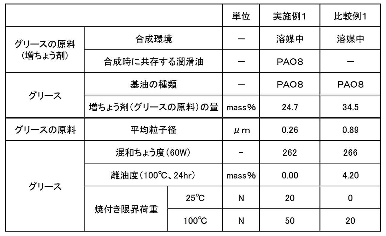
(1)トルエン100質量%に対して、1質量%のPAO8を合成時に共存する潤滑油として溶解した。更に、得られた溶液に所定量のオクチルアミンを混合し、混合液A3を得た。
(2)上記(1)の工程とは別に、トルエン100質量%に対して、所定量のMDIを混合し、混合液B3′を得た。
混合液A3の調製は、メカニカルスターラでトルエンを攪拌しながら、PAO8、オクチルアミンを添加することにより行った。
また、混合液B3′の調製は、メカニカルスターラでトルエンを攪拌しながら、MDIを添加することにより行った。
混合液A3の滴下が完了した後、0.5時間攪拌をつづけながら、室温下でオクチルアミンとMDIとを反応させ、ジウレア化合物を生成した。
このとき、グリースの原料の量は、基油とグリースの原料との合計量に対して、34.6質量%とした。
その後、ロールミルを用いた均質化処理を行い、グリースを完成した。
実施例2の(1)で、PAO8に代えてPAO6を合成時に共存する潤滑油として使用し、実施例2の(5)で投入するグリースの原料の量を、基油とグリースの原料との合計量に対して33.8質量%とした以外は、実施例2と同様にしてグリースを製造した。
基油としてのトリメリット酸エステルと、増ちょう剤としてのジウレアとを含有するグリースを下記の工程を経て調製した。
(2)基油、オクチルアミン、及び、4,4′-ジフェニルメタンジイソシアネート(MDI)を計量する。
(3)容器Aに、半量の基油(100℃)とMDIとを投入し、100℃で30分間撹拌する。
(4)容器Bに、残りの半量の基油(100℃)とオクチルアミンとを投入し、100℃で30分間撹拌する。
(6)容器B内のアミン溶液が、容器A内に全量投入されたことを確認した後、170℃まで昇温する。
(7)加熱しながら撹拌し、30分間、温度を170℃に保持する。
(8)加熱を止め、撹拌しながら自然放冷し、100℃まで冷却する。
(9)温度が100℃以下になったことを確認した後、撹拌を停止し、そのまま常温になるまで自然放冷する。
(10)ロールミルで均質化処理を実施する。
このような工程(1)~(10)を経て、グリースを完成した。
このグリースの増ちょう剤の量は、基油と増ちょう剤との合計量に対して、32.0質量である。
(1)実施例2の(1)~(4)と同様にして、グリースの原料を製造した。
(2)室温の基油としてのPAO6に、室温のグリースの原料を投入し、メカニカルスターラで攪拌しながら150℃まで加熱した。グリースの原料を混合した基油を150℃に維持しながら、1時間メカニカルスターラで攪拌し続けた。その後、メカニカルスターラで攪拌し続けながら、室温まで放冷し、攪拌を停止した。
このとき、グリースの原料の量は、基油とグリースの原料との合計量に対して、33.2質量%とした。
その後、ロールミルを用いた均質化処理を行い、グリースを完成した。
(1)実施例2の(1)において、1質量%のPAO8に代えて、1質量%のトリメリット酸エステルを合成時に共存する潤滑油として使用した以外は、実施例2の(1)~(4)と同様にして、グリースの原料を製造した。
(2)室温の基油としてのPAO8に、室温のグリースの原料を投入し、メカニカルスターラで攪拌しながら150℃まで加熱した。グリースの原料を混合した基油を150℃に維持しながら、1時間メカニカルスターラで攪拌し続けた。その後、メカニカルスターラで攪拌し続けながら、室温まで放冷し、攪拌を停止した。
このとき、グリースの原料の量は、基油とグリースの原料との合計量に対して、30.8質量%とした。
その後、ロールミルを用いた均質化処理を行い、グリースを完成した。
基油としてトリメリット酸エステルに代えて、PAO8を使用した以外は、比較例2と同様にして、グリースを製造した。
このグリースの増ちょう剤の量は、基油と増ちょう剤との合計量に対して、33.5質量とした。
1.平均粒子径の測定
実施例2~5で製造したグリースの原料について、増ちょう剤(ジウレア化合物)の平均粒子径を、上述した実施例1で採用した方法と同様の方法で測定した。結果を表4に示した。
実施例2~5で製造したグリース、及び、比較例2~3で製造したグリースについて、混和ちょう度(60W)をJIS K 2220:2013に準拠した方法で測定した。結果を表4に示した。
実施例2~5で製造したグリースについて、離油度をJIS K 2220:2013に準拠した方法で測定した。結果を表4に示した。
このとき、試験温度は100℃とし、24時間経過後の離油度を測定した。
実施例2~5で製造したグリース、及び、比較例2~3で製造したグリースについて、摩擦摩耗試験機(レスカ社製、フリクションプレーヤ FPR2100)を用いて、ボールオンディスク摩擦摩耗試験を行い、摩耗量(鋼球摩耗痕面積)を評価した。
ここでは、SUJ2製の軌道盤(軸軌道盤又はハウジング軌道盤)の側面上にグリースを塗布し、その上に接触面圧が2.4GPaになるように荷重を掛けてSUJ2製の鋼球を接触させた。
この状態で軌道盤を1800秒間回転させ、その後、鋼球の摩耗痕面積(mm2)を摩耗量として測定した。試験条件の詳細は表3に示した通りである。
結果は表4、及び図17、18に示した。図17には、トリメリット酸エステルを基油とするグリースの結果を示し、図18には、PAO(ポリ-α-オレフィン)を基油とするグリースの結果を示した。
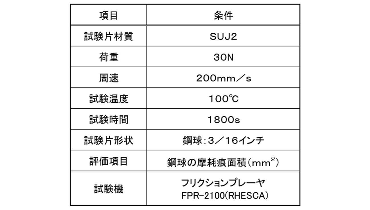

特に、トリメリット酸エステルを基油とし、PAOを合成時に共存する潤滑油とした場合は、耐摩耗性に優れることが明らかとなった。
31:ラック軸、310:第1のラック歯部、311:第1のラック歯、312:円筒面、313:円筒面、314:第2のラック歯部、315:第2のラック歯、
32:第1のピニオン軸、320:第1のピニオン歯部、321:第1のピニオン歯、392:第1のシート部材
54:第2のピニオン軸、540:第2のピニオン歯部、541:第2のピニオン歯、592:第2のシート部材
601:コラムタイプ電動パワーステアリング装置、602:ステアリングシャフト、603:ステアリングギヤ装置、633:ハウジング
631:ラック軸、710:ラック歯部、711:ラック歯、712:円筒面
632:ピニオン軸、720:ピニオン歯部、721:ピニオン歯、792:シート部材
801:玉軸受、802:内輪、803:外輪、804:玉、805:保持器、806:シール
G グリース
Claims (19)
- 増ちょう剤と、
潤滑油と、
前記潤滑油よりも沸点が低く、前記潤滑油を溶解するとともに前記増ちょう剤を溶解しない溶媒と、を含む、
グリースの原料。 - 第1の増ちょう剤原料と、
第2の増ちょう剤原料と、
第1の潤滑油と、
第2の潤滑油と、
前記第1の潤滑油及び前記第2の潤滑油よりも沸点が低く、前記第1の潤滑油を溶解するとともに、生成した増ちょう剤を溶解しない第1の溶媒と、
前記第1の潤滑油及び前記第2の潤滑油よりも沸点が低く、前記第2の潤滑油を溶解するとともに生成した増ちょう剤を溶解しない第2の溶媒と、を準備し、
前記第1の溶媒に、前記第1の潤滑油を溶解させるとともに、前記第1の増ちょう剤原料を溶解又は分散させて第1の混合液とし、
前記第2の溶媒に、前記第2の潤滑油を溶解させるとともに、前記第2の増ちょう剤原料を溶解又は分散させて第2の混合液とし、
前記第1の混合液と前記第2の混合液とを混合して、第1の増ちょう剤原料と第2の増ちょう剤原料とを反応させて増ちょう剤を生成する、
グリースの原料の製造方法。 - 前記増ちょう剤を生成した後、前記第1の溶媒と前記第2の溶媒とを除去する、請求項2に記載のグリースの原料の製造方法。
- 前記第1の潤滑油及び前記第2の潤滑油の少なくとも一方は、ポリ-α-オレフィンである請求項2又は3に記載のグリースの原料の製造方法。
- 第1の増ちょう剤原料と、
第2の増ちょう剤原料と、
第1の潤滑油と、
前記第1の潤滑油よりも沸点が低く、前記第1の潤滑油を溶解するとともに、生成した増ちょう剤を溶解しない第1の溶媒と、
前記第1の潤滑油よりも沸点が低く、生成した増ちょう剤を溶解しない第2の溶媒と、を準備し、
前記第1の溶媒に、前記第1の潤滑油を溶解させるとともに、前記第1の増ちょう剤原料を溶解又は分散させて第1の混合液とし、
前記第2の溶媒に、前記第2の増ちょう剤原料を溶解又は分散させて第2の混合液とし、
前記第1の混合液と前記第2の混合液とを混合して、前記第1の増ちょう剤原料と前記第2の増ちょう剤原料とを反応させて増ちょう剤を生成する、
グリースの原料の製造方法。 - 前記増ちょう剤を生成した後、前記第1の溶媒と前記第2の溶媒とを除去する、請求項5に記載のグリースの原料の製造方法。
- 前記第1の潤滑油は、ポリ-α-オレフィンである請求項5又は6に記載のグリースの原料の製造方法。
- 第1の増ちょう剤原料と、
第2の増ちょう剤原料と、
第1の潤滑油と、
前記第1の潤滑油よりも沸点が低く、生成した増ちょう剤を溶解しない第1の溶媒と、
前記第1の潤滑油よりも沸点が低く、生成した増ちょう剤を溶解しない第2の溶媒と、を準備し、
前記第1の溶媒に、前記第1の増ちょう剤原料を溶解又は分散させて第1の混合液とし、
前記第2の溶媒に、前記第2の増ちょう剤原料を溶解又は分散させて第2の混合液とし、
前記第1の混合液と前記第2の混合液と前記第1の潤滑油とを混合して、前記第1の増ちょう剤原料と前記第2の増ちょう剤原料とを反応させて増ちょう剤を生成する、
グリースの原料の製造方法。 - 前記増ちょう剤を生成した後、前記第1の溶媒と前記第2の溶媒とを除去する、請求項8に記載のグリースの原料の製造方法。
- 前記第1の潤滑油は、ポリ-α-オレフィンである請求項8又は9に記載のグリースの原料の製造方法。
- 増ちょう剤と、
第1の潤滑油と、
前記第1の潤滑油よりも沸点が低く、前記第1の潤滑油を溶解するとともに前記増ちょう剤を溶解しない第1の溶媒と、を準備し、
前記第1の潤滑油を前記第1の溶媒に溶解させて第1の溶液とし、得られた第1の溶液を前記増ちょう剤に含浸させる、
グリースの原料の製造方法。 - 前記第1の溶液を前記増ちょう剤に含浸させた後、前記第1の溶媒を除去する、請求項11に記載のグリースの原料の製造方法。
- 増ちょう剤と、
第1の潤滑油と、
前記第1の潤滑油よりも沸点が低く、前記第1の潤滑油を溶解するとともに前記増ちょう剤を溶解しない第1の溶媒と、を準備し、
前記第1の溶媒に、前記増ちょう剤を分散させて第1の混合液とし、得られた第1の混合液に前記第1の潤滑油を加える、
グリースの原料の製造方法。 - 前記第1の混合液に前記第1の潤滑油を加えた後、前記第1の溶媒を除去する、請求項13に記載のグリースの原料の製造方法。
- 請求項2、5又は8に記載の製造方法で製造されたグリースの原料に、第3の潤滑油を加え、
その後、前記第1の溶媒と前記第2の溶媒とを除去する、
グリースの製造方法。 - 請求項3、6、9、12又は14に記載の製造方法で製造されたグリースの原料に、第3の潤滑油を加える、
グリースの製造方法。 - 請求項11又は13に記載の製造方法で製造されたグリースの原料に、第3の潤滑油を加え、
その後、前記第1の溶媒を除去する、
グリースの製造方法。 - 前記第3の潤滑油は、エステル油、エーテル油、ポリ-α-オレフィン(PAO)、及び鉱油から選択される少なくとも1種である、請求項15~17のいずれか1項に記載のグリースの製造方法。
- 増ちょう剤と、基油と、添加剤とを含み、
前記増ちょうがジウレア化合物であり、
前記基油がポリ-α-オレフィン及びトリメリット酸エステルである、グリースであって、
前記増ちょう剤と前記基油との合計量に対して、
前記増ちょう剤の量が、20.0~40.0質量%、ポリ-α-オレフィンの量が、0.1~5.0質量%、トリメリット酸エステルの量が59.9~75質量%である、グリース。
Priority Applications (5)
| Application Number | Priority Date | Filing Date | Title |
|---|---|---|---|
| CN202180060725.8A CN116134117B (zh) | 2020-07-22 | 2021-07-14 | 润滑脂的原料、润滑脂的原料的制造方法、润滑脂的制造方法和润滑脂 |
| EP24215831.9A EP4491700B1 (en) | 2020-07-22 | 2021-07-14 | Method for producing grease |
| US18/013,485 US20230313066A1 (en) | 2020-07-22 | 2021-07-14 | Raw material of grease, method for producing raw material of grease, method for producing grease, and grease |
| JP2022537955A JP7552696B2 (ja) | 2020-07-22 | 2021-07-14 | グリースの原料、グリースの原料の製造方法、グリースの製造方法、および、グリース |
| EP21847065.6A EP4186965B1 (en) | 2020-07-22 | 2021-07-14 | Raw material of grease, method for producing raw material of grease, method for producing grease, and grease |
Applications Claiming Priority (2)
| Application Number | Priority Date | Filing Date | Title |
|---|---|---|---|
| JP2020-125473 | 2020-07-22 | ||
| JP2020125473 | 2020-07-22 |
Publications (1)
| Publication Number | Publication Date |
|---|---|
| WO2022019198A1 true WO2022019198A1 (ja) | 2022-01-27 |
Family
ID=79729486
Family Applications (1)
| Application Number | Title | Priority Date | Filing Date |
|---|---|---|---|
| PCT/JP2021/026499 Ceased WO2022019198A1 (ja) | 2020-07-22 | 2021-07-14 | グリースの原料、グリースの原料の製造方法、グリースの製造方法、および、グリース |
Country Status (5)
| Country | Link |
|---|---|
| US (1) | US20230313066A1 (ja) |
| EP (2) | EP4491700B1 (ja) |
| JP (1) | JP7552696B2 (ja) |
| CN (1) | CN116134117B (ja) |
| WO (1) | WO2022019198A1 (ja) |
Cited By (2)
| Publication number | Priority date | Publication date | Assignee | Title |
|---|---|---|---|---|
| WO2024053745A1 (ja) * | 2022-09-09 | 2024-03-14 | 天野エンザイム株式会社 | 加工植物性タンパク質含有組成物の製造方法 |
| WO2024150344A1 (ja) * | 2023-01-11 | 2024-07-18 | 株式会社ジェイテクト | マレイン酸系添加剤、グリース組成物および転がり軸受 |
Citations (14)
| Publication number | Priority date | Publication date | Assignee | Title |
|---|---|---|---|---|
| JPS54114506A (en) * | 1978-02-28 | 1979-09-06 | Nippon Koyu Kk | Lubricating grease composition |
| JPS5693799A (en) * | 1979-12-28 | 1981-07-29 | Mitsui Toatsu Chem Inc | Thickener composition |
| JPH05209183A (ja) * | 1991-09-24 | 1993-08-20 | Bayer Ag | ポリ尿素グリースの製造方法 |
| JPH06184577A (ja) * | 1992-12-21 | 1994-07-05 | Showa Shell Sekiyu Kk | ウレアグリースの製法 |
| JP2005105238A (ja) * | 2003-01-06 | 2005-04-21 | Nsk Ltd | 自動車電装補機用グリース組成物及び前記グリース組成物を封入した転がり軸受 |
| JP2006070263A (ja) | 2004-08-11 | 2006-03-16 | Rhein Chemie Rheinau Gmbh | 粉末(ポリ)尿素の調製方法 |
| JP2006070262A (ja) | 2004-08-11 | 2006-03-16 | Rhein Chemie Rheinau Gmbh | 噴霧乾燥による微紛(ポリ)尿素の調製方法 |
| WO2007026868A1 (ja) * | 2005-09-02 | 2007-03-08 | Ntn Corporation | 潤滑グリースおよび潤滑グリース封入転がり軸受 |
| JP2008163201A (ja) * | 2006-12-28 | 2008-07-17 | Kyodo Yushi Co Ltd | 等速ジョイント用グリース組成物及び等速ジョイント |
| JP2014214264A (ja) * | 2013-04-26 | 2014-11-17 | 出光興産株式会社 | グリースの製造方法およびグリース |
| JP2016506985A (ja) * | 2013-02-08 | 2016-03-07 | シエル・インターナシヨネイル・リサーチ・マーチヤツピイ・ベー・ウイShell Internationale Research Maatschappij Beslotenvennootshap | ウレアグリースの製造方法 |
| JP2016175962A (ja) * | 2015-03-18 | 2016-10-06 | Ntn株式会社 | グリース組成物 |
| JP2019081881A (ja) | 2017-10-31 | 2019-05-30 | 三洋化成工業株式会社 | 潤滑性向上剤 |
| JP2020125473A (ja) | 2019-02-01 | 2020-08-20 | コリア リサーチ インスティチュート オブ ケミカル テクノロジーKorea Research Institute Of Chemical Technology | ポリカーボネート−ナノセルロース複合素材およびその製造方法 |
Family Cites Families (8)
| Publication number | Priority date | Publication date | Assignee | Title |
|---|---|---|---|---|
| US3243372A (en) * | 1961-01-24 | 1966-03-29 | Chevron Res | Greases thickened with polyurea |
| JPS57108196A (en) * | 1980-12-17 | 1982-07-06 | Tokai Rika Co Ltd | Lubricating grease |
| DE3918107A1 (de) * | 1989-06-02 | 1990-12-06 | Klueber Lubrication | Schmierfettzusammensetzung |
| IT1263745B (it) * | 1992-01-22 | 1996-08-27 | Ntn Toyo Bearing Co Ltd | Cuscinetto a contatto di rotolamento chiuso a tenuta con grasso |
| DE102004044878A1 (de) * | 2004-09-14 | 2006-03-30 | Rhein Chemie Rheinau Gmbh | Verfahren zur Herstellung pulverförmiger Polyharnstoffe mittels Sprühtrocknung |
| DE102004039157A1 (de) * | 2004-08-11 | 2006-02-23 | Rhein Chemie Rheinau Gmbh | Verfahren zur Herstellung pulverförmiger Polyharnstoffe mittels Sprühtrocknung |
| US7923421B2 (en) * | 2006-01-24 | 2011-04-12 | Exxonmobil Research And Engineering Company | Process for preparing fine powder polyurea and greases therefrom |
| CN101440329B (zh) * | 2008-12-17 | 2012-02-08 | 山东红星化工有限公司 | 润滑脂用脲基稠化剂的生产方法 |
-
2021
- 2021-07-14 EP EP24215831.9A patent/EP4491700B1/en active Active
- 2021-07-14 WO PCT/JP2021/026499 patent/WO2022019198A1/ja not_active Ceased
- 2021-07-14 CN CN202180060725.8A patent/CN116134117B/zh active Active
- 2021-07-14 US US18/013,485 patent/US20230313066A1/en active Pending
- 2021-07-14 EP EP21847065.6A patent/EP4186965B1/en active Active
- 2021-07-14 JP JP2022537955A patent/JP7552696B2/ja active Active
Patent Citations (14)
| Publication number | Priority date | Publication date | Assignee | Title |
|---|---|---|---|---|
| JPS54114506A (en) * | 1978-02-28 | 1979-09-06 | Nippon Koyu Kk | Lubricating grease composition |
| JPS5693799A (en) * | 1979-12-28 | 1981-07-29 | Mitsui Toatsu Chem Inc | Thickener composition |
| JPH05209183A (ja) * | 1991-09-24 | 1993-08-20 | Bayer Ag | ポリ尿素グリースの製造方法 |
| JPH06184577A (ja) * | 1992-12-21 | 1994-07-05 | Showa Shell Sekiyu Kk | ウレアグリースの製法 |
| JP2005105238A (ja) * | 2003-01-06 | 2005-04-21 | Nsk Ltd | 自動車電装補機用グリース組成物及び前記グリース組成物を封入した転がり軸受 |
| JP2006070262A (ja) | 2004-08-11 | 2006-03-16 | Rhein Chemie Rheinau Gmbh | 噴霧乾燥による微紛(ポリ)尿素の調製方法 |
| JP2006070263A (ja) | 2004-08-11 | 2006-03-16 | Rhein Chemie Rheinau Gmbh | 粉末(ポリ)尿素の調製方法 |
| WO2007026868A1 (ja) * | 2005-09-02 | 2007-03-08 | Ntn Corporation | 潤滑グリースおよび潤滑グリース封入転がり軸受 |
| JP2008163201A (ja) * | 2006-12-28 | 2008-07-17 | Kyodo Yushi Co Ltd | 等速ジョイント用グリース組成物及び等速ジョイント |
| JP2016506985A (ja) * | 2013-02-08 | 2016-03-07 | シエル・インターナシヨネイル・リサーチ・マーチヤツピイ・ベー・ウイShell Internationale Research Maatschappij Beslotenvennootshap | ウレアグリースの製造方法 |
| JP2014214264A (ja) * | 2013-04-26 | 2014-11-17 | 出光興産株式会社 | グリースの製造方法およびグリース |
| JP2016175962A (ja) * | 2015-03-18 | 2016-10-06 | Ntn株式会社 | グリース組成物 |
| JP2019081881A (ja) | 2017-10-31 | 2019-05-30 | 三洋化成工業株式会社 | 潤滑性向上剤 |
| JP2020125473A (ja) | 2019-02-01 | 2020-08-20 | コリア リサーチ インスティチュート オブ ケミカル テクノロジーKorea Research Institute Of Chemical Technology | ポリカーボネート−ナノセルロース複合素材およびその製造方法 |
Non-Patent Citations (1)
| Title |
|---|
| See also references of EP4186965A4 |
Cited By (2)
| Publication number | Priority date | Publication date | Assignee | Title |
|---|---|---|---|---|
| WO2024053745A1 (ja) * | 2022-09-09 | 2024-03-14 | 天野エンザイム株式会社 | 加工植物性タンパク質含有組成物の製造方法 |
| WO2024150344A1 (ja) * | 2023-01-11 | 2024-07-18 | 株式会社ジェイテクト | マレイン酸系添加剤、グリース組成物および転がり軸受 |
Also Published As
| Publication number | Publication date |
|---|---|
| EP4491700A3 (en) | 2025-07-02 |
| EP4491700B1 (en) | 2026-01-14 |
| JPWO2022019198A1 (ja) | 2022-01-27 |
| US20230313066A1 (en) | 2023-10-05 |
| JP7552696B2 (ja) | 2024-09-18 |
| CN116134117B (zh) | 2025-08-01 |
| EP4491700A2 (en) | 2025-01-15 |
| EP4186965B1 (en) | 2025-11-19 |
| EP4186965A4 (en) | 2024-08-21 |
| CN116134117A (zh) | 2023-05-16 |
| EP4186965A1 (en) | 2023-05-31 |
Similar Documents
| Publication | Publication Date | Title |
|---|---|---|
| JP7042375B2 (ja) | ハブユニット | |
| JP5235278B2 (ja) | 潤滑剤組成物 | |
| WO2022019198A1 (ja) | グリースの原料、グリースの原料の製造方法、グリースの製造方法、および、グリース | |
| JP6736041B2 (ja) | グリース組成物および車両用転動装置 | |
| WO2005078053A1 (ja) | ステアリング用等速ジョイント用グリース組成物及びステアリング用等速ジョイント | |
| JP2019077765A (ja) | グリース組成物、転がり軸受、およびハブベアリング | |
| JP6960559B1 (ja) | ボールねじ装置、電動パワーステアリング装置およびボールねじ装置用潤滑剤 | |
| WO2006070893A1 (ja) | 伸縮軸 | |
| KR20160093041A (ko) | 그리스 조성물 | |
| JP7838580B2 (ja) | グリース組成物、及び、グリース組成物の製造方法 | |
| KR102097268B1 (ko) | 등속 조인트용 그리스 조성물 및 이를 봉입한 등속 조인트 | |
| JP2024070569A (ja) | グリース組成物、及びステアリングギヤ装置 | |
| JP2022024806A (ja) | グリース組成物および転がり軸受 | |
| CN100591938C (zh) | 伸缩轴 | |
| JP2025069644A (ja) | グリース組成物、及びステアリングギヤ装置 | |
| US12473510B2 (en) | Grease composition and steering gear device | |
| JP2021004335A (ja) | グリース組成物および転がり軸受 | |
| WO2024236658A1 (ja) | グリース組成物、及びステアリングギヤ装置 | |
| WO2025253518A1 (ja) | グリース組成物、及びステアリングギヤ装置 | |
| JP2026020673A (ja) | 歯車装置の製造方法、及び歯車装置 | |
| WO2024236661A1 (ja) | グリース組成物、及びステアリングギヤ装置 | |
| WO2017033954A1 (ja) | 車両用転動装置 | |
| WO2021246049A1 (ja) | グリース組成物および転がり軸受 |
Legal Events
| Date | Code | Title | Description |
|---|---|---|---|
| 121 | Ep: the epo has been informed by wipo that ep was designated in this application |
Ref document number: 21847065 Country of ref document: EP Kind code of ref document: A1 |
|
| DPE2 | Request for preliminary examination filed before expiration of 19th month from priority date (pct application filed from 20040101) | ||
| ENP | Entry into the national phase |
Ref document number: 2022537955 Country of ref document: JP Kind code of ref document: A |
|
| NENP | Non-entry into the national phase |
Ref country code: DE |
|
| ENP | Entry into the national phase |
Ref document number: 2021847065 Country of ref document: EP Effective date: 20230222 |
|
| WWG | Wipo information: grant in national office |
Ref document number: 202180060725.8 Country of ref document: CN |
|
| WWG | Wipo information: grant in national office |
Ref document number: 2021847065 Country of ref document: EP |