WO2022158014A1 - ハーネスブラケット及びヘルメット - Google Patents
ハーネスブラケット及びヘルメット Download PDFInfo
- Publication number
- WO2022158014A1 WO2022158014A1 PCT/JP2021/029778 JP2021029778W WO2022158014A1 WO 2022158014 A1 WO2022158014 A1 WO 2022158014A1 JP 2021029778 W JP2021029778 W JP 2021029778W WO 2022158014 A1 WO2022158014 A1 WO 2022158014A1
- Authority
- WO
- WIPO (PCT)
- Prior art keywords
- harness
- support
- liner
- cap body
- wiring
- Prior art date
- Legal status (The legal status is an assumption and is not a legal conclusion. Google has not performed a legal analysis and makes no representation as to the accuracy of the status listed.)
- Ceased
Links
Images



Classifications
-
- A—HUMAN NECESSITIES
- A42—HEADWEAR
- A42B—HATS; HEAD COVERINGS
- A42B3/00—Helmets; Helmet covers ; Other protective head coverings
- A42B3/04—Parts, details or accessories of helmets
- A42B3/10—Linings
- A42B3/12—Cushioning devices
- A42B3/125—Cushioning devices with a padded structure, e.g. foam
- A42B3/127—Cushioning devices with a padded structure, e.g. foam with removable or adjustable pads
-
- A—HUMAN NECESSITIES
- A42—HEADWEAR
- A42B—HATS; HEAD COVERINGS
- A42B3/00—Helmets; Helmet covers ; Other protective head coverings
- A42B3/04—Parts, details or accessories of helmets
-
- A—HUMAN NECESSITIES
- A42—HEADWEAR
- A42B—HATS; HEAD COVERINGS
- A42B3/00—Helmets; Helmet covers ; Other protective head coverings
- A42B3/04—Parts, details or accessories of helmets
- A42B3/08—Chin straps or similar retention devices
-
- F—MECHANICAL ENGINEERING; LIGHTING; HEATING; WEAPONS; BLASTING
- F41—WEAPONS
- F41H—ARMOUR; ARMOURED TURRETS; ARMOURED OR ARMED VEHICLES; MEANS OF ATTACK OR DEFENCE, e.g. CAMOUFLAGE, IN GENERAL
- F41H1/00—Personal protection gear
- F41H1/04—Protection helmets
Definitions
- the present disclosure relates to harness brackets and helmets.
- Patent Literature 1 describes a cheek pad that is an example of an interior pad.
- the interior parts attached to the cap body are attached to the inside of the cap body by the support parts welded to the cap body. Specifically, a tubular liner supporting portion welded to the cap body is fitted into a fitting hole provided in the liner, thereby positioning the liner to the cap body. The cheek pads are hooked on the pad supports welded to the hard hat, thereby positioning the cheek pads on the hard hat.
- the harness is fixed to a harness bracket as a harness supporting portion that is welded to the cap body, whereby the harness is positioned on the cap body.
- Each support part for supporting a plurality of interior parts is individually welded to the cap body.
- the protruding direction of each support portion and the welding position itself deviate from the desired (ideal) direction or position after welding.
- the relative positional deviation between the harness bracket and the liner support makes it easy to sandwich the harness between the liner and the harness bracket with a force greater than a predetermined load when attaching the liner.
- the relative positional deviation between the harness bracket and the pad support makes it easier to pinch the harness between the cheek pad and the harness bracket when attaching the cheek pad. As a result, when the liner or cheek pads are attached, the wiring portion of the harness may be pinched, causing disconnection of the harness.
- a harness bracket is a harness bracket that is attached to a cap body included in a helmet, and includes a base that is attached to the cap body, and the base is a first support that supports the harness.
- said first support configured to position said harness relative to said base; and a second support configured to support said liner, said support configured to position said liner relative to said base.
- a second support and a third support for supporting a cheek pad, the third support configured to position the cheek pad relative to the base.
- a helmet according to an aspect of the present disclosure is a helmet comprising a cap body and a harness bracket attached to the cap body, the harness bracket comprising a base attached to the cap body, the base comprising: A first support for supporting a harness, the first support configured to position the harness with respect to the base; and a second support for supporting a liner, the second support for supporting the liner. a second support configured to position relative to a base; and a third support configured to support a cheek pad, the third support configured to position the cheek pad relative to the base. and a support.
- FIG. 1 is a side view of a helmet according to one embodiment
- FIG. 2 is a front view of the helmet of FIG. 1
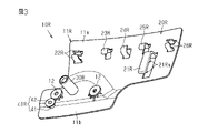
- FIG. 2 is a perspective view of a harness bracket of the helmet of FIG. 1
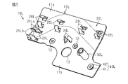
- FIG. 2 is a perspective view of a harness bracket of the helmet of FIG. 1
- FIG. 2 is a front view of a liner attached to the harness bracket of the helmet of FIG. 1
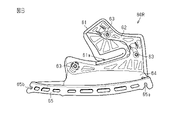
- FIG. 2 is a front view of the cheek pads of the helmet of FIG. 1
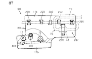
- FIG. FIG. 4 is a front view of a harness bracket showing a state in which a harness is attached to the harness bracket of FIG. 3;
- FIG. 1 to 7 front, rear, left, right, up, and down, which are directions viewed from the helmet wearer, are shown as front, back, left, right, up, and down with respect to the helmet.
- the helmet 1 is a full-face helmet.
- a helmet 1 includes a cap body 2 and harness brackets 10L and 10R.
- the cap body 2 constitutes the outer shell of the helmet.
- the cap body 2 is a resin member having a hemispherical shape.
- the material forming the cap 2 is selected from, for example, acrylonitrile-butadiene-styrene copolymer (ABS), polycarbonate (PC), and thermosetting resin impregnated with reinforcing fibers.
- the cap body 2 has an opening 2a that opens forward.
- the opening 2a secures the field of view of the wearer.
- a shield 3, which is a light-transmissive plate member, may be provided in the opening 2a. The shield 3 prevents foreign matter, rain, and wind flying from the front from entering the helmet 1, thereby improving the visibility of the wearer.
- the harness brackets 10L and 10R are parts for supporting harnesses connected to electronic equipment provided on the helmet 1.
- the harness brackets 10L and 10R are attached to left and right positions of the inner peripheral surface of the cap body 2 corresponding to the cheeks of the wearer.
- the harness bracket 10L is positioned on the left side as seen from the helmet 1 wearer.
- the harness bracket 10R is positioned on the right side as viewed from the wearer of the helmet 1. As shown in FIG.
- the cap body 2 accommodates a pair of left and right liners 50L and 50R, which are interior members for absorbing impact.
- a liner 50L is attached to the inner surface of the harness bracket 10L.
- Liner 50R is attached to the inner surface of harness bracket 10R.
- the liners 50L and 50R are made of foamed resin such as polystyrene foam.
- the liners 50L and 50R have a shape along the inner peripheral surface of the cap body 2 and have plane-symmetrical shapes.
- the helmet 1 may be provided with liners so as to cover the entire head such as the back of the head and the top of the head.
- the cap body 2 accommodates a pair of left and right cheek pads 60L and 60R, which are interior pads.
- the cheek pads 60L and 60R are brought into contact with the wearer's cheeks to enhance the adhesion between the helmet 1 and the wearer, thereby improving wearing comfort.
- the cheek pads 60L and 60R have plane-symmetrical shapes.
- the cheek pads 60L, 60R are provided inside the cap body 2 relative to the liners 50L, 50R.
- the cheek pads 60L are fixed to each of the cap body 2, the harness bracket 10L, and the liner 50L.
- the cheek pads 60R are fixed to each of the cap body 2, the harness bracket 10R, and the liner 50R.
- the helmet 1 includes, for example, a front pad that contacts the forehead, a rear pad that contacts the back of the head, side pads that contact the temporal region, a top pad that contacts the top of the head, and the like.
- Various interior pads may be provided. These interior pads have a repulsive force lower than that of the liners 50L and 50R on the inside of the cap body 2, and enhance the cushioning properties for the head.
- Helmet 1 may also include, for example, a chinstrap (not shown) for securing the wearer's chin to the helmet.
- the harness bracket 10R will be described below with reference to FIG. 3, the left direction in the figure is the front seen from the helmet 1 wearer, and the right direction in the figure is the rear seen from the helmet 1 wearer.
- the harness bracket 10R has a base 11R.
- the base 11 ⁇ /b>R has a plate shape that is three-dimensionally curved so as to follow the inner surface of the cap body 2 .
- the base 11R has an S shape when viewed from a viewpoint facing the inner surface of the base 11R.
- the base 11R is composed of a rectangular plate-shaped upper region 11a and a lower region 11b extending forward from the upper region 11a and extending forward from the upper region 11a.
- the vertical width of the upper region 11a is greater than the vertical width of the lower region 11b.
- the lower region 11b is integrated with the upper region 11a, and is arranged inside the upper region 11a in the horizontal direction of the cap body 2. As shown in FIG.
- the base 11R includes a plurality of fixing parts 12 having screw holes.
- the harness bracket 10R is fixed to the cap body 2 by screwing each fixing part 12 to the cap body 2 while the outer surface of the base 11R is in contact with the inner surface of the cap body 2 .
- the fixing means of the harness bracket 10R to the cap body 2 is not limited to screwing, and may be attached to the cap body 2 by any fixing means such as a fixing agent such as hot melt, double-sided tape, or the like.
- the upper region 11a of the harness bracket 10R includes a harness support portion 20R, which is an example of a first support portion.
- the harness support portion 20R includes a connection member support portion 21R and wiring support portions 22R to 26R.
- the connecting member supporting portion 21R and the wiring supporting portions 22R to 26R are provided on the inner surface of the upper region 11a.
- the connection member supporting portion 21R supports a connection member in a harness connected to electronic equipment provided on the helmet 1.
- the connection member in the harness is, for example, a relay connector that electrically connects wirings.
- the connecting member supporting portion 21R is located in the lower rear area in the upper area 11a.
- the lower region 11b is not positioned below the connection member support portion 21R, and the entire lower region 11b is positioned in front of the connection member support portion 21R in the front-rear direction.
- the connecting member supporting portion 21R has a hook shape that protrudes from the inner surface of the upper region 11a toward the inside of the cap body 2 and further extends downward.
- Two locking protrusions 21Ra are provided on the connection member support portion 21R.
- the connection member supporting portion 21R positions the connection member with respect to the base 11R by arranging the connection member between the two locking projections 21Ra and pressing the connection member toward the inner surface of the upper region 11a. .
- the wiring support portions 22R to 26R support wiring in harnesses connected to electronic devices provided on the helmet 1.
- the wiring support portions 22R to 26R are arranged at the same height in a region above the connection member support portion 21R in the upper region 11a.
- the wiring support portions 22R to 26R are arranged in a row in the order of the wiring support portions 22R, 23R, 24R, 25R and 26R from the front to the rear.
- the wiring support portion 22R is provided at the front end portion of the upper region 11a.
- the wiring support portions 22R are two vertically aligned support pieces that protrude from the upper region 11a toward the inside of the cap body 2 and curve toward each other.
- the wiring supporting portion 22R positions the wiring with respect to the base 11R by sandwiching the wiring.
- the wiring support portion 26R provided at the rear end portion of the upper region 11a has the same configuration as the wiring support portion 22R.
- the wiring support portions 23R to 25R are provided in the front-rear direction central portion of the upper region 11a.
- the wiring support portions 23R and 25R are support pieces that protrude from the upper region 11a toward the inside of the cap body 2 and curve downward.
- the wiring support portion 24R is a support piece that protrudes from the upper region 11a toward the inside of the cap body 2 and curves upward.
- the wiring supporting portions 23R to 25R position the wiring with respect to the base 11R by supporting the wiring from above with the wiring supporting portions 23R and 25R and supporting the wiring from below with the wiring supporting portion 24R.
- the lower region 11b of the harness bracket 10R includes a liner support portion 30R, which is an example of a second support portion, and a pad support portion 40R, which is an example of a third support portion.
- the liner support portion 30R has a cylindrical shape protruding toward the inside of the cap body 2 from the inner surface of the lower region 11b.
- the liner support portion 30R positions the liner 50R with respect to the base 11R by being inserted through the insertion hole 51 (see FIG. 5) provided in the liner 50R.
- the liner support portion 30R By positioning the liner support portion 30R below the harness support portion 20R, the liner 50R is attached at a position away from the wiring supported by the harness support portion 20R. Therefore, when attaching the liner 50R, it is possible to prevent the wiring from being caught.
- the pad support portion 40R is provided below and forward of the liner support portion 30R in the lower region 11b.
- the pad support portion 40 ⁇ /b>R includes an engaged portion 41 and an enlarged diameter portion 42 .
- the engaged portion 41 has a cylindrical shape protruding toward the inside of the cap body 2 from the inner surface of the lower region 11b.
- the enlarged diameter portion 42 is a flange portion having a larger diameter than the engaged portion 41 and is provided at the tip of the engaged portion 41 .
- the pad supporting portion 40R supports and positions the cheek pad 60R with respect to the base 11R by engaging the engaged portion 41 with the first engaging portion 65a (see FIG. 6) of the cheek pad 60R. .
- the cheek pad 60R is attached at a position away from the wiring supported by the harness support portion 20R. Therefore, it is possible to prevent the wiring from being pinched when attaching the cheek pad 60R.
- the harness support portion 20R, the liner support portion 30R, and the pad support portion 40R on the base 11R the positions of the harness, the liner 50R, and the cheek pads 60R are positioned relative to the harness bracket 10R, which is a resin molded product. Defined relatively. This prevents the wiring from being caught between the liner 50R and the base 11R and the wiring from being caught between the cheek pad 60R and the base 11R when the liner 50R and the cheek pad 60R are attached. That is, it is possible to suppress the pinching of the wiring in the harness.
- the liner 50R and the base 11R may be separated from each other due to displacement of the liner support portion 30R and displacement in the direction in which it extends. It is easy to get caught between If the wiring arranged above the pad supporting portion 40R sag even a little due to its own weight, it is likely to be caught between the cheek pad 60R and the base 11R due to the displacement of the pad supporting portion 40R.
- the harness support portion 20R, the liner support portion 30R, and the pad support portion 40R whose relative positions are defined with reference to the harness bracket 10R, which is a single resin molded product, there is no deviation in the supporting direction or relative position.
- the effect of suppressing the above-described pinching is further enhanced by the extent to which misalignment is less likely to occur.
- the liner supporting portion 30R and the pad supporting portion 40R are not positioned below the connection member where many wires gather, the connection can be performed without applying excessive tension to the wires gathered in the connection member to prevent them from hanging down. It is also possible to suppress the pinching of the wiring that gathers in the members.
- the connecting member supporting portion 21R, the liner supporting portion 30R, and the pad supporting portion 40R are arranged at different positions in the vertical direction and the front-rear direction, that is, in the circumferential direction of the cap body 2. This can improve the workability when attaching the liner 50R and the cheek pads 60R.
- the number of parts can be reduced compared to when the harness support portion 20R, the liner support portion 30R, and the pad support portion 40R are configured as separate parts.
- each part must be attached to the cap body 2.
- the harness bracket 10R is attached to the cap body 2 only. That is, the manufacturing process of the helmet 1 can be simplified.
- the harness bracket 10L will be described below with reference to FIG. 4, the right direction in the figure is the front seen from the helmet 1 wearer, and the left direction in the figure is the rear seen from the helmet 1 wearer.
- the harness bracket 10L has a base 11L.
- the base 11L has a shape substantially symmetrical with respect to the base 11R of the harness bracket 10R. That is, the base 11 ⁇ /b>L has a plate shape that is three-dimensionally curved so as to follow the inner surface of the cap body 2 .
- the base 11L has an inverted S shape when viewed from a viewpoint facing the inner surface of the base 11L.
- the base 11L is composed of an upper region 11a and a lower region 11b. Also in the harness bracket 10L, the lower region 11b is integrated with the upper region 11a, and is arranged inside the upper region 11a in the lateral direction of the cap body 2.
- the base 11L includes a plurality of fixing portions 12 having screw holes, and the harness bracket 10L is fixed to the cap body 2 by screwing the fixing portions 12 to the cap body 2 .
- the base 11L has a through-hole 13 arranged to straddle the upper region 11a and the lower region 11b.
- a harness of an electronic device attached to the outer surface of the cap body 2 is inserted through the through hole 13, and the harness is led out to the inside of the base 11L.
- the upper region 11a of the harness bracket 10L includes a harness support portion 20L, which is an example of a first support portion.
- the harness support portion 20L includes a connection member support portion 21L and wiring support portions 22L to 26L.
- the connecting member supporting portion 21L and the wiring supporting portions 22L to 26L are provided on the inner surface of the upper region 11a.
- connection member supporting portion 21L supports a connection member in a harness connected to electronic equipment provided in the helmet 1.
- the connection member support portion 21L is located in the lower rear region in the upper region 11a.
- the lower region 11b is not positioned below the connection member support portion 21L, and the entire lower region 11b is positioned in front of the connection member support portion 21L in the front-rear direction.
- the connecting member supporting portion 21L is two vertically aligned supporting walls erected toward the inside of the cap body 2 .
- a locking projection 21La is provided at the tip of the connecting member support portion 21L.
- the connecting member supporting portions 21L support and position the connecting member with respect to the base 11L by arranging and sandwiching the connecting member between the connecting member supporting portions 21L.
- connection member support portion 21L includes two auxiliary support walls 21Lb in the vicinity of the connection member support portion 21L.
- the two auxiliary support walls 21Lb support the connection member disposed between the connection member support portions 21L, thereby suppressing rattling of the connection member.
- the wiring support portions 22L to 26L support wiring in harnesses connected to electronic equipment provided in the helmet 1.
- the wiring support portion 22L is provided at the front end portion of the upper region 11a.
- the wiring support portion 23L is provided behind the wiring support portion 22L and at the same height as the wiring support portion 22L.
- Each of the wiring support portions 22L and 23L is two support pieces arranged in the vertical direction, protruding from the upper region 11a toward the inside of the cap body 2, and curved so as to approach each other.
- the wiring support portion 24L is provided above the through hole 13 and below the wiring support portions 22L and 23L.
- the wiring support portions 24L are two support pieces that incline upward and rearward, protrude from the upper region 11a toward the inside of the cap body 2, and curve so as to approach each other.
- the wiring support portion 24L supports, for example, the wiring led out to the inside of the base 11L through the through hole 13. As shown in FIG.
- Each of the wiring support portions 25L and 26L is two support pieces arranged with a larger gap in the vertical direction than the two support pieces forming each of the wiring support portions 22L and 23L.
- the wire support portion 25L is provided at a position rearward of the wire support portion 24L and forward of the wire support portion 26L. Further, the wiring support portion 26L is provided at the rear end portion of the upper region 11a.
- the two support pieces that constitute each of the wiring support portions 25L and 26L project from the upper region 11a toward the inside of the cap body 2 and have shapes that curve toward each other.
- the wiring support portions 25L and 26L collectively support, for example, the first wiring supported by the wiring support portions 22L and 23L and the second wiring supported by the wiring support portion 24L.
- a lower region 11b of the harness bracket 10L includes a liner support portion 30L, which is an example of a second support portion, and a pad support portion 40L, which is an example of a third support portion. Since the liner support portion 30L and the pad support portion 40L have the same configuration as the liner support portion 30R and the pad support portion 40R, description thereof will be omitted.
- the harness bracket 10R by providing the harness support portion 20L, the liner support portion 30L, and the pad support portion 40L on the base 11L, the mounting positions of the harness, the liner 50L, and the cheek pad 60L provided on the helmet 1 can be changed. is defined relatively. Thereby, when attaching the liner 50L and the cheek pad 60L, it is possible to suppress the pinching of the wiring in the harness.
- the liner 50R will be described below with reference to FIG. A description of the liner 50L, which has a plane-symmetrical shape with respect to the liner 50R, will be omitted. 5, the left direction in the figure is the front seen from the helmet 1 wearer, and the right direction in the figure is the rear seen from the helmet 1 wearer.
- the liner 50R is arranged inside the cap body 2 so as to cover the harness bracket 10R.
- the liner 50R has a curved shape that follows the inner surface of the cap body 2 .
- the liner 50R has an insertion hole 51 penetrating in the thickness direction of the liner 50R.
- the insertion hole 51 is provided at a position corresponding to the liner support portion 30R of the harness bracket 10R.
- the liner 50R is positioned with respect to the base 11R by inserting the liner support portion 30R into the insertion hole 51. As shown in FIG.
- the liner 50R includes a holder portion 52, wiring grooves 53, and three recesses 54 on the inner surface of the liner 50R, that is, the surface facing the cheek pad 60R.
- the holder portion 52 is, for example, a recess for holding an electronic device such as a speaker.
- the wiring groove 53 is a groove extending from the side edge of the liner 50R to the holder portion 52. As shown in FIG. Wiring in the harness is arranged in the wiring groove 53 .
- the recess 54 is provided with, for example, a male button (not shown) for attaching the cheek pad 60R.
- the cheek pad 60R will be described below with reference to FIG. A description of the cheek pad 60L, which has a plane-symmetrical shape with respect to the cheek pad 60R, will be omitted. 6, the right direction in the figure is the front seen from the helmet 1 wearer, and the left direction in the figure is the rear seen from the helmet 1 wearer.
- the cheek pad 60R has a body portion 61.
- the main body 61 is composed of a cushion such as urethane foam and a cover such as cloth that covers the cushion.
- the body portion 61 has a shape that follows the inner surface of the liner 50R. The body portion 61 abuts against the wearer's cheek, thereby increasing the adhesion between the helmet 1 and the wearer.
- the body portion 61 may have a slit 61a for inserting the chin strap.
- the cheek pad 60R includes a plate 62.
- the plate 62 is a plate made of flexible resin for holding the shape of the cushion forming the main body 61 .
- the plate body 62 is provided on the surface of the body portion 61 opposite to the surface that contacts the wearer's cheek.
- the plate 62 is a member facing the inner surface of the liner 50R in the cheek pad 60R.
- the female button 63 is attached to the surface of the main body 61 facing the liner 50R so as to protrude from a hole provided in the plate 62 .
- the body portion 61 of the cheek pad 60R is fixed inside the liner 50R by engaging the female button 63 with a male button provided on the liner 50R.
- the number of female buttons 63 and male buttons included in the liner 50R is not limited, and may be four or more or two or less.
- the cheek pad 60R has an extension 64.
- the extending portion 64 is a region from which the covering constituting the main body portion 61 extends under the surface of the main body portion 61 facing the liner 50R.
- a fixed piece 65 is provided at the tip of the extending portion 64 .
- the fixed piece 65 is composed of a flexible resin member.
- the fixed piece 65 has a first engaging portion 65 a located at the front end of the fixed piece 65 and a second engaging portion 65 b located at the rear end of the fixed piece 65 .
- the fixing piece 65 is inserted between the cap body 2 and the liner 50R, and the first engaging portion 65a is engaged with the engaged portion 41 to position the cheek pad 60R with respect to the harness bracket 10R. Further, the second engaging portion 65b is engaged with a boss-like engaging portion (not shown) provided on the cap body 2 .
- the fixing piece 65 By providing the fixing piece 65 at the tip of the extending portion 64 made of a covering such as cloth, the fixing piece 65 can be inserted between the cap body 2 and the liner 50R through the extending portion 64 .
- the fixing portion 12 provided in the harness bracket 10R is screwed to the cap body 2 .
- the harness bracket 10R is fixed to the cap body 2.
- the means for fixing the harness bracket 10R to the cap body 2 is not limited to screwing, and any fixing means may be used to attach the harness bracket 10R to the cap body 2 .
- a harness 70 connected to a plurality of electronic devices provided on the helmet 1 is attached to the harness bracket 10R.
- the harness 70 is composed of a wiring 71 connected to each of a plurality of electronic devices and a connection member 72 for relaying the wiring 71 .
- the connecting member 72 is, for example, a relay connector.
- the wiring 71 is positioned with respect to the base 11R by being supported by the wiring supporting portions 22R to 26R.
- the connection member 72 is positioned with respect to the base 11R by being supported by the connection member support portion 21R.
- the space above the liner support portion 30R and the pad support portion 40R can be used for routing the harness 70.
- the liner 50R is attached to the harness bracket 10R. Specifically, the liner support portion 30R is inserted through the insertion hole 51, and the liner 50R is fixed in a state of being positioned with respect to the base 11R. Then, the electronic device is arranged in the holder portion 52 and the wiring 71 is arranged in the wiring groove 53 .
- the cheek pads 60R are attached to the harness bracket 10R, the liner 50R, and the cap body 2. Specifically, first, the second engaging portion 65 b of the cheek pad 60 ⁇ /b>R is engaged with an engaging portion (not shown) provided on the cap body 2 .
- the fixing piece 65 of the cheek pad 60R is inserted between the cap body 2 and the liner 50R from below the cap body 2, and the first engaging portion 65a is engaged with the engaged portion 41.
- the pad support portion 40R is positioned below the harness support portion 20R and the liner support portion 30R, so that the first engaging portion 65a can easily engage the engaged portion 41. As shown in FIG. That is, it is possible to improve workability when attaching the cheek pads 60R.
- the body portion 61 of the cheek pad 60R is fixed to the inner surface of the liner 50R by engaging the female button 63 with the male button provided on the liner 50R.
- the harness bracket 10R, the liner 50R, and the cheek pads 60R are attached to the cap body 2 by the above procedure.
- the following effects can be obtained. (1) By providing the harness support portions 20L, 20R, the liner support portions 30L, 30R, and the pad support portions 40L, 40R on the bases 11L, 11R, the harness 70, the liners 50L, 50R, and the cheek pads 60L, 60R are relatively defined. This can prevent the wiring 71 of the harness 70 from being pinched when the liners 50L, 50R and the cheek pads 60L, 60R are attached. As a result, disconnection of the wiring 71 of the harness 70 can be prevented.
- the harness support portions 20L and 20R are positioned above the liner support portions 30L and 30R and the pad support portions 40L and 40R, thereby creating a space above the liner support portions 30L and 30R and the pad support portions 40L and 40R. can be used to route the harness 70.
- connection member support portions 21L, 21R, the liner support portions 30L, 30R, and the pad support portions 40L, 40R are arranged at different positions in the vertical direction and the circumferential direction of the cap body 2. Thereby, the workability of attaching the liners 50L, 50R and the cheek pads 60L, 60R can be improved.
- connection member support portions 21L, 21R, the liner support portions 30L, 30R, and the pad support portions 40L, 40R are arranged at different positions in the vertical direction and the circumferential direction of the cap body 2. ing.
- the arrangement of the connection member support portions 21L, 21R, the liner support portions 30L, 30R, and the pad support portions 40L, 40R is limited. not.
- the connection member support portions 21L, 21R and the pad support portions 40L, 40R may be provided at the same position in the circumferential direction of the cap body 2. In this case, by arranging the connecting member supporting portions 21L, 21R and the pad supporting portions 40L, 40R with a sufficient distance in the vertical direction, it is possible to improve workability when attaching the cheek pads 60L, 60R.
- the above embodiment illustrates a configuration in which the pad support portions 40L and 40R are positioned below the harness support portions 20L and 20R and the liner support portions 30L and 30R.
- the pad support portions 40L and 40R may be provided at the same height as the liner support portions 30L and 30R.
- the liner support portions 30L, 30R and the pad support portions 40L, 40R sufficiently apart in the circumferential direction of the cap body 2, it is possible to improve workability when attaching the cheek pads 60L, 60R.
- the above embodiment illustrates a configuration in which the harness support portions 20L and 20R are positioned above the liner support portions 30L and 30R and the pad support portions 40L and 40R.
- the harness support portions 20L and 20R may be provided at the same height as the liner support portions 30L and 30R, for example.
- the harness support portions 20L and 20R may be provided at the same height as the pad support portions 40L and 40R. Even in these cases, the harness support portions 20L and 20R are sufficiently spaced apart from the liner support portions 30L and 30R and the pad support portions 40L and 40R in the circumferential direction of the cap body 2.
- the shape of the liners 50L, 50R is not limited as long as they are configured to be attachable to the liner support portions 30L, 30R.
- the liners 50L and 50R do not have to be symmetrical with each other.
- the shape of the cheek pads 60L, 60R is not limited as long as it can be attached to the pad support portions 40L, 40R.
- the cheek pads 60L and 60R do not have to be symmetrical to each other.
- each part constituting the harness support parts 20L and 20R may be appropriately determined according to the shape of the wiring 71 and the connection member 72 constituting the harness 70 and the routing of the harness 70 .
- the connecting member supporting portion 21L and the connecting member supporting portion 21R have different shapes. There may be.
- the harness support portions 20L and 20R may be configured to be plane-symmetrical to each other.
- the arrangement of the harness support portions 20L, 20R, the liner support portions 30L, 30R, and the pad support portions 40L, 40R in the harness brackets 10L, 10R is not limited to the configuration of the present embodiment. That is, any configuration that can suppress the pinching of the wiring 71 when attaching the liners 50L, 50R and the cheek pads 60L, 60R may be employed.
- the harness brackets 10L and 10R may be plane-symmetrical to each other.
- the helmet 1 is a full-face helmet, but is not limited to this. It may be a helmet with a chin, or a convertible helmet that can be fixed to the back of the head by rotating the chin.
Landscapes
- Helmets And Other Head Coverings (AREA)
Abstract
Description
図1に示すように、ヘルメット1は、フルフェイス型のヘルメットである。ヘルメット1は、帽体2と、ハーネスブラケット10L,10Rとを備える。
以下、図3を参照して、ハーネスブラケット10Rについて説明する。なお、図3では、図中左方向がヘルメット1の装着者から見た前方であり、図中右方向がヘルメット1の装着者から見た後方である。
以下では、図5を参照してライナー50Rについて説明する。なお、ライナー50Rと互いに面対称の形状を有するライナー50Lについての説明は省略する。また、図5では、図中左方向がヘルメット1の装着者から見た前方であり、図中右方向がヘルメット1の装着者から見た後方である。
以下では、図6を参照してチークパッド60Rについて説明する。なお、チークパッド60Rと互いに面対称の形状であるチークパッド60Lについての説明は省略する。また、図6では、図中右方向がヘルメット1の装着者から見た前方であり、図中左方向がヘルメット1の装着者から見た後方である。
以下、図7を参照してヘルメット1の作用について説明する。具体的に、以下では、帽体2に対して、ハーネスブラケット10R、ライナー50R、及び、チークパッド60Rを取り付ける手順を説明する。なお、ハーネスブラケット10L、ライナー50L、及び、チークパッド60Lは、同様の手順で帽体2に取り付けられる。また、図7では、図中左方向がヘルメット1の装着者から見た前方であり、図中右方向がヘルメット1の装着者から見た後方である。
上記実施形態によれば、以下に列挙する効果を得ることができる。
(1)ベース11L,11Rにハーネス支持部20L,20R、ライナー支持部30L,30R、及び、パッド支持部40L,40Rを設けることで、ハーネス70、ライナー50L,50R、及び、チークパッド60L,60Rの取り付け位置が相対的に規定される。これにより、ライナー50L,50R及びチークパッド60L,60Rを取り付ける際に、ハーネス70の配線71が挟み込まれることを抑制できる。結果として、ハーネス70の配線71が断線することを防止できる。
・上記実施形態は、接続部材支持部21L,21R、ライナー支持部30L,30R、及び、パッド支持部40L,40Rが上下方向及び帽体2の周方向において異なる位置に配置される構成を例示している。しかし、ライナー50L,50R及びチークパッド60L,60Rの取り付け作業を好適に行えるのであれば、接続部材支持部21L,21R、ライナー支持部30L,30R、及び、パッド支持部40L,40Rの配置は限定されない。例えば、接続部材支持部21L,21Rとパッド支持部40L,40Rとを、帽体2の周方向において同じ位置に設けてもよい。この場合、接続部材支持部21L,21Rとパッド支持部40L,40Rとを上下方向において十分に離間して配置することで、チークパッド60L,60Rを取り付ける際の作業性を向上できる。
Claims (6)
- ヘルメットが備える帽体に取り付けられるように構成されたハーネスブラケットであって、
前記帽体に取り付けられるベースを備え、
前記ベースは、
ハーネスを支持する第1支持部であって、前記ハーネスを前記ベースに対して位置決めするように構成された前記第1支持部と、
ライナーを支持する第2支持部であって、前記ライナーを前記ベースに対して位置決めするように構成された前記第2支持部と、
チークパッドを支持する第3支持部であって、前記チークパッドを前記ベースに対して位置決めするように構成された前記第3支持部と、を備える
ハーネスブラケット。 - 前記第1支持部は、前記第2支持部よりも上方に位置する
請求項1に記載のハーネスブラケット。 - 前記第1支持部は、前記第3支持部よりも上方に位置する
請求項1または2に記載のハーネスブラケット。 - 前記第3支持部は、前記第1支持部及び前記第2支持部よりも下方に位置する
請求項1ないし3のうち何れか一項に記載のハーネスブラケット。 - 前記第1支持部は、前記ハーネスにおける接続部材を支持する接続部材支持部と、前記ハーネスにおける配線を支持する配線支持部と、を備え、
前記接続部材支持部、前記第2支持部、及び、前記第3支持部は、上下方向及び前記帽体の周方向において異なる位置に配置される
請求項1ないし4のうち何れか一項に記載のハーネスブラケット。 - 帽体と、前記帽体に取り付けられるハーネスブラケットと、を備えるヘルメットであって、
前記ハーネスブラケットは、前記帽体に取り付けられるベースを備え、
前記ベースは、
ハーネスを支持する第1支持部であって、前記ハーネスを前記ベースに対して位置決めするように構成された前記第1支持部と、
ライナーを支持する第2支持部であって、前記ライナーを前記ベースに対して位置決めするように構成された前記第2支持部と、
チークパッドを支持する第3支持部であって、前記チークパッドを前記ベースに対して位置決めするように構成された前記第3支持部と、を備える
ヘルメット。
Priority Applications (3)
| Application Number | Priority Date | Filing Date | Title |
|---|---|---|---|
| CN202180068645.7A CN116322413B (zh) | 2021-01-19 | 2021-08-12 | 线束支架及头盔 |
| EP21921119.0A EP4282297B1 (en) | 2021-01-19 | 2021-08-12 | Harness bracket and helmet |
| US18/253,259 US12262773B2 (en) | 2021-01-19 | 2021-08-12 | Harness bracket and helmet |
Applications Claiming Priority (2)
| Application Number | Priority Date | Filing Date | Title |
|---|---|---|---|
| JP2021006413A JP7333352B2 (ja) | 2021-01-19 | 2021-01-19 | ハーネスブラケット及びヘルメット |
| JP2021-006413 | 2021-01-19 |
Publications (1)
| Publication Number | Publication Date |
|---|---|
| WO2022158014A1 true WO2022158014A1 (ja) | 2022-07-28 |
Family
ID=82549652
Family Applications (1)
| Application Number | Title | Priority Date | Filing Date |
|---|---|---|---|
| PCT/JP2021/029778 Ceased WO2022158014A1 (ja) | 2021-01-19 | 2021-08-12 | ハーネスブラケット及びヘルメット |
Country Status (5)
| Country | Link |
|---|---|
| US (1) | US12262773B2 (ja) |
| EP (1) | EP4282297B1 (ja) |
| JP (1) | JP7333352B2 (ja) |
| CN (1) | CN116322413B (ja) |
| WO (1) | WO2022158014A1 (ja) |
Citations (9)
| Publication number | Priority date | Publication date | Assignee | Title |
|---|---|---|---|---|
| US4023209A (en) * | 1975-12-17 | 1977-05-17 | Gentex Corporation | Protective helmet assembly with segmental outer shell |
| JPS58169505A (ja) * | 1982-03-08 | 1983-10-06 | リノ・フアンテイン | クラツシユヘルメツトのバイザ開閉装置 |
| JPH01177233U (ja) * | 1988-05-31 | 1989-12-18 | ||
| EP0980174A2 (en) * | 1998-05-19 | 2000-02-16 | Blu s.r.l. | Integrated protective helmet for handsfree use of a mobile telephone in a car |
| US20090126059A1 (en) * | 2007-11-20 | 2009-05-21 | Tack David W | Head protection system |
| JP2014009428A (ja) * | 2012-07-02 | 2014-01-20 | Arai Helmet Ltd | マイクロフォンの保持装置及びオープンフェースヘルメット |
| US9631899B2 (en) * | 2011-03-14 | 2017-04-25 | Revision Military S.A.R.L. | Ballistic and impact protective military helmet assembly |
| JP2018115410A (ja) | 2017-01-20 | 2018-07-26 | 株式会社Shoei | ネックカバー及びヘルメット |
| WO2020130029A1 (ja) * | 2018-12-20 | 2020-06-25 | Nsウエスト株式会社 | ヘルメット及び充電システム |
Family Cites Families (19)
| Publication number | Priority date | Publication date | Assignee | Title |
|---|---|---|---|---|
| JPH01221504A (ja) * | 1988-02-28 | 1989-09-05 | Honda Motor Co Ltd | ヘルメットの音響装置 |
| JPH0650499Y2 (ja) * | 1989-01-18 | 1994-12-21 | 本田技研工業株式会社 | 電装品付ヘルメット |
| JPH0639721B2 (ja) * | 1990-08-15 | 1994-05-25 | 昭栄化工株式会社 | ヘルメット |
| JP3955127B2 (ja) * | 1997-05-19 | 2007-08-08 | 学 根本 | ヘルメット |
| JP4592870B2 (ja) * | 2000-05-01 | 2010-12-08 | 株式会社Shoei | ヘルメット |
| US7207071B2 (en) * | 2004-06-18 | 2007-04-24 | Fox Racing, Inc. | Ventilated helmet system |
| JP4948893B2 (ja) * | 2006-05-09 | 2012-06-06 | 株式会社Shoei | ヘルメットおよびその脱着方法 |
| JP5041906B2 (ja) * | 2007-08-07 | 2012-10-03 | 株式会社Shoei | ヘルメット |
| JP5145873B2 (ja) * | 2007-11-05 | 2013-02-20 | Dicプラスチック株式会社 | ヘルメット |
| JP5159556B2 (ja) * | 2008-10-22 | 2013-03-06 | 株式会社Shoei | ヘルメットおよびその脱着方法 |
| KR100993836B1 (ko) * | 2010-03-19 | 2010-11-12 | 주식회사 산청 | 보호용 헬멧 |
| US8549671B2 (en) * | 2011-01-06 | 2013-10-08 | Bell Sports, Inc. | Helmet having magnetically coupled cheek pads |
| JP6296611B2 (ja) * | 2014-08-05 | 2018-03-20 | 株式会社Shoei | ヘルメット |
| KR101772124B1 (ko) * | 2015-11-30 | 2017-09-12 | 주식회사 기도스포츠 | 헬멧의 탈착식 패드 체결 구조 및 이를 포함하는 헬멧 |
| CN106072960B (zh) * | 2016-07-13 | 2023-03-14 | 杭州克霾环保科技有限公司 | 一种防雾霾帽 |
| IT201600083163A1 (it) * | 2016-08-05 | 2018-02-05 | Nolangroup Spa | Casco con elemento di imbottitura rimovibile |
| KR101995947B1 (ko) * | 2017-07-17 | 2019-07-03 | 주식회사 홍진에이치제이씨 | 비상시 패드 제거가 가능한 헬멧 |
| EP3479714B1 (en) * | 2017-11-07 | 2020-06-03 | Locatelli S.p.A. | Protective helmet |
| ES3061988T3 (en) * | 2019-12-16 | 2026-04-08 | Ogk Kabuto Co Ltd | Helmet |
-
2021
- 2021-01-19 JP JP2021006413A patent/JP7333352B2/ja active Active
- 2021-08-12 WO PCT/JP2021/029778 patent/WO2022158014A1/ja not_active Ceased
- 2021-08-12 EP EP21921119.0A patent/EP4282297B1/en active Active
- 2021-08-12 CN CN202180068645.7A patent/CN116322413B/zh active Active
- 2021-08-12 US US18/253,259 patent/US12262773B2/en active Active
Patent Citations (9)
| Publication number | Priority date | Publication date | Assignee | Title |
|---|---|---|---|---|
| US4023209A (en) * | 1975-12-17 | 1977-05-17 | Gentex Corporation | Protective helmet assembly with segmental outer shell |
| JPS58169505A (ja) * | 1982-03-08 | 1983-10-06 | リノ・フアンテイン | クラツシユヘルメツトのバイザ開閉装置 |
| JPH01177233U (ja) * | 1988-05-31 | 1989-12-18 | ||
| EP0980174A2 (en) * | 1998-05-19 | 2000-02-16 | Blu s.r.l. | Integrated protective helmet for handsfree use of a mobile telephone in a car |
| US20090126059A1 (en) * | 2007-11-20 | 2009-05-21 | Tack David W | Head protection system |
| US9631899B2 (en) * | 2011-03-14 | 2017-04-25 | Revision Military S.A.R.L. | Ballistic and impact protective military helmet assembly |
| JP2014009428A (ja) * | 2012-07-02 | 2014-01-20 | Arai Helmet Ltd | マイクロフォンの保持装置及びオープンフェースヘルメット |
| JP2018115410A (ja) | 2017-01-20 | 2018-07-26 | 株式会社Shoei | ネックカバー及びヘルメット |
| WO2020130029A1 (ja) * | 2018-12-20 | 2020-06-25 | Nsウエスト株式会社 | ヘルメット及び充電システム |
Non-Patent Citations (1)
| Title |
|---|
| See also references of EP4282297A4 |
Also Published As
| Publication number | Publication date |
|---|---|
| EP4282297A1 (en) | 2023-11-29 |
| CN116322413A (zh) | 2023-06-23 |
| JP2022110789A (ja) | 2022-07-29 |
| EP4282297B1 (en) | 2026-05-13 |
| JP7333352B2 (ja) | 2023-08-24 |
| US20240016251A1 (en) | 2024-01-18 |
| US12262773B2 (en) | 2025-04-01 |
| CN116322413B (zh) | 2025-09-19 |
| EP4282297A4 (en) | 2024-11-20 |
Similar Documents
| Publication | Publication Date | Title |
|---|---|---|
| ES2372225T3 (es) | Sistema de comunicaciones en el relleno acolchado cervical de un casco. | |
| EP1714569B1 (en) | Bicycle helmet | |
| EP3094517B1 (en) | Vehicle headrest | |
| US9327628B2 (en) | Automobile headrest | |
| JP5463399B2 (ja) | チャイルドシート用監視及び/又は娯楽システム | |
| EP2536304B1 (en) | Protective helmet | |
| US20180249779A1 (en) | Helmet Systems And Method For Operating The Same | |
| CN105711530B (zh) | 车载设备的设置结构 | |
| US9656579B2 (en) | Headrest and vehicle seat | |
| JP7333352B2 (ja) | ハーネスブラケット及びヘルメット | |
| JP2012072540A (ja) | 保護ヘルメット | |
| WO1990014778A1 (en) | Improvements in or relating to safety helmets | |
| CN217532690U (zh) | 一种前保险杠与前照灯的连接结构、前围总成及汽车 | |
| JP2010062732A (ja) | ヘッドホン | |
| JP2015073204A (ja) | イヤーフック | |
| CN221851850U (zh) | 转向护罩总成和具有其的车辆 | |
| CN215420703U (zh) | 一种头带及头戴耳机 | |
| JP7103652B2 (ja) | 自転車用ヘルメットに好適なサイズ調整機能を備えたヘッドレスト | |
| JP7104329B2 (ja) | シートへのセンサーの配置構造及び乗物用シート | |
| JP2026070587A (ja) | 頭部保護具用内装材及び折畳み式ずきん | |
| KR20220084542A (ko) | 트랙터의 보호구조물(rops)용 유닛 어셈블리 | |
| KR200164011Y1 (ko) | 헬멧 | |
| JP2018047899A5 (ja) | エアバッグモジュール装備シート | |
| JP2016113129A (ja) | 車載機器の配設構造 | |
| ITMI20090744A1 (it) | Casco di protezione, particolarmente per uso motociclistico e/o automobilistico, con dispositivo di ancoraggio del sistema di comunicazione perfezionato. |
Legal Events
| Date | Code | Title | Description |
|---|---|---|---|
| 121 | Ep: the epo has been informed by wipo that ep was designated in this application |
Ref document number: 21921119 Country of ref document: EP Kind code of ref document: A1 |
|
| WWE | Wipo information: entry into national phase |
Ref document number: 18253259 Country of ref document: US |
|
| NENP | Non-entry into the national phase |
Ref country code: DE |
|
| ENP | Entry into the national phase |
Ref document number: 2021921119 Country of ref document: EP Effective date: 20230821 |
|
| WWG | Wipo information: grant in national office |
Ref document number: 18253259 Country of ref document: US |
|
| WWG | Wipo information: grant in national office |
Ref document number: 202180068645.7 Country of ref document: CN |
|
| WWG | Wipo information: grant in national office |
Ref document number: 2021921119 Country of ref document: EP |