WO2023021772A1 - Dispositif de mesure de température - Google Patents
Dispositif de mesure de température Download PDFInfo
- Publication number
- WO2023021772A1 WO2023021772A1 PCT/JP2022/013087 JP2022013087W WO2023021772A1 WO 2023021772 A1 WO2023021772 A1 WO 2023021772A1 JP 2022013087 W JP2022013087 W JP 2022013087W WO 2023021772 A1 WO2023021772 A1 WO 2023021772A1
- Authority
- WO
- WIPO (PCT)
- Prior art keywords
- heat
- heat pipe
- temperature
- measuring device
- temperature sensor
- Prior art date
- Legal status (The legal status is an assumption and is not a legal conclusion. Google has not performed a legal analysis and makes no representation as to the accuracy of the status listed.)
- Ceased
Links
Images



Classifications
-
- G—PHYSICS
- G01—MEASURING; TESTING
- G01K—MEASURING TEMPERATURE; MEASURING QUANTITY OF HEAT; THERMALLY-SENSITIVE ELEMENTS NOT OTHERWISE PROVIDED FOR
- G01K1/00—Details of thermometers not specially adapted for particular types of thermometer
- G01K1/16—Special arrangements for conducting heat from the object to the sensitive element
-
- G—PHYSICS
- G01—MEASURING; TESTING
- G01K—MEASURING TEMPERATURE; MEASURING QUANTITY OF HEAT; THERMALLY-SENSITIVE ELEMENTS NOT OTHERWISE PROVIDED FOR
- G01K13/00—Thermometers specially adapted for specific purposes
- G01K13/02—Thermometers specially adapted for specific purposes for measuring temperature of moving fluids or granular materials capable of flow
- G01K13/026—Thermometers specially adapted for specific purposes for measuring temperature of moving fluids or granular materials capable of flow of moving liquids
-
- F—MECHANICAL ENGINEERING; LIGHTING; HEATING; WEAPONS; BLASTING
- F28—HEAT EXCHANGE IN GENERAL
- F28D—HEAT-EXCHANGE APPARATUS, NOT PROVIDED FOR IN ANOTHER SUBCLASS, IN WHICH THE HEAT-EXCHANGE MEDIA DO NOT COME INTO DIRECT CONTACT
- F28D15/00—Heat-exchange apparatus with the intermediate heat-transfer medium in closed tubes passing into or through the conduit walls ; Heat-exchange apparatus employing intermediate heat-transfer medium or bodies
- F28D15/02—Heat-exchange apparatus with the intermediate heat-transfer medium in closed tubes passing into or through the conduit walls ; Heat-exchange apparatus employing intermediate heat-transfer medium or bodies in which the medium condenses and evaporates, e.g. heat pipes
-
- G—PHYSICS
- G01—MEASURING; TESTING
- G01K—MEASURING TEMPERATURE; MEASURING QUANTITY OF HEAT; THERMALLY-SENSITIVE ELEMENTS NOT OTHERWISE PROVIDED FOR
- G01K1/00—Details of thermometers not specially adapted for particular types of thermometer
- G01K1/14—Supports; Fastening devices; Arrangements for mounting thermometers in particular locations
-
- H—ELECTRICITY
- H05—ELECTRIC TECHNIQUES NOT OTHERWISE PROVIDED FOR
- H05K—PRINTED CIRCUITS; CASINGS OR CONSTRUCTIONAL DETAILS OF ELECTRIC APPARATUS; MANUFACTURE OF ASSEMBLAGES OF ELECTRICAL COMPONENTS
- H05K7/00—Constructional details common to different types of electric apparatus
- H05K7/20—Modifications to facilitate cooling, ventilating, or heating
-
- H—ELECTRICITY
- H01—ELECTRIC ELEMENTS
- H01M—PROCESSES OR MEANS, e.g. BATTERIES, FOR THE DIRECT CONVERSION OF CHEMICAL ENERGY INTO ELECTRICAL ENERGY
- H01M10/00—Secondary cells; Manufacture thereof
- H01M10/60—Heating or cooling; Temperature control
- H01M10/61—Types of temperature control
- H01M10/613—Cooling or keeping cold
-
- H—ELECTRICITY
- H01—ELECTRIC ELEMENTS
- H01M—PROCESSES OR MEANS, e.g. BATTERIES, FOR THE DIRECT CONVERSION OF CHEMICAL ENERGY INTO ELECTRICAL ENERGY
- H01M10/00—Secondary cells; Manufacture thereof
- H01M10/60—Heating or cooling; Temperature control
- H01M10/65—Means for temperature control structurally associated with the cells
- H01M10/656—Means for temperature control structurally associated with the cells characterised by the type of heat-exchange fluid
- H01M10/6569—Fluids undergoing a liquid-gas phase change or transition, e.g. evaporation or condensation
-
- Y—GENERAL TAGGING OF NEW TECHNOLOGICAL DEVELOPMENTS; GENERAL TAGGING OF CROSS-SECTIONAL TECHNOLOGIES SPANNING OVER SEVERAL SECTIONS OF THE IPC; TECHNICAL SUBJECTS COVERED BY FORMER USPC CROSS-REFERENCE ART COLLECTIONS [XRACs] AND DIGESTS
- Y02—TECHNOLOGIES OR APPLICATIONS FOR MITIGATION OR ADAPTATION AGAINST CLIMATE CHANGE
- Y02E—REDUCTION OF GREENHOUSE GAS [GHG] EMISSIONS, RELATED TO ENERGY GENERATION, TRANSMISSION OR DISTRIBUTION
- Y02E60/00—Enabling technologies; Technologies with a potential or indirect contribution to GHG emissions mitigation
- Y02E60/10—Energy storage using batteries
Definitions
- the present invention relates to a temperature measuring device.
- This application claims priority based on Japanese Patent Application No. 2021-133131 filed in Japan on August 18, 2021, the content of which is incorporated herein.
- Patent Document 1 a temperature measuring device as shown in Patent Document 1 has been known.
- This temperature measuring device has a plurality of temperature sensors to measure the temperature of a plurality of arranged heat sources (battery cells). By measuring the temperature of multiple battery cells, abnormalities are detected based on temperature changes in the battery.
- Patent Document 1 a plurality of temperature sensors are arranged according to the number of heat sources. In addition, since a circuit for outputting measurement data is connected to each of the plurality of temperature sensors, the size of the temperature measurement device may increase.
- the present invention has been made in consideration of such circumstances, and an object of the present invention is to provide a temperature measuring device capable of measuring temperature changes of a plurality of heat sources with a single temperature sensor.
- a temperature measuring device includes a heat pipe having a container in which a working fluid is sealed, a temperature sensor for detecting the temperature of the heat pipe, and a temperature sensor connected to the temperature sensor. and a wired wire portion, the heat pipe receiving heat from a plurality of heat sources.
- the temperature measuring device of the above aspect it is possible to quickly detect an abnormality in a plurality of heat sources with a simple configuration.
- the temperature measuring device further includes a contact surface expansion plate positioned between the plurality of heat sources and the heat pipe, the heat pipe has a flat shape, and the contact surface expansion plate has a thickness of the heat pipe. It may be in the form of a plate extending perpendicularly to the longitudinal direction.
- the temperature measuring device further includes an insulating layer positioned between the plurality of heat sources and the heat pipe, the heat pipe having a flat shape, and the insulating layer extending perpendicularly to the thickness direction of the heat pipe. It may be in the form of a plate that extends in such a way as to
- the temperature measuring device further includes a height adjustment layer positioned between the plurality of heat sources and the heat pipe, the heat pipe has a flat shape, and the height adjustment layer has a thickness of the heat pipe. It may be in the form of a plate extending perpendicularly to the longitudinal direction.
- the wire portion may be an FPC.
- the temperature sensor may be arranged at a first end in the longitudinal direction of the heat pipe, and the first end of the heat pipe may serve as a condensing portion where vapor of the working fluid is condensed.
- the temperature measurement device may further include a heat sink arranged at the second end in the longitudinal direction of the heat pipe.
- the temperature measuring device may further include a cold plate having an inlet and an outlet for cooling liquid, and the plurality of heat sources may be arranged between the cold plate and the heat pipe.
- thermoelectric measuring device capable of measuring temperature changes of a plurality of heat sources with one temperature sensor.
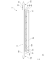
- FIG. 1 is a top view of a temperature measuring device according to a first embodiment;
- FIG. 1 is a side view of a temperature measuring device according to a first embodiment;
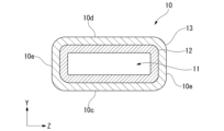
- FIG. It is a cross-sectional view of a heat pipe.
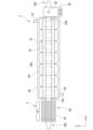
- It is a top view of a temperature measuring device according to a second embodiment.
- It is a side view of a temperature measuring device according to a second embodiment.
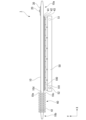
- It is a top view of the temperature measuring device concerning a 3rd embodiment.
- the temperature measurement device 1 includes a heat pipe 10, a temperature sensor 20, a wire portion 30, a contact surface extension plate 41, an insulation layer 42, a height adjustment layer 43, It has
- the heat pipe 10 has a flat shape in a cross-sectional view perpendicular to the longitudinal direction of the heat pipe 10 .
- a temperature measurement device 1 measures temperatures of a plurality of heat sources 100 .
- Each heat source 100 is arranged between the heat pipe 10 and the cold plate 50 .
- the heat source 100 is, for example, multiple semiconductors mounted on a substrate 101 . In FIG. 1, one heat source 100 is mounted on one substrate 101 . However, multiple heat sources 100 may be mounted on one substrate 101 .
- the X direction is the longitudinal direction in which the heat pipe 10 extends.
- the Y direction is the thickness direction of the heat pipe 10 .
- a direction orthogonal to both the X direction and the Y direction is defined as the Z direction.
- the X direction is called the longitudinal direction
- the Y direction is called the thickness direction
- the Z direction is called the width direction.
- the heat pipe 10 includes a wick 12 and a container 13.
- the heat pipe 10 is a heat transport element that receives heat from a plurality of heat sources 100 and transports the heat using the latent heat of the working fluid enclosed in the container 13 .
- the heat pipe 10 has a first surface 10c and a second surface 10d facing the thickness direction, and two side surfaces 10e facing the width direction.
- the container 13 is a hollow container formed in a flat shape in a cross-sectional view perpendicular to the longitudinal direction.
- the material of the container 13 can be appropriately selected according to conditions such as the type of working fluid and the operating temperature.
- container 13 is made of metal such as copper, steel, or aluminum.
- a metal material with high thermal conductivity such as copper or aluminum, it is possible to improve heat transport and thermal diffusion.
- a copper pipe is used as the container 13 .
- the width in the width direction of the container 13 is greater than the thickness in the thickness direction. That is, the surface area of the first surface 10c is larger than that of the side surface 10e.
- the length of the heat pipe 10 in the longitudinal direction is such that it can come into contact with a plurality of heat sources 100 .
- the width of the heat pipe 10 may be smaller than the width of the heat source 100 in the width direction.
- the width in the width direction of the heat pipe 10 is substantially constant in the longitudinal direction.
- the thickness of the heat pipe 10 in the thickness direction is substantially constant in the longitudinal direction. It should be noted that, at the ends of the heat pipe 10 in the longitudinal direction, the width in the width direction and the thickness in the thickness direction of the heat pipe 10 may be gradually narrowed toward the end face.
- a working fluid is enclosed in the internal space 11 of the container 13 .
- the working fluid is a well-known heat transport medium capable of phase change, and changes phases within the container 13 between a liquid phase and a gas phase.
- the working fluid for example, water, alcohol, ammonia, CFC substitute, etc. can be used.
- the type of working fluid may be appropriately changed according to the temperature measurement range and accuracy required of the temperature measurement device 1 .
- the liquid-phase working fluid may be referred to as "working liquid”
- the gas-phase working fluid may be referred to as "vapor”.
- the liquid phase and the gas phase are not particularly distinguished, they are simply referred to as working fluids.
- the working fluid is not shown in FIG.
- a wick 12 is arranged in the container 13 .
- the wick 12 is formed along the inner peripheral surface of the container 13 as shown in FIG. 3, for example. Longitudinally, the wick 12 extends over the entire length inside the container 13 . Note that the wick 12 may be formed only in a part of the inner peripheral surface of the container 13 in the circumferential direction and the longitudinal direction.
- the wick 12 is formed by bundling a plurality of fine metal wires, for example.
- the thin metal wires are filaments extending in the longitudinal direction of the container 13 .
- the thin metal wires of the wick 12 are, for example, multiple thin copper wires.
- the outer diameter of the thin copper wire is, for example, several ⁇ m to several hundred ⁇ m.
- a gap extending in the longitudinal direction is formed between the thin copper wires.
- the gap is used as a liquid flow path for flowing the working fluid, and serves as a return path (hereinafter referred to as "flow path") for returning the working fluid from the condensing section to the evaporating section.
- the hydraulic fluid in the channel flows longitudinally due to capillary force.
- the wick 12 is not limited to the thin metal wire, and a metal mesh (net-like body), a sintered body of metal powder, and the like can also be used.
- Metals that make up the wick 12 include copper, aluminum, stainless steel, and alloys thereof.
- the wick 12 is not limited to being made of metal, and may be made of a carbon material or the like.
- the wick 12 may be composed of fine carbon wires, carbon mesh, or the like.
- the contact surface extension plate 41 is positioned between the plurality of heat sources 100 and the heat pipes 10 .
- the contact surface extension plate 41 is plate-shaped and extends perpendicularly to the thickness direction.
- the contact surface extension plate 41 is made of a metal with high thermal conductivity, such as copper, a copper alloy, aluminum, or an aluminum alloy with good thermal conductivity. Viewed from the thickness direction, the contact surface extension plate 41 is configured to cover the plurality of heat sources 100 .
- the widthwise dimension of the contact surface expansion plate 41 is greater than the width of the heat pipe 10 and equal to or greater than the width of the heat source 100 . In the example of FIG. 1, one contact surface extension plate 41 is arranged to cover seven heat sources 100, but the number of contact surface extension plates 41 can be changed as appropriate.
- two contact surface extension plates 41 may be arranged, one contact surface extension plate 41 covering three heat sources 100 and the other contact surface extension plate 41 covering the remaining four heat sources 100 .
- the number of heat sources 100 may be changed as appropriate.
- the insulating layer 42 is located between the plurality of heat sources 100 and the heat pipes 10 .
- the insulating layer 42 is plate-shaped and extends perpendicularly to the thickness direction. In the example of FIGS. 1 and 2, the insulating layer 42 is located between the contact surface extension plate 41 and the multiple heat sources 100 . Even if an electric circuit is formed on the surface of the heat source 100 or an electric leakage occurs in the heat source 100, the presence of the insulating layer 42 prevents an electric short circuit through the heat pipe 10 and the contact surface expansion plate 41. can be done.
- the insulating layer 42 has the same size as the contact surface extension plate 41 when viewed in the thickness direction.
- a plurality of insulating layers 42 may be arranged so as to respectively cover the plurality of heat sources 100 so that the plurality of heat sources 100 and the heat pipes 10 are not electrically connected.
- the insulating layer 42 is preferably made of a material having insulating properties and low thermal resistance. In this case, the heat generated by the heat source 100 can be efficiently transferred to the heat pipe 10 . Note that the insulating layer 42 may not be arranged when the heat pipe 10 is covered with an insulating coating or when the contact surface extension plate 41 has insulating properties.
- the height adjustment layer 43 is positioned between the heat sources 100 and the heat pipes 10 .
- the height adjustment layer 43 is plate-shaped and extends perpendicularly to the thickness direction. In the example of FIGS. 1 and 2, the height adjusting layer 43 is located between the insulating layer 42 and the multiple heat sources 100 .
- the height adjustment layer 43 is a layer made of a material that deforms under compression. For example, in the thickness direction, when the positions of the upper surfaces of the plurality of heat sources 100 vary, the height adjustment layer 43 is pressed against the plurality of heat sources 100 and deformed according to the positions of the heat sources 100 in the thickness direction. Thereby, a gap (a layer of air) can be prevented from being generated between the upper surface of the heat source 100 and the heat pipe 10 . Thereby, heat from the plurality of heat sources 100 can be efficiently transferred to the heat pipe 10 .
- the height adjustment layer 43 has the same size as the contact surface extension plate 41 when viewed in the thickness direction.
- a plurality of height adjustment layers 43 may be arranged so as to cover the plurality of heat sources 100 respectively. This can prevent an electrical short circuit between the heat sources 100 via the height adjustment layers 43 .
- the height adjustment layer 43 is preferably made of a material that is deformable by compression and has low heat resistance. In this case, the heat generated by the heat source 100 can be efficiently transferred to the heat pipe 10 .
- the height adjustment layer 43 may be made of silicone. Note that the height adjustment layer 43 may be omitted.
- the plurality of heat sources 100 are brought into direct contact with the heat pipe 10.
- the order in which the contact surface extension plate 41, the insulating layer 42, and the height adjustment layer 43 are laminated in the thickness direction is not limited to this order, and may be changed.
- a layer made of a material having both insulation and height adjustment functions may be arranged. In this way, one layer may be provided with a plurality of functions.
- a temperature sensor 20 and a wire portion 30 are arranged on the first end portion 10a side of the heat pipe 10 in the longitudinal direction.
- the temperature sensor 20 detects the temperature of the heat pipe 10 at the place where it is arranged.
- a thermistor or a thermocouple may be used as the temperature sensor 20 .
- a thermistor is an electronic component whose resistance changes with changes in temperature.
- a thermocouple is a temperature sensor made up of two different metallic conductors. Temperature information detected by the temperature sensor 20 is transmitted as an electrical signal through the wire section 30 and input to a determination section and a recording section (not shown). The temperature sensor 20 is arranged at a different position from the heat source 100 in the longitudinal direction.
- a temperature sensor 20 is arranged on the side of the second surface 10 d of the heat pipe 10 . That is, the temperature sensor 20 is arranged on the second surface 10d facing the first surface 10c on which the heat source 100 is arranged. The temperature sensor 20 is arranged in the central portion of the heat pipe 10 in the width direction.
- the temperature sensor 20 is arranged at a different position from the heat source 100 in the thickness direction and the longitudinal direction. In this way, the temperature sensor 20 is arranged at some distance from the plurality of heat sources 100 . As a result, the temperature detected by the temperature sensor 20 is affected more by the working fluid in the container 13 from the entire plurality of heat sources 100 than by heat conduction from a specific heat source 100 through the container 13 to the temperature sensor 20 . The heat transmitted to the temperature sensor 20 via the is dominant. Therefore, using one temperature sensor 20, it becomes possible to more reliably detect the status of temperature changes of the plurality of heat sources 100.
- the temperature sensor 20 can be prevented from being damaged by overheating of the temperature measuring portion.
- the place where the temperature sensor 20 is arranged may be changed as appropriate.
- the temperature sensor 20 may be arranged on the first surface 10c of the heat pipe 10, or may be arranged at the same position as the heat source 100 in the longitudinal direction. Also in these cases, when the temperature of one of the heat sources 100 rises, the temperature detected by the temperature sensor 20 rises. Therefore, it is possible to detect that an abnormality has occurred in any one of the heat sources 100 .
- a wire portion 30 is electrically connected to the temperature sensor 20 .
- the wire section 30 transmits temperature data measured by the temperature sensor 20 to the determination section and the recording section.
- the wire part 30 may be a metal wire capable of transmitting temperature data, or may be FPC (Flexible Printed Circuits) in which a circuit is formed on a polyimide film.
- FPC Flexible Printed Circuits
- the wire portion 30 is arranged near the temperature sensor 20 on the second surface 10 d of the heat pipe 10 . In the example of FIG. 1 , the wire portion 30 is arranged between the heat pipe 10 and the temperature sensor 20 .
- the wire portion 30 is adhered to the heat pipe 10 with an adhesive.
- the adhesive is preferably a material that can reliably bond the container 13 and the wire portion 30 even when the heat pipe 10 is heated by the heat of the heat source 100 and has low thermal resistance.
- the adhesive may be, for example, an epoxy adhesive.
- the wire portion 30 and the temperature sensor 20 may be arranged so that the temperature sensor 20 is in contact with the heat pipe 10, or a structure other than the wire portion 30 may be arranged between the temperature sensor 20 and the heat pipe 10. may Also, an FPC with a built-in temperature sensor 20 may be used.
- the data measured by the temperature sensor 20 is output as an electrical signal to a determination section and a recording section (not shown) via the wire section 30 .
- the determination unit determines whether the plurality of heat sources 100 are operating normally.
- the recording unit records measurement data on a recording medium.
- the determination unit and recording unit may be configured to output determination results and recorded data to a control unit (not shown) that controls the operation of the heat source 100 .
- a CPU can be used as the control unit.
- the determination unit and the recording unit may be provided inside the control unit, or may be provided outside the control unit.
- a plurality of heat sources 100 are arranged between the temperature measuring device 1 and the cold plate 50 .
- the heat source 100 include semiconductors and electrochemical devices (battery cells, etc.), but other devices that generate heat during operation may also be used.
- heat source 100 is a semiconductor mounted on substrate 101 .
- a plurality of heat sources 100 are arranged along the longitudinal direction. The length of the heat pipe 10 and the dimension of the contact surface extension plate 41 are appropriately changed according to the number of heat sources 100 arranged in a row and the exposed area. Also, the shape of the heat pipe 10 and the contact surface extension plate 41 may be changed according to the arrangement of the plurality of heat sources 100 and the shape of the upper surface.
- the cold plate 50 is arranged below the heat source 100 (on the side opposite to the heat pipe 10 in the thickness direction when viewed from the heat source 100).
- the cold plate 50 is arranged below the substrate 101 on which the heat source 100 is mounted.
- the cold plate 50 is formed in a plate shape extending in the longitudinal direction and the width direction.
- the cold plate 50 is made of metal such as aluminum, and has a cooling liquid flow path therein.
- the cold plate 50 has an inlet 51 and an outlet 52 for cooling liquid.
- the coolant flows into the cold plate 50 from the inlet 51 by a pump (not shown) or the like, passes through the flow path, and flows out from the outlet 52 .
- the heat source 100 thermally connected to the cold plate 50 can be cooled by flowing the coolant through the channels.
- the heat generated by the heat source 100 is transferred to the heat pipe 10 via the height adjustment layer 43 , the insulation layer 42 and the contact surface extension plate 41 .
- This heat causes the working fluid in the heat pipe 10 to evaporate in the vicinity of the heat source 100 (high temperature section).
- the steam travels toward colder areas away from the heat source 100 and condenses.
- the low temperature portion is the first end portion 10a side where the temperature sensor 20 is arranged.
- the working fluid condensed in the low temperature part moves along the flow path of the wick 12 and moves to the high temperature part again.
- the working fluid By circulating the working fluid in the heat pipe 10 in this manner, heat from the heat source 100 is transported to the vicinity of the temperature sensor 20 (heat transport step). Also, due to the pressure changes that occur in the internal space 11 when the working fluid undergoes a phase change to steam and vice versa, the working fluid circulates throughout the internal space 11 without local stagnation. As the working fluid continues to circulate, the temperature distribution of the heat pipe 10 may be in an equilibrium state (a state in which the temperature distribution does not change). Hereinafter, the equilibrium state of the temperature distribution of the heat pipe 10 is also referred to as a steady state.
- the temperature sensor 20 measures the temperature of the heat pipe 10 at the location where the temperature sensor 20 is arranged (temperature measurement step). For example, in steady state, the temperature measured by the temperature sensor 20 is constant. Temperature data measured by the temperature sensor 20 is output to the determination section via the wire section 30 . Then, a determination step is performed. In the determination step, the determination unit determines whether each heat source 100 is operating normally based on the measurement data from the temperature sensor 20 . The determination result of the determination unit may be output to the control unit of the heat source 100 .
- the temperature distribution of the heat pipe 10 changes, and the temperature sensor 20 measures a temperature different from the temperature measured in the steady state. .
- the temperature measured by the temperature sensor 20 increases.
- the temperature measured by the temperature sensor 20 decreases. It is possible to detect that an abnormality has occurred in one of the heat sources 100 based on the temperature change ⁇ T from the temperature in the steady state.
- a threshold value of the temperature change ⁇ T may be stored in the determination unit, and it may be determined that an abnormality has occurred in the heat source 100 when the difference between the temperature in the steady state and the measured temperature exceeds the threshold value. Further, abnormality may be determined based on data such as the tendency of temperature change and the speed of temperature change. Furthermore, when the determination unit determines that an abnormality has occurred, the operation of the heat source 100 may be stopped via the control unit of the heat source 100 .
- one heat pipe 10 is thermally connected to 12 battery cells, so that one temperature sensor 20 has 12 temperature sensors. can measure the temperature change of the battery cell. That is, by arranging one temperature measuring device 1 for one set of modules, it is possible to detect an abnormality in a plurality of battery cells. As described above, according to the temperature measuring device 1, it is possible to measure the temperature changes of the plurality of heat sources 100 with a simple configuration, and the wiring of the wire portion 30 can be simplified, so that space can be saved. Alternatively, only the module containing the battery cell in which the abnormality has occurred may be controlled so as to be disconnected from the electric vehicle. This makes it possible to improve the safety of the electric vehicle.
- the temperature measurement device 1 of this embodiment includes the heat pipe 10 having the container 13 in which the working fluid is sealed, the temperature sensor 20 detecting the temperature of the heat pipe 10, and the temperature sensor 20 connected to the temperature sensor 20.
- the heat pipe 10 receives heat from the plurality of heat sources 100 .
- circulation of the working fluid occurs, and the heat generated from the heat sources 100 can be transported by the working fluid to the vicinity of the temperature sensor 20.
- the temperature of any one heat source 100 among the plurality of heat sources 100 rises
- the temperature of the heat pipe 10 detected by the temperature sensor 20 also rises. Therefore, it can be detected that one of the plurality of heat sources 100 in contact with the heat pipe 10 has become abnormal. In this way, since a single temperature sensor 20 can detect an abnormality in a plurality of heat sources 100, the temperature measuring device 1 can be miniaturized.
- heat is transported from the heat source 100 to the temperature sensor 20 by the working fluid.
- the heat transfer may take several minutes.
- the heat transport by the working fluid as in the present embodiment is much faster than the heat transfer speed by heat conduction, the response speed to the temperature change of the heat source 100 can be increased.
- the temperature measuring device 1 further includes a contact surface extension plate 41 positioned between the plurality of heat sources 100 and the heat pipes 10.
- the heat pipes 10 are flat. It may have a plate-like shape extending perpendicularly to the thickness direction of the film. Thereby, the heat generated by the plurality of heat sources 100 can be efficiently transferred into the heat pipe 10 .
- the temperature measuring device 1 further includes an insulating layer 42 positioned between the plurality of heat sources 100 and the heat pipes 10.
- the heat pipes 10 are flat, and the insulating layers 42 extend in the thickness direction of the heat pipes 10. It may be in the form of a plate extending perpendicular to the . As a result, an electrical short circuit via the heat pipe 10 and the contact surface extension plate 41 can be prevented.
- the temperature measuring device 1 further includes a height adjustment layer 43 positioned between the plurality of heat sources 100 and the heat pipes 10.
- the heat pipes 10 have a flat shape. It may have a plate-like shape extending perpendicularly to the thickness direction of the film. By preventing the formation of gaps (air layers) between the upper surfaces of the heat sources 100 and the heat pipes 10 , the heat from the plurality of heat sources 100 can be efficiently transferred to the heat pipes 10 .
- the wire portion 30 may be an FPC.
- the temperature measuring device 1 can be further miniaturized.
- the heat pipe 10 is configured such that the thickness in the thickness direction is smaller than the dimension in the width direction, when combined with an FPC, the temperature measurement device 1 can be thin in the thickness direction.
- the temperature sensor 20 may be arranged at the first end 10a in the longitudinal direction of the heat pipe 10, and the first end 10a side of the heat pipe 10 may serve as a condensing portion where vapor of the working fluid is condensed. This makes it possible to efficiently transport the heat of the heat source 100 to the vicinity of the temperature sensor 20 .
- the heat sink 60 has plate-shaped fins 61 erected perpendicularly to the outer peripheral surface of the container 13 of the heat pipe 10 .
- the plurality of fins 61 are formed so as to contact the first surface 10c, the second surface 10d, and the side surface 10e of the heat pipe 10 at the second end 10b.
- the fins 61 are made of, for example, metal with good thermal conductivity such as copper, copper alloy, aluminum or aluminum alloy.
- the first end portion 10a serves as the condensation portion, but in the present embodiment, the second end portion 10b side where the heat sink 60 is arranged serves as the condensation portion.
- the movement of heat and the circulation of the working fluid in the heat pipe 10 in this embodiment will be described below.
- the heat of the heat source 100 evaporates the working fluid in the heat pipe 10 in the vicinity of the heat source 100 .
- the steam moves to the second end 10b side of the heat pipe 10 provided with the heat sink 60 and condenses. At this time, heat is transferred to the heat sink 60 .
- the heat transferred to the fins 61 having a large surface area is efficiently radiated from the fins 61 .
- the air may be blown from the fan F to dissipate the heat from the fins 61 more efficiently.
- the heat source 100 can be cooled by the heat sink 60 .
- the working fluid condensed on the second end 10b side moves along the flow path of the wick 12 to the vicinity of the heat source 100 and becomes vapor again.
- the working fluid will mainly circulate through the second end 10b from the heat source 100 in the longitudinal direction.
- circulation of the working fluid throughout the inside of the heat pipe 10 including the side of the first end 10a caused by main circulation and circulation of the working fluid due to the temperature difference between the heat source 100 and the first end 10a also occur. Due to such circulation of the working fluid, the temperature on the side of the first end 10a also changes according to the degree of heat generation of the heat source 100. Therefore, the temperature sensor 20 arranged at the first end 10a detects the temperature change of the heat source 100. can do.
- the temperature measurement device 1 of this embodiment further includes the heat sink 60 arranged at the second end portion 10b of the heat pipe 10 in the longitudinal direction.
- the heat sink 60 arranged at the second end portion 10b of the heat pipe 10 in the longitudinal direction.
- FIG. 6 and 7 show the temperature measuring device 1 according to the third embodiment.
- a heat sink 60 is formed on the second end portion 10b of the heat pipe 10 of the temperature measuring device 1 as in the second embodiment.
- the cold plate 50 was not arranged in the second embodiment, the cold plate 50 is arranged below the heat source 100 in the present embodiment, and the heat pipe 10 having the heat sink 60 and the cold plate 50 are used as the heat source. 100 cooling is done.
- the temperature of the first end 10a also changes according to the degree of heat generation of the heat source 100. Therefore, the temperature sensor arranged at the first end 10a 20 can detect temperature changes in the heat source 100 .
- the temperature measurement device 1 of this embodiment further includes the cold plate 50 having the coolant inlet 51 and the coolant outlet 52, and between the cold plate 50 and the heat pipe 10, a plurality of heat sources. 100 are placed.
- the cold plate 50 mainly cools the heat source 100, and the heat pipe 10 can be used as an auxiliary cooling device.
- This makes it possible to use the heat pipe 10 as an auxiliary cooling device even when the heat source 100 generates more heat than the cooling capacity of the cold plate 50 and a thermal overload exceeds the cooling capacity of the cold plate 50, for example. Become. This makes it possible to measure the temperature changes of the plurality of heat sources 100 while improving the cooling capacity.
- the cold plate 50 cools the heat source 100 , but the heat pipe 10 may cool the heat source 100 supplementarily.
- the heat source 100 is auxiliary cooled by the heat pipe 10. However, if the auxiliary cooling of the heat source 100 is unnecessary, the blowing of air from the fan F may be stopped. , the air flow rate may be adjusted.
- the first end 10a side of the heat pipe 10 serves as a working fluid condensing portion, and the temperature sensor 20 is arranged in the vicinity of this condensing portion. It is not limited to the neighborhood.
- the temperature sensor 20 may be arranged at the end of the heat pipe 10 opposite to the condensation section in the longitudinal direction. That is, as described in the first to third embodiments, the temperature sensors 20 need only be arranged at positions where temperature changes of the plurality of heat sources 100 can be detected by the action of circulation of the working fluid.
- the device containing the heat source 100 may be commanded to operate in a state where the heat source 100 produces more heat.
- the temperature of the heat source 100 may change depending on the operating conditions of the heat source 100 instead of the heat source 100 being abnormal.
- the threshold value of the temperature change ⁇ T may be changed in advance according to the operation command of the heat source 100 so that the determination unit does not determine that an abnormality has occurred.
Landscapes
- Physics & Mathematics (AREA)
- General Physics & Mathematics (AREA)
- Engineering & Computer Science (AREA)
- Thermal Sciences (AREA)
- Microelectronics & Electronic Packaging (AREA)
- Life Sciences & Earth Sciences (AREA)
- Sustainable Development (AREA)
- Mechanical Engineering (AREA)
- General Engineering & Computer Science (AREA)
- Cooling Or The Like Of Semiconductors Or Solid State Devices (AREA)
- Measuring Temperature Or Quantity Of Heat (AREA)
Abstract
Ce dispositif de mesure de température comprend un caloduc comportant un récipient à l'intérieur duquel un fluide de travail est contenu de façon étanche, un capteur de température pour détecter une température du caloduc, et une partie de fil connectée au capteur de température, le caloduc recevant de la chaleur provenant d'une pluralité de sources de chaleur.
Priority Applications (3)
| Application Number | Priority Date | Filing Date | Title |
|---|---|---|---|
| DE112022003982.5T DE112022003982T5 (de) | 2021-08-18 | 2022-03-22 | Temperaturmessgerät |
| JP2023542211A JP7637248B2 (ja) | 2021-08-18 | 2022-03-22 | 温度測定装置 |
| US18/682,727 US20240353270A1 (en) | 2021-08-18 | 2022-03-22 | Temperature measuring device |
Applications Claiming Priority (2)
| Application Number | Priority Date | Filing Date | Title |
|---|---|---|---|
| JP2021-133131 | 2021-08-18 | ||
| JP2021133131 | 2021-08-18 |
Publications (1)
| Publication Number | Publication Date |
|---|---|
| WO2023021772A1 true WO2023021772A1 (fr) | 2023-02-23 |
Family
ID=85240300
Family Applications (1)
| Application Number | Title | Priority Date | Filing Date |
|---|---|---|---|
| PCT/JP2022/013087 Ceased WO2023021772A1 (fr) | 2021-08-18 | 2022-03-22 | Dispositif de mesure de température |
Country Status (4)
| Country | Link |
|---|---|
| US (1) | US20240353270A1 (fr) |
| JP (1) | JP7637248B2 (fr) |
| DE (1) | DE112022003982T5 (fr) |
| WO (1) | WO2023021772A1 (fr) |
Cited By (2)
| Publication number | Priority date | Publication date | Assignee | Title |
|---|---|---|---|---|
| WO2025244030A1 (fr) * | 2024-05-21 | 2025-11-27 | 京セラ株式会社 | Élément de dissipation de chaleur, chambre à vapeur et module fonctionnel |
| WO2026014163A1 (fr) * | 2024-07-11 | 2026-01-15 | 株式会社Gsユアサ | Dispositif de stockage d'énergie et procédé de surveillance d'élément de stockage d'énergie |
Families Citing this family (2)
| Publication number | Priority date | Publication date | Assignee | Title |
|---|---|---|---|---|
| WO2024059405A1 (fr) * | 2022-09-14 | 2024-03-21 | Stowe Woodward Licensco Llc | Systèmes de surveillance de température de bande d'étanchéité et ensembles associés |
| US20240188255A1 (en) * | 2022-12-06 | 2024-06-06 | Molex, Llc | Heat exchange enhanced module shell |
Citations (5)
| Publication number | Priority date | Publication date | Assignee | Title |
|---|---|---|---|---|
| JPH0886578A (ja) * | 1994-09-14 | 1996-04-02 | Akutoronikusu Kk | 柔軟性薄形プレートヒートパイプ |
| JP2007001035A (ja) * | 2005-06-21 | 2007-01-11 | Fuji Xerox Co Ltd | 液滴吐出ユニット、及び液滴吐出装置 |
| JP2016143753A (ja) * | 2015-02-02 | 2016-08-08 | 株式会社日立製作所 | ヒートパイプ式冷却装置及びこれを備えたエレベータシステム |
| JP2018059902A (ja) * | 2016-07-29 | 2018-04-12 | タイコ エレクトロニクス (シャンハイ) カンパニー リミテッド | 温度測定アセンブリ、電気的なデバイスアセンブリ、アセンブリに接続されるバッテリーパック、およびバッテリーパック |
| US20200220240A1 (en) * | 2017-04-10 | 2020-07-09 | Ming Yao Cheng | Battery Module, Battery Device, and Battery System Having Thermal Management Design |
Family Cites Families (3)
| Publication number | Priority date | Publication date | Assignee | Title |
|---|---|---|---|---|
| JP2000172347A (ja) * | 1998-12-03 | 2000-06-23 | Komatsu Ltd | ヒートパイプを利用した温度制御装置 |
| US8287185B2 (en) | 2009-10-01 | 2012-10-16 | Delphi Technologies, Inc. | Cell temperature sensing apparatus for a battery module |
| JP7185305B2 (ja) | 2020-02-28 | 2022-12-07 | 株式会社コナミアミューズメント | ゲームシステム、それに用いるコンピュータプログラム、及び制御方法 |
-
2022
- 2022-03-22 US US18/682,727 patent/US20240353270A1/en active Pending
- 2022-03-22 WO PCT/JP2022/013087 patent/WO2023021772A1/fr not_active Ceased
- 2022-03-22 DE DE112022003982.5T patent/DE112022003982T5/de active Pending
- 2022-03-22 JP JP2023542211A patent/JP7637248B2/ja active Active
Patent Citations (5)
| Publication number | Priority date | Publication date | Assignee | Title |
|---|---|---|---|---|
| JPH0886578A (ja) * | 1994-09-14 | 1996-04-02 | Akutoronikusu Kk | 柔軟性薄形プレートヒートパイプ |
| JP2007001035A (ja) * | 2005-06-21 | 2007-01-11 | Fuji Xerox Co Ltd | 液滴吐出ユニット、及び液滴吐出装置 |
| JP2016143753A (ja) * | 2015-02-02 | 2016-08-08 | 株式会社日立製作所 | ヒートパイプ式冷却装置及びこれを備えたエレベータシステム |
| JP2018059902A (ja) * | 2016-07-29 | 2018-04-12 | タイコ エレクトロニクス (シャンハイ) カンパニー リミテッド | 温度測定アセンブリ、電気的なデバイスアセンブリ、アセンブリに接続されるバッテリーパック、およびバッテリーパック |
| US20200220240A1 (en) * | 2017-04-10 | 2020-07-09 | Ming Yao Cheng | Battery Module, Battery Device, and Battery System Having Thermal Management Design |
Cited By (2)
| Publication number | Priority date | Publication date | Assignee | Title |
|---|---|---|---|---|
| WO2025244030A1 (fr) * | 2024-05-21 | 2025-11-27 | 京セラ株式会社 | Élément de dissipation de chaleur, chambre à vapeur et module fonctionnel |
| WO2026014163A1 (fr) * | 2024-07-11 | 2026-01-15 | 株式会社Gsユアサ | Dispositif de stockage d'énergie et procédé de surveillance d'élément de stockage d'énergie |
Also Published As
| Publication number | Publication date |
|---|---|
| DE112022003982T5 (de) | 2024-05-29 |
| JP7637248B2 (ja) | 2025-02-27 |
| US20240353270A1 (en) | 2024-10-24 |
| JPWO2023021772A1 (fr) | 2023-02-23 |
Similar Documents
| Publication | Publication Date | Title |
|---|---|---|
| JP7637248B2 (ja) | 温度測定装置 | |
| US6997241B2 (en) | Phase-change heat reservoir device for transient thermal management | |
| JP4315141B2 (ja) | 電子部品の温度制御装置並びにハンドラ装置 | |
| US8934245B2 (en) | Heat conveying structure for electronic device | |
| US6041850A (en) | Temperature control of electronic components | |
| US7191820B2 (en) | Phase-change heat reservoir device for transient thermal management | |
| US20100186399A1 (en) | Thermoelectric facility comprising a thermoelectric generator and means for limiting the temperature on the generator | |
| JP4945581B2 (ja) | 流量計 | |
| JP2011528189A (ja) | 積層熱電モジュール | |
| JP2011153776A (ja) | 冷却装置 | |
| EP3588552B1 (fr) | Feuille de matériau d'interface thermique et procédé de fabrication d'une feuille de matériau d'interface thermique | |
| EP2074374B1 (fr) | Système d'étalonnage thermique | |
| JP2004071969A (ja) | 熱電冷却装置 | |
| US20030178178A1 (en) | Cooling device for cooling components of the power electronics, said device comprising a micro heat exchanger | |
| Belarbi et al. | Experimental investigation on controlled cooling by coupling of thermoelectric and an air impinging jet for CPU | |
| JP2009277699A (ja) | ヒートシンク、ヒートシンクアセンブリ、半導体モジュール及び冷却装置付き半導体装置 | |
| KR100908945B1 (ko) | 2 상 스타트업 동작을 위한 방법 및 장치 | |
| JP5453444B2 (ja) | 無線ネットワークノード内の環境制御 | |
| JPH11351679A (ja) | 冷却装置 | |
| Wang | Novel thermal resistance network analysis of heat sink with embedded heat pipes | |
| CN103137580A (zh) | 热交换装置 | |
| Domiciano et al. | Effect of the Condenser on the Thermal Performance of a Mini Loop Heat Pipe | |
| JP2020004894A (ja) | 半導体素子の冷却構造及び電子デバイスの冷却構造 | |
| KR20100029572A (ko) | 열전소자모듈을 이용한 열교환장치 | |
| Chen et al. | Analysis on transient thermal behaviors of the novel vapor chamber |
Legal Events
| Date | Code | Title | Description |
|---|---|---|---|
| 121 | Ep: the epo has been informed by wipo that ep was designated in this application |
Ref document number: 22858097 Country of ref document: EP Kind code of ref document: A1 |
|
| WWE | Wipo information: entry into national phase |
Ref document number: 2023542211 Country of ref document: JP |
|
| WWE | Wipo information: entry into national phase |
Ref document number: 18682727 Country of ref document: US |
|
| 122 | Ep: pct application non-entry in european phase |
Ref document number: 22858097 Country of ref document: EP Kind code of ref document: A1 |