WO2023053468A1 - 硫化水素の精製方法、硫化リチウムの製造方法、硫化水素精製装置および硫化リチウム製造装置 - Google Patents
硫化水素の精製方法、硫化リチウムの製造方法、硫化水素精製装置および硫化リチウム製造装置 Download PDFInfo
- Publication number
- WO2023053468A1 WO2023053468A1 PCT/JP2021/045221 JP2021045221W WO2023053468A1 WO 2023053468 A1 WO2023053468 A1 WO 2023053468A1 JP 2021045221 W JP2021045221 W JP 2021045221W WO 2023053468 A1 WO2023053468 A1 WO 2023053468A1
- Authority
- WO
- WIPO (PCT)
- Prior art keywords
- hydrogen sulfide
- lithium
- sulfide
- raw material
- mixed gas
- Prior art date
- Legal status (The legal status is an assumption and is not a legal conclusion. Google has not performed a legal analysis and makes no representation as to the accuracy of the status listed.)
- Ceased
Links
Images



Classifications
-
- C—CHEMISTRY; METALLURGY
- C01—INORGANIC CHEMISTRY
- C01B—NON-METALLIC ELEMENTS; COMPOUNDS THEREOF; METALLOIDS OR COMPOUNDS THEREOF NOT COVERED BY SUBCLASS C01C
- C01B17/00—Sulfur; Compounds thereof
- C01B17/16—Hydrogen sulfides
-
- C—CHEMISTRY; METALLURGY
- C01—INORGANIC CHEMISTRY
- C01B—NON-METALLIC ELEMENTS; COMPOUNDS THEREOF; METALLOIDS OR COMPOUNDS THEREOF NOT COVERED BY SUBCLASS C01C
- C01B17/00—Sulfur; Compounds thereof
- C01B17/22—Alkali metal sulfides or polysulfides
- C01B17/24—Preparation by reduction
- C01B17/28—Preparation by reduction with reducing gases
-
- C—CHEMISTRY; METALLURGY
- C01—INORGANIC CHEMISTRY
- C01B—NON-METALLIC ELEMENTS; COMPOUNDS THEREOF; METALLOIDS OR COMPOUNDS THEREOF NOT COVERED BY SUBCLASS C01C
- C01B17/00—Sulfur; Compounds thereof
- C01B17/16—Hydrogen sulfides
- C01B17/168—Purification
-
- C—CHEMISTRY; METALLURGY
- C01—INORGANIC CHEMISTRY
- C01B—NON-METALLIC ELEMENTS; COMPOUNDS THEREOF; METALLOIDS OR COMPOUNDS THEREOF NOT COVERED BY SUBCLASS C01C
- C01B17/00—Sulfur; Compounds thereof
- C01B17/22—Alkali metal sulfides or polysulfides
-
- C—CHEMISTRY; METALLURGY
- C01—INORGANIC CHEMISTRY
- C01B—NON-METALLIC ELEMENTS; COMPOUNDS THEREOF; METALLOIDS OR COMPOUNDS THEREOF NOT COVERED BY SUBCLASS C01C
- C01B17/00—Sulfur; Compounds thereof
- C01B17/22—Alkali metal sulfides or polysulfides
- C01B17/38—Dehydration
-
- C—CHEMISTRY; METALLURGY
- C01—INORGANIC CHEMISTRY
- C01B—NON-METALLIC ELEMENTS; COMPOUNDS THEREOF; METALLOIDS OR COMPOUNDS THEREOF NOT COVERED BY SUBCLASS C01C
- C01B2210/00—Purification or separation of specific gases
- C01B2210/0001—Separation or purification processing
- C01B2210/0009—Physical processing
- C01B2210/0025—Physical processing by absorption in liquids
-
- C—CHEMISTRY; METALLURGY
- C01—INORGANIC CHEMISTRY
- C01B—NON-METALLIC ELEMENTS; COMPOUNDS THEREOF; METALLOIDS OR COMPOUNDS THEREOF NOT COVERED BY SUBCLASS C01C
- C01B2210/00—Purification or separation of specific gases
- C01B2210/0043—Impurity removed
- C01B2210/0093—Metals or metal compounds
- C01B2210/0095—Metals
-
- H—ELECTRICITY
- H01—ELECTRIC ELEMENTS
- H01M—PROCESSES OR MEANS, e.g. BATTERIES, FOR THE DIRECT CONVERSION OF CHEMICAL ENERGY INTO ELECTRICAL ENERGY
- H01M10/00—Secondary cells; Manufacture thereof
- H01M10/05—Accumulators with non-aqueous electrolyte
- H01M10/056—Accumulators with non-aqueous electrolyte characterised by the materials used as electrolytes, e.g. mixed inorganic/organic electrolytes
- H01M10/0561—Accumulators with non-aqueous electrolyte characterised by the materials used as electrolytes, e.g. mixed inorganic/organic electrolytes the electrolyte being constituted of inorganic materials only
- H01M10/0562—Solid materials
-
- Y—GENERAL TAGGING OF NEW TECHNOLOGICAL DEVELOPMENTS; GENERAL TAGGING OF CROSS-SECTIONAL TECHNOLOGIES SPANNING OVER SEVERAL SECTIONS OF THE IPC; TECHNICAL SUBJECTS COVERED BY FORMER USPC CROSS-REFERENCE ART COLLECTIONS [XRACs] AND DIGESTS
- Y02—TECHNOLOGIES OR APPLICATIONS FOR MITIGATION OR ADAPTATION AGAINST CLIMATE CHANGE
- Y02E—REDUCTION OF GREENHOUSE GAS [GHG] EMISSIONS, RELATED TO ENERGY GENERATION, TRANSMISSION OR DISTRIBUTION
- Y02E60/00—Enabling technologies; Technologies with a potential or indirect contribution to GHG emissions mitigation
- Y02E60/10—Energy storage using batteries
Definitions
- the present invention relates to a hydrogen sulfide purification method, a lithium sulfide production method, a hydrogen sulfide purification device, and a lithium sulfide production device.
- Lithium sulfide (Li 2 S) is used, for example, as a solid electrolyte for lithium secondary batteries.
- a method for producing lithium sulfide for example, a production method of reacting lithium hydroxide or the like, which is a lithium raw material, with hydrogen sulfide in a disk dryer (see, for example, Patent Document 1) is known.
- the sulfurization reaction between the lithium raw material and the hydrogen sulfide gas can be represented, for example, by the following formulas (1) to (3).
- the Claus method is well known for sulfur recovery, which recovers hydrogen sulfide as elemental sulfur.
- hydrogen sulfide is first partially combusted with air in a reactor to produce a mixed gas containing 1 volume of sulfur dioxide for 2 volumes of hydrogen sulfide.
- the mixed gas is passed through a catalyst bed filled with a catalyst such as natural bauxite, activated alumina, or titanium dioxide to produce vaporous elemental sulfur.
- vaporous sulfur is recovered as molten sulfur by a cooling operation.
- reaction between the reactor and catalyst bed can be represented by equations (i) and (ii) below.
- Reactor 3H2S +3/ 2O2 ⁇ 2H2S + SO2 + H2O
- Catalyst bed 2H2S + SO2 ⁇ 3S+ 2H2O (ii)
- the poisoning of the Claus catalyst was found to be caused by the lithium raw material contained in the unreacted H 2 S as a result of investigation by the present inventors.
- the particle size of the lithium raw material is adjusted to 0.1 mm or more and 1.5 mm or less from the viewpoint of reaction efficiency.
- such fine powder particles tend to diffuse into the unreacted H 2 S in the disk dryer, resulting in the unreacted H 2 S being mixed with the fine powder lithium raw material.
- an object of the present invention is to suppress the poisoning of the Claus catalyst and suppress the poisoning of the Claus catalyst when recovering sulfur using unreacted hydrogen sulfide generated in the process of producing lithium sulfide by the reaction of hydrogen sulfide and a lithium raw material.
- a hydrogen sulfide refining method capable of preventing corrosion of piping.
- the present invention is as follows. (1) A method for purifying hydrogen sulfide, wherein the lithium raw material is removed from a mixed gas containing unreacted hydrogen sulfide and the lithium raw material, which is produced in the process of producing lithium sulfide by the reaction of hydrogen sulfide and the lithium raw material.
- one aspect of the present invention also provides embodiments of the hydrogen sulfide purification method, the lithium sulfide production method, the hydrogen sulfide purification device, and the lithium sulfide production device described in (2) to (13) below.
- Lithium sulfide production by reacting a lithium raw material containing a lithium raw material recovered by the method for refining hydrogen sulfide according to any one of (1) to (9) above with hydrogen sulfide to produce lithium sulfide.
- Production method (12) a lithium sulfide generation unit that reacts hydrogen sulfide with a lithium raw material to generate lithium sulfide; a mixed gas recovery unit for recovering a mixed gas containing unreacted hydrogen sulfide and a lithium raw material in the lithium sulfide generation unit; a hydrogen sulfide refining unit for refining hydrogen sulfide by removing the lithium raw material from the mixed gas; A hydrogen sulfide refining device.
- a lithium sulfide generation unit that reacts hydrogen sulfide with a lithium raw material to generate lithium sulfide
- a mixed gas recovery unit for recovering a mixed gas containing unreacted hydrogen sulfide and a lithium raw material in the lithium sulfide generation unit
- a hydrogen sulfide refining unit for refining hydrogen sulfide by removing the lithium raw material from the mixed gas
- a hydrogen sulfide supply unit that supplies hydrogen sulfide obtained in the hydrogen sulfide refining unit to the lithium sulfide generation unit
- Lithium sulfide production equipment Lithium sulfide production equipment.
- unreacted hydrogen sulfide and the lithium raw material are The lithium raw material is removed from the contained mixed gas. Therefore, it is possible to provide a hydrogen sulfide refining method capable of suppressing poisoning of the Claus catalyst and preventing corrosion of metal pipes.
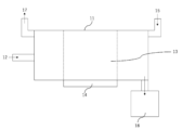
- FIG. 1 is a schematic diagram of a reaction vessel for explaining the production process of lithium sulfide and the lithium sulfide production section.
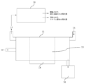
- FIG. 2 is a schematic diagram for explaining a process and an apparatus for recovering a mixed gas containing unreacted hydrogen sulfide and a lithium raw material, removing the lithium raw material, and refining hydrogen sulfide.
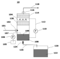
- FIG. 3 is a schematic diagram for explaining a wet spray tower and a hydrogen sulfide refining section provided in the wet spray tower.
- FIG. 4 is a schematic diagram for explaining another form of the hydrogen sulfide refining section provided in the wet spray tower.
- FIG. 5 is a schematic diagram for explaining another form of the hydrogen sulfide refining section provided in the wet spray tower.
- FIG. 6 is a schematic diagram for explaining another form of the hydrogen sulfide refining section provided in the wet spray tower.
- a method for purifying hydrogen sulfide according to one aspect of the present invention is to extract the lithium raw material from a mixed gas containing unreacted hydrogen sulfide and a lithium raw material, which is produced in the process of producing lithium sulfide by reacting hydrogen sulfide and a lithium raw material. characterized by removing
- the hydrogen sulfide refining apparatus of one aspect of the present invention includes a lithium sulfide generation unit that generates lithium sulfide by reacting hydrogen sulfide and a lithium raw material, and unreacted hydrogen sulfide and lithium raw material in the lithium sulfide generation unit. and a hydrogen sulfide refining unit for refining hydrogen sulfide by removing lithium raw materials from the mixed gas.
- lithium sulfide utilizes a sulfurization reaction between a lithium raw material and hydrogen sulfide gas, and this sulfurization reaction can be represented, for example, by the following formulas (1) to (3).
- this sulfurization reaction can be represented, for example, by the following formulas (1) to (3).
- LiOH is described as a lithium raw material in the following formula (1), the present invention is not limited to this form.
- unreacted hydrogen sulfide does not participate in the sulfurization reaction represented by the above formulas (1) to (3). It means residual unreacted hydrogen sulfide.
- the lithium raw material is meant to include lithium sulfide (Li 2 S) and other lithium compounds generated in the process of producing lithium sulfide.
- the lithium raw material is continuously or discontinuously supplied into the heated reaction vessel, and the lithium raw material is moved in a certain direction in the reaction vessel.
- the lithium sulfide production process and the lithium sulfide generation unit continuously or non-continuously supply hydrogen sulfide gas into the reaction vessel, and react the lithium raw material with the hydrogen sulfide gas to continuously produce lithium sulfide. manufactured continuously or discontinuously.
- Hydrogen sulfide generally reacts as hydrogen sulfide gas with a lithium raw material to produce lithium sulfide.
- the hydrogen sulfide gas may be a gas consisting only of hydrogen sulfide, or a gas containing hydrogen sulfide as a main component and other gas components.
- the main component means the component with the highest content in the gas, and is, for example, 50 vol % or more.
- hydrogen sulfide gas in order to suppress a rapid sulfurization reaction, for example, hydrogen sulfide gas may be mixed with an inert gas to lower the hydrogen sulfide partial pressure.
- the concentration of hydrogen sulfide gas is preferably 10 to 100 vol%.
- the hydrogen sulfide gas concentration of 100 vol % means a gas consisting only of hydrogen sulfide gas, that is, a pure gas. Moreover, when it is less than 100 vol %, it means a mixed gas of hydrogen sulfide gas, an inert gas such as Ar or nitrogen, or a reducing gas such as hydrogen.
- the hydrogen sulfide gas concentration is preferably 10 vol% to 100 vol% from the viewpoint of maintaining an appropriate gas flow rate in the reaction tank while maintaining reactivity with the lithium raw material. Above all, the hydrogen sulfide gas concentration is more preferably 20 vol% or more and 90 vol% or less, and among these, 30 vol% or more and 80 vol% or less is even more preferable.
- Lithium raw material is a raw material that becomes a lithium source of lithium sulfide, and examples thereof include lithium hydroxide, lithium carbonate, and lithium oxide. Among them, lithium hydroxide is preferable from the viewpoint that a sulfurization reaction occurs at a low temperature and that it is excellent in stability.
- the lithium raw material When the lithium raw material is sufficiently heated and comes into contact with hydrogen sulfide gas, the above reaction will proceed further. At this time, the lithium raw material is preferably heated to a temperature range in which the lithium raw material does not melt.
- reaction tank is equipment that provides a space for the reaction between the lithium raw material and the hydrogen sulfide gas, and its shape and size are arbitrary.
- the outer shape of the reaction vessel may be any shape such as a rectangular parallelepiped shape, a columnar shape, or a polygonal columnar shape.
- the reaction tank may be equipped with a stirrer such as a stirring blade for accelerating the reaction between the lithium raw material and the hydrogen sulfide gas.
- Heating of reaction vessel In the step of producing lithium sulfide, it is preferable to heat the inside of the reaction vessel, particularly the portion with which the moving lithium sulfide comes into contact, and heat the lithium raw material moving inside the reaction vessel. A sufficiently heated lithium raw material can be brought into contact with hydrogen sulfide gas to accelerate the sulfurization reaction.
- FIG. 1 is a schematic diagram of a reaction tank 11 for explaining the lithium sulfide production process and the lithium sulfide production section.
- the heating of the reaction vessel 11 it is preferable to heat the intermediate region 13 of the reaction vessel 11 by the heating means 14 when viewed in the direction in which the lithium raw material 12 moves.
- the intermediate region 13 in the reaction vessel 11 is the area where the reaction vessel 11 is directly heated. 13, that is, the upstream region and the downstream region, specifically, the temperature of the inner wall surface of the reaction vessel 11 in that region can be set as a heating region in which the temperature is heated to 100° C. or higher. Note that the left side in FIG. 1 is the upstream side, and the right side is the downstream side.
- the temperature of the inner wall surface of the reaction vessel 11 in the intermediate region 13 is preferably 200°C to 450°C, and particularly preferably 300°C or higher or 450°C or lower.
- the temperature of the inner wall surface of the reaction vessel 11 in the intermediate region 13 can be considered to be approximately the same temperature as the material temperature of the lithium raw material 12, if the inner wall surface of the reaction vessel 11 in the intermediate region 13 is 200 ° C. to 450 ° C., the above Sulfurization reaction can be sufficiently accelerated.
- the direction in which the lithium source material 12 is moved in the reaction tank 11 is arbitrary, such as the horizontal direction, the vertical up-down direction, the rotation direction, the rotation axis direction, and the length direction of the reaction tank 11 .
- the lithium source 12 can be moved along the length of the reaction vessel 11 .
- Hydrogen sulfide 15 can be made to flow.
- the moving direction of the hydrogen sulfide 15 may be the same as the moving direction of the lithium raw material 12 .
- the flow rate of the hydrogen sulfide 15 in the reaction tank 11 is arbitrary.
- the hydrogen sulfide 15 is preferably supplied into the reaction vessel 11 .
- the supply position of the hydrogen sulfide 15 may be provided in the heating region (upstream side) or the intermediate region 13.
- the exhausted unreacted hydrogen sulfide gas can be recovered as elemental sulfur by the Claus method.
- the discharged unreacted hydrogen sulfide gas contains finely powdered lithium raw material, and the lithium raw material poisons the Claus catalyst and is present together with moisture. There was a problem of corroding metal pipes and the like.
- one aspect of the present invention is characterized by comprising a process and an apparatus for recovering a mixed gas containing unreacted hydrogen sulfide and a lithium raw material, removing the lithium raw material, and refining hydrogen sulfide. Specific methods and means are described below.
- Lithium sulfide (Li 2 S), which is the main product produced by the sulfurization reaction, is preferably moved downstream and recovered in a lithium sulfide recovery tank 18, as shown in FIG.
- lithium sulfide Li 2 S
- the moisture in the lithium sulfide recovery tank 18 can be vaporized and not exist as water (liquid).
- the moisture in the lithium sulfide recovery tank 18 can be volatilized, and the collected lithium sulfide can be prevented from agglomerating or adhering to the inner wall surface of the lithium sulfide recovery tank 18.
- an inert gas may be supplied into the lithium sulfide recovery tank 18.
- moisture can be discharged out of the lithium sulfide recovery tank 18 together with the inert gas.
- FIG. 2 is a schematic diagram for explaining the process and apparatus for recovering a mixed gas containing unreacted hydrogen sulfide and a lithium raw material, removing the lithium raw material, and refining hydrogen sulfide.
- a mixed gas containing unreacted hydrogen sulfide gas and a lithium raw material exhausted from the lithium sulfide production process and the lithium sulfide generation unit described in FIG. 1 is recovered in a wet spray tower 10 and wet sprayed
- a hydrogen sulfide refining section provided in the tower 10 removes the lithium raw material from the mixed gas to purify hydrogen sulfide.
- FIG. 3 is a schematic diagram for explaining the wet spray tower 10 and the hydrogen sulfide refining unit provided in the wet spray tower 10.
- FIG. 3 is a schematic diagram for explaining the wet spray tower 10 and the hydrogen sulfide refining unit provided in the wet spray tower 10.
- the wet spray tower 10 includes a mixed gas inlet 102, a venturi section 103, a spray member 104, a cleaning liquid tank 105 containing a cleaning liquid, a demister 114, a gas outlet 116 for discharging purified hydrogen sulfide gas, It mainly includes a lithium raw material tank 120 that stores the recovered lithium raw material.
- a mixed gas 101 containing unreacted hydrogen sulfide gas and a lithium raw material exhausted from the lithium sulfide production process and the lithium sulfide generation unit described in FIG. be done.
- the mixed gas temperature is preferably adjusted to 100 to 220° C., more preferably 140 to 180° C. (In the following example, the mixed gas temperature was adjusted to 160° C. ).
- the mixed gas temperature was adjusted to 100° C. or higher, condensation of water in the wet spray tower 10 can be suppressed, and by setting the temperature to 220° C. or lower, the cost of the components of the wet spray tower 10 can be suppressed. can be done.
- the mixed gas 101 is sprayed with the cleaning liquid 108, the cleaning liquid 108 is brought into contact with the mixed gas 101, and the lithium raw material is removed from the mixed gas 101.
- the wet spray tower 10 may include means for reducing the droplet size of the cleaning liquid 108 when the cleaning liquid 108 is brought into contact with the mixed gas 101 . By reducing the droplet size of the cleaning liquid 108, the frequency of contact between the lithium raw material in the mixed gas 101 and the cleaning liquid 108 increases, and the lithium raw material can be removed efficiently.
- Means for reducing the droplet size of the cleaning liquid 108 include, for example, means for increasing the flow velocity of the mixed gas 101 .
- means for increasing the flow velocity of the mixed gas 101 there is a venturi section 103 shown in FIG.
- the mixed gas 101 increases the flow velocity in the venturi section 103 , and the shear force between the mixed gas 101 and the cleaning liquid 108 reduces the droplet size of the cleaning liquid 108 .
- the contact frequency between the lithium raw material in the mixed gas 101 and the cleaning liquid 108 increases, and the lithium raw material can be removed efficiently.
- the spray member 104 sprays the cleaning liquid 108 onto the mixed gas 101 whose flow rate has been increased in the venturi section 103 .
- the cleaning liquid 108 contacts the mixed gas 101 in a state where the mixed gas 101 with an increased flow rate causes the droplet size to become finer.
- the cleaning liquid 108 is stored at the bottom of the wet spray tower 10 , pumped up by the pump 110 , and reaches the spray member 104 through the first cleaning liquid pipe 112 .
- the cleaning liquid 108 is stored in a cleaning liquid tank 105 installed outside the wet spray tower 10 , is pumped up by a pump 106 , and reaches the bottom of the wet spray tower 10 via a second cleaning liquid pipe 107 .
- the cleaning liquid 108 at the bottom of the wet spray tower 10 has its pH controlled by a pH meter 109 .
- the cleaning liquid 108 is not particularly limited as long as it can remove the lithium raw material.
- “removal” may be removal by dissolving the lithium raw material, or removal by dropping the lithium raw material with a washing liquid. Among them, removal by dissolving the lithium raw material is preferable.
- Examples of the cleaning liquid 108 include a fluid containing hydrogen sulfide, water containing hydrogen sulfide, and an organic solvent containing hydrogen sulfide.
- the hydrogen sulfide-containing water is preferably a hydrogen sulfide saturated aqueous solution. Further, the pH of the hydrogen sulfide-containing water is adjusted to preferably 9 or less, more preferably 4-9, and still more preferably 4-7. As a result, the amount of hydrogen sulfide used can be reduced, and the lithium raw material can be effectively dissolved and removed.
- Calcium chloride can also be added to the cleaning liquid 108 . According to this form, the water content in the purified hydrogen sulfide gas can be reduced.
- the concentration of calcium chloride in the cleaning liquid 108 is preferably 5-40% by mass, more preferably 15-40% by mass.
- the water concentration in the hydrogen sulfide gas can be reduced to, for example, 6% by mass or less.
- the mixed gas from which the lithium raw material has been removed may pass through a demister 114 to capture moisture in the hydrogen sulfide gas.
- a known demister can be used as the demister 114, and is not particularly limited.
- the hydrogen sulfide gas that has passed through the demister 114, that is, the refined hydrogen sulfide gas 118 passes through the gas outlet 116 and is stored in a refined hydrogen sulfide gas storage unit (not shown) provided outside the wet spray tower 10.
- the water concentration of the purified hydrogen sulfide gas 118 is preferably 10% by mass or less, more preferably 8% by mass or less.
- the dissolved and removed lithium raw material is stored in the lithium raw material tank 120 via the valve 124 and the pipe 126 (reference numeral 122).
- the refined hydrogen sulfide gas and the recovered lithium raw material can be supplied to the lithium sulfide generation unit and reused in the lithium sulfide manufacturing process as shown in FIG.
- this step of producing lithium sulfide only the refined hydrogen sulfide gas and the recovered lithium raw material may be used, or the hydrogen sulfide gas and the lithium raw material may be additionally mixed and used.
- a lithium sulfide generating section for reacting hydrogen sulfide and a lithium raw material to generate lithium sulfide, and a mixture containing unreacted hydrogen sulfide and lithium raw material in the lithium sulfide generating section.
- a mixed gas recovery unit for recovering gas, a hydrogen sulfide refining unit for refining hydrogen sulfide by removing lithium raw materials from the mixed gas, and supplying hydrogen sulfide obtained in the hydrogen sulfide refining unit to the lithium sulfide generation unit. and a hydrogen sulfide supply unit.
- a lithium sulfide generation unit that generates lithium sulfide by reacting hydrogen sulfide and a lithium raw material
- a mixed gas recovery unit that recovers a mixed gas containing unreacted hydrogen sulfide and lithium raw material in the lithium sulfide generation unit.
- a hydrogen sulfide refining unit that removes the lithium raw material from the mixed gas to refine hydrogen sulfide; and a lithium raw material supply unit that supplies the lithium raw material recovered by the hydrogen sulfide refining unit to the lithium sulfide generation unit.
- FIG. 3 are the same as those of the wet spray tower 10 shown in FIG. 3, so description thereof will be omitted.
- FIG. 4 shows a form in which the packed bed 128 is newly installed without providing the venturi section 103 in the wet spray tower 10 shown in FIG.
- the filling layer 128 is provided for the purpose of increasing the frequency of contact between the mixed gas 101 and the cleaning liquid 108 .
- the filling layer 128 is filled with polypropylene filler.
- FIG. 5 shows a form in which the venturi section 103 is not provided in the wet spray tower 10 shown in FIG.
- FIG. 6 shows a configuration in which the demister 114 is not provided in the wet spray tower 10 shown in FIG.
- FIGS. 3 to 6 an embodiment in which a cleaning liquid is sprayed into the mixed gas as a means for removing the lithium raw material from the mixed gas has been described as an example, but in the present invention, unreacted hydrogen sulfide and as a means for removing the lithium raw material from the mixed gas containing the lithium raw material, the mixed gas is brought into contact with an amine solution, hydrogen sulfide in the mixed gas is absorbed in the amine solution, and hydrogen sulfide is removed from the amine solution that has absorbed hydrogen sulfide. may be released.
- a technique for absorbing hydrogen sulfide into an amine solution is known as the Carbotol method, which is disclosed, for example, in Japanese Patent No. 6204465.
- Hydrogen sulfide can be recovered by heating the amine solution (eg, heating at 116-127°C).
- Example 1 (Production of lithium sulfide) The apparatus shown in FIG. 1 was used to produce lithium sulfide. Lithium hydroxide having an average particle size of 200 ⁇ m was used as the lithium raw material, and the temperature of the inner wall surface of the reactor (rotary kiln) in the intermediate region was set to 300°C. While continuously supplying the lithium raw material into the reaction vessel and moving the lithium raw material from upstream to downstream in the reaction vessel, hydrogen sulfide gas was continuously supplied into the reaction vessel on the downstream side of the lithium raw material. . In the reactor, the reaction between the hydrogen sulfide gas and the lithium raw material was promoted by stirring (with stirring blades).
- a mixed gas containing unreacted hydrogen sulfide and lithium raw material was generated, which was collected in a wet spray tower 10 as shown in FIG.
- a hydrogen sulfide refining unit provided in the wet spray tower 10 removed the lithium raw material from the mixed gas to refine hydrogen sulfide.
- the lithium compound concentration (LiOH, Li 2 S, etc.) in the mixed gas was measured by the method described in JIS Z8808 2013 and found to be 25 ⁇ g/Nm 3 .
- the wet spray tower 10 one having the configuration shown in FIG. 3 was adopted.
- the introduction temperature of the mixed gas 101 into the wet spray tower 10 was 160°C.
- a saturated aqueous solution of hydrogen sulfide having a pH of 4.5 was used as the cleaning liquid 108 .
- the mixed gas 101 introduced into the wet spray tower 10 has its flow velocity increased by the venturi section 103 , and the washing liquid 108 is sprayed by the spray member 104 .
- the mixed gas from which the lithium raw material has been removed passes through a demister 114 to capture moisture in the hydrogen sulfide gas and obtain a purified hydrogen sulfide gas 118 .
- the gas 118 was stored in a not-shown purified hydrogen sulfide gas storage unit provided outside the wet spray tower 10 through a gas discharge port 116 .
- the purified hydrogen sulfide gas 118 had a water concentration of 8% by mass and a lithium compound concentration of less than 1 ⁇ g/Nm 3 .
- Example 2 In Example 1, Example 1 was repeated except that the above “with stirring blade” was changed to "without stirring blade”. Table 1 shows the results.
- Example 3 Example 1 was repeated except that the wet spray tower 10 shown in FIG. 5 without the venturi section 103 was used. Table 1 shows the results.
- Example 4 Example 1 was repeated except that the wet spray tower 10 shown in FIG. Table 1 shows the results.
- Example 1 was repeated except that in Example 1 the wet spray tower 10 shown in FIG. Table 1 shows the results.
- Example 6 Example 1 was repeated, except that calcium chloride was added to the cleaning liquid 108 to a concentration of 30% by weight. Table 1 shows the results.
- Example 7 Example 1 was repeated, except that the spray member 104 did not spray the cleaning liquid 108 . Table 1 shows the results. In addition, in Example 7, since the cleaning liquid was not sprayed, the lithium compound concentration of the gas that passed through the wet spray tower 10 was not measured.
- Example 8 In Example 7, Example 1 was repeated except that the above “with stirring blade” was changed to "without stirring blade”. Table 1 shows the results. In addition, in Example 8, since the cleaning liquid was not sprayed, the lithium compound concentration of the gas that passed through the wet spray tower 10 was not measured.
Landscapes
- Chemical & Material Sciences (AREA)
- Organic Chemistry (AREA)
- Inorganic Chemistry (AREA)
- Treating Waste Gases (AREA)
- General Physics & Mathematics (AREA)
- Condensed Matter Physics & Semiconductors (AREA)
- Physics & Mathematics (AREA)
- Engineering & Computer Science (AREA)
- Manufacturing & Machinery (AREA)
- Chemical Kinetics & Catalysis (AREA)
- Electrochemistry (AREA)
- General Chemical & Material Sciences (AREA)
- Gas Separation By Absorption (AREA)
Abstract
Description
2LiOH+H2S →Li2S+2H2O (1)
Li2CO3+H2S →Li2S+H2O+CO2 (2)
Li2O+H2S →Li2S+H2O (3)
反応炉: 3H2S+3/2O2 →2H2S+SO2+H2O (i)
触媒床: 2H2S+SO2 →3S+2H2O (ii)
(1)硫化水素とリチウム原料との反応により硫化リチウムを製造する過程で生じる、未反応の硫化水素およびリチウム原料を含有する混合ガスから、前記リチウム原料を除去する、硫化水素の精製方法。
(2)前記混合ガスに洗浄液を接触させ、前記混合ガスから前記リチウム原料を除去する、前記(1)に記載の硫化水素の精製方法。
(3)前記洗浄液は硫化水素を含有する、前記(2)に記載の硫化水素の精製方法。
(4)前記洗浄液は塩化カルシウムを含有する、前記(2)または(3)に記載の硫化水素の精製方法。
(5)前記洗浄液のpHが4~9である、前記(2)~(4)のいずれか1に記載の硫化水素の精製方法。
(6)前記洗浄液の液滴サイズを細かくする手段を備える、前記(2)~(5)のいずれか1に記載の硫化水素の精製方法。
(7)前記混合ガスの流速を増加させ、前記混合ガスと洗浄液との間のせん断力で、前記洗浄液の液滴サイズを細かくする、前記(6)に記載の硫化水素の精製方法。
(8)前記リチウム原料が除去された前記混合ガス中の水分が10質量%以下である、前記(2)~(7)のいずれか1に記載の硫化水素の精製方法。
(9)前記混合ガスにアミン溶液を接触させ、前記混合ガス中の硫化水素を前記アミン溶液中に吸収させ、前記硫化水素を吸収した前記アミン溶液から硫化水素を放出させる、前記(1)に記載の硫化水素の精製方法。
(10)前記(1)~(9)のいずれか1に記載の硫化水素の精製方法によって得られた硫化水素を含む硫化水素を、リチウム原料と反応させ硫化リチウムを製造する、硫化リチウムの製造方法。
(11)前記(1)~(9)のいずれか1に記載された硫化水素の精製方法によって回収されたリチウム原料を含むリチウム原料を、硫化水素と反応させ硫化リチウムを製造する、硫化リチウムの製造方法。
(12)硫化水素とリチウム原料とを反応させて硫化リチウムを生成する、硫化リチウム生成部と、
前記硫化リチウム生成部内の未反応の硫化水素およびリチウム原料を含有する混合ガスを回収する、混合ガス回収部と、
前記混合ガスからリチウム原料を除去し硫化水素を精製する、硫化水素精製部と、
を備える硫化水素精製装置。
(13)硫化水素とリチウム原料とを反応させて硫化リチウムを生成する、硫化リチウム生成部と、
前記硫化リチウム生成部内の未反応の硫化水素およびリチウム原料を含有する混合ガスを回収する、混合ガス回収部と、
前記混合ガスからリチウム原料を除去し硫化水素を精製する、硫化水素精製部と、
前記硫化水素精製部で得られた硫化水素を前記硫化リチウム生成部へ供給する、硫化水素供給部と、
を備える硫化リチウム製造装置。
Li2CO3+H2S →Li2S+H2O+CO2 (2)
Li2O+H2S →Li2S+H2O (3)
硫化水素は、通常硫化水素ガスとしてリチウム原料と反応し、硫化リチウムを生成する。硫化水素ガスは、硫化水素のみからなるガスであってもよいし、硫化水素を主成分としつつ他のガス成分を含有するガスであってもよい。ここで、主成分とは、当該ガス中で最も含有量の多い成分を意味し、例えば、50vol%以上である。本発明の一態様において、急激に硫化反応が起こるのを抑制するため、例えば、硫化水素ガスに不活性ガスを混合して硫化水素分圧を下げるようにしてもよい。
リチウム原料は、硫化リチウムのリチウム源となる原料のことであって、例えば水酸化リチウム、炭酸リチウム、酸化リチウムなどが挙げられる。中でも、低温にて硫化反応が起こると共に、安定性に優れている観点から、水酸化リチウムが好ましい。
反応槽内に供給されたリチウム原料と硫化水素ガスとが接触すると、前記式(1)~(3)等の硫化反応が生じ、主生成物である硫化リチウム(Li2S)と、副生成物である水(H2O)などが生成する。
反応槽は、リチウム原料と硫化水素ガスとが反応する空間を提供する設備であり、その形状及び大きさは任意である。反応槽の外形形状は、直方体状、円柱状、多角柱状など任意である。反応槽は、リチウム原料と硫化水素ガスとの反応を促進する攪拌翼等の撹拌機を備えてもよい。
前記硫化リチウムの製造工程では、反応槽内、特に移動中の硫化リチウムが接触する部分を加熱し、反応槽内を移動するリチウム原料を加熱するのが好ましい。十分加熱された状態のリチウム原料を硫化水素ガスと接触させ前記硫化反応を促進させることができる。
前記硫化リチウムの製造工程および硫化リチウム生成部では、図1に示すように、リチウム原料12を反応槽11内に連続的に供給すると共に、反応槽11内において一定方向にリチウム原料12を移動させることができる。
図1に示す形態の前記硫化リチウムの製造工程および硫化リチウム生成部では、上記硫化水素15を反応槽11内に連続的に供給する。
前記硫化リチウムの製造工程および硫化リチウム生成部では、図1に示すように、上記硫化反応によって生成した副生成物である水蒸気(H2O)及び二酸化炭素(CO2)、さらには未反応の硫化水素ガスなどを、反応槽11の外に排気17する。
上記硫化反応によって生成した主生成物である硫化リチウム(Li2S)は、図1に示すように、下流側に移動させて硫化リチウム回収槽18内に回収するのが好ましい。
図1で説明した前記硫化リチウムの製造工程および硫化リチウム生成部から排気された未反応の硫化水素ガスおよびリチウム原料を含有する混合ガス101は、混合ガス導入口102から湿式スプレー塔10内に導入される。
(硫化リチウムの製造)
図1に示す装置を用いて硫化リチウムの製造を行った。
リチウム原料として平均粒径が200μmの水酸化リチウムを用い、中間領域の反応槽(ロータリーキルン)内壁面温度を300℃に設定した。
リチウム原料を反応槽内に連続的に供給すると共に、反応槽内において上流から下流方向にリチウム原料を移動させながら、リチウム原料よりも下流側で硫化水素ガスを反応槽内に連続的に供給した。反応槽内では、攪拌を行うことで硫化水素ガスとリチウム原料との反応を促進させた(攪拌翼あり)。
上記工程により、未反応の硫化水素およびリチウム原料を含有する混合ガスが発生し、これを図2に示すように湿式スプレー塔10に回収した。湿式スプレー塔10に設けられた硫化水素精製部によって、混合ガスからリチウム原料を除去し、硫化水素を精製した。なお、混合ガス中のリチウム化合物濃度(LiOH、Li2S等)をJIS Z8808 2013記載の方法によって測定したところ、25μg/Nm3であった。
湿式スプレー塔10への混合ガス101の導入温度は160℃とした。
洗浄液108として、pH4.5の硫化水素飽和水溶液を用いた。
湿式スプレー塔10内に導入された混合ガス101は、ベンチュリー部103により流速が増加せしめられ、スプレー部材104によって洗浄液108が噴霧された。
続いて、リチウム原料が除去された混合ガスは、デミスター114を通過し、硫化水素ガス中の水分が捕獲され、精製された硫化水素ガス118を得た。該ガス118は、ガス排出口116を経て、湿式スプレー塔10の外部に設けられた図示しない精製硫化水素ガス収容部に収容された。精製された硫化水素ガス118の水分濃度は、8質量%であり、リチウム化合物濃度は1μg/Nm3未満であった。
また、精製された硫化水素ガス118をクラウス法により硫黄回収したところ、硫黄生成効率に変化なく、触媒への被毒は確認されなかった。
例1において、上記「撹拌翼あり」を「撹拌翼なし」に変更したこと以外は、例1を繰り返した。結果を表1に示す。
例1において、ベンチュリー部103を設けない図5に示す湿式スプレー塔10を用いたこと以外は、例1を繰り返した。結果を表1に示す。
例1において、充填層128を設けた図4に示す湿式スプレー塔10を用いたこと以外は、例1を繰り返した。結果を表1に示す。
例1において、デミスター114を設けない図6に示す湿式スプレー塔10を用いたこと以外は、例1を繰り返した。結果を表1に示す。
例1において、洗浄液108に塩化カルシウムを30質量%の濃度となるように添加したこと以外は、例1を繰り返した。結果を表1に示す。
例1において、スプレー部材104による洗浄液108の噴霧を行わなかったこと以外は、例1を繰り返した。結果を表1に示す。なお、例7では洗浄液の噴霧を行っていないため、湿式スプレー塔10を経たガスのリチウム化合物濃度は測定していない。
例7において、上記「撹拌翼あり」を「撹拌翼なし」に変更したこと以外は、例1を繰り返した。結果を表1に示す。なお、例8では洗浄液の噴霧を行っていないため、湿式スプレー塔10を経たガスのリチウム化合物濃度は測定していない。

11 反応槽
12 リチウム原料
13 中間領域
14 加熱手段
15 硫化水素
17 排気
18 硫化リチウム回収槽
101 混合ガス
102 混合ガス導入口
103 ベンチュリー部
104 スプレー部材
105 洗浄液タンク
106 ポンプ
107 洗浄液第2配管
108 洗浄液
109 pH計
110 ポンプ
112 洗浄液第1配管
114 デミスター
116 ガス排出口
118 硫化水素ガス
120 リチウム原料タンク
124 弁
126 配管
128 充填層
Claims (13)
- 硫化水素とリチウム原料との反応により硫化リチウムを製造する過程で生じる、未反応の硫化水素およびリチウム原料を含有する混合ガスから、前記リチウム原料を除去する、
硫化水素の精製方法。 - 前記混合ガスに洗浄液を接触させ、前記混合ガスから前記リチウム原料を除去する、請求項1に記載の硫化水素の精製方法。
- 前記洗浄液は硫化水素を含有する、請求項2に記載の硫化水素の精製方法。
- 前記洗浄液は塩化カルシウムを含有する、請求項2または3に記載の硫化水素の精製方法。
- 前記洗浄液のpHが4~9である、請求項2~4のいずれか1項に記載の硫化水素の精製方法。
- 前記洗浄液の液滴サイズを細かくする手段を備える、請求項2~5のいずれか1項に記載の硫化水素の精製方法。
- 前記混合ガスの流速を増加させ、前記混合ガスと洗浄液との間のせん断力で、前記洗浄液の液滴サイズを細かくする、請求項6に記載の硫化水素の精製方法。
- 前記リチウム原料が除去された前記混合ガス中の水分が10質量%以下である、請求項2~7のいずれか1項に記載の硫化水素の精製方法。
- 前記混合ガスにアミン溶液を接触させ、前記混合ガス中の硫化水素を前記アミン溶液中に吸収させ、前記硫化水素を吸収した前記アミン溶液から硫化水素を放出させる、請求項1に記載の硫化水素の精製方法。
- 請求項1~9のいずれか1項に記載の硫化水素の精製方法によって得られた硫化水素を含む硫化水素を、リチウム原料と反応させ硫化リチウムを製造する、硫化リチウムの製造方法。
- 請求項1~9のいずれか1項に記載された硫化水素の精製方法によって回収されたリチウム原料を含むリチウム原料を、硫化水素と反応させ硫化リチウムを製造する、硫化リチウムの製造方法。
- 硫化水素とリチウム原料とを反応させて硫化リチウムを生成する、硫化リチウム生成部と、
前記硫化リチウム生成部内の未反応の硫化水素およびリチウム原料を含有する混合ガスを回収する、混合ガス回収部と、
前記混合ガスからリチウム原料を除去し硫化水素を精製する、硫化水素精製部と、
を備える硫化水素精製装置。 - 硫化水素とリチウム原料とを反応させて硫化リチウムを生成する、硫化リチウム生成部と、
前記硫化リチウム生成部内の未反応の硫化水素およびリチウム原料を含有する混合ガスを回収する、混合ガス回収部と、
前記混合ガスからリチウム原料を除去し硫化水素を精製する、硫化水素精製部と、
前記硫化水素精製部で得られた硫化水素を前記硫化リチウム生成部へ供給する、硫化水素供給部と、
を備える硫化リチウム製造装置。
Priority Applications (4)
| Application Number | Priority Date | Filing Date | Title |
|---|---|---|---|
| EP21959502.2A EP4410741A4 (en) | 2021-09-30 | 2021-12-08 | HYDROGEN SULFIDE PURIFICATION PROCESS, LITHIUM SULFIDE PRODUCTION PROCESS, HYDROGEN SULFIDE PURIFICATION DEVICE AND LITHIUM SULFIDE PRODUCTION DEVICE |
| CN202180102865.7A CN118043281A (zh) | 2021-09-30 | 2021-12-08 | 硫化氢的纯化方法、硫化锂的制造方法、硫化氢纯化装置和硫化锂制造装置 |
| KR1020247009848A KR20240065255A (ko) | 2021-09-30 | 2021-12-08 | 황화수소의 정제 방법, 황화리튬의 제조 방법, 황화수소 정제 장치 및 황화리튬 제조 장치 |
| US18/616,291 US20240270575A1 (en) | 2021-09-30 | 2024-03-26 | Hydrogen sulfide purification method, lithium sulfide production method, hydrogen sulfide purification device, and lithium sulfide production device |
Applications Claiming Priority (2)
| Application Number | Priority Date | Filing Date | Title |
|---|---|---|---|
| JP2021161521A JP7120424B1 (ja) | 2021-09-30 | 2021-09-30 | 硫化水素の精製方法、硫化リチウムの製造方法、硫化水素精製装置および硫化リチウム製造装置 |
| JP2021-161521 | 2021-09-30 |
Related Child Applications (1)
| Application Number | Title | Priority Date | Filing Date |
|---|---|---|---|
| US18/616,291 Continuation US20240270575A1 (en) | 2021-09-30 | 2024-03-26 | Hydrogen sulfide purification method, lithium sulfide production method, hydrogen sulfide purification device, and lithium sulfide production device |
Publications (1)
| Publication Number | Publication Date |
|---|---|
| WO2023053468A1 true WO2023053468A1 (ja) | 2023-04-06 |
Family
ID=82850946
Family Applications (1)
| Application Number | Title | Priority Date | Filing Date |
|---|---|---|---|
| PCT/JP2021/045221 Ceased WO2023053468A1 (ja) | 2021-09-30 | 2021-12-08 | 硫化水素の精製方法、硫化リチウムの製造方法、硫化水素精製装置および硫化リチウム製造装置 |
Country Status (6)
| Country | Link |
|---|---|
| US (1) | US20240270575A1 (ja) |
| EP (1) | EP4410741A4 (ja) |
| JP (2) | JP7120424B1 (ja) |
| KR (1) | KR20240065255A (ja) |
| CN (1) | CN118043281A (ja) |
| WO (1) | WO2023053468A1 (ja) |
Families Citing this family (3)
| Publication number | Priority date | Publication date | Assignee | Title |
|---|---|---|---|---|
| WO2025206362A1 (ja) * | 2024-03-28 | 2025-10-02 | 出光興産株式会社 | 硫化リチウムの製造方法 |
| KR20260024419A (ko) * | 2024-08-08 | 2026-02-23 | 주식회사 레이크테크놀로지 | 황화리튬 제조 장치 |
| KR102936678B1 (ko) * | 2025-05-09 | 2026-03-10 | 주식회사 에코프로이노베이션 | 고순도 황화리튬 연속 제조방법 및 황화리튬의 연속 제조 장치 |
Citations (8)
| Publication number | Priority date | Publication date | Assignee | Title |
|---|---|---|---|---|
| JPH0656408A (ja) * | 1992-08-07 | 1994-03-01 | Idemitsu Eng Co Ltd | 水硫化ソーダの製造方法 |
| JP2000247609A (ja) * | 1999-02-25 | 2000-09-12 | Idemitsu Petrochem Co Ltd | 無水アルカリ金属硫化物の製造方法 |
| JP2014001091A (ja) * | 2012-06-15 | 2014-01-09 | Idemitsu Kosan Co Ltd | アルカリ金属硫化物の製造方法 |
| JP2015524350A (ja) * | 2012-06-29 | 2015-08-24 | ダウ グローバル テクノロジーズ エルエルシー | ガス混合物からの硫化水素の除去が促進された、ピペラジンを含む水性アルカノール吸収剤組成物、及びその使用方法 |
| JP2016150859A (ja) | 2015-02-16 | 2016-08-22 | 古河機械金属株式会社 | 硫化リチウム粒子、硫化物系無機固体電解質材料および硫化物系正極活物質 |
| JP2017222567A (ja) | 2016-06-14 | 2017-12-21 | 出光興産株式会社 | 硫化リチウム、及びその製造方法 |
| JP2020033259A (ja) * | 2019-10-30 | 2020-03-05 | 古河機械金属株式会社 | 硫化リチウムの製造装置 |
| JP2021161521A (ja) | 2020-04-02 | 2021-10-11 | トヨタ自動車株式会社 | 部品の支持構造 |
Family Cites Families (6)
| Publication number | Priority date | Publication date | Assignee | Title |
|---|---|---|---|---|
| US8084160B2 (en) * | 2003-10-23 | 2011-12-27 | Idemitsu Kosan Co., Ltd. | Method for purifying lithium sulfide |
| JP5062262B2 (ja) * | 2009-03-16 | 2012-10-31 | トヨタ自動車株式会社 | 電池部材の処理方法 |
| JP6414674B2 (ja) * | 2014-08-04 | 2018-10-31 | 東レ・ファインケミカル株式会社 | 硫化リチウムの製造方法 |
| JP6612145B2 (ja) * | 2016-02-09 | 2019-11-27 | 古河機械金属株式会社 | 硫化リチウムの製造方法 |
| JP6718774B2 (ja) * | 2016-09-01 | 2020-07-08 | 三井金属鉱業株式会社 | 硫化リチウムの製造方法及び製造装置 |
| CN108059176B (zh) * | 2017-12-27 | 2019-08-30 | 江西赣锋锂业股份有限公司 | 一种利用硫化锂废料制备工业级碳酸锂的方法 |
-
2021
- 2021-09-30 JP JP2021161521A patent/JP7120424B1/ja active Active
- 2021-12-08 KR KR1020247009848A patent/KR20240065255A/ko active Pending
- 2021-12-08 EP EP21959502.2A patent/EP4410741A4/en active Pending
- 2021-12-08 CN CN202180102865.7A patent/CN118043281A/zh active Pending
- 2021-12-08 WO PCT/JP2021/045221 patent/WO2023053468A1/ja not_active Ceased
-
2022
- 2022-08-03 JP JP2022124196A patent/JP7363991B2/ja active Active
-
2024
- 2024-03-26 US US18/616,291 patent/US20240270575A1/en active Pending
Patent Citations (9)
| Publication number | Priority date | Publication date | Assignee | Title |
|---|---|---|---|---|
| JPH0656408A (ja) * | 1992-08-07 | 1994-03-01 | Idemitsu Eng Co Ltd | 水硫化ソーダの製造方法 |
| JP2000247609A (ja) * | 1999-02-25 | 2000-09-12 | Idemitsu Petrochem Co Ltd | 無水アルカリ金属硫化物の製造方法 |
| JP2014001091A (ja) * | 2012-06-15 | 2014-01-09 | Idemitsu Kosan Co Ltd | アルカリ金属硫化物の製造方法 |
| JP2015524350A (ja) * | 2012-06-29 | 2015-08-24 | ダウ グローバル テクノロジーズ エルエルシー | ガス混合物からの硫化水素の除去が促進された、ピペラジンを含む水性アルカノール吸収剤組成物、及びその使用方法 |
| JP6204465B2 (ja) | 2012-06-29 | 2017-09-27 | ダウ グローバル テクノロジーズ エルエルシー | ガス混合物からの硫化水素の除去が促進された、ピペラジンを含む水性アルカノール吸収剤組成物、及びその使用方法 |
| JP2016150859A (ja) | 2015-02-16 | 2016-08-22 | 古河機械金属株式会社 | 硫化リチウム粒子、硫化物系無機固体電解質材料および硫化物系正極活物質 |
| JP2017222567A (ja) | 2016-06-14 | 2017-12-21 | 出光興産株式会社 | 硫化リチウム、及びその製造方法 |
| JP2020033259A (ja) * | 2019-10-30 | 2020-03-05 | 古河機械金属株式会社 | 硫化リチウムの製造装置 |
| JP2021161521A (ja) | 2020-04-02 | 2021-10-11 | トヨタ自動車株式会社 | 部品の支持構造 |
Non-Patent Citations (1)
| Title |
|---|
| See also references of EP4410741A4 |
Also Published As
| Publication number | Publication date |
|---|---|
| EP4410741A4 (en) | 2025-11-05 |
| JP7120424B1 (ja) | 2022-08-17 |
| EP4410741A1 (en) | 2024-08-07 |
| CN118043281A (zh) | 2024-05-14 |
| KR20240065255A (ko) | 2024-05-14 |
| US20240270575A1 (en) | 2024-08-15 |
| JP7363991B2 (ja) | 2023-10-18 |
| JP2023051750A (ja) | 2023-04-11 |
| JP2023051067A (ja) | 2023-04-11 |
Similar Documents
| Publication | Publication Date | Title |
|---|---|---|
| JP7363991B2 (ja) | 硫化水素の精製方法、硫化リチウムの製造方法、硫化水素精製装置および硫化リチウム製造装置 | |
| TWI740458B (zh) | 一種氮氧化物吸收劑漿液及其製備和使用方法 | |
| US4406867A (en) | Process for the purification of non-reacting gases | |
| CN103889553B (zh) | 过氟化物的分解处理方法以及处理装置 | |
| US20250178897A1 (en) | Hydrogen sulfide purification method and lithium sulfide production method | |
| EP2758152A1 (en) | Water-saving liquid gas processing system based on equilibrium moisture operation | |
| CN108178135A (zh) | 一种脱硝固体产物的处理方法和装置 | |
| WO2024034534A1 (ja) | 硫化水素の精製方法および硫化リチウムの製造方法 | |
| JP7197223B2 (ja) | 窒素酸化物吸収剤スラリーとその調製、使用および再生方法 | |
| US3687623A (en) | Process for recovering sulfur dioxide from a gas containing same | |
| NO149989B (no) | Fremgangsmaate for rensing av ikke-reagerende gasser | |
| CA1154939A (en) | Process for the purification of nonreacting gases | |
| CN119365414A (zh) | 用于硫酸生产设备的尾气处理系统和方法 | |
| CA2309422C (en) | Hydrogen sulfide removal process | |
| JP2016019964A (ja) | ハイポフルオライトの湿式除去方法 | |
| HK40068087A (en) | Nitrogen oxide absorbent slurry, preparation method therefor and use method thereof | |
| CN114053857A (zh) | 废气处理方法以及玻璃物品的制造方法 | |
| CN116173697A (zh) | 一种锑锭生产脱硫综合处理系统 | |
| OA20300A (en) | Nitrogen oxide absorbent slurry, preparation method therefor and use method thereof. | |
| HK1215226A1 (zh) | 烟气治理装置和方法 | |
| HK1215226B (en) | Flue gas treatment device and method |
Legal Events
| Date | Code | Title | Description |
|---|---|---|---|
| 121 | Ep: the epo has been informed by wipo that ep was designated in this application |
Ref document number: 21959502 Country of ref document: EP Kind code of ref document: A1 |
|
| ENP | Entry into the national phase |
Ref document number: 20247009848 Country of ref document: KR Kind code of ref document: A |
|
| WWE | Wipo information: entry into national phase |
Ref document number: 202180102865.7 Country of ref document: CN |
|
| NENP | Non-entry into the national phase |
Ref country code: DE |
|
| ENP | Entry into the national phase |
Ref document number: 2021959502 Country of ref document: EP Effective date: 20240430 |