WO2023101009A1 - Boîte-tampon - Google Patents
Boîte-tampon Download PDFInfo
- Publication number
- WO2023101009A1 WO2023101009A1 PCT/JP2022/044552 JP2022044552W WO2023101009A1 WO 2023101009 A1 WO2023101009 A1 WO 2023101009A1 JP 2022044552 W JP2022044552 W JP 2022044552W WO 2023101009 A1 WO2023101009 A1 WO 2023101009A1
- Authority
- WO
- WIPO (PCT)
- Prior art keywords
- pair
- crimping
- mounting plates
- joining
- holes
- Prior art date
- Legal status (The legal status is an assumption and is not a legal conclusion. Google has not performed a legal analysis and makes no representation as to the accuracy of the status listed.)
- Ceased
Links
Images


Classifications
-
- B—PERFORMING OPERATIONS; TRANSPORTING
- B60—VEHICLES IN GENERAL
- B60R—VEHICLES, VEHICLE FITTINGS, OR VEHICLE PARTS, NOT OTHERWISE PROVIDED FOR
- B60R19/00—Wheel guards; Radiator guards, e.g. grilles; Obstruction removers; Fittings damping bouncing force in collisions
- B60R19/02—Bumpers, i.e. impact receiving or absorbing members for protecting vehicles or fending off blows from other vehicles or objects
- B60R19/24—Arrangements for mounting bumpers on vehicles
- B60R19/26—Arrangements for mounting bumpers on vehicles comprising yieldable mounting means
- B60R19/34—Arrangements for mounting bumpers on vehicles comprising yieldable mounting means destroyed upon impact, e.g. one-shot type
-
- B—PERFORMING OPERATIONS; TRANSPORTING
- B21—MECHANICAL METAL-WORKING WITHOUT ESSENTIALLY REMOVING MATERIAL; PUNCHING METAL
- B21J—FORGING; HAMMERING; PRESSING METAL; RIVETING; FORGE FURNACES
- B21J15/00—Riveting
- B21J15/02—Riveting procedures
-
- B—PERFORMING OPERATIONS; TRANSPORTING
- B23—MACHINE TOOLS; METAL-WORKING NOT OTHERWISE PROVIDED FOR
- B23K—SOLDERING OR UNSOLDERING; WELDING; CLADDING OR PLATING BY SOLDERING OR WELDING; CUTTING BY APPLYING HEAT LOCALLY, e.g. FLAME CUTTING; WORKING BY LASER BEAM
- B23K11/00—Resistance welding; Severing by resistance heating
- B23K11/10—Spot welding; Stitch welding
- B23K11/11—Spot welding
- B23K11/115—Spot welding by means of two electrodes placed opposite one another on both sides of the welded parts
Definitions
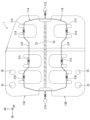
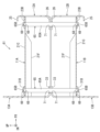
- the front side mounting plates 12A and 12B are provided with narrow reinforcing ribs 25 that are bent substantially at right angles toward the inner sides (vehicle rear side) of the opposite side edges.
- the front side mounting plates 12A and 12B are arranged such that the adjacent side edges of the front mounting plates 12A and 12B extend from the vehicle width direction outer side (the left side in FIG. 4) of the bent piece 23A to the vehicle width direction inner side (the right side in FIG. 4) of the bent piece 23B. ) is provided with a wide reinforcing rib 26 that is bent inward (vehicle rear side) at a substantially right angle.
- the width of each reinforcing rib 26 in the vehicle front-rear direction can be a substantially constant width that is substantially the same as the height of the bent pieces 23A, 23B projecting from the front mounting plates 12A, 12B.
- Through holes 27 are formed in the front mounting plates 12A and 12B at positions on the outside in the vehicle width direction of the center in the vehicle width direction and at positions on the inner edges in the vehicle width direction.
- a nut (not shown) is attached to the rear end of each through-hole 27 by arc welding, spot welding, laser welding, or the like, and is integrally assembled to the bumper reinforcement 2 by bolting.
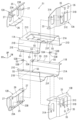
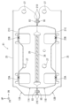
- the rear mounting plates 13A, 13B extend to approximately the center of the flanges 21D, 21E of the half bodies 11A, 11B in the vehicle width direction.
- the rear mounting plates 13A and 13B extend beyond the main body 11 in the vertical direction.
- the vertical width of the rear mounting plates 13A and 13B can be approximately twice the height from the flange portions 21D and 21E to the bottom portion 21C of the corresponding half-split bodies 11A and 11B.
- the upper rear mounting plate 13A has an outer upper edge in the vehicle width direction that is slanted downward and outward.
- the height from the respective bent pieces 31A, 31B of the rear mounting plates 13A, 13B to the reinforcing ribs 33 is equal to the vehicle vertical direction of the bottom surface portions 21C of the half bodies 11A, 11B. from the outer surface of each of the flange portions 21D and 21E to the outer surface of each of the flange portions 21D and 21E in the vertical direction of the vehicle.
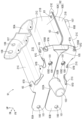
- the bent pieces 23A and 23B of the front mounting plate 12B are spot-welded to the outer surface of the bottom surface 21C of the half body 11B.
- the bent pieces 31A to 31C of the rear mounting plate 13B are spot-welded to the bottom surface 21C of the half body 11B and the outer surface of the recess 21F.
- the lower half-finished product 38 (see FIG. 6) is assembled by welding the front side mounting plate 12B and the rear side mounting plate 13B so as to cover the front side end portion and the rear side end portion of the half body 11B.
- the joints by spot welding are indicated by X marks.
- the pair of flange portions 21D and 21E of the half bodies 11A and 11B are arranged at a plurality of locations in the vehicle front-rear direction. For example, at two locations, instead of spot welding, they can be joined by a plurality of crimp pins 53 for flange joining.
- each stepped portion 53B is inserted into the joining through hole 55. It is set to protrude from the hole 55 (for example, approximately 2 mm to 5 mm).
- the rear side mounting plate 13A arranged on the upper side is brought into contact with the rear side end portion of the half body 11A, and the respective bent pieces 31A and 31B are moved to the vehicle width of the bottom portion 21C of the half body 11A. It abuts against the outer surface of both outer edges. Also, the bent piece 31C of the rear mounting plate 13A is brought into contact with the outer surface of the recess 21F formed in the bottom surface portion 21C. Further, both side edges in the vehicle width direction of the rear mounting plate 13A are opposed to substantially central portions in the vehicle width direction of the respective flange portions 21D and 21E of the half body 11A.
- the bent pieces 23A and 23B of the front mounting plate 12A are spot-welded to the outer surface of the bottom surface portion 21C of the half body 11A.
- the bent pieces 31A to 31C of the rear mounting plate 13A are spot-welded to the bottom surface 21C of the half body 11A and the outer surface of the recess 21F.
- the semi-finished product 37 (see FIG. 6) is assembled by welding the front side mounting plate 12A and the rear side mounting plate 13A so as to cover the front end portion and the rear end portion of the half body 11A.
- the joints by spot welding are indicated by x marks.
- the rear mounting plate 13B arranged on the lower side is brought into contact with the rear end portion of the half body 11B, and the bent pieces 31A and 31B are attached to the bottom portion 21C of the half body 11B. It is brought into contact with the outer side surfaces of both laterally outer edge portions. Also, the bent piece 31C of the rear mounting plate 13B is brought into contact with the outer surface of the recess 21F formed in the bottom surface portion 21C. Further, both side edges in the vehicle width direction of the rear mounting plate 13B are opposed to substantially central portions in the vehicle width direction of the respective flange portions 21D and 21E of the half body 11B.
- the bent pieces 23A and 23B of the front mounting plate 12B are spot-welded to the outer surface of the bottom surface portion 21C of the half body 11B.
- the bent pieces 31A to 31C of the rear mounting plate 13B are spot-welded to the bottom surface 21C of the half-split body 11B and the outer surface of the recess 21F.
- the semi-finished product 38 (see FIG. 6) is assembled by welding the front side mounting plate 12B and the rear side mounting plate 13B so as to cover the front side end portion and the rear side end portion of the half body 11B.
- the half-split body 11B constituting the semi-finished product 38 is arranged so that the opening side faces upward, and each jointing portion formed on the pair of flange portions 21D and 21E of the half-split body 11B is arranged.
- One step portion 53 B of the crimping pin 53 is inserted through the through hole 55 .
- the other step of the caulking pin 53 is inserted into each joining through hole 55 formed in the pair of flange portions 21D and 21E of the half-split body 11A.
- the pair of flange portions 21D and 21E of the half bodies 11A and 11B are overlapped with each other so that the portion 53B is inserted therethrough.
- the crush box 51 It is possible to prevent zinc fumes from being generated from the surface of the steel sheet, eliminate the need for a process for removing zinc fumes, and reduce manufacturing costs.
- a pair of front side mounting plates 12A, 12B, a pair of rear side mounting plates 13A, 13B, and a pair of half bodies 11A, 11B are formed by spot welding instead of spot welding.
- each stepped portion 63B is inserted through the joining through hole 73. It is set to protrude from the hole 73 (for example, approximately 2 mm to 5 mm).
- the crimping pin 65 includes a shaft portion 65A formed in the shape of a shaft that is long in the vertical direction, and a pair of steps formed coaxially with a smaller outer diameter on both ends of the shaft portion 65A in the axial direction. and a portion 65B.
- the outer diameter of the shaft portion 65A is larger than the inner diameter of the first crimping through hole 68 formed in the bottom surface portion 21C of the pair of half bodies 11A and 11B (for example, the outer diameter of the first crimping through hole 68 is larger than the inner diameter of the first crimping through hole 68). 2 mm to 7 mm larger than the inner diameter).
- first caulking through holes 68 are formed in the rear side edges of the bottom surfaces 21C of the pair of half-split bodies 11A and 11B.
- a pair of second crimping through-holes 69 through which the stepped portions 65B formed at both ends of the crimping pin 65 can be inserted are formed at positions facing the .
- the bent pieces 31C of the pair of rear mounting plates 13A and 13B face the first caulking through holes 68 formed in the rear side edges of the recesses 21F of the pair of half-split bodies 11A and 11B.
- a second crimping through-hole 69 through which the stepped portion 66B formed at both ends of the crimping pin 66 can be inserted is formed at a position.
- the reinforcing ribs 33 of the pair of rear mounting plates 13A, 13B are provided with crimping pins 65, 66 at positions facing the second crimping through holes 69 formed in the bending pieces 31A to 31C in the vertical direction.
- Three supporting through-holes 71 are formed through which the respective shaft portions 65A and 66A can be inserted.
- the crimping pin 66 includes a shaft portion 66A formed in the shape of a shaft that is long in the vertical direction, and a pair of steps that are coaxially formed at both ends of the shaft portion 66A with a small outer diameter. and a portion 66B.
- the outer diameter of the shaft portion 66A is larger than the inner diameter of the first crimping through hole 68 formed in the bottom surface portion 21C of the pair of half bodies 11A and 11B (for example, the outer diameter of the first crimping through hole 68 is larger than the inner diameter of the first crimping through hole 68). 3 mm to 7 mm larger than the inner diameter).
- the outer diameter of the shaft portion 66A is set to be substantially the same as the outer diameter of the shaft portion 65A of the crimping pin 65. As shown in FIG.
- the length of the shaft portion 66A corresponds to the length of the shaft portion 66A, which is the length of the pair of flange portions 21D and 21E of the pair of half-split bodies 11A and 11B that are mutually superimposed and are joined together by a plurality of crimping pins 63. It is formed to have a length substantially equal to the distance between the recesses 21F.
- the length of the pair of stepped portions 66B is the total thickness of the plate thickness of the bottom portion 21C of the pair of half-split bodies 11A and 11B and the plate thickness of the bent piece 31C of the pair of rear mounting plates 13A and 13B. It is set to be larger than the height (for example, approximately 2 mm to 5 mm).
- FIG. 12 to 15 As shown in FIGS. 12 to 15, first, the half-split body 11B arranged on the lower side is arranged so that the opening side faces upward. Then, the front mounting plate 12B arranged on the lower side is brought into contact with the front end portion of the half body 11B, and the bent pieces 23A and 23B are attached to the bottom surface portion 21C of the half body 11B in the vehicle width direction. It is brought into contact with the outer surfaces of both outer edges.
- one end side of the shaft portion 65A of the crimping pin 65 is inserted into each of the pair of supporting through holes 71 formed in the reinforcing rib 26 of the front mounting plate 12B.
- the stepped portion 65B formed at the lower end portion of each shaft portion 65A is connected to the first through hole 68 for crimping formed in the bottom surface portion 21C and the second through hole for crimping formed in each of the bent pieces 23A and 23B. 69 to bring the lower end of the shaft portion 65A into contact with the inner surface of the bottom surface portion 21C.
- One of the stepped portions 63B of the crimping pin 63 is inserted into each of the joint through holes 73 formed in the pair of flange portions 21D and 21E of the half-split body 11B, and the disk portion 63A is inserted into each of the flange portions 21D and 21E. abut.
- the bent pieces 23A and 23B of the front mounting plate 12A and the bent pieces 31A to 31C of the rear mounting plate 13A are positioned on the bottom surface 21C and the outer surface of the recess 21F with respect to the half-split body 11A.
- the half body 11A with the opening facing downward is arranged directly above the half body 11B.
- the half-split body 11A, the front mounting plate 12A, and the rear mounting plate 13A with the opening facing downward are lowered integrally.
- the upper end side (the other end side) of the shaft portion 65A of the crimping pin 65 is inserted into each of the two supporting through holes 71 formed at both vehicle width direction end portions of the reinforcing rib 33 of the rear mounting plate 13B. do.
- the stepped portion 65B formed at the upper end portion of each shaft portion 65A is connected to the first through hole 68 for crimping formed in the bottom surface portion 21C and the second through hole for crimping formed in each of the bent pieces 31A and 31B. 69, and the upper end of the shaft portion 65A is brought into contact with the inner surface of the bottom portion 21C.
- a pair of overlapping flange portions 21D and 21E of each of the half bodies 11A and 11B is replaced with a crimping pin 53 for flange connection and each through hole for connection. It may be joined by bolting with a hexagon socket head bolt 83 and a nut 85 inserted through 55 .
- a hexagon socket head bolt 83 is inserted from above into each connecting through-hole 55 of a pair of overlapping flange portions 21D and 21E of each of the half bodies 11A and 11B, and bolted with a nut 85. to join.
- the crash box 81 is assembled.
- the pair of front side mounting plates 12A and 12B and the pair of rear side mounting plates 13A and 13B are mounted to the pair of half bodies 11A and 11B by spot welding.
- the pair of flange portions 21D and 21E of the bodies 11A and 11B are superimposed on each other so that they can be assembled in the same mounting direction by bolting with the hexagon socket head bolts 83 and nuts 85. As shown in FIG. As a result, it is possible to shorten the assembly time of the crash box 81 and reduce the manufacturing cost.
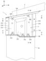
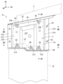
- the crash box 91 is disposed between the bumper reinforcement 2 and the side member 3L in such a posture that the axis of the body portion 92 constituting the tubular body is substantially parallel to the vehicle front-rear direction.
- 93B and a pair of rear side mounting plates 95A, 95B are integrally fixed to the bumper reinforcement 2 and the side member 3L by bolts (not shown) or the like.
- black circles indicate joints by spot welding. It should be noted that welding such as laser welding may be used instead of spot welding.
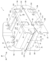
- a pair of half-split bodies 92A and 92B have substantially the same configuration as the half-split bodies 11A and 11B of FIGS.
- the half-split bodies 92A and 92B are press-formed from a steel plate so as to have a substantially hat-shaped cross section that is symmetrical in the vertical direction.
- an alloyed hot-dip galvanized steel sheet or a hot-dip galvanized steel sheet can be used, and the thickness can be about 1.0 mm to 1.6 mm, and the tensile strength can be about 590 MPa.
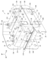
- the pair of half-split bodies 92A and 92B includes a bottom surface portion 21C (see FIG. 17) having a substantially trapezoidal shape in a plan view, and a pair of halves 92A and 92B extending from the edge of the bottom surface portion 21C and facing each other.
- a pair of vertical wall portions 21A and 21B, and a pair of flange portions 21D and 21E extending substantially parallel to the bottom portion 21C from the edges of the pair of vertical wall portions 21A and 21B, that is, the edges on the opening side of the hat shape. have.
- each crimping pin 63 is a thin plate (for example, about 1 mm to 3 mm thick) disc portion 63A and a pair of coaxially formed disc portions 63A having a small outer diameter at both ends in the axial direction of the disc portion 63A. and a stepped portion 63B.
- the side edges of the front mounting plates 93A and 93B on the inner side in the vehicle width direction extend inward in the vehicle width direction (for example, about 40 mm to 50 mm) from the vertical wall portions 21A on the inner side in the vehicle width direction of the half bodies 92A and 92B. ) is long.
- the opposite side edge portions of the pair of front mounting plates 93A and 93B are substantially perpendicular to the rear at two positions facing the bottom portions 21C on both sides in the vehicle width direction of the pair of half-split bodies 92A and 92B.
- a pair of mounting pieces 97C and 97D for caulking are provided which are substantially L-shaped when viewed from the side.
- the pair of crimping mounting pieces 97C and 97D are joined by crimping pins 65 to the outer surface of each bottom surface portion 21C.
- the length of the pair of stepped portions 65B is the sum of the plate thickness of the bottom portion 21C of the pair of half bodies 92A and 92B and the plate thickness of the crimping mounting pieces 97C and 97D of the pair of front side mounting plates 93A and 93B. It is set to be larger than the thickness (for example, approximately 2 mm to 5 mm). That is, when the stepped portion 65B is inserted through the third crimping through-hole 98 and the fourth crimping through-hole 99 and the shaft portion 65A contacts the inner surface of the bottom portion 21C, each stepped portion 65B It is set to protrude from the fourth caulking through-hole 99 (for example, about 2 mm to 5 mm).
- Each of the second supporting mounting pieces 105B is capable of inserting the shaft portion 65A of the crimping pin 65 at a position facing each of the third crimping through-holes 98 formed in the bottom portion 21C of the pair of half bodies 92A, 92B.
- 105 C of 2nd through-holes for a support are formed coaxially in the up-down direction.
- the flat plate portion 105A is formed with a through hole 105D through which the binding nut 103 is inserted from the rear side and the flange portion 103A contacts the rear end portion.
- the through holes 105D are formed at positions facing the nut insertion notches 102A and 102B of the pair of front mounting plates 93A and 93B.
- the lashing nut 103 is inserted through the through-hole 105D from the rear side in advance, and the collar portion 103A is joined to the flat plate portion 105A by arc welding, spot welding, laser welding, or the like.
- the flat plate portion 105A is formed with through holes 105E through which bolts (not shown) can be inserted, at positions facing the through holes 100 on the outer side in the vehicle width direction of the pair of front mounting plates 93A and 93B.
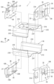
- the pair of rear mounting plates 95A and 95B decrease in height from the bottom surface portion 21C toward the outside in the vehicle width direction from the central portion in the vehicle width direction.
- the pair of rear side mounting plates 95A and 95B are configured such that the outer side portions from the substantially central portion in the vehicle width direction can contact the outer side surfaces of the rear side edge portions of the corresponding pair of half bodies 92A and 92B.
- the outside portion is bent toward the front side of the vehicle from the approximately central portion in the vehicle width direction, and is formed in a substantially crank shape in a plan view.
- the length of the pair of rear mounting plates 95A and 95B in the vehicle width direction extends from the position facing the base end of the flange portion 21D on the inner side in the vehicle width direction of the pair of half-split bodies 92A and 92B to the vehicle width of the bottom portion 21C. It is formed with a length equal to the distance to the side edge on the direction outer side.
- the vertical width of the pair of rear side mounting plates 95A and 95B is about 2/3 times the vertical height from the pair of flange portions 21D and 21E to the bottom portion 21C of the pair of half-split bodies 92A and 92B. width. Adjacent side edge portions of the pair of rear mounting plates 95A and 95B protrude in a horizontally long trapezoidal shape in a direction toward each other so as to come into contact with the outer surface of the recess 21G.
- the pair of rear side mounting plates 95A and 95B has mounting rib portions that are bent forward at approximately right angles from side edges on the inner side in the vehicle width direction to adjacent side edges. 107 are formed. As shown in FIGS. 17 and 20, each mounting rib portion 107 is provided at a position facing the bottom surface portion 21C of the pair of half-split bodies 92A and 92B and the inner edge portion of the recessed portion 21G in the vehicle width direction. It is formed to have a width dimension that allows spot welding to be performed on the bottom surface portion 21C and the recessed portion 21G that are in contact with each other.
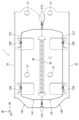
- the front side edge of the brace plate 111 has a pair of vertical wall portions 21A when the brace plate 111 is arranged between the pair of flange portions 21D and 21E.
- 21B is provided with a narrow reinforcing rib 111B bent upward at a substantially right angle over the entire length thereof. Note that the reinforcing rib 111B may be bent downward at a substantially right angle.
- the pair of crimping mounting pieces 97C and 97D of the front side mounting plate 93A are brought into contact with the outer surface of the front end portion of each bottom surface portion 21C of the half-split body 92A, and the fourth crimping mounting pieces 97C and 97D are brought into contact with each other.
- the caulking through-hole 99 and the third caulking through-hole 98 of each bottom surface portion 21C are arranged so as to communicate with each other and positioned.
- the mounting rib portion 107 of the rear mounting plate 95A arranged on the upper side is arranged along the rear side edge portion of the half body 92A so as to abut on the bottom surface portion 21C and the outer surface of the recess 21G. position.
- the welding mounting piece 97B of the front side mounting plate 93A is joined to the outer surface of the recess 21G of the half body 92A by spot welding.
- the mounting rib portion 107 of the rear mounting plate 95A is joined to the bottom surface portions 21C of the half body 92A and the outer surface of the recess 21G by spot welding.
- the front side mounting plate 93A is mounted so as to cover the front end portion of the half body 92A
- the rear mounting plate 93A is mounted so as to protrude away from each other from the outer surface of the rear side edge of the half body 92A.
- a semi-finished product 113 (see FIG. 23) is assembled to which the plate 95A is attached.
- joints by spot welding are indicated by X marks.
- One of the stepped portions 63B of the crimping pin 63 is inserted into each of the joining through holes 73 formed in the pair of flange portions 21D and 21E of the half-split body 92B, and the disc portion 63A is inserted into each of the flange portions 21D and 21E. abut.
- a pair of mounting through-holes 111A formed at both ends in the longitudinal direction of the brace plate 111 are inserted into the disk portions 63A of the caulking pins 63 arranged on the rear side of the pair of flange portions 21D and 21E. do.
- the half-finished product 113 placed on the upper side is placed directly above the half-split body 92B that opens upward, with the opening side of the split-split body 92A facing downward. Then, the half-finished product 113 with the opening side of the half-split body 92A directed downward is lowered, and the third crimping through holes 98 formed in the front edge portions of the bottom surface portions 21C of the half-split body 92A are pushed downward. , the stepped portion 65B protruding from each second supporting through hole 105C on the upper side of the lashing nut mounting plate 105 is inserted.
- each shaft portion 65A is brought into contact with the inner surface of the bottom portion 21C of the half-split body 92A.
- the upper sides of the caulking pins 63 arranged on the pair of flange portions 21D and 21E of the half body 92B are inserted into the joining through holes 73 formed in the pair of flange portions 21D and 21E of the half body 92A. is inserted through the stepped portion 63B. Then, the upper end portion of the disk portion 63A of each crimping pin 63 is brought into contact with the pair of flange portions 21D and 21E of the half-split body 92A, and the pair of flange portions 21D and 21E of each of the half-split members 92A and 92B are brought into contact with each other. overlap each other.
- the front end of the crash box 91 is secured by the lashing nut mounting plate 105, which is arranged at the front end of the hollow cylindrical body formed by the pair of half-split bodies 92A and 92B and supported by the pair of crimping pins 65.
- Mechanical strength can be reinforced.
- the pair of front mounting plates 93A, 93B, the pair of rear mounting plates 95A, 95B, and the pair of half-split bodies 92A, 92B, which constitute the crash box 91 can be thinned to reduce manufacturing costs.
- the pair of half-split bodies 92A and 92B are overlapped with each other with the pair of flange portions 21D and 21E sandwiching the tension plate 111, and the crimping pins 63 inserted through both ends of the tension plate 111 are crimped. Joined by processing.
- the mechanical strength in the vehicle width direction at the rear end portion of the crash box 91 can be reinforced by the brace plate 111 arranged in the vehicle width direction.
- the pair of front mounting plates 93A, 93B, the pair of rear mounting plates 95A, 95B, and the pair of half-split bodies 92A, 92B, which constitute the crash box 91 can be thinned to reduce manufacturing costs.
- the pair of half-split bodies 92A and 92B are provided with a pair of third crimping through-holes through which the stepped portions 65B formed at both ends of the crimping pin 65 can be inserted at the front side edge portions of the respective bottom surface portions 21C. Holes 98 are not formed.
- a pair of fourth crimping through holes 99 through which the stepped portions 65B formed at both ends of the crimping pin 65 can be inserted are not formed in the crimping mounting pieces 97C and 97D of the pair of front side mounting plates 93A and 93B. Note that the nut insertion notch portions 102A and 102B of the pair of front mounting plates 93A and 93B may not be formed.
- the pair of front side mounting plates 93A and 93B includes a pair of welding mounting pieces 97B and crimping mounting pieces 97C and 97D that are connected to the corresponding recesses 21G and bottom surfaces of the pair of half bodies 92A and 92B. It is attached by spot welding to the outer surface of 21C. Thereby, the pair of front mounting plates 93A and 93B are mounted so as to cover the front end portions of the pair of half-split bodies 92A and 92B.
- black circles indicate joints by spot welding. It should be noted that welding such as laser welding may be used instead of spot welding.
- a bolt (not shown) inserted through the through-hole 100 is attached to the rear end of each through-hole 100 formed at a position outside the center of the pair of front mounting plates 93A and 93B in the vehicle width direction.
- Each screwed nut 101 is attached by arc welding, spot welding, or laser welding. Therefore, the crash boxes 121 are positioned outside the center in the vehicle width direction of the pair of front mounting plates 93A and 93B and at the rear end of each through hole 100 on the inner edge in the vehicle width direction. It is integrally attached to the bumper reinforcement 2 by bolting with each welded nut 101 .
- FIG. 25 the procedure for assembling the crash box 121 will be described with reference to FIG.
- the upper front mounting plate 93A is brought into contact with the front end portion of the half body 92A arranged so that the opening side faces downward.
- the bent piece 97A of the front mounting plate 93A is brought into contact with the inner surface of the vertical wall portion 21B on the outer side in the vehicle width direction, and the welding mounting piece 97B is attached to the outer surface of the front end portion of the concave portion 21G of the half body 92A. abut on.
- a pair of crimping mounting pieces 97C and 97D of the front side mounting plate 93A are placed in contact with the outer surface of the front end portion of each bottom portion 21C of the half-split body 92A for positioning.
- the mounting rib portion 107 of the rear mounting plate 95A arranged on the upper side is arranged along the rear side edge portion of the half body 92A so as to abut on the bottom surface portion 21C and the outer surface of the recess 21G. position.
- the welding attachment piece 97B of the front side mounting plate 93A is joined to the outer surface of the recess 21G of the half body 92A by spot welding, and the caulking attachment pieces 97C and 97D of the front side mounting plate 93A are split in half. It joins to the outer surface of each bottom surface portion 21C of the body 92A by spot welding. Also, the mounting rib portion 107 of the rear mounting plate 95A is joined to the bottom surface portions 21C of the half body 92A and the outer surface of the recess 21G by spot welding.
- the front side mounting plate 93A is mounted so as to cover the front end portion of the half body 92A, and the rear mounting plate 93A is mounted so as to protrude away from each other from the outer surface of the rear side edge of the half body 92A.
- a semi-finished product 113 (see FIG. 23) is assembled to which the plate 95A is attached.
- the half-split body 92B arranged on the lower side is arranged so that the opening side faces downward.
- the front side mounting plate 93B arranged on the lower side is brought into contact with the front side end portion of the half-split body 92B.
- the bent piece 97A of the front mounting plate 93B is brought into contact with the inner surface of the vertical wall portion 21B on the outer side in the vehicle width direction, and the welding mounting piece 97B is attached to the outer surface of the front end portion of the recess 21G of the half body 92B. abut on.
- a pair of crimping mounting pieces 97C and 97D of the front side mounting plate 93B are placed in contact with the outer surface of the front end of each bottom surface portion 21C of the half-split body 92B for positioning. Subsequently, the mounting rib portion 107 of the rear side mounting plate 95B arranged on the lower side is brought into contact with the outer side surfaces of the bottom portion 21C and the recessed portion 21G along the rear side edge portion of the half-split body 92B. Place and position.
- the welding attachment piece 97B of the front side mounting plate 93B is joined to the outer surface of the recess 21G of the half body 92B by spot welding, and the caulking attachment pieces 97C and 97D of the front side mounting plate 93B are split in half. It joins to the outer surface of each bottom surface portion 21C of the body 92B by spot welding. Also, the mounting rib portion 107 of the rear mounting plate 95B is joined to the bottom surface portions 21C of the half body 92B and the outer surface of the recess 21G by spot welding.
- the front side mounting plate 93B is mounted so as to cover the front end portion of the half body 92B, and the rear side mounting plate 93B is mounted so as to protrude away from each other from the outer surface of the rear side edge of the half body 92B.
- a semi-finished product 115 (see FIG. 23) is assembled to which the plate 95B is attached.
- the half-finished product 113 placed on the upper side is placed directly above the half-split body 92B that opens upward, with the opening side of the split-split body 92A facing downward. Subsequently, the half-finished product 113 with the opening side of the half-split body 92A directed downward is lowered, and the half-split body 92A is inserted into the joint through-holes 73 formed in the pair of flange portions 21D and 21E of the half-split body 92A.
- the stepped portion 63B on the upper side of each of the caulking pins 63 arranged on the pair of flange portions 21D and 21E of the body 92B is inserted.
- each crimping pin 63 is brought into contact with the pair of flange portions 21D and 21E of the half-split body 92A, and the pair of flange portions 21D and 21E of each of the half-split members 92A and 92B are brought into contact with each other. overlap each other.
- a pair of stepped portions 63B formed at both ends of each crimping pin 63 are crimped vertically by a crimping device (not shown) to join them.
- the crash box 121 is assembled as shown in FIG.
- the welding mounting pieces 97B of the pair of front mounting plates 93A and 93B, the crimping mounting pieces 97C and 97D, and the mounting rib portions of the pair of rear mounting plates 95A and 95B 107 is attached to the pair of half-split bodies 92A and 92B by spot welding, and the pair of flange portions 21D and 21E of the pair of half-split bodies 92A and 92B are overlapped with each other to form a plurality of caulking pins 63. It is possible to assemble in the same direction as the direction of attachment by caulking. As a result, it is possible to shorten the assembly time of the crash box 121 and reduce the manufacturing cost.
- the crush box 121 It is possible to prevent zinc fumes from being generated from the surface of the steel sheet, eliminate the need for a process for removing zinc fumes, and reduce manufacturing costs.
- the pair of half-split bodies 92A and 92B are overlapped with each other with the pair of flange portions 21D and 21E sandwiching the tension plate 111, and the crimping pins 63 inserted through both ends of the tension plate 111 are crimped. Bonded by processing. As a result, the mechanical strength in the vehicle width direction at the rear end portion of the crash box 121 can be reinforced by the brace plate 111 arranged in the vehicle width direction. As a result, the pair of front side mounting plates 93A and 93B, the pair of rear side mounting plates 95A and 95B, and the pair of half-split bodies 92A and 92B, which constitute the crash box 121, can be thinned to reduce manufacturing costs.
- a pair of overlapping flange portions 21D and 21E of each of the half-split bodies 92A and 92B replaces the caulking pin 63 for joining the flanges on the rear side. It is also possible to connect by bolting with a hexagon socket head bolt 133 and a nut 135 inserted through the through hole 73 .
- the semi-finished product 115 (see FIG. 23) is arranged so that the opening side of the half-split body 92B faces upward.
- One of the stepped portions 63B of the crimping pin 63 is inserted into the front connecting through-hole 73 of the connecting through-holes 73 (see FIG. 25) formed in the pair of flange portions 21D and 21E of the half-split body 92B. do.
- a pair of mounting through holes 111A formed at both ends in the longitudinal direction of the brace plate 111 are arranged substantially coaxially with the respective joining through holes 73 on the rear side of the pair of flanges 21D and 21E. Deploy.
- the half-finished product 113 placed on the upper side is placed directly above the half-split body 92B that opens upward, with the opening side of the split-split body 92A facing downward. Subsequently, the half-finished product 113 with the opening side of the half-split body 92A directed downward is lowered, and the front side of each joining through-hole 73 formed in the pair of flange portions 21D and 21E of the half-split body 92A is opened.
- the stepped portion 63B on the upper side of each of the crimping pins 63 arranged on the pair of flange portions 21D and 21E of the half-split body 92B is inserted into the through-hole 73 for joining.
- each crimping pin 63 is brought into contact with the pair of flange portions 21D and 21E of the half-split body 92A.
- both ends of the brace plate 111 are brought into contact with the pair of flanges 21D and 21E of the half body 92A, and the pair of flanges 21D and 21E of the half bodies 92A and 92B are overlapped with each other. .
- a hexagon socket head bolt 133 is inserted from below, and a nut 135 is used to fasten and join.
- the crash box 131 is assembled.
- caulking pins 63 arranged on the front side of the flanges 21D and 21E of the crash box 131, they may be joined by bolting with a pair of hexagon socket head bolts 133 and a pair of nuts 135. In that case, it is preferable to fasten the bolts by sandwiching a washer having a thickness approximately the same as that of the tension plate 111 between the joining through holes 73 on the front side of the flanges 21D and 21E.
- the welding mounting pieces 97B of the pair of front mounting plates 93A and 93B, the crimping mounting pieces 97C and 97D, and the mounting rib portions of the pair of rear mounting plates 95A and 95B 107 is attached to the pair of half-split bodies 92A and 92B by spot welding, and the pair of flange portions 21D and 21E of the pair of half-split bodies 92A and 92B are superimposed on each other to form a pair of caulking pins 63. It is possible to assemble in the same mounting direction by caulking and bolting with a pair of hexagon socket head bolts 133 and a pair of nuts 135 . As a result, it is possible to shorten the assembly time of the crash box 131 and reduce the manufacturing cost.
- the pair of front side mounting plates 93A and 93B, the pair of rear side mounting plates 95A and 95B, and the pair of half-split bodies 92A and 92B, which constitute the crash box 131, are made thin (for example, the plate thickness is about 0.8 mm to 1 mm). to some extent).
- the crush box 131 It is possible to prevent zinc fumes from being generated from the surface of the steel sheet, eliminate the need for a process for removing zinc fumes, and reduce manufacturing costs.
- the pair of half-split bodies 92A and 92B are superimposed on each other with the pair of flange portions 21D and 21E sandwiching the brace plate 111, and the pair of hexagonal holes inserted through both ends of the brace plate 111. It is joined by bolting with a bolt 133 and a pair of nuts 135 .
- the mechanical strength in the vehicle width direction at the rear end portion of the crash box 131 can be reinforced by the brace plate 111 arranged in the vehicle width direction.
- the pair of front mounting plates 93A and 93B, the pair of rear mounting plates 95A and 95B, and the pair of half-split bodies 92A and 92B that constitute the crash box 131 can be thinned to reduce manufacturing costs.
- each crash box 1, 51, 61, 81, 91, 121, 131 rotates (eg, 90 degrees or 180 degrees) about the axis of each body 11, 92 to reinforce the bumper. It may be provided between the bracket 2 and the side member 3L extending in the longitudinal direction of the vehicle.
- the pair of half-split bodies 92A and 92B need not form the joint through-holes 73 in the pair of flange portions 21D and 21E, respectively.
- the bracing plate 111 does not have to form the attachment through holes 111A at both ends in the longitudinal direction.
- circular or rectangular spacers made of a flat plate made of metal such as iron having a thickness approximately equal to that of the tension plate 111 are provided corresponding to the joining through holes 73 on the front side of the respective flange portions 21D and 21E. You may make it sandwich in the position where it does.
- the pair of front side mounting plates 93A and 93B, the pair of rear side mounting plates 95A and 95B, and the pair of half-split bodies 92A and 92B, which constitute the crash box 131, are made thin (for example, the plate thickness is about 0.8 mm to 1 mm). to some extent).
- the crush box 121 It is possible to prevent zinc fumes from being generated from the surface of the steel sheet, eliminate the need for a process for removing zinc fumes, and reduce manufacturing costs.
- the embodiment described above has at least the following effects.
- the pair of front mounting plates and the pair of rear mounting plates are attached to the front and rear ends of the pair of halves in the longitudinal direction of the vehicle by spot welding or caulking.
- the pair of half-split bodies are attached by spot welding, caulking, or bolting with the pair of flange portions superimposed on each other so as to form a cylindrical body.
- the mounting direction in which the pair of front side mounting plates and the pair of rear side mounting plates are mounted to the pair of half-split bodies and the mounting direction in which the pair of flange portions of the pair of half-split bodies are superimposed on each other are attached. assembled in the same direction.
- the pair of front mounting plates, the pair of rear mounting plates, and the pair of half-split bodies that constitute the crash box can be made thinner.
- the pair of front mounting plates, the pair of rear mounting plates, and the pair of halves are made of hot-dip galvanized steel plate or alloyed hot-dip galvanized steel plate, zinc fumes are generated from the surface of the crash box. can be prevented, and the manufacturing cost can be reduced by eliminating the zinc fume removal process.
- the pair of front mounting plates, the pair of rear mounting plates, and the pair of half-split bodies can be assembled in the same direction by spot welding, crimping, or bolt fastening, so that the assembling process of the crash box can be efficiently performed.
- the pair of front side mounting plates and the pair of rear side mounting plates have a plurality of bent pieces joined to the outer surface of the bottom portion of the half-split body by spot welding.
- the pair of half-split bodies are joined by spot welding with the respective pair of flange portions superimposed on each other.
- the pair of front side mounting plates and the pair of rear side mounting plates are attached to the pair of half-split bodies by spot welding in the mounting direction, and the pair of flange portions of the pair of half-split bodies are overlapped with each other and spot welded. It can be assembled in the same direction as the mounting direction by which it is mounted. As a result, it is possible to shorten the assembly time of the crash box and reduce the manufacturing cost.
- the pair of front side mounting plates are joined by spot welding to the outer surface of the bottom portion of the half body to which the plurality of spot welding mounting pieces correspond.
- the pair of rear side mounting plates are joined by spot welding to the outer surface of the bottom portion of the half body corresponding to the mounting rib portions bent forward over the entire width.
- the pair of half-split bodies are joined by crimping or bolting with crimping pins or bolts for flange joining inserted through the plurality of joining through-holes, with the pair of flange portions superimposed on each other.
- the pair of front side mounting plates and the pair of rear side mounting plates are attached to the pair of half-split bodies by spot welding in the mounting direction, and the pair of flange portions of the pair of half-split bodies are superimposed on each other. It can be assembled in the same direction as the mounting direction. As a result, it is possible to shorten the assembly time of the crash box and reduce the manufacturing cost.
- the pair of front side mounting plates are joined by spot welding to the outer surface of the bottom portion of the half body to which the spot welding mounting pieces correspond.
- the pair of rear side mounting plates are joined by spot welding to the outer surface of the bottom portion of the half body corresponding to the mounting rib portions bent forward over the entire width.
- the pair of half-split bodies are integrally joined by crimping a plurality of crimping pins for connecting bottom surfaces and a plurality of crimping pins for connecting flanges.
- the mounting direction in which the pair of front side mounting plates and the pair of rear side mounting plates are mounted to the pair of half-split bodies is the same as the mounting direction in which the pair of flange portions of the pair of half-split bodies are attached to each other. can be assembled into As a result, it is possible to shorten the assembly time of the crash box and reduce the manufacturing cost.
- the front end of the crash box is secured by a lashing nut mounting plate disposed at the front end of the hollow cylindrical body formed by the pair of halves and supported by a plurality of bottom connecting crimp pins. It is possible to reinforce the mechanical strength in As a result, the pair of front mounting plates, the pair of rear mounting plates, and the pair of half-split bodies that constitute the crash box can be made thinner, and the manufacturing cost can be reduced.
- the pair of half-split bodies are superimposed on each other with the respective pair of flange portions sandwiching the tension plate, and are joined by crimping the crimping pins for flange connection inserted through both ends of the tension plate. It is As a result, the mechanical strength in the vehicle width direction at the rear end portion of the crash box can be reinforced by the strut plates arranged in the vehicle width direction. As a result, the pair of front mounting plates, the pair of rear mounting plates, and the pair of half-split bodies that constitute the crash box can be made thinner, and the manufacturing cost can be reduced.
Landscapes
- Engineering & Computer Science (AREA)
- Mechanical Engineering (AREA)
- Body Structure For Vehicles (AREA)
- Vibration Dampers (AREA)
- Vibration Prevention Devices (AREA)
Abstract
Priority Applications (3)
| Application Number | Priority Date | Filing Date | Title |
|---|---|---|---|
| EP22901439.4A EP4371828A4 (fr) | 2021-12-03 | 2022-12-02 | Boîte-tampon |
| US18/689,464 US20250276660A1 (en) | 2021-12-03 | 2022-12-02 | Crash box |
| CN202280052001.3A CN117693637A (zh) | 2021-12-03 | 2022-12-02 | 碰撞吸能盒 |
Applications Claiming Priority (2)
| Application Number | Priority Date | Filing Date | Title |
|---|---|---|---|
| JP2021-197059 | 2021-12-03 | ||
| JP2021197059A JP7419327B2 (ja) | 2021-12-03 | 2021-12-03 | クラッシュボックス |
Publications (1)
| Publication Number | Publication Date |
|---|---|
| WO2023101009A1 true WO2023101009A1 (fr) | 2023-06-08 |
Family
ID=86612393
Family Applications (1)
| Application Number | Title | Priority Date | Filing Date |
|---|---|---|---|
| PCT/JP2022/044552 Ceased WO2023101009A1 (fr) | 2021-12-03 | 2022-12-02 | Boîte-tampon |
Country Status (5)
| Country | Link |
|---|---|
| US (1) | US20250276660A1 (fr) |
| EP (1) | EP4371828A4 (fr) |
| JP (1) | JP7419327B2 (fr) |
| CN (1) | CN117693637A (fr) |
| WO (1) | WO2023101009A1 (fr) |
Families Citing this family (2)
| Publication number | Priority date | Publication date | Assignee | Title |
|---|---|---|---|---|
| DE102022123604A1 (de) * | 2022-09-15 | 2024-03-21 | GEDIA Gebrüder Dingerkus GmbH | Kraftfahrzeug mit Stoßfängeranordnung |
| JP2025067080A (ja) | 2023-10-12 | 2025-04-24 | 豊田鉄工株式会社 | クラッシュボックス |
Citations (7)
| Publication number | Priority date | Publication date | Assignee | Title |
|---|---|---|---|---|
| WO2004113131A1 (fr) * | 2003-06-23 | 2004-12-29 | Norsk Hydro Asa | Systeme amortisseur |
| JP2005170082A (ja) * | 2003-12-08 | 2005-06-30 | Nissan Motor Co Ltd | エネルギ吸収装置 |
| KR100775806B1 (ko) * | 2006-09-05 | 2007-11-12 | 주식회사 성우하이텍 | 차량용 크래쉬 박스 |
| JP2013216169A (ja) * | 2012-04-05 | 2013-10-24 | Toyoda Iron Works Co Ltd | 車両用衝撃吸収部材 |
| JP2014238103A (ja) | 2013-06-06 | 2014-12-18 | 豊田鉄工株式会社 | クラッシュボックス |
| WO2019117110A1 (fr) * | 2017-12-14 | 2019-06-20 | マツダ株式会社 | Structure d'absorption des chocs pour véhicules |
| CN110606038A (zh) * | 2019-09-17 | 2019-12-24 | 吉利汽车研究院(宁波)有限公司 | 一种汽车防撞梁和吸能盒的连接结构 |
Family Cites Families (5)
| Publication number | Priority date | Publication date | Assignee | Title |
|---|---|---|---|---|
| JP5168477B2 (ja) * | 2008-03-26 | 2013-03-21 | スズキ株式会社 | 車両のクラッシュボックス及び車体前部構造 |
| FR3001680B1 (fr) * | 2013-02-01 | 2016-07-15 | Faurecia Bloc Avant | Ensemble de pare-chocs pour vehicule automobile |
| US10363892B2 (en) * | 2013-10-09 | 2019-07-30 | Nippon Steel Corporation | Crash box and method for producing the same |
| FR3028818B1 (fr) * | 2014-11-21 | 2017-01-13 | Faurecia Bloc Avant | Ensemble de pare-chocs comprenant une ame formee de deux demi-ames et une coque formee de deux demi-coques |
| JP2021134913A (ja) * | 2020-02-28 | 2021-09-13 | トヨタ自動車株式会社 | 荷重吸収部材及び車両荷重吸収構造 |
-
2021
- 2021-12-03 JP JP2021197059A patent/JP7419327B2/ja active Active
-
2022
- 2022-12-02 EP EP22901439.4A patent/EP4371828A4/fr active Pending
- 2022-12-02 US US18/689,464 patent/US20250276660A1/en active Pending
- 2022-12-02 WO PCT/JP2022/044552 patent/WO2023101009A1/fr not_active Ceased
- 2022-12-02 CN CN202280052001.3A patent/CN117693637A/zh active Pending
Patent Citations (7)
| Publication number | Priority date | Publication date | Assignee | Title |
|---|---|---|---|---|
| WO2004113131A1 (fr) * | 2003-06-23 | 2004-12-29 | Norsk Hydro Asa | Systeme amortisseur |
| JP2005170082A (ja) * | 2003-12-08 | 2005-06-30 | Nissan Motor Co Ltd | エネルギ吸収装置 |
| KR100775806B1 (ko) * | 2006-09-05 | 2007-11-12 | 주식회사 성우하이텍 | 차량용 크래쉬 박스 |
| JP2013216169A (ja) * | 2012-04-05 | 2013-10-24 | Toyoda Iron Works Co Ltd | 車両用衝撃吸収部材 |
| JP2014238103A (ja) | 2013-06-06 | 2014-12-18 | 豊田鉄工株式会社 | クラッシュボックス |
| WO2019117110A1 (fr) * | 2017-12-14 | 2019-06-20 | マツダ株式会社 | Structure d'absorption des chocs pour véhicules |
| CN110606038A (zh) * | 2019-09-17 | 2019-12-24 | 吉利汽车研究院(宁波)有限公司 | 一种汽车防撞梁和吸能盒的连接结构 |
Non-Patent Citations (1)
| Title |
|---|
| See also references of EP4371828A4 |
Also Published As
| Publication number | Publication date |
|---|---|
| JP2023082995A (ja) | 2023-06-15 |
| EP4371828A1 (fr) | 2024-05-22 |
| CN117693637A (zh) | 2024-03-12 |
| EP4371828A4 (fr) | 2025-06-18 |
| JP7419327B2 (ja) | 2024-01-22 |
| US20250276660A1 (en) | 2025-09-04 |
Similar Documents
| Publication | Publication Date | Title |
|---|---|---|
| US6578909B1 (en) | Vehicle roof structure | |
| US10118254B2 (en) | Manufacturing method for a side body structure of a vehicle and a side body structure of a vehicle | |
| US20130026794A1 (en) | Vehicle Support Frames with Interlocking Features for Joining Members of Dissimilar Materials | |
| US7857349B2 (en) | Suspension member | |
| CN102803048B (zh) | 车辆的副框架结构和其加工方法 | |
| WO2023101009A1 (fr) | Boîte-tampon | |
| JPS6361627A (ja) | 自動車用ドアガ−ドバ− | |
| JP2010505702A (ja) | 型打ちロッカに対する管状bピラーの接合部材、及び、その組立方法 | |
| WO2022249782A1 (fr) | Structure de boîtier de batterie et procédé de production de structure de boîtier de batterie | |
| JP7469710B2 (ja) | 長尺構造部材、及びブランク材 | |
| JP2023035000A (ja) | バッテリーケース及びバッテリーケースの製造方法 | |
| JP4450747B2 (ja) | 自動車のクロスメンバー、自動車のフレーム構造及びルーフ構造 | |
| JP4523976B2 (ja) | 車体前部構造 | |
| JP5044162B2 (ja) | 異種金属継手構造及び異種金属接合方法 | |
| US5927893A (en) | Joint member in welded structure | |
| JP2004338706A (ja) | 自動車のサブフレーム、自動車及び自動車のサブフレームの製造方法 | |
| JP7726153B2 (ja) | 車体構造 | |
| JP2010227981A (ja) | 金属部材の接合構造 | |
| JP3814552B2 (ja) | 車体構造 | |
| JP2000198401A (ja) | 車両バンパーの補強部材 | |
| JP4754386B2 (ja) | 閉断面構造部材の製造方法 | |
| JP2000272536A (ja) | 自動車の車体メンバー部材 | |
| JP2008247133A (ja) | 車体のフロントピラー構造及びフロントピラー製造方法 | |
| JP2703857B2 (ja) | 集合ブランク部材 | |
| US20250277504A1 (en) | Fixing structure for pipe nut |
Legal Events
| Date | Code | Title | Description |
|---|---|---|---|
| 121 | Ep: the epo has been informed by wipo that ep was designated in this application |
Ref document number: 22901439 Country of ref document: EP Kind code of ref document: A1 |
|
| WWE | Wipo information: entry into national phase |
Ref document number: 202280052001.3 Country of ref document: CN |
|
| WWE | Wipo information: entry into national phase |
Ref document number: 2022901439 Country of ref document: EP |
|
| ENP | Entry into the national phase |
Ref document number: 2022901439 Country of ref document: EP Effective date: 20240212 |
|
| NENP | Non-entry into the national phase |
Ref country code: DE |
|
| WWP | Wipo information: published in national office |
Ref document number: 18689464 Country of ref document: US |