WO2023127665A1 - 接合体の製造方法及び基材の製造方法 - Google Patents
接合体の製造方法及び基材の製造方法 Download PDFInfo
- Publication number
- WO2023127665A1 WO2023127665A1 PCT/JP2022/047239 JP2022047239W WO2023127665A1 WO 2023127665 A1 WO2023127665 A1 WO 2023127665A1 JP 2022047239 W JP2022047239 W JP 2022047239W WO 2023127665 A1 WO2023127665 A1 WO 2023127665A1
- Authority
- WO
- WIPO (PCT)
- Prior art keywords
- base material
- bonding agent
- solid bonding
- solid
- thermoplastic resin
- Prior art date
- Legal status (The legal status is an assumption and is not a legal conclusion. Google has not performed a legal analysis and makes no representation as to the accuracy of the status listed.)
- Ceased
Links
Images





Classifications
-
- B—PERFORMING OPERATIONS; TRANSPORTING
- B29—WORKING OF PLASTICS; WORKING OF SUBSTANCES IN A PLASTIC STATE IN GENERAL
- B29C—SHAPING OR JOINING OF PLASTICS; SHAPING OF MATERIAL IN A PLASTIC STATE, NOT OTHERWISE PROVIDED FOR; AFTER-TREATMENT OF THE SHAPED PRODUCTS, e.g. REPAIRING
- B29C45/00—Injection moulding, i.e. forcing the required volume of moulding material through a nozzle into a closed mould; Apparatus therefor
- B29C45/14—Injection moulding, i.e. forcing the required volume of moulding material through a nozzle into a closed mould; Apparatus therefor incorporating preformed parts or layers, e.g. injection moulding around inserts or for coating articles
- B29C45/14778—Injection moulding, i.e. forcing the required volume of moulding material through a nozzle into a closed mould; Apparatus therefor incorporating preformed parts or layers, e.g. injection moulding around inserts or for coating articles the article consisting of a material with particular properties, e.g. porous, brittle
-
- B—PERFORMING OPERATIONS; TRANSPORTING
- B29—WORKING OF PLASTICS; WORKING OF SUBSTANCES IN A PLASTIC STATE IN GENERAL
- B29B—PREPARATION OR PRETREATMENT OF THE MATERIAL TO BE SHAPED; MAKING GRANULES OR PREFORMS; RECOVERY OF PLASTICS OR OTHER CONSTITUENTS OF WASTE MATERIAL CONTAINING PLASTICS
- B29B11/00—Making preforms
- B29B11/06—Making preforms by moulding the material
- B29B11/08—Injection moulding
-
- B—PERFORMING OPERATIONS; TRANSPORTING
- B29—WORKING OF PLASTICS; WORKING OF SUBSTANCES IN A PLASTIC STATE IN GENERAL
- B29C—SHAPING OR JOINING OF PLASTICS; SHAPING OF MATERIAL IN A PLASTIC STATE, NOT OTHERWISE PROVIDED FOR; AFTER-TREATMENT OF THE SHAPED PRODUCTS, e.g. REPAIRING
- B29C65/00—Joining or sealing of preformed parts, e.g. welding of plastics materials; Apparatus therefor
- B29C65/02—Joining or sealing of preformed parts, e.g. welding of plastics materials; Apparatus therefor by heating, with or without pressure
- B29C65/022—Particular heating or welding methods not otherwise provided for
- B29C65/028—Particular heating or welding methods not otherwise provided for making use of inherent heat, i.e. the heat for the joining comes from the moulding process of one of the parts to be joined
-
- B—PERFORMING OPERATIONS; TRANSPORTING
- B29—WORKING OF PLASTICS; WORKING OF SUBSTANCES IN A PLASTIC STATE IN GENERAL
- B29C—SHAPING OR JOINING OF PLASTICS; SHAPING OF MATERIAL IN A PLASTIC STATE, NOT OTHERWISE PROVIDED FOR; AFTER-TREATMENT OF THE SHAPED PRODUCTS, e.g. REPAIRING
- B29C45/00—Injection moulding, i.e. forcing the required volume of moulding material through a nozzle into a closed mould; Apparatus therefor
- B29C45/14—Injection moulding, i.e. forcing the required volume of moulding material through a nozzle into a closed mould; Apparatus therefor incorporating preformed parts or layers, e.g. injection moulding around inserts or for coating articles
-
- B—PERFORMING OPERATIONS; TRANSPORTING
- B29—WORKING OF PLASTICS; WORKING OF SUBSTANCES IN A PLASTIC STATE IN GENERAL
- B29C—SHAPING OR JOINING OF PLASTICS; SHAPING OF MATERIAL IN A PLASTIC STATE, NOT OTHERWISE PROVIDED FOR; AFTER-TREATMENT OF THE SHAPED PRODUCTS, e.g. REPAIRING
- B29C45/00—Injection moulding, i.e. forcing the required volume of moulding material through a nozzle into a closed mould; Apparatus therefor
- B29C45/14—Injection moulding, i.e. forcing the required volume of moulding material through a nozzle into a closed mould; Apparatus therefor incorporating preformed parts or layers, e.g. injection moulding around inserts or for coating articles
- B29C45/14311—Injection moulding, i.e. forcing the required volume of moulding material through a nozzle into a closed mould; Apparatus therefor incorporating preformed parts or layers, e.g. injection moulding around inserts or for coating articles using means for bonding the coating to the articles
-
- B—PERFORMING OPERATIONS; TRANSPORTING
- B29—WORKING OF PLASTICS; WORKING OF SUBSTANCES IN A PLASTIC STATE IN GENERAL
- B29C—SHAPING OR JOINING OF PLASTICS; SHAPING OF MATERIAL IN A PLASTIC STATE, NOT OTHERWISE PROVIDED FOR; AFTER-TREATMENT OF THE SHAPED PRODUCTS, e.g. REPAIRING
- B29C65/00—Joining or sealing of preformed parts, e.g. welding of plastics materials; Apparatus therefor
- B29C65/02—Joining or sealing of preformed parts, e.g. welding of plastics materials; Apparatus therefor by heating, with or without pressure
-
- B—PERFORMING OPERATIONS; TRANSPORTING
- B29—WORKING OF PLASTICS; WORKING OF SUBSTANCES IN A PLASTIC STATE IN GENERAL
- B29C—SHAPING OR JOINING OF PLASTICS; SHAPING OF MATERIAL IN A PLASTIC STATE, NOT OTHERWISE PROVIDED FOR; AFTER-TREATMENT OF THE SHAPED PRODUCTS, e.g. REPAIRING
- B29C65/00—Joining or sealing of preformed parts, e.g. welding of plastics materials; Apparatus therefor
- B29C65/02—Joining or sealing of preformed parts, e.g. welding of plastics materials; Apparatus therefor by heating, with or without pressure
- B29C65/40—Applying molten plastics, e.g. hot melt
-
- B—PERFORMING OPERATIONS; TRANSPORTING
- B29—WORKING OF PLASTICS; WORKING OF SUBSTANCES IN A PLASTIC STATE IN GENERAL
- B29C—SHAPING OR JOINING OF PLASTICS; SHAPING OF MATERIAL IN A PLASTIC STATE, NOT OTHERWISE PROVIDED FOR; AFTER-TREATMENT OF THE SHAPED PRODUCTS, e.g. REPAIRING
- B29C65/00—Joining or sealing of preformed parts, e.g. welding of plastics materials; Apparatus therefor
- B29C65/02—Joining or sealing of preformed parts, e.g. welding of plastics materials; Apparatus therefor by heating, with or without pressure
- B29C65/44—Joining a heated non plastics element to a plastics element
- B29C65/46—Joining a heated non plastics element to a plastics element heated by induction
-
- B—PERFORMING OPERATIONS; TRANSPORTING
- B29—WORKING OF PLASTICS; WORKING OF SUBSTANCES IN A PLASTIC STATE IN GENERAL
- B29C—SHAPING OR JOINING OF PLASTICS; SHAPING OF MATERIAL IN A PLASTIC STATE, NOT OTHERWISE PROVIDED FOR; AFTER-TREATMENT OF THE SHAPED PRODUCTS, e.g. REPAIRING
- B29C65/00—Joining or sealing of preformed parts, e.g. welding of plastics materials; Apparatus therefor
- B29C65/70—Joining or sealing of preformed parts, e.g. welding of plastics materials; Apparatus therefor by moulding
-
- B—PERFORMING OPERATIONS; TRANSPORTING
- B29—WORKING OF PLASTICS; WORKING OF SUBSTANCES IN A PLASTIC STATE IN GENERAL
- B29C—SHAPING OR JOINING OF PLASTICS; SHAPING OF MATERIAL IN A PLASTIC STATE, NOT OTHERWISE PROVIDED FOR; AFTER-TREATMENT OF THE SHAPED PRODUCTS, e.g. REPAIRING
- B29C65/00—Joining or sealing of preformed parts, e.g. welding of plastics materials; Apparatus therefor
- B29C65/82—Testing the joint
- B29C65/8207—Testing the joint by mechanical methods
- B29C65/8215—Tensile tests
-
- B—PERFORMING OPERATIONS; TRANSPORTING
- B29—WORKING OF PLASTICS; WORKING OF SUBSTANCES IN A PLASTIC STATE IN GENERAL
- B29C—SHAPING OR JOINING OF PLASTICS; SHAPING OF MATERIAL IN A PLASTIC STATE, NOT OTHERWISE PROVIDED FOR; AFTER-TREATMENT OF THE SHAPED PRODUCTS, e.g. REPAIRING
- B29C66/00—General aspects of processes or apparatus for joining preformed parts
- B29C66/01—General aspects dealing with the joint area or with the area to be joined
- B29C66/02—Preparation of the material, in the area to be joined, prior to joining or welding
- B29C66/022—Mechanical pre-treatments, e.g. reshaping
- B29C66/0224—Mechanical pre-treatments, e.g. reshaping with removal of material
- B29C66/02245—Abrading, e.g. grinding, sanding, sandblasting or scraping
-
- B—PERFORMING OPERATIONS; TRANSPORTING
- B29—WORKING OF PLASTICS; WORKING OF SUBSTANCES IN A PLASTIC STATE IN GENERAL
- B29C—SHAPING OR JOINING OF PLASTICS; SHAPING OF MATERIAL IN A PLASTIC STATE, NOT OTHERWISE PROVIDED FOR; AFTER-TREATMENT OF THE SHAPED PRODUCTS, e.g. REPAIRING
- B29C66/00—General aspects of processes or apparatus for joining preformed parts
- B29C66/01—General aspects dealing with the joint area or with the area to be joined
- B29C66/05—Particular design of joint configurations
- B29C66/10—Particular design of joint configurations particular design of the joint cross-sections
- B29C66/11—Joint cross-sections comprising a single joint-segment, i.e. one of the parts to be joined comprising a single joint-segment in the joint cross-section
- B29C66/112—Single lapped joints
- B29C66/1122—Single lap to lap joints, i.e. overlap joints
-
- B—PERFORMING OPERATIONS; TRANSPORTING
- B29—WORKING OF PLASTICS; WORKING OF SUBSTANCES IN A PLASTIC STATE IN GENERAL
- B29C—SHAPING OR JOINING OF PLASTICS; SHAPING OF MATERIAL IN A PLASTIC STATE, NOT OTHERWISE PROVIDED FOR; AFTER-TREATMENT OF THE SHAPED PRODUCTS, e.g. REPAIRING
- B29C66/00—General aspects of processes or apparatus for joining preformed parts
- B29C66/01—General aspects dealing with the joint area or with the area to be joined
- B29C66/05—Particular design of joint configurations
- B29C66/302—Particular design of joint configurations the area to be joined comprising melt initiators
- B29C66/3022—Particular design of joint configurations the area to be joined comprising melt initiators said melt initiators being integral with at least one of the parts to be joined
- B29C66/30223—Particular design of joint configurations the area to be joined comprising melt initiators said melt initiators being integral with at least one of the parts to be joined said melt initiators being rib-like
-
- B—PERFORMING OPERATIONS; TRANSPORTING
- B29—WORKING OF PLASTICS; WORKING OF SUBSTANCES IN A PLASTIC STATE IN GENERAL
- B29C—SHAPING OR JOINING OF PLASTICS; SHAPING OF MATERIAL IN A PLASTIC STATE, NOT OTHERWISE PROVIDED FOR; AFTER-TREATMENT OF THE SHAPED PRODUCTS, e.g. REPAIRING
- B29C66/00—General aspects of processes or apparatus for joining preformed parts
- B29C66/40—General aspects of joining substantially flat articles, e.g. plates, sheets or web-like materials; Making flat seams in tubular or hollow articles; Joining single elements to substantially flat surfaces
- B29C66/41—Joining substantially flat articles ; Making flat seams in tubular or hollow articles
- B29C66/43—Joining a relatively small portion of the surface of said articles
-
- B—PERFORMING OPERATIONS; TRANSPORTING
- B29—WORKING OF PLASTICS; WORKING OF SUBSTANCES IN A PLASTIC STATE IN GENERAL
- B29C—SHAPING OR JOINING OF PLASTICS; SHAPING OF MATERIAL IN A PLASTIC STATE, NOT OTHERWISE PROVIDED FOR; AFTER-TREATMENT OF THE SHAPED PRODUCTS, e.g. REPAIRING
- B29C66/00—General aspects of processes or apparatus for joining preformed parts
- B29C66/70—General aspects of processes or apparatus for joining preformed parts characterised by the composition, physical properties or the structure of the material of the parts to be joined; Joining with non-plastics material
- B29C66/71—General aspects of processes or apparatus for joining preformed parts characterised by the composition, physical properties or the structure of the material of the parts to be joined; Joining with non-plastics material characterised by the composition of the plastics material of the parts to be joined
-
- B—PERFORMING OPERATIONS; TRANSPORTING
- B29—WORKING OF PLASTICS; WORKING OF SUBSTANCES IN A PLASTIC STATE IN GENERAL
- B29C—SHAPING OR JOINING OF PLASTICS; SHAPING OF MATERIAL IN A PLASTIC STATE, NOT OTHERWISE PROVIDED FOR; AFTER-TREATMENT OF THE SHAPED PRODUCTS, e.g. REPAIRING
- B29C66/00—General aspects of processes or apparatus for joining preformed parts
- B29C66/70—General aspects of processes or apparatus for joining preformed parts characterised by the composition, physical properties or the structure of the material of the parts to be joined; Joining with non-plastics material
- B29C66/71—General aspects of processes or apparatus for joining preformed parts characterised by the composition, physical properties or the structure of the material of the parts to be joined; Joining with non-plastics material characterised by the composition of the plastics material of the parts to be joined
- B29C66/712—General aspects of processes or apparatus for joining preformed parts characterised by the composition, physical properties or the structure of the material of the parts to be joined; Joining with non-plastics material characterised by the composition of the plastics material of the parts to be joined the composition of one of the parts to be joined being different from the composition of the other part
-
- B—PERFORMING OPERATIONS; TRANSPORTING
- B29—WORKING OF PLASTICS; WORKING OF SUBSTANCES IN A PLASTIC STATE IN GENERAL
- B29C—SHAPING OR JOINING OF PLASTICS; SHAPING OF MATERIAL IN A PLASTIC STATE, NOT OTHERWISE PROVIDED FOR; AFTER-TREATMENT OF THE SHAPED PRODUCTS, e.g. REPAIRING
- B29C66/00—General aspects of processes or apparatus for joining preformed parts
- B29C66/70—General aspects of processes or apparatus for joining preformed parts characterised by the composition, physical properties or the structure of the material of the parts to be joined; Joining with non-plastics material
- B29C66/74—Joining plastics material to non-plastics material
- B29C66/742—Joining plastics material to non-plastics material to metals or their alloys
-
- B—PERFORMING OPERATIONS; TRANSPORTING
- B29—WORKING OF PLASTICS; WORKING OF SUBSTANCES IN A PLASTIC STATE IN GENERAL
- B29C—SHAPING OR JOINING OF PLASTICS; SHAPING OF MATERIAL IN A PLASTIC STATE, NOT OTHERWISE PROVIDED FOR; AFTER-TREATMENT OF THE SHAPED PRODUCTS, e.g. REPAIRING
- B29C66/00—General aspects of processes or apparatus for joining preformed parts
- B29C66/70—General aspects of processes or apparatus for joining preformed parts characterised by the composition, physical properties or the structure of the material of the parts to be joined; Joining with non-plastics material
- B29C66/74—Joining plastics material to non-plastics material
- B29C66/742—Joining plastics material to non-plastics material to metals or their alloys
- B29C66/7422—Aluminium or alloys of aluminium
-
- B—PERFORMING OPERATIONS; TRANSPORTING
- B29—WORKING OF PLASTICS; WORKING OF SUBSTANCES IN A PLASTIC STATE IN GENERAL
- B29C—SHAPING OR JOINING OF PLASTICS; SHAPING OF MATERIAL IN A PLASTIC STATE, NOT OTHERWISE PROVIDED FOR; AFTER-TREATMENT OF THE SHAPED PRODUCTS, e.g. REPAIRING
- B29C69/00—Combinations of shaping techniques not provided for in a single one of main groups B29C39/00 - B29C67/00, e.g. associations of moulding and joining techniques; Apparatus therefore
-
- B—PERFORMING OPERATIONS; TRANSPORTING
- B29—WORKING OF PLASTICS; WORKING OF SUBSTANCES IN A PLASTIC STATE IN GENERAL
- B29C—SHAPING OR JOINING OF PLASTICS; SHAPING OF MATERIAL IN A PLASTIC STATE, NOT OTHERWISE PROVIDED FOR; AFTER-TREATMENT OF THE SHAPED PRODUCTS, e.g. REPAIRING
- B29C45/00—Injection moulding, i.e. forcing the required volume of moulding material through a nozzle into a closed mould; Apparatus therefor
- B29C45/14—Injection moulding, i.e. forcing the required volume of moulding material through a nozzle into a closed mould; Apparatus therefor incorporating preformed parts or layers, e.g. injection moulding around inserts or for coating articles
- B29C45/14065—Positioning or centering articles in the mould
- B29C2045/14155—Positioning or centering articles in the mould using vacuum or suction
-
- B—PERFORMING OPERATIONS; TRANSPORTING
- B29—WORKING OF PLASTICS; WORKING OF SUBSTANCES IN A PLASTIC STATE IN GENERAL
- B29C—SHAPING OR JOINING OF PLASTICS; SHAPING OF MATERIAL IN A PLASTIC STATE, NOT OTHERWISE PROVIDED FOR; AFTER-TREATMENT OF THE SHAPED PRODUCTS, e.g. REPAIRING
- B29C65/00—Joining or sealing of preformed parts, e.g. welding of plastics materials; Apparatus therefor
- B29C65/02—Joining or sealing of preformed parts, e.g. welding of plastics materials; Apparatus therefor by heating, with or without pressure
- B29C65/04—Dielectric heating, e.g. high-frequency welding, i.e. radio frequency welding of plastic materials having dielectric properties, e.g. PVC
-
- B—PERFORMING OPERATIONS; TRANSPORTING
- B29—WORKING OF PLASTICS; WORKING OF SUBSTANCES IN A PLASTIC STATE IN GENERAL
- B29C—SHAPING OR JOINING OF PLASTICS; SHAPING OF MATERIAL IN A PLASTIC STATE, NOT OTHERWISE PROVIDED FOR; AFTER-TREATMENT OF THE SHAPED PRODUCTS, e.g. REPAIRING
- B29C65/00—Joining or sealing of preformed parts, e.g. welding of plastics materials; Apparatus therefor
- B29C65/02—Joining or sealing of preformed parts, e.g. welding of plastics materials; Apparatus therefor by heating, with or without pressure
- B29C65/06—Joining or sealing of preformed parts, e.g. welding of plastics materials; Apparatus therefor by heating, with or without pressure using friction, e.g. spin welding
-
- B—PERFORMING OPERATIONS; TRANSPORTING
- B29—WORKING OF PLASTICS; WORKING OF SUBSTANCES IN A PLASTIC STATE IN GENERAL
- B29C—SHAPING OR JOINING OF PLASTICS; SHAPING OF MATERIAL IN A PLASTIC STATE, NOT OTHERWISE PROVIDED FOR; AFTER-TREATMENT OF THE SHAPED PRODUCTS, e.g. REPAIRING
- B29C65/00—Joining or sealing of preformed parts, e.g. welding of plastics materials; Apparatus therefor
- B29C65/02—Joining or sealing of preformed parts, e.g. welding of plastics materials; Apparatus therefor by heating, with or without pressure
- B29C65/08—Joining or sealing of preformed parts, e.g. welding of plastics materials; Apparatus therefor by heating, with or without pressure using ultrasonic vibrations
-
- B—PERFORMING OPERATIONS; TRANSPORTING
- B29—WORKING OF PLASTICS; WORKING OF SUBSTANCES IN A PLASTIC STATE IN GENERAL
- B29C—SHAPING OR JOINING OF PLASTICS; SHAPING OF MATERIAL IN A PLASTIC STATE, NOT OTHERWISE PROVIDED FOR; AFTER-TREATMENT OF THE SHAPED PRODUCTS, e.g. REPAIRING
- B29C65/00—Joining or sealing of preformed parts, e.g. welding of plastics materials; Apparatus therefor
- B29C65/02—Joining or sealing of preformed parts, e.g. welding of plastics materials; Apparatus therefor by heating, with or without pressure
- B29C65/10—Joining or sealing of preformed parts, e.g. welding of plastics materials; Apparatus therefor by heating, with or without pressure using hot gases (e.g. combustion gases) or flames coming in contact with at least one of the parts to be joined
-
- B—PERFORMING OPERATIONS; TRANSPORTING
- B29—WORKING OF PLASTICS; WORKING OF SUBSTANCES IN A PLASTIC STATE IN GENERAL
- B29C—SHAPING OR JOINING OF PLASTICS; SHAPING OF MATERIAL IN A PLASTIC STATE, NOT OTHERWISE PROVIDED FOR; AFTER-TREATMENT OF THE SHAPED PRODUCTS, e.g. REPAIRING
- B29C65/00—Joining or sealing of preformed parts, e.g. welding of plastics materials; Apparatus therefor
- B29C65/48—Joining or sealing of preformed parts, e.g. welding of plastics materials; Apparatus therefor using adhesives, i.e. using supplementary joining material; solvent bonding
- B29C65/4805—Joining or sealing of preformed parts, e.g. welding of plastics materials; Apparatus therefor using adhesives, i.e. using supplementary joining material; solvent bonding characterised by the type of adhesives
- B29C65/481—Non-reactive adhesives, e.g. physically hardening adhesives
- B29C65/4815—Hot melt adhesives, e.g. thermoplastic adhesives
-
- B—PERFORMING OPERATIONS; TRANSPORTING
- B29—WORKING OF PLASTICS; WORKING OF SUBSTANCES IN A PLASTIC STATE IN GENERAL
- B29C—SHAPING OR JOINING OF PLASTICS; SHAPING OF MATERIAL IN A PLASTIC STATE, NOT OTHERWISE PROVIDED FOR; AFTER-TREATMENT OF THE SHAPED PRODUCTS, e.g. REPAIRING
- B29C65/00—Joining or sealing of preformed parts, e.g. welding of plastics materials; Apparatus therefor
- B29C65/48—Joining or sealing of preformed parts, e.g. welding of plastics materials; Apparatus therefor using adhesives, i.e. using supplementary joining material; solvent bonding
- B29C65/50—Joining or sealing of preformed parts, e.g. welding of plastics materials; Apparatus therefor using adhesives, i.e. using supplementary joining material; solvent bonding using adhesive tape, e.g. thermoplastic tape; using threads or the like
- B29C65/5057—Joining or sealing of preformed parts, e.g. welding of plastics materials; Apparatus therefor using adhesives, i.e. using supplementary joining material; solvent bonding using adhesive tape, e.g. thermoplastic tape; using threads or the like positioned between the surfaces to be joined
-
- B—PERFORMING OPERATIONS; TRANSPORTING
- B29—WORKING OF PLASTICS; WORKING OF SUBSTANCES IN A PLASTIC STATE IN GENERAL
- B29C—SHAPING OR JOINING OF PLASTICS; SHAPING OF MATERIAL IN A PLASTIC STATE, NOT OTHERWISE PROVIDED FOR; AFTER-TREATMENT OF THE SHAPED PRODUCTS, e.g. REPAIRING
- B29C66/00—General aspects of processes or apparatus for joining preformed parts
- B29C66/01—General aspects dealing with the joint area or with the area to be joined
- B29C66/05—Particular design of joint configurations
- B29C66/10—Particular design of joint configurations particular design of the joint cross-sections
- B29C66/12—Joint cross-sections combining only two joint-segments; Tongue and groove joints; Tenon and mortise joints; Stepped joint cross-sections
- B29C66/124—Tongue and groove joints
- B29C66/1244—Tongue and groove joints characterised by the male part, i.e. the part comprising the tongue
- B29C66/12443—Tongue and groove joints characterised by the male part, i.e. the part comprising the tongue having the tongue substantially in the middle
-
- B—PERFORMING OPERATIONS; TRANSPORTING
- B29—WORKING OF PLASTICS; WORKING OF SUBSTANCES IN A PLASTIC STATE IN GENERAL
- B29C—SHAPING OR JOINING OF PLASTICS; SHAPING OF MATERIAL IN A PLASTIC STATE, NOT OTHERWISE PROVIDED FOR; AFTER-TREATMENT OF THE SHAPED PRODUCTS, e.g. REPAIRING
- B29C66/00—General aspects of processes or apparatus for joining preformed parts
- B29C66/01—General aspects dealing with the joint area or with the area to be joined
- B29C66/05—Particular design of joint configurations
- B29C66/10—Particular design of joint configurations particular design of the joint cross-sections
- B29C66/12—Joint cross-sections combining only two joint-segments; Tongue and groove joints; Tenon and mortise joints; Stepped joint cross-sections
- B29C66/124—Tongue and groove joints
- B29C66/1246—Tongue and groove joints characterised by the female part, i.e. the part comprising the groove
- B29C66/12463—Tongue and groove joints characterised by the female part, i.e. the part comprising the groove being tapered
- B29C66/12464—Tongue and groove joints characterised by the female part, i.e. the part comprising the groove being tapered being V-shaped
-
- B—PERFORMING OPERATIONS; TRANSPORTING
- B29—WORKING OF PLASTICS; WORKING OF SUBSTANCES IN A PLASTIC STATE IN GENERAL
- B29C—SHAPING OR JOINING OF PLASTICS; SHAPING OF MATERIAL IN A PLASTIC STATE, NOT OTHERWISE PROVIDED FOR; AFTER-TREATMENT OF THE SHAPED PRODUCTS, e.g. REPAIRING
- B29C66/00—General aspects of processes or apparatus for joining preformed parts
- B29C66/70—General aspects of processes or apparatus for joining preformed parts characterised by the composition, physical properties or the structure of the material of the parts to be joined; Joining with non-plastics material
- B29C66/73—General aspects of processes or apparatus for joining preformed parts characterised by the composition, physical properties or the structure of the material of the parts to be joined; Joining with non-plastics material characterised by the intensive physical properties of the material of the parts to be joined, by the optical properties of the material of the parts to be joined, by the extensive physical properties of the parts to be joined, by the state of the material of the parts to be joined or by the material of the parts to be joined being a thermoplastic or a thermoset
- B29C66/735—General aspects of processes or apparatus for joining preformed parts characterised by the composition, physical properties or the structure of the material of the parts to be joined; Joining with non-plastics material characterised by the intensive physical properties of the material of the parts to be joined, by the optical properties of the material of the parts to be joined, by the extensive physical properties of the parts to be joined, by the state of the material of the parts to be joined or by the material of the parts to be joined being a thermoplastic or a thermoset characterised by the extensive physical properties of the parts to be joined
- B29C66/7352—Thickness, e.g. very thin
-
- B—PERFORMING OPERATIONS; TRANSPORTING
- B29—WORKING OF PLASTICS; WORKING OF SUBSTANCES IN A PLASTIC STATE IN GENERAL
- B29C—SHAPING OR JOINING OF PLASTICS; SHAPING OF MATERIAL IN A PLASTIC STATE, NOT OTHERWISE PROVIDED FOR; AFTER-TREATMENT OF THE SHAPED PRODUCTS, e.g. REPAIRING
- B29C66/00—General aspects of processes or apparatus for joining preformed parts
- B29C66/90—Measuring or controlling the joining process
- B29C66/92—Measuring or controlling the joining process by measuring or controlling the pressure, the force, the mechanical power or the displacement of the joining tools
- B29C66/929—Measuring or controlling the joining process by measuring or controlling the pressure, the force, the mechanical power or the displacement of the joining tools characterized by specific pressure, force, mechanical power or displacement values or ranges
-
- B—PERFORMING OPERATIONS; TRANSPORTING
- B29—WORKING OF PLASTICS; WORKING OF SUBSTANCES IN A PLASTIC STATE IN GENERAL
- B29C—SHAPING OR JOINING OF PLASTICS; SHAPING OF MATERIAL IN A PLASTIC STATE, NOT OTHERWISE PROVIDED FOR; AFTER-TREATMENT OF THE SHAPED PRODUCTS, e.g. REPAIRING
- B29C66/00—General aspects of processes or apparatus for joining preformed parts
- B29C66/90—Measuring or controlling the joining process
- B29C66/94—Measuring or controlling the joining process by measuring or controlling the time
- B29C66/949—Measuring or controlling the joining process by measuring or controlling the time characterised by specific time values or ranges
-
- B—PERFORMING OPERATIONS; TRANSPORTING
- B29—WORKING OF PLASTICS; WORKING OF SUBSTANCES IN A PLASTIC STATE IN GENERAL
- B29C—SHAPING OR JOINING OF PLASTICS; SHAPING OF MATERIAL IN A PLASTIC STATE, NOT OTHERWISE PROVIDED FOR; AFTER-TREATMENT OF THE SHAPED PRODUCTS, e.g. REPAIRING
- B29C66/00—General aspects of processes or apparatus for joining preformed parts
- B29C66/90—Measuring or controlling the joining process
- B29C66/95—Measuring or controlling the joining process by measuring or controlling specific variables not covered by groups B29C66/91 - B29C66/94
- B29C66/951—Measuring or controlling the joining process by measuring or controlling specific variables not covered by groups B29C66/91 - B29C66/94 by measuring or controlling the vibration frequency and/or the vibration amplitude of vibrating joining tools, e.g. of ultrasonic welding tools
- B29C66/9513—Measuring or controlling the joining process by measuring or controlling specific variables not covered by groups B29C66/91 - B29C66/94 by measuring or controlling the vibration frequency and/or the vibration amplitude of vibrating joining tools, e.g. of ultrasonic welding tools characterised by specific vibration frequency values or ranges
-
- B—PERFORMING OPERATIONS; TRANSPORTING
- B29—WORKING OF PLASTICS; WORKING OF SUBSTANCES IN A PLASTIC STATE IN GENERAL
- B29K—INDEXING SCHEME ASSOCIATED WITH SUBCLASSES B29B, B29C OR B29D, RELATING TO MOULDING MATERIALS OR TO MATERIALS FOR MOULDS, REINFORCEMENTS, FILLERS OR PREFORMED PARTS, e.g. INSERTS
- B29K2063/00—Use of EP, i.e. epoxy resins or derivatives thereof, as moulding material
-
- B—PERFORMING OPERATIONS; TRANSPORTING
- B29—WORKING OF PLASTICS; WORKING OF SUBSTANCES IN A PLASTIC STATE IN GENERAL
- B29K—INDEXING SCHEME ASSOCIATED WITH SUBCLASSES B29B, B29C OR B29D, RELATING TO MOULDING MATERIALS OR TO MATERIALS FOR MOULDS, REINFORCEMENTS, FILLERS OR PREFORMED PARTS, e.g. INSERTS
- B29K2101/00—Use of unspecified macromolecular compounds as moulding material
- B29K2101/10—Thermosetting resins
-
- B—PERFORMING OPERATIONS; TRANSPORTING
- B29—WORKING OF PLASTICS; WORKING OF SUBSTANCES IN A PLASTIC STATE IN GENERAL
- B29K—INDEXING SCHEME ASSOCIATED WITH SUBCLASSES B29B, B29C OR B29D, RELATING TO MOULDING MATERIALS OR TO MATERIALS FOR MOULDS, REINFORCEMENTS, FILLERS OR PREFORMED PARTS, e.g. INSERTS
- B29K2101/00—Use of unspecified macromolecular compounds as moulding material
- B29K2101/12—Thermoplastic materials
-
- B—PERFORMING OPERATIONS; TRANSPORTING
- B29—WORKING OF PLASTICS; WORKING OF SUBSTANCES IN A PLASTIC STATE IN GENERAL
- B29K—INDEXING SCHEME ASSOCIATED WITH SUBCLASSES B29B, B29C OR B29D, RELATING TO MOULDING MATERIALS OR TO MATERIALS FOR MOULDS, REINFORCEMENTS, FILLERS OR PREFORMED PARTS, e.g. INSERTS
- B29K2663/00—Use of EP, i.e. epoxy resins or derivatives thereof for preformed parts, e.g. for inserts
-
- B—PERFORMING OPERATIONS; TRANSPORTING
- B29—WORKING OF PLASTICS; WORKING OF SUBSTANCES IN A PLASTIC STATE IN GENERAL
- B29K—INDEXING SCHEME ASSOCIATED WITH SUBCLASSES B29B, B29C OR B29D, RELATING TO MOULDING MATERIALS OR TO MATERIALS FOR MOULDS, REINFORCEMENTS, FILLERS OR PREFORMED PARTS, e.g. INSERTS
- B29K2671/00—Use of polyethers, e.g. PEEK, i.e. polyether-etherketone or PEK, i.e. polyetherketone, or derivatives thereof, for preformed parts, e.g. for inserts
-
- B—PERFORMING OPERATIONS; TRANSPORTING
- B29—WORKING OF PLASTICS; WORKING OF SUBSTANCES IN A PLASTIC STATE IN GENERAL
- B29K—INDEXING SCHEME ASSOCIATED WITH SUBCLASSES B29B, B29C OR B29D, RELATING TO MOULDING MATERIALS OR TO MATERIALS FOR MOULDS, REINFORCEMENTS, FILLERS OR PREFORMED PARTS, e.g. INSERTS
- B29K2995/00—Properties of moulding materials, reinforcements, fillers, preformed parts or moulds
- B29K2995/0037—Other properties
- B29K2995/0039—Amorphous
Definitions
- the present invention relates to a method for manufacturing a joined body that enables easy and strong bonding of base materials of the same type or different types, and a method for manufacturing a base material that is applied to the method for manufacturing the joined body.
- Multi-materialization is a method of reducing the weight and increasing the strength of materials by using materials with different functions and materials (hereafter referred to as different materials).
- a technology for firmly joining dissimilar materials is indispensable for the realization of multi-materials.
- thermosetting epoxy resin-based adhesives (Patent Document 1, etc.), which are liquid adhesives, are widely used. Bonding using a liquid adhesive requires an application step of applying a liquid resin composition and a curing step of polymerizing and curing the resin composition after application. For this reason, when bonding is performed using a liquid adhesive, it takes time to apply the resin composition in the coating process, and it takes time to polymerize in the curing process (that is, the bonding process takes a long time), which is convenient. There is a problem of lack of sexuality.
- hot-melt adhesives are also used as means for joining dissimilar materials (Patent Document 2, etc.).
- Hot-melt adhesives adhere by utilizing a phase change that does not involve a polymerization reaction, so compared to liquid-type adhesives, the bonding process time is short and convenience is excellent.
- the present invention has been made in view of such a technical background, and is applied to a method for manufacturing a bonded body that has a short bonding process time and excellent handling properties during bonding, and a method for manufacturing the bonded body.
- An object of the present invention is to provide a method for manufacturing a substrate.
- the present inventors obtained a first base material by injecting a thermoplastic resin composition into a cavity in which a specific solid bonding agent was installed, and added a second base material to the solid bonding agent of the first base material. It has been found that by melting the solid bonding agent while the substrates are in contact with each other, it is possible to manufacture a bonded product with excellent handleability in a short bonding process time. The present invention is based on this finding.
- the present invention provides the following [1] to [10].
- [1] In a state where a solid bonding agent containing a thermoplastic resin having an epoxy equivalent of 1,600 or more or containing no epoxy group is placed on the wall surface of a mold cavity, the thermoplastic resin composition is placed in the cavity. an injection molding step of obtaining a first substrate in which a resin molded body made of the thermoplastic resin composition and the solid bonding agent are integrated by injecting; By melting and then solidifying the solid bonding agent in a state where the solid bonding agent of the first base material is in contact with the second base material, a bonded body of the first base material and the second base material is formed.
- thermoplastic resin contained in the solid bonding agent contains at least one selected from thermoplastic epoxy resins and phenoxy resins.
- the thermoplastic resin contained in the solid bonding agent is an amorphous thermoplastic resin, The method for producing a joined body according to the above [1] or [2], wherein the amorphous thermoplastic resin has a heat of fusion of 15 J/g or less.
- the solid bonding agent is selected from the group consisting of contact heating, warm air heating, hot press, infrared heating, hot plate welding, ultrasonic welding, vibration welding, high frequency induction welding, and high frequency dielectric welding.
- thermoplastic resin composition By injecting a thermoplastic resin composition into the cavity in a state where a solid bonding agent is installed on the wall surface of the cavity of the mold, the resin molded article made of the thermoplastic resin composition and the A method for producing a base material for obtaining a base material integrated with a solid bonding agent,
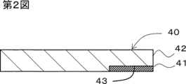
- FIG. 4 is a cross-sectional view of a mold used in the method of manufacturing a joined body according to the embodiment; 1. It is sectional drawing of the 1st base material which concerns on the 1st aspect manufactured using the metal mold
- FIG. 3 is a plan view of the first substrate of FIG. 2 viewed from the side where the solid bonding agent is present;
- FIG. 3 is a vertical cross-sectional view of a joined body including the first base material of FIG. 2;
- FIG. 5 is a vertical cross-sectional view along line XX of the joint shown in FIG. 4;
- FIG. 10 is a vertical cross-sectional view of a joined body according to another aspect;
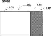
- FIG. 10 is a plan view of a first base material according to another aspect;
- FIG. 10 is a plan view of a first base material according to another aspect;
- FIG. 10 is a plan view of a first base material according to another aspect;
- FIG. 10 is a plan view of a first base material according
- FIG. 10 is a plan view of a first base material according to another aspect;
- FIG. 10 is a plan view of a first base material according to another aspect;
- FIG. 10 is a plan view of a first base material according to another aspect;
- FIG. 10 is a plan view of a first base material according to another aspect;
- FIG. 4 is a vertical cross-sectional view showing a state before bonding of a bonded body according to a certain aspect;
- FIG. 10 is a vertical cross-sectional view showing a state before bonding of a bonded body according to another embodiment;
- FIG. 10 is a vertical cross-sectional view showing a state before bonding of a bonded body according to another embodiment;
- FIG. 10 is a vertical cross-sectional view showing a joined body according to another aspect;
- FIG. 16 is a plan view of the joined body of FIG. 15 viewed from above (from the second base material side of the two base materials);
- FIG. 16 is a perspective view of a first base material constituting the joined body of FIG. 15;
- FIG. 10 is a vertical cross-sectional view showing a joined body according to another aspect;
- FIG. 19 is a plan view of the joined body of FIG. 18 as seen from below (from the second substrate side of the two substrates);
- joining means joining things together, and adhesion and welding are subordinate concepts.
- Adhesion means bonding two adherends (objects to be adhered) via an organic material (thermosetting resin, thermoplastic resin, etc.) such as tape or adhesive.
- Welding means that the surface of a thermoplastic resin or the like is melted by heat and is brought into a bonded state by utilizing entanglement and crystallization due to molecular diffusion that occur in the process of cooling.
- a to B indicating a numerical range indicates a numerical range including A and B as endpoints. That is, it means "A or more and B or less" (when A ⁇ B) or "A or less and B or more" (when A>B).
- a solid bonding agent containing a thermoplastic resin having an epoxy equivalent of 1,600 or more or containing no epoxy group is placed on the wall surface of the cavity of the mold.
- a bonded body of the first base material and the second base material is formed. and a joining step of obtaining.
- a first base material integrated with a solid bonding agent in advance is used to bond with a second base material, and a step of applying a hot melt adhesive to one base material;
- the bonding process time can be shortened (shortened bonding process time) compared to the conventional manufacturing method that requires a step of bonding the other base material to an adhesive.
- the solid bonding agent is integrated with the first base material, the solid bonding agent, the first base material, and the second base material are separated from each other.
- the solid bonding agent, the first base material, and the second base material can be precisely bonded in a desired positional relationship (improved handling).
- the melt of the thermoplastic resin composition is solidified in a state of contact with the solid bonding agent, so that the resin molded body formed by solidifying the thermoplastic resin composition and the solid bonding. agent is firmly integrated.
- the solid bonding agent that is firmly integrated with the resin molded body is bonded to the second base material in this way, the first base material and the second base material can be firmly bonded (bonding strength improvement).
- the manufacturing process of the resin molded body and the process of integrating the solid bonding agent into the resin molded body are performed simultaneously, compared with the conventional manufacturing method of performing these separately. , which simplifies the manufacturing process.
- the manufacturing process is faster than when the liquid adhesive is applied to the first base material and dried to manufacture the first base material with the bonding agent. can be simplified.
- the first base material integrated with the solid bonding agent can be manufactured at a factory or the like, it is necessary to fix the solid bonding agent to the first base material when assembling the first base material and the second base material. , thus simplifying the assembly work. (simplification of the manufacturing process (particularly assembly work)). Each step will be described below.
- thermoplastic resin composition is injected into a cavity in which a solid bonding agent is installed on the wall surface of the cavity of the mold, thereby forming a resin molded article made of the thermoplastic resin composition. and the solid bonding agent are integrated to obtain a first base material.
- Solid bonding agent Solid bonding agent
- the "solid" of the solid bonding agent means that it is solid at room temperature, that is, it has no fluidity at 23° C. under no pressure. It is preferable that the solid bonding agent has properties such that it can retain its shape without being deformed for 30 days or more under a non-pressurized state at 23° C. and does not deteriorate.
- the material of the solid bonding agent is not particularly limited, and contains, for example, a resin component.
- the content of the resin component in the solid bonding agent is preferably 50% by mass or more, more preferably 70% by mass or more, still more preferably 80% by mass or more, still more preferably 90% by mass or more, and even more preferably 99% by mass. % or more.
- the resin component in the solid bonding agent contains a thermoplastic resin having an epoxy equivalent of 1,600 or more or containing no epoxy group, and more preferably contains the thermoplastic resin as a main component.
- the "main component" means the component with the highest content among the resin components in the solid bonding agent.
- the content of the thermoplastic resin in the resin component of the solid bonding agent is preferably 50% by mass or more, more preferably 70% by mass or more, still more preferably 80% by mass or more, and even more preferably 90% by mass or more. More preferably, it is 99% by mass or more.
- the softening point of the solid bonding agent is preferably 20 to 200°C, more preferably 40 to 160°C, still more preferably 45 to 120°C, from the viewpoint of heat resistance and weldability.
- the open time can be lengthened.
- the open time means the time limit from when the bonding agent is applied or placed on the first base material to when the second base material is completely placed. Within the open time, the bonding strength of the bonding agent does not decrease, and the two substrates can be bonded with sufficient bonding strength. The longer the open time, the higher the convenience.
- thermoplastic resin examples include polyolefin and acid-modified products thereof, polystyrene, polymethyl methacrylate, AS resin, ABS resin, thermoplastic aromatic polyesters such as polyethylene terephthalate and polybutylene terephthalate, polycarbonate, polyimide, and polyamide. , polyamideimide, polyetherimide, polyethersulfone, polyphenylene ether and modified products thereof, polyphenylene sulfide, polyoxymethylene, polyarylate, polyetherketone, polyetheretherketone, polyetherketoneketone, thermoplastic epoxy, etc. One or more can be used.
- thermoplastic resin contains at least one selected from thermoplastic epoxy resins and phenoxy resins, from the viewpoint of obtaining a bonded body with excellent bondability in a short bonding process time and from the viewpoint of lengthening the open time. is preferred, and at least one selected from thermoplastic epoxy resins and phenoxy resins is preferred.
- the content of at least one selected from thermoplastic epoxy resins and phenoxy resins in the total amount of resins contained in the solid bonding agent is preferably 60 to 100% by mass, more preferably 80 to 100% by mass, and still more preferably 90 to 100% by weight, for example 100% by weight.
- the bonding process time means the time from the start point to the end point, with the start point being the point at which the bonding of both base materials is started and the point at which the production of the bonded body is completed.
- the start point of that process is the starting point.
- the "existing base material” means a base material that already has a shape as a base material before starting bonding with a bonding agent.
- the thermoplastic resin composition for injection molding does not yet have a shape as a base material at the start of injection molding, so the "existing base material "isn't it. Therefore, in the manufacturing method according to the present embodiment, the starting point means the time point at which bonding of the bonding agent to the existing second base material is started.
- the starting point is the time when the application is started.
- the point at which the solid bonding agent is applied to one of the substrates also represents the starting point.
- the joining of the solid joining agent and the first base material Steps can be omitted, thus shortening the bonding process time.
- the epoxy equivalent of the thermoplastic resin is 1,600 or more, preferably 2,000 or more, more preferably 5,000 or more, still more preferably 9,000 or more, and is at least the detection limit. Most preferably, substantially no epoxy groups are detected. As a result, the content of terminal epoxy groups is small or substantially absent, so that storage stability is excellent and long-term storage at room temperature is possible.
- the epoxy equivalent (the weight of the thermoplastic resin containing 1 mol of epoxy groups) referred to here is the value of the epoxy equivalent of the thermoplastic resin contained in the solid bonding agent before bonding, and is defined in JIS-K7236:2001. It is a value (unit: "g/eq.") measured by the method described above.
- the solvent-diluted product is the solid content excluding the solvent. It is a value calculated as a resin weight. In addition, in the case of a mixture of two or more resins, it can be calculated from each content and epoxy equivalent. The epoxy equivalent can be specifically measured and calculated by the method described in Examples.
- thermoplastic resin (especially thermoplastic epoxy resin and phenoxy resin) is more preferably an amorphous thermoplastic resin, and the amorphous thermoplastic resin has an epoxy equivalent of 1,600 or more or does not contain an epoxy group and
- the heat of fusion is preferably 15 J/g or less.
- a solid bonding agent mainly composed of an amorphous thermoplastic resin having an epoxy equivalent of 1,600 or more and a heat of fusion of 15 J/g or less
- the solid bonding agent does not flow out even in a molten state, and a high bonding strength can be stably obtained.
- the amorphous thermoplastic resin in this embodiment means a resin having a heat of fusion of 15 J/g or less.
- the heat of fusion is considered to be 15 J/g or less.
- the heat of fusion is calculated from the area of the endothermic peak in DSC (differential scanning calorimeter) and the weight of the thermoplastic resin component.
- DSC differential scanning calorimeter
- an inorganic filler or the like is contained in the solid bonding agent, it is calculated from the weight of the resin component excluding the inorganic filler.
- 2 to 10 mg of the sample is weighed, placed in an aluminum pan, and heated from 23 ° C. to 200 ° C. or higher at 10 ° C./min using a DSC (DSC8231 manufactured by Rigaku Co., Ltd.) to obtain a DSC curve.
- DSC DSC8231 manufactured by Rigaku Co., Ltd.
- the heat of fusion can be specifically measured and calculated by the method described in Examples.
- the heat of fusion of the thermoplastic resin is preferably 80 J/g or less, more preferably 60 J/g or less, still more preferably 15 J/g or less, still more preferably 11 J/g or less, and more preferably 11 J/g or less. It is more preferably 7 J/g or less, still more preferably 4 J/g or less, and most preferably the melting peak is below the detection limit.
- the melting point is preferably 50 to 400°C, more preferably 60 to 350°C, even more preferably 70 to 300°C. .
- the film Since the film has a melting point in the range of 50 to 400° C., the film is efficiently deformed and melted by heating, and effectively wets and spreads over the bonding surface, resulting in high bonding strength.
- the melting point of a thermoplastic resin means the temperature at which the thermoplastic resin melts and begins to have fluidity.
- the melting point can also be measured, for example, by the melting peak temperature measured by DSC. The melting point can be specifically measured and calculated by the method described in Examples.
- the content of the thermoplastic resin in the resin component of the solid bonding agent is preferably 50% by mass or more, more preferably 70% by mass or more, and more preferably 70% by mass or more, from the viewpoint of obtaining a bonded body excellent in bondability in a short bonding process time. It is preferably 80% by mass or more, more preferably 90% by mass or more, still more preferably 99% by mass or more, for example 100% by mass.
- thermosetting adhesives it is difficult to dismantle the joined body, it is difficult to separate and recycle the dissimilar materials that make up the joined body (that is, poor recyclability).
- rice field On the other hand, when the solid bonding agent contains a thermosetting resin, it can be softened and melted by heat, and the base materials can be easily separated from each other, so that the recyclability is excellent.
- the solid bonding agent is thermoplastic, it can reversibly repeat softening/melting and curing, and is excellent in repairability.
- the thermoplastic epoxy resin comprises (a) a bifunctional epoxy resin monomer or oligomer and (b) two functional groups that are the same or different selected from the group consisting of phenolic hydroxyl groups, carboxyl groups, mercapto groups, isocyanate groups and cyanate ester groups. It is preferably a polymer with a bifunctional compound having By using such a compound, the polymerization reaction forming a linear polymer proceeds preferentially, making it possible to obtain a thermoplastic epoxy resin having desired properties.
- the (a) bifunctional epoxy resin monomer or oligomer refers to an epoxy resin monomer or oligomer having two epoxy groups in the molecule.
- Specific examples of (a) include bisphenol A type epoxy resin, bisphenol F type epoxy resin, bifunctional phenol novolac type epoxy resin, bisphenol AD type epoxy resin, biphenyl type epoxy resin, bifunctional naphthalene type epoxy resin, Bifunctional alicyclic epoxy resins, bifunctional glycidyl ester type epoxy resins (e.g. diglycidyl phthalate, diglycidyl tetrahydrophthalate, dimer acid diglycidyl ester, etc.), bifunctional glycidyl amine type epoxy resins (e.g.
- bifunctional heterocyclic epoxy resins bifunctional diarylsulfone-type epoxy resins, hydroquinone-type epoxy resins (e.g., hydroquinone diglycidyl ether, 2,5-di-tert-butylhydroquinone diglycidyl ether, resorcinol) diglycidyl ether, etc.), bifunctional alkylene glycidyl ether compounds (eg, butanediol diglycidyl ether, butenediol diglycidyl ether, butynediol diglycidyl ether, etc.), bifunctional glycidyl group-containing hydantoin compounds (eg, 1,3- diglycidyl-5,5-dialkylhydantoin, 1-glycidyl-3-(glycidoxyalkyl)-5,5-dialkylhydantoin, etc.),
- Examples of the (b) bifunctional compound having a phenolic hydroxyl group include mononuclear aromatic dihydroxy compounds having one benzene ring such as catechol, resorcinol, hydroquinone, bis(4-hydroxyphenyl)propane (bisphenol A ), bis(4-hydroxyphenyl)methane (bisphenol F), bisphenols such as bis(4-hydroxyphenyl)ethane (bisphenol AD), compounds having condensed rings such as dihydroxynaphthalene, diallylsorcin, diallylbisphenol A, tri Bifunctional phenol compounds into which an allyl group is introduced, such as allyldihydroxybiphenyl, dibutylbisphenol A, and the like.
- mononuclear aromatic dihydroxy compounds having one benzene ring such as catechol, resorcinol, hydroquinone, bis(4-hydroxyphenyl)propane (bisphenol A ), bis(4-hydroxyphenyl)methane (bisphenol F
- carboxyl group-containing compound (b) examples include adipic acid, succinic acid, malonic acid, cyclohexanedicarboxylic acid, phthalic acid, isophthalic acid, and terephthalic acid.
- Examples of the (b) bifunctional compound having a mercapto group include ethylene glycol bisthioglycolate and ethylene glycol bisthiopropionate.
- Specific examples of the isocyanate group-containing bifunctional compound (b) include diphenylmethane diisocyanate (MDI), isophorone diisocyanate (IPDI), hexamethylene diisocyanate (HMDI), and tolylene diisocyanate (TDI). .
- cyanate ester group-containing bifunctional compound examples include 2,2-bis(4-cyanatophenyl)propane, 1,1-bis(4-cyanatophenyl)ethane, and bis (4-cyanatophenyl)methane and the like.
- a bifunctional compound having a phenolic hydroxyl group is preferable from the viewpoint of obtaining a thermoplastic polymer.
- a bifunctional compound having two phenolic hydroxyl groups and a bisphenol structure or a biphenyl structure is heat resistant and It is preferable from the viewpoint of bondability, and bisphenol A, bisphenol F or bisphenol S is preferable from the viewpoint of heat resistance and cost.
- the above (a) is a bisphenol A type epoxy resin, a bisphenol F type epoxy resin, a bisphenol S type epoxy resin, or a biphenyl type epoxy resin
- the above (b) is bisphenol A, bisphenol F or bisphenol S
- the above (a) The polymer obtained by the polymerization of ) and (b) has a structure in which a paraphenylene structure and an ether bond are the main skeleton, and the main chain is connected by an alkylene group, and the hydroxyl group generated by polyaddition is arranged in the side chain. have.
- the linear structure composed of the paraphenylene skeleton can enhance the mechanical strength of the polymer after polymerization, and the hydroxyl groups arranged in the side chains can improve the adhesion to the substrate. As a result, high bonding strength can be achieved while maintaining the workability of the thermosetting resin. Furthermore, in the case of a thermoplastic resin, it can be recycled and repaired by being softened and melted by heat, thereby improving the recyclability and repairability, which are problems in thermosetting resins.
- a phenoxy resin is a polyhydroxy polyether synthesized from bisphenols and epichlorohydrin, and has thermoplasticity.
- a method by direct reaction of dihydric phenols and epichlorohydrin, and a method by addition polymerization reaction of diglycidyl ether of dihydric phenols and dihydric phenols are known.
- the phenoxy resin may be obtained by any production method.
- dihydric phenols include, for example, phenols such as bisphenol A, bisphenol F, bisphenol S, biphenol, biphenylenediol, and fluorenediphenyl; ethylene glycol, propylene glycol, diethylene glycol. and other aliphatic glycols.
- bisphenol A, bisphenol F, and bisphenol S are preferable from the viewpoint of cost, bondability, viscosity, and heat resistance. These may be used individually by 1 type, or may use 2 or more types together.
- a phenoxy resin has a chemical structure similar to that of an epoxy resin, and has a structure in which a paraphenylene structure and an ether bond are used as a main skeleton, a main chain connecting them, and hydroxyl groups are arranged in side chains.
- the thermoplastic resin preferably has a weight average molecular weight (Mw) of 10,000 to 500,000, more preferably 18,000 to 300,000, and more preferably 20,000 to 200,000. is more preferred, and 30,000 to 60,000 is more preferred.
- Mw weight average molecular weight
- the weight-average molecular weight is within this range, the balance between thermoplasticity and heat resistance is good, and a joined body can be obtained by efficient melting, and its heat resistance is also high.
- the weight average molecular weight is 10,000 or more, the heat resistance is excellent, and when it is 500,000 or less, the viscosity at the time of melting is low and the bondability is high.
- the solid bonding agent may or may not contain fillers or additives as components other than the resin component within a range that does not hinder the object of the present invention.
- fillers examples include inorganic fillers and organic fillers (resin powder).
- inorganic fillers include spherical fused silica, metal powders such as iron, silica sand, talc, calcium carbonate, mica, acid clay, diatomaceous earth, kaolin, quartz, titanium oxide, silica, phenolic resin microballoons, glass balloons, and the like. is mentioned.
- the content of the filler in 100% by volume of the total amount of the solid bonding agent is preferably 50% by volume or less, more preferably 30% by volume or less, and more preferably 20% by volume. is more preferably 10% by volume or less, and most preferably 10% by volume or less.
- the volume of the filler can be obtained by dividing the weight of the filler contained in the solid bonding agent by the true specific gravity of the filler.
- the content of the resin component in 100% by volume of the total amount of the solid bonding agent is preferably 10% by volume or more, more preferably 20% by volume or more, still more preferably 30% by volume or more, and even more preferably 50% by volume or more. is 80% by volume or more, 90% by volume or more in another embodiment, and 99% by volume or more in another embodiment.
- additives include viscosity modifiers such as reactive diluents, antifoaming agents, coupling agents such as silane coupling agents, and pigments.
- the content of the additive in the solid bonding agent is preferably 10% by mass or less, more preferably 5% by mass or less, and even more preferably 1% by mass or less.
- the content of the resin component in the solid bonding agent is preferably 10% by mass or more, more preferably 20% by mass or more, still more preferably 30% by mass or more, still more preferably 50% by mass or more, and in one aspect, 80% by mass or more. , 90% by mass or more in another aspect, and 99% by mass or more in another aspect.
- the form of the solid binder is not particularly limited, it preferably has any form selected from the group consisting of film, rod, pellet and powder.
- the thickness of the solid bonding agent is not particularly limited, but from the viewpoint of obtaining a bonded body with excellent bondability in a short bonding process time, the thickness is preferably 1 mm or less, and 0.5 mm or less. is more preferably 0.3 mm or less, even more preferably 0.2 mm or less, and most preferably 0.1 mm or less. From the viewpoint of obtaining high bonding strength, the thickness is preferably 0.01 mm or more, more preferably 0.05 mm or more, and still more preferably 0.08 mm or more.
- the film may be a single layer or a laminate consisting of multiple layers. is preferred.
- the solid bonding agent may have tackiness as long as it does not impair the bonding strength and heat resistance.
- the tackiness can be used to temporarily fix the solid bonding agent to the wall surface in the cavity of the mold when manufacturing the first base material. If it has tackiness, it can temporarily fix the first base material and the second base material. Storage of the first base material is easy when there is no tackiness.
- the method for producing the solid bonding agent is not particularly limited, but a film-like solid bonding agent can be obtained by heating or heating and compressing the resin composition.
- a film-like solid bonding agent containing at least one selected from the thermoplastic epoxy resin and the phenoxy resin is combined with one or more of raw material monomers and raw material oligomers for the thermoplastic epoxy resin and the phenoxy resin.
- the catalyst can be produced by heating and polymerizing.
- a solvent may be added to reduce viscosity and facilitate stirring. If a solvent is added, it must be removed, and a solid bonding agent may be obtained by performing drying or polymerization or both on a release film or the like.
- tertiary amines such as triethylamine and 2,4,6-tris(dimethylaminomethyl)phenol
- phosphorous compounds such as triphenylphosphine, and the like are preferably used.
- triphenylphosphine is preferable from the viewpoint of stability.
- the solvent include cyclohexanone and methyl ethyl ketone, and cyclohexanone and methyl ethyl ketone are preferred.
- Examples of the method of heat-compressing the resin composition include a method of compressing with a heated press (heat press) or the like.
- the temperature of the hot press is preferably 120 to 250°C, more preferably 130 to 200°C, still more preferably 140 to 180°C.
- the compression time when compressing the resin composition with a hot press is preferably 0.5 to 4 hours, more preferably 0.5 to 3 hours, and still more preferably 0.5 to 2 hours. is.
- thermoplastic resin composition to be injected into the cavity contains a thermoplastic resin, preferably a thermoplastic resin as a main component.
- the "main component” means the component with the highest content among the resin components in the thermoplastic resin composition.
- the content of the thermoplastic resin in the resin component of the thermoplastic resin composition is preferably 50% by mass or more, more preferably 70% by mass or more, still more preferably 80% by mass or more, and even more preferably 90% by mass or more, Even more preferably, it is 99% by mass or more.
- thermoplastic resin composition to be injected into the cavity preferably has completed polymerization during molding, and the thermoplastic resin does not require a polymerization reaction in the mold from the viewpoint of shortening the molding cycle. is preferred. In other words, it is preferable that the polymer be solidified only by cooling in the mold, instead of causing a polymerization reaction by heating in the mold.
- thermoplastic resin composition to be injected into the cavity preferably has a low viscosity when melted from the viewpoint of moldability. It is preferably not a resin or a thermoplastic epoxy resin.
- thermoplastic resin examples include polyolefin and acid-modified products thereof, polystyrene, polymethyl methacrylate, AS resin, ABS resin, thermoplastic aromatic polyesters such as polyethylene terephthalate and polybutylene terephthalate, polycarbonate, polyimide, and polyamide. , polyamideimide, polyetherimide, polyethersulfone, polyphenylene ether and modified products thereof, polyphenylene sulfide, polyoxymethylene, polyarylate, polyetherketone, polyetheretherketone, polyetherketoneketone, thermoplastic epoxy, etc. One or more can be used.
- thermoplastic aromatic polyesters such as polyethylene terephthalate and polybutylene terephthalate, polycarbonates, polyimides, polyamides, polyamideimides, polyetherimides, polyethersulfones, polyphenylene ethers and their modifications are preferred from the viewpoint of heat resistance and moldability.
- material, polyphenylene sulfide, and polyoxymethylene are preferred, and polyethylene terephthalate, polybutylene terephthalate, polycarbonate, polyimide, and polyamide are more preferred from the viewpoint of adhesion to the body-solid bonding agent.
- the thermoplastic resin composition may contain other components in addition to the resin component.
- Other types of ingredients include other ingredients used in the solid binders described above.
- the total content of fillers and reinforcing fibers in the total amount of 100% by volume of the thermoplastic resin composition is preferably 50% by volume or less, more preferably 30% by volume or less, and 20% by volume or less. Most preferably there is.
- the volume of the filler can be obtained by dividing the weight of the filler contained in the thermoplastic resin composition by the true specific gravity of the filler.
- the total content of fillers and reinforcing fibers in the total amount of 100% by volume is preferably 30% by volume or less, and preferably 10% by volume or less. More preferably, it is 5% by volume or less.
- the content of the resin component in 100% by volume of the total amount of the thermoplastic resin composition is preferably 10% by volume or more, more preferably 20% by volume or more, still more preferably 30% by volume or more, and even more preferably 50% by volume or more, In one aspect, it is 80% by volume or more, in another aspect it is 90% by volume or more, and in another aspect it is 99% by volume or more.
- the content of the additive in the thermoplastic resin composition is preferably 10% by mass or less, more preferably 5% by mass or less, and even more preferably 1% by mass or less.
- the content of the resin component in the thermoplastic resin composition is preferably 10% by mass or more, more preferably 20% by mass or more, still more preferably 30% by mass or more, still more preferably 50% by mass or more, and in one aspect 80% by mass. % or more, in another embodiment 90% by mass or more, and in another embodiment 99% by mass or more.
- the mold is not particularly limited, and conventional molds can be used, for example, the mold 1 shown in FIG. 1 can be used.
- the mold 1 has a first mold 10 and a second mold 20 .
- a cavity 30 is formed between the first mold 10 and the second mold 20 by closing the first mold 10 and the second mold 20 .
- the cavity 30 is covered with a first cavity surface 11 on the first mold 10 side and a second cavity surface 21 on the second mold 20 side.
- a first mold 10 is provided with a gate 12 that penetrates the first mold 10 and reaches a cavity 30 .
- An injection machine 13 is provided at the end of the gate 12 opposite to the cavity 30 .
- the injection machine 13 includes a hopper (not shown) and a cylinder (not shown).
- the second mold 20 is provided with a suction hole 22 that penetrates the second mold 20 and reaches the cavity 30 .
- An unillustrated negative pressure generating source (negative pressure pump, etc.) is provided at the end of the suction hole 22 opposite to the cavity 30 .
- a solid bonding agent 41 is placed on the wall surface of the cavity 30 so as to cover the suction hole 22 , and the negative pressure generation source is operated to reduce the pressure in the suction hole 22 , whereby the solid bonding agent 41 is adsorbed to the wall surface of the cavity 30 be done. In this manner, the solid bonding agent 41 can be temporarily fixed to the wall surface of the cavity 30 simply and accurately.
- the suction holes 22 may be omitted. For example, if the solid bonding agent has tackiness, the tackiness can be used to temporarily fix the solid bonding agent to the wall surface of the cavity 30 .
- injection molding conditions Conditions for injection molding are not particularly limited, but injection molding may be performed under the following conditions, for example.
- a thermoplastic resin composition is melted and the melted thermoplastic resin composition is injection molded into the cavity.
- the temperature of the thermoplastic resin composition at the time of injecting the thermoplastic resin composition into the cavity is preferably lower than the decomposition temperature and in a temperature range with fluidity.
- thermoplastic resin composition is injected into the cavity to obtain a resin molded article made of the thermoplastic resin composition and the solid bonding agent. It is possible to obtain a first base material formed by integrating with. In the obtained first base material, the surface of the solid bonding agent that was in contact with the wall surface in the cavity becomes an exposed surface.
- the first base material is obtained by integrating a resin molded article made of the thermoplastic resin composition and a solid bonding agent.
- the melting point of the first base material is not particularly limited, but from the viewpoint of absorbing bonding strength and dimensional error, it is preferably 100 to 400 ° C., more preferably 150 to 350 ° C., and 180 to 300 ° C. °C is more preferred.
- the softening point of the first base material is not particularly limited, but from the viewpoint of absorbing bonding strength and dimensional error, it is preferably 50 to 300 ° C., more preferably 80 to 250 ° C., and 100 ° C. to It is more preferably 230°C.
- the softening point of the solid bonding agent is preferably lower than the melting point of the resin molding from the viewpoint of adhesion between the resin of the first base material melted during injection molding and the solid bonding agent.
- the melting point of the solid bonding agent is preferably equal to or lower than the melting point of the resin molding resistance, and more preferably lower than the melting point of the resin molding resistance.
- the value obtained by subtracting the softening point of the solid bonding agent from the melting point of the resin molding is preferably above 0° C. and 300° C. or less, more preferably 20 to 280° C., still more preferably 40 to 250° C., and even more preferably 60 to 60° C. 220°C, more preferably 80 to 170°C.
- the softening point can be specifically measured and calculated by the method described in Examples.
- the surface of the solid bonding agent is preferably flush with the surface of the resin molding. This can prevent the solid bonding agent from protruding from the surface of the resin molding and increasing the thickness of the first base material.
- the obtained first base material at least part of the surface of the solid bonding agent is a non-exposed surface covered with the resin molding, and the rest of the surface of the solid bonding agent is an exposed surface not covered with the resin molding. is.
- the obtained first substrate when the solid bonding agent is film-shaped, the first surface of the solid bonding agent having the film shape, the second surface facing the first surface, and the first surface and the Of the side surfaces connecting to the second surface, part or all of the first surface may be exposed, part or all of the second surface may be exposed, and part of the side surfaces may be exposed.
- the film-shaped solid bonding agent in the first substrate preferably comprises the following (a) and the following (b), or preferably comprises the following (a) and the following (c).
- (a) One of the first surface and the second surface of the solid bonding agent is a non-exposed surface covered with the resin molding, and the other is an exposed surface not covered with the resin molding.
- Part of the side surface of the solid bonding agent is a non-exposed surface covered with the resin molding, and the rest of the side surface is an exposed surface not covered with the resin molding.
- All of the side surfaces of the solid bonding agent are non-exposed surfaces covered with the resin molding.
- the above (a) preferably includes the following (a1).
- FIG. 1 is a longitudinal sectional view of the first base material 40 according to the first embodiment
- FIG. 3 is a plan view of the first base material 40 viewed from the side where the solid bonding agent 41 exists.
- the first base material 40 is formed by integrating a resin molding 42 and a solid bonding agent 41 .
- the first base material 40 is plate-shaped.
- the solid bonding agent 41 is sheet-like.
- One of the first surface and the second surface of the solid bonding agent 41 (upper surface in FIG. 2) is a non-exposed surface covered with the resin molding 42, and the other (lower surface in FIG. 2) is covered with the resin molding 42.
- the exposed surface is flush with the surface of the resin molded body 42 and is a part of the surface of the first base material (that is, one surface of the first base material, the lower surface in FIG. 2). (corresponding to (a1) above).
- Part of the side surface of the solid bonding agent 41 is a non-exposed surface covered with the resin molded body 42, and the remaining side surface (ie, the remaining one side surface). is an exposed side surface that is not covered with the resin molding (corresponding to (b) above).
- the exposed side of solid bonding agent 41 is flush with the side of the first substrate.
- the first base material is obtained by integrating a resin molded body made of the thermoplastic resin composition and a solid bonding agent.
- the first base material and the second base material are joined by melting and then solidifying the solid bonding agent in a state in which the solid bonding agent of the first base material is in contact with the second base material.
- the method for solidifying the solid bonding agent after melting is selected from the group consisting of contact heating, warm air heating, hot press, infrared heating, hot plate welding, ultrasonic welding, vibration welding, high frequency induction welding, and high frequency dielectric welding. at least one method that is Among them, hot press, ultrasonic welding, and high-frequency induction welding are preferred.
- the oscillation frequency is preferably 10-70 kHz, more preferably 15-40 kHz.
- the ultrasonic wave application time is preferably 0.1 to 3 seconds, more preferably 0.2 to 2 seconds, from the viewpoint of adhesion and appearance.
- the pressure is preferably 0.01 to 20 MPa, more preferably 0.1 to 10 MPa, and even more preferably 0.2 to 5 MPa. Within such a pressure range, the solid bonding agent is efficiently deformed and effectively wets and spreads over the bonding surface, resulting in high bonding strength.
- the transmission frequency is preferably 100-2,000 kHz, more preferably 500-1,500 kHz, even more preferably 700-1,000 kHz.
- the high frequency application time is preferably 0.1 to 30 seconds, more preferably 0.2 to 10 seconds, from the viewpoint of adhesiveness and appearance.
- the pressure is preferably 0.01 to 20 MPa, more preferably 0.1 to 10 MPa, and even more preferably 0.2 to 5 MPa. Within such a pressure range, the solid bonding agent is efficiently deformed and effectively wets and spreads over the bonding surface, resulting in high bonding strength.
- the solid bonding agent is integrated into the first base material, when the first base material and the second base material are bonded together, the solid bonding agent may come off from the first base material or may be removed from the first base material. There is no concern that the position of the solid bonding agent in the joint will shift. Therefore, the first base material can be precisely bonded to the bonding position of the second base material, and the bonding operation is easy.
- the solid bonding agent contains a thermoplastic resin
- the resulting joined body has excellent recyclability and repairability because the first base material and the second base material can be separated by heating. , can be easily disassembled into a first substrate and a second substrate.
- the material of the second base material is preferably at least one selected from metal; glass; ceramic; resin such as thermoplastic resin and fiber reinforced plastic (FRP);
- FRP thermoplastic resin and fiber reinforced plastic
- the second substrate is metal, at least one of aluminum, copper, and iron is preferred.
- thermoplastic resin examples include polyolefin and acid-modified products thereof, polystyrene, polymethyl methacrylate, AS resin, ABS resin, thermoplastic aromatic polyesters such as polyethylene terephthalate and polybutylene terephthalate, polycarbonate, polyimide, and polyamide. , polyamideimide, polyetherimide, polyethersulfone, polyphenylene ether and modified products thereof, polyphenylene sulfide, polyoxymethylene, polyarylate, polyetherketone, polyetheretherketone, polyetherketoneketone, thermoplastic epoxy, etc. One or more can be used.
- the second base material is a thermosetting resin, among these, thermoplastic epoxy resins and phenoxy resins are used from the viewpoint of obtaining a bonded body with excellent bondability in a short bonding process time and from the viewpoint of extending the open time. At least one selected from is preferable.
- the first base material and the second base material may be made of the same material or may be made of different materials. Applies.
- Both the first base material and the second base material are preferably subjected to surface pretreatment for the purpose of removing surface contaminants and/or for anchoring effect.
- pretreatment include degreasing treatment, UV ozone treatment, blasting treatment, polishing treatment, plasma treatment, corona discharge treatment, laser treatment, etching treatment, and flame treatment.
- the pretreatment is preferably a pretreatment for washing the surface of the substrate or a pretreatment for roughening the surface.
- the substrate is made of aluminum, glass, ceramic, copper, or iron, at least one selected from the group consisting of degreasing treatment, UV ozone treatment, blasting treatment, polishing treatment, plasma treatment, and etching treatment is preferred.
- the substrate when the substrate is made of FRP, polypropylene, polycarbonate, polymethyl methacrylate, polyetherimide, polyamide, or polybutylene terephthalate, the group consisting of degreasing treatment, UV ozone treatment, blasting treatment, polishing treatment, plasma treatment and corona discharge treatment At least one more selected is preferred. Only one type of pretreatment may be used, or two or more types may be applied. As specific methods for these pretreatments, known methods can be used. Usually, hydroxyl groups derived from resins and reinforcing materials exist on the surface of FRP, and it is thought that hydroxyl groups originally exist on the surface of glass and ceramics. can increase the hydroxyl group of
- the degreasing treatment is a method of removing dirt such as oil on the base material surface by dissolving it with an organic solvent such as acetone or toluene.
- the UV ozone treatment is a method of cleaning and modifying the surface using the energy of short-wave ultraviolet rays emitted from a low-pressure mercury lamp and the power of ozone (O3) generated thereby.
- O3 ozone
- glass it is one of the surface cleaning methods for removing organic impurities on the surface.
- Cleaning and surface modification equipment using low-pressure mercury lamps are generally called “UV ozone cleaners”, “UV cleaning equipment”, “ultraviolet surface modification equipment” and the like.
- blasting examples include wet blasting, shot blasting, sandblasting, and the like. Among them, wet blasting is preferable because a more dense surface can be obtained than dry blasting.
- polishing treatment examples include buffing using an abrasive cloth, roll polishing using sandpaper, electrolytic polishing, and the like.
- the plasma treatment is a process in which a plasma beam is created with a high-voltage power supply and a rod and hits the surface of the material to excite molecules into a functional state. be done.
- the corona discharge treatment includes a method for modifying the surface of a polymer film, in which electrons emitted from an electrode cut the polymer main chain or side chain of the polymer surface layer and generate radicals as starting points. It is a method of generating hydroxyl groups and polar groups on the surface.
- the laser treatment is a technique for improving surface characteristics by rapidly heating and cooling only the surface of the base material by laser irradiation, and is an effective method for roughening the surface.
- Known laser processing techniques can be used.
- etching treatment examples include chemical etching treatments such as an alkali method, a phosphoric acid-sulfuric acid method, a fluoride method, a chromic acid-sulfuric acid method, and an iron salt method, and electrochemical etching treatments such as an electrolytic etching method. is mentioned.
- the flame treatment is a method of burning a mixed gas of combustion gas and air to convert oxygen in the air into plasma, and applying oxygen plasma to the object to be treated to make the surface hydrophilic.
- Known frame processing techniques can be used.
- a joined body consists of a first base material and a second base material. Both are integrated by a solid bonding agent.
- the exposed surface of the solid bonding agent constituting the first base material and the surface of the resin molding are flush with each other.
- the second base material may be in contact with not only the solid bonding agent of the first base material, but also part or all of the surface of the resin molding of the first base material.
- the solid bonding agent spreads in the thickness direction when the first substrate and the second substrate are integrated. It is pressed and deformed, and the solid bonding agent is prevented from protruding in the direction orthogonal to the thickness direction.
- FIG. 4 is a vertical cross-sectional view of a joined body 60 including the first base material 40 according to the first aspect.
- FIG. 5 is a vertical cross-sectional view along line IX-IX of the joint 60 shown in FIG.
- the exposed surface of the first base material 40 where the solid bonding agent 41 is exposed is in contact with the second base material 50 .
- the solid bonding agent 41 firmly bonds the first base material 40 and the second base material 50 together.
- the second base material 50 not only contacts the solid bonding agent 41 of the first base material 40, but also part of the surface of the resin molding 42 of the first base material 40 ( bottom surface) are also in contact with each other.
- the solid bonding agent 41 is pressed in the thickness direction and deformed, and the solid bonding agent 41 is deformed in the direction perpendicular to the thickness direction (Fig. 4 and the left-right direction in FIG. 5).
- the entire exposed surface of the solid bonding agent 41 is in contact with the second base material.
- the solid bonding agent 41 is in contact with the end of one side of the second base material 50 (the left end in FIG. 4).
- the solid bonding agent 41 is not in contact with the end of one side of the second base material 50 (the left end in FIG. It may be in contact with a part (lower surface in FIG. 6).
- FIG. 7 to 11 are plan views of the first base materials 40A to 40E according to the second to sixth embodiments, respectively, viewed from the side where the solid bonding agents 41A to 41E are present.
- a first base material 40A in FIG. 7 is formed by integrating a resin molding 42A and a solid bonding agent 41A.
- 40 A of 1st base materials are tabular.
- the solid bonding agent 41A is sheet-like.
- One of the first surface and the second surface of the solid bonding agent 41A is a non-exposed surface covered with the resin molded body 42A, and the other is an exposed surface not covered with the resin molded body 42A. It is flush with the surface of the molded body 42A and constitutes part of the surface of the first substrate (that is, one surface of the first substrate) (corresponding to (a1) above).
- a part of the side surface of the solid bonding agent 41A that is, a pair of opposed side surfaces (left side surface and right side surface in FIG.
- a first base material 40B in FIG. 8 is formed by integrating a resin molding 42B and a solid bonding agent 41B.
- the first base material 40B is plate-shaped.
- the solid bonding agent 41B is sheet-like.
- One of the first surface and the second surface of the solid bonding agent 41B is a non-exposed surface covered with the resin molded body 42B, and the other is an exposed surface not covered with the resin molded body 42B. It is flush with the surface of the molded body 42B and constitutes a part of the surface of the first substrate (that is, one surface of the first substrate) (corresponding to (a1) above).
- a part of the side surface of the solid bonding agent 41B that is, one of the four side surfaces of the solid bonding agent 41B (the left side surface in FIG. 8) is a non-exposed side surface covered with the resin molding 42B, and the remaining side surface ( The right side, upper side, and lower side in FIG. 8) are exposed side surfaces that are not covered with the resin molding 42B (
- a first base material 40C in FIG. 9 is formed by integrating a resin molding 42C and a solid bonding agent 41C.
- 40 C of 1st base materials are tabular.
- the solid bonding agent 41C is sheet-like.
- One of the first surface and the second surface of the solid bonding agent 41C is a non-exposed surface covered with the resin molded body 42C, and the other is an exposed surface not covered with the resin molded body 42C. It is flush with the surface of the molded body 42C and constitutes part of the surface of the first substrate (that is, one surface of the first substrate) (corresponding to (a1) above).
- the entire side surface of the solid bonding agent 41C is a non-exposed side surface covered with the resin molding 42C (corresponding to (c) above).
- a first base material 40D in FIG. 10 is formed by integrating a resin molding 42D and a solid bonding agent 41D.
- the first base material 40D is plate-shaped.
- the solid bonding agent 41D is sheet-like. Specifically, the solid bonding agent 41D has a frame shape formed by connecting the leading end and the trailing end of an elongated sheet, and more specifically, has a rectangular frame shape.
- One of the first surface and the second surface of the solid bonding agent 41D is a non-exposed surface covered with the resin molded body 42D, and the other is an exposed surface not covered with the resin molded body 42D.
- a part of the side surface of the solid bonding agent 41D (that is, the inner peripheral surface of the inner peripheral surface and the outer peripheral surface of the solid bonding agent 41D) is a non-exposed side surface covered with the resin molding 42D, and the remaining side surface (the outer peripheral surface ) is an exposed side surface not covered with the resin molding 42D (corresponding to (b) above).
- the first base material 40E in FIG. 11 is provided with two solid bonding agents 41 similar to those in FIG.
- the solid bonding agents 41A to 41E of the first base materials 40A to E are exposed.
- the surface is in contact with the second base material 50 .
- the first base material 40A to E and the second base material 50 are firmly bonded by the solid bonding agents 41A to 41E.
- the surface of the first base material and the surface of the second base material are flat, but are not limited to flat surfaces. It may be a curved surface or a surface having at least one of recesses and protrusions. It is preferable that such a joined body also has the above-mentioned (a) and (b) or (a) and (c).
- one of the first surface and the second surface of the first substrate has a concave or convex fitting portion
- one of the first surface and the second surface of the second substrate has a fitting portion.
- FIG. 12 is a vertical cross-sectional view showing a state before joining of a joined body according to a certain aspect.
- the surface of the first base material 40F that is in contact with the second base material 50F is a flat surface, and a part of the flat surface is a projecting portion 44F.
- a solid bonding agent 41F is provided on the plane of the convex portion 44F and its peripheral edge. A portion of the exposed surface of the solid bonding agent 41F that is continuous with the surface of the resin molded body 42F of the first base material 40F is flush with the surface of the resin molded body 42F.
- the surface of the second base material 50F that is in contact with the first base material 40F is a flat surface, and a part of the flat surface is a concave portion 51F.
- the first base material 40F and the second base material 50F are joined and integrated in a state where the convex part 44F and the concave part 51F are fitted. As a result, the first base material 40F and the second base material 50F are firmly bonded and integrated by the solid bonding agent 41F.
- FIG. 13 is a vertical cross-sectional view showing a state before bonding of a bonded body according to another embodiment.
- the surface of the first base material 40G that is in contact with the second base material 50G is a flat surface, and a part of the flat surface is a concave portion 44G.
- a solid bonding agent 41G is provided on the plane of the recess 44G and its peripheral edge. A portion of the exposed surface of the solid bonding agent 41G that is continuous with the surface of the resin molded body 42G of the first base material 40G is flush with the surface of the resin molded body 42G.
- the recess 44G has a planar shape with a flat bottom surface.
- the surface of the second base material 50G that is in contact with the first base material 40G is a flat surface, and a part of the flat surface is a projecting portion 51G.
- the convex portion 51G has a shape that follows the concave portion 44G.
- the first base material 40G and the second base material 50G are joined and integrated in a state where the concave part 44G and the convex part 51G are fitted. As a result, the first base material 40G and the second base material 50G are firmly bonded and integrated by the solid bonding agent 41G.
- FIG. 14 is a vertical cross-sectional view showing a state before bonding of a bonded body according to another embodiment.
- the surface of the first base material 40H that is in contact with the second base material 50H is a flat surface, and a part of the flat surface is a projecting portion 44H.
- the convex portion 44H has a vertical cross-sectional shape that tapers from the proximal end to the distal end.
- a solid bonding agent 41H is provided on the plane of the projection 44H and its peripheral edge. A portion of the exposed surface of the solid bonding agent 41H that is continuous with the surface of the resin molded body 42H of the first base material 40H is flush with the surface of the resin molded body 42H.
- the surface of the second base material 50H that is in contact with the first base material 40H is a flat surface, and a part of the flat surface is a concave portion 51H.
- the concave portion 51H has a shape that follows the convex portion 44H.
- the first base material 40H and the second base material 50H are joined and integrated in a state where the convex part 44H and the concave part 51H are fitted. As a result, the first base material 40H and the second base material 50H are firmly bonded and integrated by the solid bonding agent 41H.
- FIG. 15 is a longitudinal sectional view showing a joined body 60I according to another aspect.
- FIG. 16 is a plan view of the joined body 60I viewed from above (the second substrate 50I side of the first substrate 40 and the second substrate 50I).
- FIG. 17 is a perspective view of the second base material 50A that constitutes the joined body 60I. 15 to 17, arrow X indicates the vertical direction, arrow Y indicates the horizontal direction, and arrow Z indicates the thickness direction.
- the joined body 60I is composed of the first base material 40 and the second base material 50I.
- the first substrate 40 is as described above.
- the second base material 50I is substantially plate-shaped, and has projections 51A on one surface as shown in FIG. The projection 51A extends in the width direction of the second base material 50I.
- the projection 51A extends from one end side to the other end side in the width direction of the second base material 50I, but may extend partially in the width direction.
- the protrusion 51A has a triangular vertical cross section of the second base member 50I. 51 A of said protrusions are arrange
- the width (horizontal length) of the second base material 50I is smaller than the width (horizontal length) of the first base material 40I.
- the width (horizontal length) of the solid bonding agent 41 is greater than the width (horizontal length) of the second base material 50I.
- the width (horizontal length) of the solid bonding agent 41J may be the same as or smaller than the width (horizontal length) of the second base material 50I.
- the surface of the second base material 50I is superimposed and integrated so that it contacts the solid bonding agent 41 of the first base material 40 and does not contact the surface of the resin molding 42 of the first base material 40. ing.
- the solid bonding agent 41 is sandwiched between the resin molding 42 and the second base material 50I.
- An example of the manufacturing method of the joined body 60I having such a shape is as follows.
- the first base material 40 and the second base material 50I are overlaid.
- the projection 51A is brought into contact with the solid bonding agent 41 to form a superimposed body.
- ultrasonic waves are applied to the second base material 50I, and the resin molding 42 and the second base material 50I are pressed so as to compress the solid bonding agent 41 in the thickness direction.
- the protrusions 51A since the protrusions 51A are provided, the ultrasonic waves efficiently act on the solid bonding agent 41, and the ultrasonic welding can be carried out satisfactorily.
- the protrusion 51A may be omitted.
- the solid bonding agent 41 Since the solid bonding agent 41 is pressed by the resin molded body 42 and the second base material 50I without the resin molded body 42 and the second base material 50I coming into contact with each other, the solid bonding agent 41 adheres to the resin molded body 42 and the second base material 50I. It is pressed against the second base material 50I and comes into close contact with both, thereby increasing the bonding strength.
- FIG. 18 is a longitudinal sectional view showing a joined body 60J according to another embodiment.
- FIG. 19 is a plan view of the joined body 60J viewed from below (the second base material 50I side of the first base material 40J and the second base material 50J).
- arrow X indicates the vertical direction
- arrow Y indicates the horizontal direction
- arrow Z indicates the thickness direction.
- the joined body 60J is composed of a first base material 40J and a second base material 50J.
- the first base material 40J is obtained by reducing the width (horizontal direction length) of the first base material 40B in FIG.
- the second base material 50J is plate-shaped.
- the width (horizontal length) of the second base material 50J is greater than the width (horizontal length) of the first base material 40J.
- the width (horizontal length) of the solid bonding agent 41J is greater than the width (horizontal length) of the second base material 50I. However, the width (horizontal length) of the solid bonding agent 41J may be the same as or smaller than the width (horizontal length) of the second base material 50I.
- the surface of the second base material 50J is superimposed and integrated so that it contacts the solid bonding agent 41J of the first base material 40J and does not contact the surface of the resin molding 42J of the first base material 40J. ing.
- the solid bonding agent 41J is sandwiched between the resin molding 42J and the second base material 50J.
- An example of the manufacturing method of the joined body 60J having such a shape is as follows.
- the first base material 40J and the second base material 50J are overlaid.
- ultrasonic waves are applied to the second base material 50J, and the resin molding 42J and the second base material 50J are pressed so as to compress the solid bonding agent 41J in the thickness direction. Since the solid bonding agent 41J is pressed by the resin molded body 42J and the second base material 50J without the resin molded body 42J and the second base material 50J coming into contact with each other, the solid bonding agent 41J is bonded to the resin molded body 42J and the second base material 50J. It is pressed against the second base material 50J and comes into close contact with both, thereby increasing the bonding strength.
- a part of the surface of the solid bonded body facing the second base material may be in contact with the second base material and bonded, and the second base material of the solid bonded body may be bonded. The entire surface facing the material may be in contact with and bonded to the second substrate. Moreover, the second base material may or may not be in contact with the resin molding that constitutes the first base material.
- reference numeral 43 denotes a concave portion for receiving the solid bonding agent 41 in the resin molded body 42 forming the first base material 40. As shown in FIG. Similarly, reference numerals 43A to 43H are also recesses for receiving the solid bonding agent in the resin molded body forming the first base material.
- First base material and second base material The following base materials were used as the first base material and the second base material.
- first base material is produced by integrating a resin molded body made of a thermoplastic resin composition and a solid bonding agent by injection molding, the following conditions are applied. A melted resin pellet was used for injection molding as a thermoplastic resin composition.
- the projection was formed by using a mold in which a concave portion having a shape similar to the projection was formed on the wall surface of the cavity.
- the base material used for high-frequency induction welding was not provided with the protrusions.
- ⁇ PBT (polybutylene terephthalate) ⁇ VAROX (TM) 420-1001 (melting point: 225°C) manufactured by SABIC was injection-molded (resin temperature: 260°C, mold temperature: 50°C), and a test piece measuring 45 mm (length) x 18 mm (width) x 1.5 mm (thickness) (softening point: 207° C.) was obtained. Used without surface treatment.
- ⁇ PC (Polycarbonate) ⁇ LEXAN (TM) 121R (melting point: 220°C) manufactured by SABIC was injection-molded (resin temperature: 290°C, mold temperature: 90°C), and a test piece of length 45 mm x width 10 mm x thickness 3 mm (softening point: 129°C) was obtained. Obtained. Used without surface treatment. "iron” The surface of SPCC-SD was blasted to obtain a test piece of length 45 mm x width 18 mm x thickness 1.5 mm. "aluminum” The surface of A6061-T6 was blasted to obtain a test piece of length 45 mm x width 18 mm x thickness 1.5 mm.
- thermoplastic epoxy resin and a phenoxy resin were dissolved in tetrahydrofuran and measured using Prominence 501 (manufactured by Showa Science Co., Ltd., Detector: Shodex (registered trademark) RI-501 (manufactured by Showa Denko Co., Ltd.)) under the following conditions.
- Prominence 501 manufactured by Showa Science Co., Ltd.
- Detector Shodex (registered trademark) RI-501 (manufactured by Showa Denko Co., Ltd.)
- Column LF-804 ⁇ 2 columns manufactured by Showa Denko Co., Ltd. Column temperature: 40 ° C.
- Eluent Tetrahydrofuran
- Calibration method Conversion by standard polystyrene
- the softening point was measured according to ISO-75-2/A. Since it is not practical to apply the softening point measurement method of ISO-75-2/A to a solid adhesive with a small thickness, the softening point of the solid adhesive is determined by taking the glass transition point in the DSC curve as the softening point. bottom.
- epoxy equivalent It was measured according to JIS K-7236:2001 and converted into a value as resin solid content. In the case of a simple mixture without reaction, it was calculated from each epoxy equivalent and content.
- the thickness of the solid bonding agent was measured using MDC-25MX manufactured by Mitutoyo Corporation after being left in an atmosphere of 23° C. and 50% humidity for 24 hours.
- the bonding process time was measured as follows. The time from the start point to the end point was measured, with the point of time when the bonding of both base materials was started as the start point and the point of time when the production of the bonded body was completed as the end point. Specifically, in all of the examples and Comparative Examples 1 to 3, the starting point was the point at which the first base material and the second base material were overlapped, and the end point was the point at which the production of the joined body was completed. . In Comparative Example 4, the starting point was the time when the application of the thermosetting liquid epoxy adhesive E-250 as a bonding agent to the first base material and the second base material was started, and the end point was the time when the bonding body was completed.
- a first base material, a second base material, and a liquid resin composition as a bonding agent were prepared, and the starting point was the time when bar coating of the bonding agent on the second substrate was started. , and the end point was defined as the time point when the production of the conjugate was completed.
- a first base material, a second base material, and a film as a bonding agent were prepared, and the starting point was the time when these were superimposed in the order of the first base material, the film, and the second base material, and bonding was performed. The end point was defined as the completion of body preparation.
- Handleability was measured as follows. When the first substrate and the solid bonding agent were fixed at the start of the bonding process, it was evaluated as good (A), and when the first substrate and the solid bonding agent were not fixed, it was evaluated as unsuitable (B).
- the tensile shear bonding strength test was performed at 23° C. using the open time evaluation bonded body. If the shear bonding strength is 80% or more compared with the test pieces prepared by the methods of the above examples and comparative examples, it is judged as good (A), and if it is less than 80%, it is judged as unsuitable (B).
- a good open time evaluation (A) means that the open time is long and convenience is excellent.
- Examples 1-1, 1-2, and 1-3> (Production of solid bonding agent A1) JER (registered trademark) 1007 (manufactured by Mitsubishi Chemical Corporation, bisphenol A type epoxy resin, weight average molecular weight of about 10,000)1. 0 equivalent (203 g), 1.0 equivalent of bisphenol S (12.5 g), 2.4 g of triphenylphosphine, and 1,000 g of methyl ethyl ketone were charged, and the temperature was raised to 100°C under a nitrogen atmosphere with stirring. Dissolution was visually confirmed, and the mixture was cooled to 40° C. to obtain a resin composition P-1 having a solid content of about 20% by mass. The solvent was removed from this to obtain a thermoplastic epoxy resin as a solid component.
- a non-adhesive fluororesin film (Nitoflon (registered trademark) No. 900UL, manufactured by Nitto Denko Co., Ltd.) was placed on the upper and lower plates of the press, and the thermoplastic epoxy resin was applied onto the non-adhesive fluororesin film of the lower plate. After placement, the press was heated to 160° C., and the thermoplastic epoxy resin was thermally compressed for 2 hours to prepare a solid bonding agent A1 having a solid content of 100% by mass.
- the dimensions of the solid bonding agent A1 were the following two types.
- Table 1 shows the measurement results of the physical properties of the obtained solid bonding agent A1.
- the resin compositions obtained by other production examples described later were also subjected to similar measurements, and the results are also shown in Table 1 or Table 2.
- the PBT (Production of conjugate A1-1 (PBT/PA)
- the PBT (length 45 mm ⁇ width 18 mm ⁇ thickness 1.5 mm) was used.
- the aforementioned PA6 (length 45 mm, width 10 mm, thickness 3 mm, with protrusions) was used as the second base material 50I.
- the first base material 40 and the second base material 50I are placed so that the solid bonding agent A1 is in contact with the surface of the second base material 50I. They were overlapped so that the overlapping area was 5 mm long ⁇ 10 mm wide.
- the linear projections provided on the surface of the second base material 50I were overlapped so as to be in contact with the solid bonding agent A1.
- ultrasonic waves are applied using an ultrasonic welding machine (oscillator JII930S, press JIIP30S, manufactured by Seidensha Denshi Kogyo Co., Ltd.) to heat and pressurize the first base material 40 and the second base material 50I. joined.
- a pressure of 110 N pressure of 2.2 MPa
- an oscillation frequency of 28.5 kHz were used during pressurization.
- the ultrasonic wave application time was 1 second.
- the subsequent holding time was 1 second.
- a conjugate A1-1 was produced.
- a joined body for open time evaluation was produced in the same manner as above, except that the first base material 40 and the second base material 50I were allowed to stand still for 3 days and then superimposed and bonded together.
- joined bodies for open time evaluation were produced in the same manner.
- the aforementioned PC (length 45 mm, width 10 mm, thickness 3 mm) was used as the first base material 40J.
- the second base material 50J the aforementioned SPCC base material (length 45 mm, width 18 mm, thickness 1.5 mm) was used.
- the first base material 40J and the second base material 50J are overlapped so that the solid bonding agent A1 is in contact with the surface of the second base material 50J so as to have the same positional relationship as in FIGS. They were overlapped so that the overlapping area was 5 mm long ⁇ 10 mm wide.
- a high-frequency induction welding machine manufactured by Seidensha Denshi Kogyo Co., Ltd., oscillator UH-2.5K, press JIIP30S
- the applied pressure was 110 N (pressure 2.2 MPa)
- the oscillation frequency was 900 kHz.
- the oscillation time was set to 1 second.
- Joined body A1- was prepared in the same manner as joined body A1-2 except that the first base material 40J and the second base material 50J were used and the oscillation time of the high-frequency induction welding machine was set to 6 seconds. got 3.
- Example 2 (Production of solid bonding agent A2)
- Enotote (registered trademark) YP-50S manufactured by Nippon Steel Chemical & Materials Co., Ltd., phenoxy resin, weight average molecular weight of about 50,000) was added to a reactor equipped with a stirrer, reflux condenser, gas inlet tube, and thermometer. 20 g of cyclohexanone and 80 g of cyclohexanone were charged, heated to 60° C. with stirring, dissolved visually, and cooled to 40° C. to obtain a resin composition P-2 having a solid content of 20% by mass. The solvent was removed from this to obtain a thermoplastic epoxy resin as a solid component.
- a non-adhesive fluororesin film (Nitoflon (registered trademark) No. 900UL, manufactured by Nitto Denko Co., Ltd.) was placed on the upper and lower plates of the press, and the thermoplastic epoxy resin was applied onto the non-adhesive fluororesin film of the lower plate. After placement, the press was heated to 160° C., and the thermoplastic epoxy resin was heat-compressed for 2 hours to obtain a film-like solid bonding agent A2 having a solid content of 100% by mass. The weight average molecular weight was 50,000 and the epoxy equivalent was above the detection limit. No heat of fusion peak was detected in DSC.
- the dimensions of the solid bonding agent A2 were the following two types. ⁇ Length 10mm x Width 15mm x Thickness 100 ⁇ m ⁇ 7mm long x 10mm wide x 100 ⁇ m thick
- a bonded body was produced in the same manner as in Example 1 except that solid bonding agent A2 was used instead of solid bonding agent A1.
- Example 3> (Production of solid bonding agent A3) Solid bonding agent A2 and crystalline epoxy resin YSLV-80XY (manufactured by Nippon Steel Chemical & Materials Co., Ltd.) were mixed at a mass ratio of 98:2, pressed, and cut to obtain solid bonding agent A3. The weight average molecular weight was 36,000, the epoxy equivalent was 9600 g/eq, and the heat of fusion was 2 J/g.
- the dimensions of the solid bonding agent A3 were the following two types. ⁇ Length 10mm x Width 15mm x Thickness 100 ⁇ m ⁇ 7mm long x 10mm wide x 100 ⁇ m thick
- a bonded body was produced in the same manner as in Example 1 except that solid bonding agent A3 was used instead of solid bonding agent A1.
- Solid bonding agent A4 was obtained in the same manner as solid bonding agent A3 except that solid bonding agent A2 and crystalline epoxy resin YSLV-80XY (manufactured by Nippon Steel Chemical & Materials Co., Ltd.) were mixed at a mass ratio of 94:6. .
- the weight average molecular weight was 35,000
- the epoxy equivalent was 2100 g/eq
- the heat of fusion was 4 J/g.
- the dimensions of the solid bonding agent A4 were the following two types. ⁇ Length 10mm x Width 15mm x Thickness 100 ⁇ m ⁇ 7mm long x 10mm wide x 100 ⁇ m thick
- a bonded body was produced in the same manner as in Example 1, except that solid bonding agent A4 was used instead of solid bonding agent A1.
- Solid bonding agent A5 was obtained in the same manner as solid bonding agent A3 except that solid bonding agent A2 and crystalline epoxy resin YSLV-80XY (manufactured by Nippon Steel Chemical & Materials Co., Ltd.) were mixed at a mass ratio of 89:11. .
- the weight average molecular weight was 33,000, the epoxy equivalent was 1745 g/eq, and the heat of fusion was 11 J/g.
- the dimensions of the solid bonding agent A5 were the following two types. ⁇ Length 10mm x Width 15mm x Thickness 100 ⁇ m ⁇ 7mm long x 10mm wide x 100 ⁇ m thick
- a bonded body was produced in the same manner as in Example 1 except that solid bonding agent A5 was used instead of solid bonding agent A1.
- Example 6> (Production of solid bonding agent A6)
- a reactor equipped with a stirrer, a reflux condenser, a gas inlet pipe, and a thermometer is equipped with jER (registered trademark) 1007 (manufactured by Mitsubishi Chemical Corporation, bisphenol A type epoxy resin, molecular weight of about 4060) 1.0, etc. (203 g), 0.6 equivalents (12.5 g) of bisphenol S (molecular weight 250), 2.4 g of triphenylphosphine, and 1,000 g of methyl ethyl ketone were charged, and the temperature was raised to 100°C while stirring under a nitrogen atmosphere. . Dissolution was visually confirmed, and the mixture was cooled to 40° C.
- jER registered trademark
- thermoplastic epoxy resin As a solid component.
- a non-adhesive fluororesin film (Nitoflon (registered trademark) No. 900UL, manufactured by Nitto Denko Co., Ltd.) was placed on the upper and lower plates of the press, and the thermoplastic epoxy resin was applied onto the non-adhesive fluororesin film of the lower plate. After placement, the press was heated to 160° C., and the thermoplastic epoxy resin was heat-compressed for 2 hours to obtain a film-like solid bonding agent A6 having a solid content of 100% by mass and a thickness of 100 ⁇ m.
- the weight average molecular weight was about 30,000, and the epoxy equivalent was above the detection limit. No heat of fusion peak was detected in DSC.
- the dimensions of the solid bonding agent A6 were the following two types. ⁇ Length 10mm x Width 15mm x Thickness 100 ⁇ m ⁇ 7mm long x 10mm wide x 100 ⁇ m thick
- a bonded body was produced in the same manner as in Example 1 except that solid bonding agent A6 was used instead of solid bonding agent A1.
- Example 7 (Production of solid bonding agent A7) An amorphous polycarbonate film (Iupilon (registered trademark) FE2000, manufactured by Mitsubishi Engineering-Plastics Corporation, thickness 100 ⁇ m) was used as the solid assembly A7. No heat of fusion peak was detected in DSC.
- the dimensions of the solid bonding agent A7 were the following two types. ⁇ Length 10mm x Width 15mm x Thickness 100 ⁇ m ⁇ 7mm long x 10mm wide x 100 ⁇ m thick
- a bonded body was produced in the same manner as in Example 1 except that solid bonding agent A7 was used instead of solid bonding agent A1.
- Example 8> (Production of solid bonding agent A8) A crystalline polyamide-based hot-melt adhesive film NT-120 (manufactured by Nihon Matai Co., Ltd., thickness 100 ⁇ m) was used as a solid bonding body A8 as a solid bonding agent. The heat of fusion was 60 J/g. The dimensions of the solid bonding agent A8 were the following two types. ⁇ Length 10mm x Width 15mm x Thickness 100 ⁇ m ⁇ 7mm long x 10mm wide x 100 ⁇ m thick
- a bonded body was produced in the same manner as in Example 1 except that solid bonding agent A8 was used instead of solid bonding agent A1.
- thermosetting liquid epoxy adhesive E-250 manufactured by Konishi Co., Ltd., two liquid type of bisphenol type epoxy resin and amine curing agent
- E-250 thermosetting liquid epoxy adhesive
- the dimensions of the solid bonding agent B2 were the following two types. ⁇ Length 10mm x Width 15mm x Thickness 100 ⁇ m ⁇ 7mm long x 10mm wide x 100 ⁇ m thick
- a bonded body was produced in the same manner as in Example 1 except that solid bonding agent B2 was used instead of solid bonding agent A1.
- a bonded body was produced in the same manner as in Example 1, except that solid bonding agent B3 was used instead of solid bonding agent A1.
- Thermosetting liquid epoxy adhesive E-250 (manufactured by Konishi Co., Ltd., two-liquid type of bisphenol epoxy resin and amine curing agent) was used as the bonding agent, and PA6 was used as the second base material.
- the two liquids of the bonding agent are mixed, the mixture of the two liquids is applied to each of the surfaces of the first base material and the second base material over an area of 7 mm in length ⁇ 10 mm in width, and the overlapping area is formed within 1 minute. It was pasted together so that it might become 5 mm in length x 10 mm in width.
- the bonding agent was cured to a thickness of 0.1 mm by allowing it to stand in an oven at 100° C. for 1 hour while being fixed with a clip. After that, it was cooled to room temperature. Thus, a conjugate was produced. Also, a joined body for open time evaluation was produced in the same manner as above, except that the first base material and the second base material were allowed to stand still for 3 days and then superimposed and bonded together.
- PC/SPCC Manufacturing of joined body
- a joined body was fabricated in the same manner as the joined body (PBT/PA) except that the PBT (without solid bonding agent) was used as the first base material 40B and the aluminum base material was used as the second base material. Created.
- a joined body was produced in the same manner as in Example 1, except that the coating layer on the first substrate and the second substrate were superimposed. Also, a joined body for open time evaluation was produced in the same manner as above, except that the first base material and the second base material were allowed to stand still for 3 days and then superimposed and bonded together.
- a phenoxy resin coating layer of 7 mm long ⁇ 10 mm wide ⁇ 100 ⁇ m thick is formed on the first substrate by applying the liquid resin composition on the first substrate with a bar coater and allowing it to stand in an oven at 70° C. for 30 minutes. formed on the surface of The coating layer was used as bonding agent B6.
- a joined body was produced in the same manner as in Example 1, except that the coating layer on the first substrate and the second substrate were superimposed. Also, a joined body for open time evaluation was produced in the same manner as above, except that the first base material and the second base material were allowed to stand still for 3 days and then superimposed and bonded together.
- the bonded bodies according to Examples were excellent in 23° C. shear bonding strength, 80° C. shear bonding strength, and convenience (bonding process time, recyclability, repairability, and open time). Since the bonded body according to Comparative Example 1 does not have a solid bonding agent, it cannot bond the first base material and the second base material, and is inferior in recyclability, repairability, and open time. rice field. Since the bonded body according to Comparative Example 2 used a thermosetting resin as the solid bonding agent, the first base material in which the solid bonding agent and the base material were integrated could not be obtained. Since the joined body according to Comparative Example 3 had a low epoxy equivalent, the first base material and the second base material did not bond.
- the bonding strength between the first base material and the second base material was weak, and the repairability and open time properties were poor.
- the bonding agent was applied to the base material, the handling property was poor and the bonding process time was long.
- the time required for the bonding process was long because of the work required to In the joined body according to Comparative Example 7, since the solid bonding agent was not integrated with the first base material, the base material was coated with the solid bonding agent to form a coat layer. The process time was long.
- Joined bodies obtained by the manufacturing method of the present invention include, for example, door side panels, bonnet roofs, tailgates, steering hangers, A pillars, B pillars, C pillars, D pillars, crash boxes, power control unit (PCU) housings. , electric compressor parts (inner wall, intake port, exhaust control valve (ECV) insertion part, mount boss, etc.), lithium ion battery (LIB) spacer, battery case, automotive parts such as LED headlamps, smartphones, It is used as a notebook computer, a tablet computer, a smart watch, a large liquid crystal television (LCD-TV), an outdoor LED lighting structure, etc., but is not particularly limited to these examples.
- PCU power control unit
- electric compressor parts inner wall, intake port, exhaust control valve (ECV) insertion part, mount boss, etc.
- LIB lithium ion battery spacer
- automotive parts such as LED headlamps, smartphones, It is used as a notebook computer, a tablet computer, a smart watch, a large liquid
- first mold 20 second mold 30 cavity 11 first cavity surface 21 second cavity surface 12 gate 13 injection machine 22 suction hole 40, 40A to 40J first substrate 41, 41A to 41J solid Bonding agent 42, 42A to 42J Resin molded body 50, 50A to 50J Second substrate 60, 60A to 60J Bonded body
Landscapes
- Engineering & Computer Science (AREA)
- Mechanical Engineering (AREA)
- Manufacturing & Machinery (AREA)
- Laminated Bodies (AREA)
- Injection Moulding Of Plastics Or The Like (AREA)
- Lining Or Joining Of Plastics Or The Like (AREA)
Abstract
Description
液状型接着剤を用いた接合は、液状の樹脂組成物を塗布する塗布工程と、塗布後に前記樹脂組成物を重合反応させて硬化させる硬化工程が必要となる。
このため、液状型接着剤を用いて接合を行う場合、塗布工程においては樹脂組成物の塗布に時間がかかり、硬化工程においては重合反応に時間がかかり(すなわち、接合プロセス時間が長く)、利便性に欠けるという問題がある。
[1]エポキシ当量が1,600以上もしくはエポキシ基を含まない熱可塑性樹脂を含有する固形接合剤が金型の空洞内の壁面に設置されている状態において、前記空洞内に熱可塑性樹脂組成物を射出することにより、前記熱可塑性樹脂組成物からなる樹脂成形体と前記固形接合剤とが一体化してなる第一基材を得る、射出成形工程と、
前記第一基材の前記固形接合剤を第二基材に接面させた状態で前記固形接合剤を溶融後固化させることにより、前記第一基材と前記第二基材との接合体を得る接合工程と、
を有する、接合体の製造方法。
[2]前記固形接合剤に含まれる前記熱可塑性樹脂は、熱可塑性エポキシ樹脂及びフェノキシ樹脂から選ばれる少なくとも一種を含有する、上記[1]に記載の接合体の製造方法。
[3]前記固形接合剤に含まれる前記熱可塑性樹脂は、非晶性熱可塑性樹脂であり、
前記非晶性熱可塑性樹脂は、融解熱が15J/g以下である、上記[1]又は[2]に記載の接合体の製造方法。
[4]前記接合工程において、前記固形接合剤を、接触加熱、温風加熱、熱プレス、赤外線加熱、熱板溶着、超音波溶着、振動溶着、高周波誘導溶着、及び高周波誘電溶着からなる群より選ばれる少なくとも1種により溶融後固化させる、上記[1]~[3]のいずれかに記載の接合体の製造方法。
[5]前記固形接合剤の軟化点は、樹脂成形体の融点よりも低い、上記[1]~[4]のいずれかに記載の接合体の製造方法。
[7]前記接合工程において、前記第一基材と前記第二基材とを圧力0.01~20МPaの条件で行う、上記[1]~[6]のいずれかに記載の接合体の製造方法。
[8]前記第一基材において、前記固形接合剤の表面が前記樹脂成形体の表面と面一である、上記[1]~[7]のいずれかに記載の接合体の製造方法。
[9]前記空洞内の壁面に設置されている固形接合剤はフィルムである、上記[1]~[8]のいずれかに記載の接合体の製造方法。
[10]金型の空洞内の壁面に固形接合剤が設置されている状態において、前記空洞内に熱可塑性樹脂組成物を射出することにより、前記熱可塑性樹脂組成物からなる樹脂成形体と前記固形接合剤とが一体化してなる基材を得る、基材の製造方法であって、
前記固形接合剤は、熱可塑性エポキシ樹脂及びフェノキシ樹脂から選ばれる少なくとも一種であり、エポキシ当量が1,600以上もしくはエポキシ基を含まない非晶性熱可塑性樹脂を含有する、基材の製造方法。
本明細書において、接合とは、物と物とを繋合わせることを意味し、接着及び溶着はその下位概念である。接着とは、テープや接着剤の様な有機材(熱硬化性樹脂や熱可塑性樹脂等)を介して、2つの被着材(接着しようとするもの)を接合状態とすることを意味する。溶着とは、熱可塑性樹脂等の表面を熱によって溶融し、冷却を行う過程で生じる、分子拡散による絡み合いと結晶化を利用して接合状態とすることを意味する。
本明細書において、数値範囲を示す「A~B」の記載は、端点であるA及びBを含む数値範囲を示す。すなわち、「A以上B以下」(A<Bである場合)、又は「A以下B以上」(A>Bである場合)を意味する。
本実施形態に係る接合体の製造方法は、エポキシ当量が1,600以上もしくはエポキシ基を含まない熱可塑性樹脂を含有する固形接合剤が金型の空洞内の壁面に設置されている状態において、前記空洞内に熱可塑性樹脂組成物を射出することにより、前記熱可塑性樹脂組成物からなる樹脂成形体と前記固形接合剤とが一体化してなる第一基材を得る、射出成形工程と、
前記第一基材の前記固形接合剤を第二基材に接面させた状態で前記固形接合剤を溶融後固化させることにより、前記第一基材と前記第二基材との接合体を得る接合工程と、を有する。
また、当該製造方法によると、固形接合剤が第一基材中に一体化していることから、固形接合剤、第一基材及び第二基材の3点が別体となっている場合と比べて接合作業が容易であり、また固形接合剤と第一基材と第二基材とを所望の位置関係に精度よく接合することができる(ハンドリング性の向上)。
また、当該製造方法によると、射出成形工程において、熱可塑性樹脂組成物の溶融物を固形接合剤と接触した状態で固化させるため、熱可塑性樹脂組成物が固化してなる樹脂成形体と固形接合剤とが強固に一体化される。また、このように樹脂成形体と強固に一体化された固形接合剤と第二基材とを接合するため、第一基材と第二基材とも強固に接合させることができる(接合強度の向上)。
また、当該製造方法によると、樹脂成形体の製造プロセスと、当該樹脂成形体への固形接合剤の一体化プロセスとを、同時に実施するため、これらを別々に実施する従来の製造方法と比べて、製造プロセスを簡略化できる。また、予め固形接合剤が一体化された第一基材を用いるため、液状接着剤を第一基材に塗布し乾燥させて接合剤付き第一基材を製造する場合と比べて、製造プロセスを簡略化できる。更に、固形接合剤が一体化された第一基材は工場等で製造できるため、第一基材と第二基材の組み立て作業の際に、固形接合剤を第一基材に固定する必要が無く、従って組み立て作業を簡略化できる。(製造プロセス(特に組み立て作業)の簡略化)。
以下、各工程について説明する。
射出成形工程は、金型の空洞内の壁面に固形接合剤が設置されている状態において、前記空洞内に熱可塑性樹脂組成物を射出することにより、前記熱可塑性樹脂組成物からなる樹脂成形体と前記固形接合剤とが一体化してなる第一基材を得る工程である。
固形接合剤の「固形」とは、常温で固体、即ち23℃の加圧のない状態下において流動性が無いことを意味する。
前記固形接合剤は、23℃の加圧のない状態下において30日以上変形せずに外形を保持でき、さらに変質しない特性を備えることが望ましい。
固形接合剤中における当該樹脂成分は、エポキシ当量が1,600以上もしくはエポキシ基を含まない熱可塑性樹脂を含有するものであり、当該熱可塑性樹脂を主成分として含有するのがより好ましい。
ここで、「主成分」とは、固形接合剤中の樹脂成分のうちで最も含有量の高い成分を意味する。固形接合剤中の樹脂成分中における熱可塑性樹脂の含有量は、好ましくは50質量%以上、より好ましくは70質量%以上、更に好ましくは80質量%以上、より更に好ましくは90質量%以上、より更に好ましくは99質量%以上である。
固形接合剤中における樹脂成分がエポキシ当量が1,600以上もしくはエポキシ基を含まない熱可塑性樹脂を含有すると、オープンタイムを長くすることができる。
本明細書においてオープンタイムとは、第一基材の上に接合剤を塗布もしくは載せた後、第二基材を載せ終えるまでの制限時間を意味する。オープンタイム内であれば、接合剤の接合力が低下せず、十分な接合力で2つの基材を接合させることができる。オープンタイムが長いほど利便性が高い。
これらの中で、短い接合プロセス時間で接合性に優れた接合体を得る観点、及び、オープンタイムを長くする観点から、熱可塑性樹脂は、熱可塑性エポキシ樹脂及びフェノキシ樹脂から選ばれる少なくとも一種を含むことが好ましく、熱可塑性エポキシ樹脂及びフェノキシ樹脂から選ばれる少なくとも一種が好ましい。
固形接合剤中に含まれる樹脂の総量中における、熱可塑性エポキシ樹脂及びフェノキシ樹脂から選ばれる少なくとも一種の含有量は、好ましくは60~100質量%、より好ましくは80~100質量%、さらに好ましくは90~100質量%、例えば100質量%である。
ここで、「既存の基材」とは、接合剤との接合を開始する時点よりも以前において既に基材としての形状を有する基材を意味する。したがって、本実施の形態に係る製造方法にあっては、射出成形開始時点においては、射出成形用の熱可塑性樹脂組成物は未だ基材としての形状を有していないため、「既存の基材」ではない。したがって、本実施の形態に係る製造方法において、始点とは、既存の第二基材に対して接合剤の接合を開始した時点を意味する。これに対して、一方の基材に対して液状接着剤の塗布を開始する場合は、「両基材の接合を開始する前に接合剤を、既存の基材(第一基材又は第二基材)に積層する工程が別途必要である場合」といえるため、当該塗布を開始する時点を始点とする。同様に、一方の基材に対して固形接合剤を載せた時点も、始点を意味する。
本実施の形態に係る接合体の製造方法によると、すでに固形接合剤が一体化された第一基材を用いて第二基材と接合させるため、固形接合剤と第一基材との接合工程を省略することができ、したがって接合プロセス時間を短縮することができる。
ここで言うエポキシ当量(エポキシ基1モルが含まれる前記熱可塑性樹脂の重量)は、接合前の固形接合剤に含まれる熱可塑性樹脂のエポキシ当量の値であり、JIS-K7236:2001に規定された方法で測定された値(単位「g/eq.」)である。具体的には、電位差滴定装置を用い、臭素化テトラエチルアンモニウム酢酸溶液を加え、0.1mol/L過塩素酸-酢酸溶液を用い、溶媒希釈品(樹脂ワニス)は、溶媒を除いた固形分を樹脂重量として算出した値である。なお、2種以上の樹脂の混合物の場合はそれぞれの含有量とエポキシ当量から算出することもできる。
エポキシ当量は、具体的には実施例に記載の方法により測定及び算出することができる。
ここで、融解熱の測定に際して、融解熱のピークがブロードで、ノイズと分化できないもしくは、検出できない場合も、融解熱が15J/g以下とみなす。
融解熱は、具体的には実施例に記載の方法により測定及び算出することができる。
フィルムの主成分である熱可塑性樹脂が融点を有する場合、融点は50~400℃であることが好ましく、60℃~350℃であることがより好ましく、70℃~300℃であることが更に好ましい。50~400℃の範囲に融点があることにより、前記フィルムが加熱により効率よく変形及び溶融し、接合面に有効に濡れ広がるため高い接合力が得られる。
本明細書において、熱可塑性樹脂の融点とは、熱可塑性樹脂が溶融し、流動性を持ち始める温度を意味する。融点は例えば、DSCで測定される融解ピーク温度でも測定することができる。
融点は、具体的には実施例に記載の方法により測定及び算出することができる。
熱可塑性エポキシ樹脂は、(a)2官能エポキシ樹脂モノマーもしくはオリゴマーと(b)フェノール性水酸基、カルボキシル基、メルカプト基、イソシアネート基及びシアネートエステル基からなる群より選ばれる同一の又は異なる2つの官能基を有する2官能性化合物との重合体であることが好ましい。
かかる化合物を使用することにより、直鎖状のポリマーを形成する重合反応が優先的に進行して、所望の特性を具備する熱可塑性エポキシ樹脂を得ることが可能となる。
前記(a)の具体例として、例えばビスフェノールA型エポキシ樹脂、ビスフェノールF型エポキシ樹脂、2官能のフェノールノボラック型エポキシ樹脂、ビスフェノールAD型エポキシ樹脂、ビフェニル型エポキシ樹脂、2官能のナフタレン型エポキシ樹脂、2官能の脂環式エポキシ樹脂、2官能のグリシジルエステル型エポキシ樹脂(例えばジグリシジルフタレート、ジグリシジルテトラヒドロフタレート、ダイマー酸ジグリシジルエステルなど)、2官能のグリシジルアミン型エポキシ樹脂(例えばジグリシジルアニリン、ジグリシジルトルイジンなど)、2官能の複素環式エポキシ樹脂、2官能のジアリールスルホン型エポキシ樹脂、ヒドロキノン型エポキシ樹脂(例えばヒドロキノンジグリシジルエーテル、2,5-ジ-tert-ブチルヒドロキノンジグリシジルエーテル、レゾルシンジグリシジルエーテルなど)、2官能のアルキレングリシジルエーテル系化合物(例えばブタンジオールジグリシジルエーテル、ブテンジオールジグリシジルエーテル、ブチンジオールジグリシジルエーテルなど)、2官能のグリシジル基含有ヒダントイン化合物(例えば1,3-ジグリシジル-5,5-ジアルキルヒダントイン、1-グリシジル-3-(グリシドキシアルキル)-5,5-ジアルキルヒダントインなど)、2官能のグリシジル基含有シロキサン(例えば1,3-ビス(3-グリシドキシプロピル)-1,1,3,3-テトラメチルジシロキサン、α,β-ビス(3-グリシドキシプロピル)ポリジメチルシロキサンなど)及びそれらの変性物などが挙げられる。これらのうち、ビスフェノールA型エポキシ樹脂、ビスフェノールF型エポキシ樹脂、ビフェニル型エポキシ樹脂が、反応性及び作業性の点から好ましい。
前記(b)のカルボキシル基含有化合物の具体例としては、アジピン酸、コハク酸、マロン酸、シクロヘキサンジカルボン酸、フタル酸、イソフタル酸、及びテレフタル酸などが挙げられる。
前記(b)のメルカプト基を持つ2官能性化合物としては、例えば、エチレングリコールビスチオグリコレート、エチレングリコールビスチオプロピオネートなどが挙げられる。
前記(b)のイソシアネート基含有の2官能性化合物の具体例としては、ジフェニルメタンジイソシアネート(MDI)、イソホロンジイソシアネート(IPDI)、へキサメチレンジイソシアネート(HMDI)、及びトリレンジイソシアネート(TDI)などが挙げられる。
前記(b)のシアネートエステル基含有の2官能性化合物の具体例としては、2,2-ビス(4-シアナトフェニル)プロパン、1,1-ビス(4-シアナトフェニル)エタン、及びビス(4-シアナトフェニル)メタンなどが挙げられる。
前記(b)のなかでもフェノール水酸基を持つ2官能性化合物が熱可塑性の重合物を得る観点から好ましく、フェノール性水酸基を2つ持ち、ビスフェノール構造もしくはビフェニル構造を持つ2官能性化合物が耐熱性および接合性の観点から好ましく、ビスフェノールA、ビスフェノールFもしくはビスフェノールSが耐熱性およびコストの観点から好ましい。
パラフェニレン骨格からなる直鎖状の構造により、重合後のポリマーの機械的強度を高めることができるとともに、側鎖に配置された水酸基により、基材への密着性を向上させることができる。この結果、熱硬化性樹脂の作業性を維持しながら、高い接合強度を実現することができる。さらに、熱可塑性樹脂である場合は、熱で軟化・溶融させることによってリサイクルおよびリペアが可能となり、熱硬化性樹脂における問題点であるリサイクル性およびリペア性を改善することができる。
フェノキシ樹脂は、ビスフェノール類と、エピクロルヒドリンより合成されるポリヒドロキシポリエーテルであり、熱可塑性を有する。フェノキシ樹脂の製造には、二価フェノール類とエピクロルヒドリンの直接反応による方法、二価フェノール類のジグリシジルエーテルと二価フェノール類の付加重合反応による方法が知られているが、本発明に用いられるフェノキシ樹脂はいずれの製法により得られるものであっても良い。二価フェノール類とエピクロルヒドリンの直接反応の場合は、二価フェノール類としては、例えば、ビスフェノールA、ビスフェノールF、ビスフェノールS、ビフェノール、ビフェニレンジオール、フルオレンジフェニル等のフェノール類;エチレングリコール、プロピレングリコール、ジエチレングリコール等の脂肪族グリコールが挙げられる。中でも、コストや接合性、粘度、耐熱性の観点から、ビスフェノールA、ビスフェノールF、ビスフェノールSが好ましい。これらは、1種単独で用いても、2種以上を併用してもよい。
フェノキシ樹脂は、エポキシ樹脂に類似の化学構造をもち、パラフェニレン構造とエーテル結合を主骨格とし、それらを連結した主鎖と、水酸基が側鎖に配置された構造を有する。
前記熱可塑性樹脂は、重量平均分子量(Мw)が10,000~500,000であることが好ましく、18,000~300,000であることがより好ましく、20,000~200,000であることが更に好ましく、30,000~60,000であることがより好ましい。重量平均分子量がこの値の範囲であると熱可塑性と耐熱性のバランスが良く、効率よく溶融によって接合体が得られ、その耐熱性も高くなる。重量平均分子量が10,000以上であると耐熱性に優れ、500,000以下であると溶融時の粘度が低く、接合性が高くなる。
必要に応じて、本発明の目的を阻害しない範囲で、固形接合剤は、樹脂成分以外の成分として、フィラーや添加剤を含有しても良く、含有しなくても良い。
無機フィラーとしては、例えば、球状溶融シリカ、鉄などの金属の金属粉、珪砂、タルク、炭酸カルシウム、マイカ、酸性白土、珪藻土、カオリン、石英、酸化チタン、シリカ、フェノール樹脂マイクロバルーン、ガラスバルーン等が挙げられる。
固形接合剤がフィラーを含有する場合、固形接合剤の全量100体積%中におけるフィラーの含有量は、50体積%以下であることが好ましく、30体積%以下であることがより好ましく、20体積%以下であることが更に好ましく、10体積%以下であることが最も好ましい。なお、フィラーの体積は、固形接合剤中に含有されるフィラーの重量をフィラーの真比重で除して求めることができる。
固形接合剤の全量100体積%中における樹脂成分の含有量は、好ましく10体積%以上、より好ましくは20体積%以上、更に好ましくは30体積%以上、より更に好ましくは50体積%以上、一態様では80体積%以上、別の態様では90体積%以上、別の態様では99体積%以上である。
固形接合剤中における添加剤の含有量は、好ましくは10質量%以下、より好ましくは5質量%以下、更に好ましくは1質量%以下である。
固形接合剤中における樹脂成分の含有量は、好ましく10質量%以上、より好ましくは20質量%以上、更に好ましくは30質量%以上、より更に好ましくは50質量%以上、一態様では80質量%以上、別の態様では90質量%以上、別の態様では99質量%以上である。
固形接合剤の形態は特に限定されないが、フィルム、棒、ペレット及び粉体からなる群から選択される何れかの形状を有することが好ましい。
固形接合剤の厚さには特に制限は無いが、短い接合プロセス時間で接合性に優れた接合体を得る観点から、特に、厚さが1mm以下であることが好ましく、0.5mm以下であることがより好ましく、0.3mm以下であることが更に好ましく、0.2mm以下であることがより更に好ましく、0.1mm以下であることが最も好ましい。また、高い接合強度を得る観点から、好ましくは0.01mm以上、より好ましくは0.05mm以上、更に好ましくは0.08mm以上である。
固形接合剤の製造方法は特に限定されるものではないが、樹脂組成物を加熱又は加熱圧縮することにより、フィルム状の固形接合剤を得ることができる。
例えば、前記熱可塑性エポキシ樹脂及び前記フェノキシ樹脂から選ばれる少なくとも一種を含有するフィルム状の固形接合剤は、これら熱可塑性エポキシ樹脂及び前記フェノキシ樹脂の原料モノマー及び原料オリゴマーの1種又は2種以上と必要に応じて触媒とを、加熱して重合させることにより製造することができる。当該重合の際に、粘度を低減させて撹拌しやすくするために溶媒を加えても良い。溶媒を加える場合はその除去が必要であり、乾燥もしくは重合またはその両方を離型フィルムなどの上で行うことにより、固形接合剤を得ても良い。
触媒としては、例えば、トリエチルアミン、2,4,6-トリス(ジメチルアミノメチル)フェノール等の3級アミン;トリフェニルホスフィン等のリン系化合物等が好適に用いられる。中でも、安定性の観点から、トリフェニルホスフィンが好ましい。
溶媒としては、シクロヘキサノン、メチルエチルケトン等が挙げられるが、シクロヘキサノン及び、メチルエチルケトンが好ましい。
前記熱プレスの温度は、好ましくは120~250℃であり、より好ましくは130~200℃であり、更に好ましくは140~180℃である。
また、前記樹脂組成物を熱プレスで圧縮する際の圧縮時間は、好ましくは0.5~4時間であり、より好ましくは0.5~3時間であり、更に好ましくは0.5~2時間である。
空洞内に射出させる熱可塑性樹脂組成物は、熱可塑性樹脂を含有し、好ましくは熱可塑性樹脂を主成分として含有する。
ここで、「主成分」とは、熱可塑性樹脂組成物中の樹脂成分のうちで最も含有量の高い成分を意味する。熱可塑性樹脂組成物の樹脂成分中における熱可塑性樹脂の含有量は、好ましくは50質量%以上、より好ましくは70質量%以上、更に好ましくは80質量%以上、より更に好ましくは90質量%以上、より更に好ましくは99質量%以上である。
また、空洞内に射出させる熱可塑性樹脂組成物は成形時の重合が完了しているものが好ましく、当該熱可塑性樹脂は成形サイクルの短時間化の観点から、金型内での重合反応が不要なものが好ましい。つまり、金型内での加熱などにより重合反応をするのではなく、金型内で冷却によってのみ固形化されることが好ましい。
また、空洞内に射出させる熱可塑性樹脂組成物は、成形性の観点から、溶融時の粘度が低いことが好ましく、高粘度のフェノキシ樹脂や熱可塑性エポキシ樹脂の含有量が60質量%以下もしくはフェノキシ樹脂や熱可塑性エポキシ樹脂ではないことが好ましい。
これらの中で、耐熱性、成形性の観点から、ポリエチレンテレフタレートやポリブチレンテレフタレート等の熱可塑性芳香族ポリエステル、ポリカーボネート、ポリイミド、ポリアミド、ポリアミドイミド、ポリエーテルイミド、ポリエーテルスルホン、ポリフェニレンエーテルおよびその変性物、ポリフェニレンスルフィド、ポリオキシメチレン、が好ましく、さらに体固形接合剤との密着性の観点から、ポリエチレンテレフタレートやポリブチレンテレフタレート、ポリカーボネート、ポリイミド、ポリアミドがより好ましい。
他の成分の種類としては、前述の固形接合剤に使用される他の成分が挙げられる。また、例えば、炭素繊維、ボロン繊維、シリコンカーバイド繊維、ガラス繊維から選ばれる繊維のうち少なくとも1種で強化されていると強度が高くなり好ましい。
熱可塑性樹脂組成物の全量100体積%中におけるフィラー及び強化用の繊維の合計含有量は、50体積%以下であることが好ましく、30体積%以下であることがより好ましく、20体積%以下であることが最も好ましい。なお、フィラーの体積は、熱可塑性樹脂組成物中に含有されるフィラーの重量をフィラーの真比重で除して求めることができる。ただし、非晶性の熱可塑性樹脂組成物の場合は全量100体積%中におけるフィラー及び強化用の繊維の合計含有量は、30体積%以下であることが好ましく、10体積%以下であることがより好ましく、5体積%以下であることが最も好ましい。
熱可塑性樹脂組成物の全量100体積%中における樹脂成分の含有量は、好ましく10体積%以上、より好ましくは20体積%以上、更に好ましくは30体積%以上、より更に好ましくは50体積%以上、一態様では80体積%以上、別の態様では90体積%以上、別の態様では99体積%以上である。
熱可塑性樹脂組成物中における樹脂成分の含有量は、好ましく10質量%以上、より好ましくは20質量%以上、更に好ましくは30質量%以上、より更に好ましくは50質量%以上、一態様では80質量%以上、別の態様では90質量%以上、別の態様では99質量%以上である。
金型には特に限定は無く、従来の金型を使用することができ、例えば図1に示す金型1を用いることができる。
当該金型1は、第1の金型10と第2の金型20とを有する。これら第1の金型10と第2の金型20とが型閉じされることにより、第1の金型10と第2の金型20との間に空洞30が形成される。当該空洞30は、第1の金型10側の第1空洞面11と、第2の金型20側の第2空洞面21とに覆われている。
第1の金型10に、第1の金型10を貫通して空洞30に至るゲート12が設けられている。当該ゲート12の空洞30とは反対側の端部に、射出機13が設けられている。射出機13は、図示しないホッパと図示しないシリンダとを備えている。
第2の金型20に、第2の金型20を貫通して空洞30に至る吸引孔22が設けられている。当該吸引孔22の空洞30とは反対側の端部に、図示しない負圧発生源(負圧ポンプ等)が設けられている。当該吸引孔22を覆うように空洞30の壁面に固形接合剤41を設置し、負圧発生源を作動させて吸引孔22内を減圧することにより、固形接合剤41は空洞30の壁面に吸着される。このようにして、固形接合剤41を空洞30の壁面に簡易かつ精度よく仮固定することができる。
なお、吸引孔22は省略されていてもよい。例えば、固形接合剤がタック性を有する場合、当該タック性を利用して固形接合剤を空洞30の壁面に仮固定することができる。
射出成形の条件に特に限定は無いが、例えば次の条件で射出成形してもよい。
熱可塑性樹脂組成物を溶融させ、当該溶融した熱可塑性樹脂組成物を空洞内に射出成形する。
空洞内に熱可塑性樹脂組成物を射出する際における熱可塑性樹脂組成物の温度は、分解温度以下であり、流動性を持つ温度領域であることが好ましい。
得られた第一基材において、固形接合剤のうち空洞内の壁面に接面していた表面は、露出面となる。
第一基材は、前記熱可塑性樹脂組成物からなる樹脂成形体と固形接合剤とが一体化してなるものである。
第一基材の軟化点は、特に限定されないが、接合力及び寸法誤差を吸収する観点から、50~300℃であることが好ましく、80℃~250℃であることがより好ましく、100℃~230℃であることが更に好ましい。
射出成形時に溶融した第一基材の樹脂と前記固形接合剤との密着性の観点から、前記固形接合剤の軟化点は、樹脂成形体の融点よりも低いことが好ましい。同様の観点から、前記固形接合剤の融点は、樹脂成形耐の融点以下であることが好ましく、樹脂成形耐の融点よりも低いことがより好ましい。
樹脂成形体の融点から固形接合剤の軟化点を引き算した値は、好ましくは0℃超かつ300℃以下、より好ましくは20~280℃、更に好ましくは40~250℃、より更に好ましくは60~220℃、より更に好ましくは80~170℃である。
軟化点は、具体的には実施例に記載の方法により測定及び算出することができる。
当該第一基材において、前記固形接合剤の表面が前記樹脂成形体の表面と面一であることが好ましい。これにより、固形接合剤が樹脂成形体の表面から突出して第一基材の厚さが厚くなることを防止できる。
得られた第一基材において、固形接合剤がフィルム形状である場合、当該フィルム形状を有する固形接合剤の第一表面、当該第一表面と対向する第二表面、及び当該第一表面と当該第二表面とを連ねる側面のうち、第一表面の一部又は全部が露出していてもよく、第二表面の一部又は全部が露出していてもよく、側面の一部が露出していてもよい。
(a)固形接合剤の第一表面及び第二表面の一方は樹脂成形体に覆われた非露出面であり、他方は樹脂成形体に覆われていない露出面である。
(b)固形接合剤の側面の一部は樹脂成形体に覆われた非露出面であり、側面の残部は樹脂成形体に覆われていない露出面である。
(c)固形接合剤の側面の全部は樹脂成形体に覆われた非露出面である。
また、上記(a)は、下記(a1)を具備することが好ましい。
(a1)固形接合剤の第一表面及び第二表面の一方は樹脂成形体に覆われた非露出面であり、他方は樹脂成形体に覆われていない露出面であり、当該露出面は樹脂成形体の表面と面一となっている。
次に、第一基材の具体例を図2~図3を用いて説明する。
図2は、第一態様に係る第一基材40の縦断面図であり、図3は、当該第一基材40を固形接合剤41が存在する側から見た平面図である。
第一基材40は、板状である。
固形接合剤41は、シート状である。
固形接合剤41の第一表面及び第二表面の一方(図2における上面)は樹脂成形体42に覆われた非露出表面であり、他方(図2における下面)は樹脂成形体42に覆われていない露出表面であり、当該露出表面は樹脂成形体42の表面と面一となって、第一基材の表面の一部(すなわち第一基材の一方の表面。図2における下面。)を構成している(上記(a1)に相当)。
固形接合剤41の側面の一部(すなわち固形接合剤41の4つの側面のうちの3側面)は樹脂成形体42に覆われた非露出表面であり、側面の残部(すなわち残りの1側面)は樹脂成形体に覆われていない露出側面である(上記(b)に相当)。固形接合剤41の当該露出側面は、第一基材の側面と面一になっている。
接合工程は、前記第一基材の前記固形接合剤を第二基材に接面させた状態で前記固形接合剤を溶融後固化させることにより、前記第一基材と前記第二基材との接合体を得る工程である。
前記固形接合剤を溶融後固化させる方法としては、接触加熱、温風加熱、熱プレス、赤外線加熱、熱板溶着、超音波溶着、振動溶着、高周波誘導溶着、及び高周波誘電溶着からなる群より選ばれる少なくとも1種の方法が挙げられる。中でも、熱プレス、超音波溶着、高周波誘導溶着が好ましい。
例えば、発信周波数は、好ましくは10~70kHz、より好ましくは15~40kHzである。
超音波印可時間は、接着性と外観性の観点から、好ましくは0.1~3秒、より好ましくは0.2~2秒である。
超音波印可時に第一基材と第二基材とを加圧する場合、加圧力は0.01~20MPaが好ましく、0.1~10MPaがより好ましく、0.2~5MPaが更に好ましい。このような圧力範囲であると、前記固形接合剤が効率よく変形し接着面に有効に濡れ広がるため高い接着力が得られる。
例えば、発信周波数は、好ましくは100~2,000kHz、より好ましくは500~1,500kHz、更に好ましくは700~1,000kHzである。
高周波印可時間は、接着性と外観性の観点から、好ましくは0.1~30秒、より好ましくは0.2~10秒である。
高周波印可時に第一基材と第二基材とを加圧する場合、加圧力は0.01~20MPaが好ましく、0.1~10MPaがより好ましく、0.2~5MPaが更に好ましい。このような圧力範囲であると、前記固形接合剤が効率よく変形し接着面に有効に濡れ広がるため高い接着力が得られる。
得られた接合体は、固形接合剤が熱可塑性樹脂を含有する場合、加熱により第一基材と第二基材とを取り外せるため、リサイクル性及びリペア性に優れ、接合体を加熱することで、容易に第一基材と第二基材とに解体することができる。
第二基材の材料は、金属;ガラス;セラミック;熱可塑性樹脂、繊維強化プラスチック(FRP)等の樹脂;より選ばれる少なくとも1種からなることが好ましい。
第二基材が金属の場合、アルミニウム、銅、及び鉄の少なくとも1種が好ましい。
第二基材が熱硬化性樹脂の場合、これらの中で、短い接合プロセス時間で接合性に優れた接合体を得る観点、及び、オープンタイムを長くする観点から、熱可塑性エポキシ樹脂及びフェノキシ樹脂から選ばれる少なくとも一種が好ましい。
前記第一基材、及び前記第二基材は、同じ材料からなるものでもよく、異なる材料からなるものでもよいが、異なる材料を接合する際に本発明に係る接合体の製造方法は好適に適用される。
前記第一基材、及び前記第二基材は、いずれも表面の汚染物の除去、及び/又は、アンカー効果を目的として、表面に前処理を施すことが好ましい。
前処理としては、例えば、脱脂処理、UVオゾン処理、ブラスト処理、研磨処理、プラズマ処理、コロナ放電処理、レーザー処理、エッチング処理、フレーム処理等が挙げられる。
前処理としては、基材の表面を洗浄する前処理または表面に凹凸を付ける前処理が好ましい。具体的には、基材がアルミニウム、ガラス、セラミック、銅又は鉄からなる場合、脱脂処理、UVオゾン処理、ブラスト処理、研磨処理、プラズマ処理、エッチング処理からなる群より選ばれる少なくとも1種が好ましく、基材がFRP、ポリプロピレン、ポリカーボネート、ポリメチルメタクリレート、ポリエーテルイミド、ポリアミド、又はポリブチレンテレフタレートからなる場合、脱脂処理、UVオゾン処理、ブラスト処理、研磨処理、プラズマ処理及びコロナ放電処理からなる群より選ばれる少なくとも1種が好ましい。
前処理は、1種のみであってもよく、2種以上を施してもよい。これらの前処理の具体的な方法としては、公知の方法を用いることができる。
通常、FRPの表面には樹脂や補強材に由来する水酸基が存在し、ガラスやセラミック表面には元々水酸基が存在すると考えられるが、前記の前処理によって新たに水酸基が生成され、基材の表面の水酸基を増やすことができる。
接合体は、第一基材と第二基材とからなる。両者は、固形接合剤によって一体化されている。
上記(a1)を具備する第一基材を含む接合体は、第一基材を構成する固形接合剤の露出面と樹脂成形体の表面とが面一になっているため、第二基材と接合する際に、両者を接合することができることに加え、固形接合剤の厚みの分だけ接合体の厚みが大きくなることが防止でき、また接合時に固形接合剤が接合面からはみ出してしまうことも防止できる。
また、第二基材は、第一基材の固形接合剤と接面するのみならず、第一基材の樹脂成形体の表面の一部又は全部とも接面していてもよい。このように第二基材と樹脂成形体の表面の一部又は全部とが接面することにより、第一基材と第二基材とを一体化する際に固形接合剤が厚さ方向に押圧されて変形し、固形接合剤が厚さ方向と直交する方向にはみ出ることが防止される。
第一基材40のうち固形接合剤41が露出している露出表面が第二基材50と接面している。当該固形接合剤41により、第一基材40と第二基材50とが強固に接合されている。
図5に示すとおり、第二基材50は、第一基材40の固形接合剤41と接面するのみならず、第一基材40の樹脂成形体42の表面の一部(図5における下面)とも接面している。これにより、第一基材40と第二基材50とを一体化する際に固形接合剤41が厚さ方向に押圧されて変形し、固形接合剤41が厚さ方向と直交する方向(図4における左右方向及び図5における左右方向)にはみ出ることが防止される。
図4に示すとおり、第二基材50の一辺の端部(図4における左端部)まで、固形接合剤41が接面している。但し、図6に示すとおり、第二基材50の一辺の端部(図4における左端部)までは固形接合剤41が接面しておらず、当該一辺近傍は樹脂成形体42の表面の一部(図6における下面)と接面していてもよい。
第一基材40Aは、板状である。
固形接合剤41Aは、シート状である。
固形接合剤41Aの第一表面及び第二表面の一方は樹脂成形体42Aに覆われた非露出表面であり、他方は樹脂成形体42Aに覆われていない露出表面であり、当該露出表面は樹脂成形体42Aの表面と面一となって、第一基材の表面の一部(すなわち第一基材の一方の表面。)を構成している(上記(a1)に相当)。
固形接合剤41Aの側面の一部(すなわち固形接合剤41Aの4つの側面のうちの対向する1対の側面(図7における左側面及び右側面)は樹脂成形体42Aに覆われた非露出側面であり、側面の残部(図7における上側面及び下側面)は樹脂成形体42Aに覆われていない露出側面である(上記(b)に相当)。
第一基材40Bは、板状である。
固形接合剤41Bは、シート状である。
固形接合剤41Bの第一表面及び第二表面の一方は樹脂成形体42Bに覆われた非露出表面であり、他方は樹脂成形体42Bに覆われていない露出表面であり、当該露出表面は樹脂成形体42Bの表面と面一となって、第一基材の表面の一部(すなわち第一基材の一方の表面。)を構成している(上記(a1)に相当)。
固形接合剤41Bの側面の一部(すなわち固形接合剤41Bの4つの側面のうちの1側面(図8における左側面)は樹脂成形体42Bに覆われた非露出側面であり、側面の残部(図8における右側面、上側面及び下側面)は樹脂成形体42Bに覆われていない露出側面である(上記(b)に相当)。
第一基材40Cは、板状である。
固形接合剤41Cは、シート状である。
固形接合剤41Cの第一表面及び第二表面の一方は樹脂成形体42Cに覆われた非露出表面であり、他方は樹脂成形体42Cに覆われていない露出表面であり、当該露出表面は樹脂成形体42Cの表面と面一となって、第一基材の表面の一部(すなわち第一基材の一方の表面。)を構成している(上記(a1)に相当)。
固形接合剤41Cの側面の全部は樹脂成形体42Cに覆われた非露出側面である(上記(c)に相当)。
第一基材40Dは、板状である。
固形接合剤41Dは、シート状である。詳しくは、固形接合剤41Dは、細長いシートの先端と後端とが連結してなる枠状であり、より詳しくは四角枠状である。
固形接合剤41Dの第一表面及び第二表面の一方は樹脂成形体42Dに覆われた非露出表面であり、他方は樹脂成形体42Dに覆われていない露出表面であり、当該露出表面は樹脂成形体42Dの表面と面一となって、第一基材の表面の一部(すなわち第一基材の一方の表面。)を構成している(上記(a1)に相当)。
固形接合剤41Dの側面の一部(すなわち固形接合剤41Dの内周面及び外周面のうちの内周面)は樹脂成形体42Dに覆われた非露出側面であり、側面の残部(外周面)は樹脂成形体42Dに覆われていない露出側面である(上記(b)に相当)。
例えば、第一基材の第一表面及び第二表面の一方に凹部形状又は凸部形状の嵌合部が存在しており、また、第二基材の第一表面及び第二表面の一方に、当該第一基材の嵌合部と嵌合される凸部形状又は凹部形状の嵌合部が存在しており、当該第一基材の嵌合部の少なくとも一部の表面に固形接合剤が設けられており、当該固形接合剤の露出表面が第一基材の樹脂成形体の表面と面一となっており、当該固形接合剤の露出表面の一部又は全部が第二基材の表面と接面している態様であってもよい。以下の図12~14は、当該態様の例示である。
第一基材40Fのうち第二基材50Fと接面する表面は、平面であるが、当該平面の一部が突出した凸部44Fとなっている。当該凸部44F及びその周縁の平面に固形接合剤41Fが設けられている。当該固形接合剤41Fの露出表面のうち第一基材40Fの樹脂成形体42Fの表面と連なる箇所が、当該樹脂成形体42Fの表面と面一となっている。
第二基材50Fのうち第一基材40Fと接面する表面は、平面であるが、当該平面の一部が凹んだ凹部51Fとなっている。
当該凸部44Fと当該凹部51Fとを嵌合した状態で、第一基材40Fと第二基材50Fとを接合一体化する。これにより、固形接合剤41Fにより、第一基材40Fと第二基材50Fとが強固に接合一体化する。
第一基材40Gのうち第二基材50Gと接面する表面は、平面であるが、当該平面の一部が凹んだ凹部44Gとなっている。当該凹部44G及びその周縁の平面に固形接合剤41Gが設けられている。当該固形接合剤41Gの露出表面のうち第一基材40Gの樹脂成形体42Gの表面と連なる箇所が、当該樹脂成形体42Gの表面と面一となっている。凹部44Gは、その底面が平坦な平面形状を有している。
第二基材50Gのうち第一基材40Gと接面する表面は、平面であるが、当該平面の一部が突出した凸部51Gとなっている。凸部51Gは、凹部44Gに倣う形状を有している。
当該凹部44Gと当該凸部51Gとを嵌合した状態で、第一基材40Gと第二基材50Gとを接合一体化する。これにより、固形接合剤41Gにより、第一基材40Gと第二基材50Gとが強固に接合一体化する。
第一基材40Hのうち第二基材50Hと接面する表面は、平面であるが、当該平面の一部が突出した凸部44Hとなっている。凸部44Hは、縦断面形状が、基端から先端に向かうにしたがって細くなる尖鋭形状を有している。当該凸部44H及びその周縁の平面に固形接合剤41Hが設けられている。当該固形接合剤41Hの露出表面のうち第一基材40Hの樹脂成形体42Hの表面と連なる箇所が、当該樹脂成形体42Hの表面と面一となっている。
第二基材50Hのうち第一基材40Hと接面する表面は、平面であるが、当該平面の一部が凹んだ凹部51Hとなっている。凹部51Hは、凸部44Hに倣う形状を有している。
当該凸部44Hと当該凹部51Hとを嵌合した状態で、第一基材40Hと第二基材50Hとを接合一体化する。これにより、固形接合剤41Hにより、第一基材40Hと第二基材50Hとが強固に接合一体化する。
接合体60Iは、第一基材40と第二基材50Iとからなる。第一基材40は前述の通りである。第二基材50Iは、略板状であり、図17に示す通り、1つの表面に突起51Aを有している。当該突起51Aは、第二基材50Iの幅方向に延在している。本態様では、当該突起51Aは、第二基材50Iの幅方向における一端側から他端側にわたって延在しているが、幅方向の一部に延在していても良い。当該突起51Aは、図15に示す通り、第二基材50Iの縦断面が三角形状を有している。
当該突起51Aは、固形接合剤41内に配置されている。
第二基材50Iの幅(横方向長さ)は、第一基材40Iの幅(横方向長さ)よりも小さい。固形接合剤41の幅(横方向長さ)は、第二基材50Iの幅(横方向長さ)よりも大きい。但し、固形接合剤41Jの幅(横方向長さ)は、第二基材50Iの幅(横方向長さ)と同一であっても小さくてもよい。
第二基材50Iの表面が、第一基材40の固形接合剤41と接面し且つ第一基材40の樹脂成形体42の表面には接面しない様に重ね合わせられ、一体化されている。固形接合剤41は、樹脂成形体42と第二基材50Iとによって挟持されている。
第一基材40と第二基材50Iとを重ね合わせる。その際、突起51Aを固形接合剤41に接面させて重ね合わせ体とする。
この状態で、第二基材50Iに超音波を印可すると共に、固形接合剤41を厚さ方向に圧縮するように、樹脂成形体42と第二基材50Iとを押圧する。この際、突起51Aを有するため、超音波が固形接合剤41に効率よく作用し、超音波溶着を良好に実施することができる。ただし、突起51Aは省略しても良い。
樹脂成形体42と第二基材50Iとが接面することなく、固形接合剤41を樹脂成形体42と第二基材50Iとによって押圧することから、固形接合剤41が樹脂成形体42及び第二基材50Iに押し付けられて両者と十分に密着することになり、接合強度が高くなる。
接合体60Jは、第一基材40Jと第二基材50Jとからなる。
第一基材40Jは、図8の第一基材40Bの幅(横方向長さ)を小さくしたものである。
第二基材50Jは、板状である。第二基材50Jの幅(横方向長さ)は、第一基材40Jの幅(横方向長さ)よりも大きい。固形接合剤41Jの幅(横方向長さ)は、第二基材50Iの幅(横方向長さ)よりも大きい。但し、固形接合剤41Jの幅(横方向長さ)は、第二基材50Iの幅(横方向長さ)と同一であっても小さくてもよい。
第二基材50Jの表面が、第一基材40Jの固形接合剤41Jと接面し且つ第一基材40Jの樹脂成形体42Jの表面には接面しない様に重ね合わせられ、一体化されている。固形接合剤41Jは、樹脂成形体42Jと第二基材50Jとによって挟持されている。
第一基材40Jと第二基材50Jとを重ね合わせる。
この状態で、第二基材50Jに超音波を印可すると共に、固形接合剤41Jを厚さ方向に圧縮するように、樹脂成形体42Jと第二基材50Jとを押圧する。
樹脂成形体42Jと第二基材50Jとが接面することなく、固形接合剤41Jを樹脂成形体42Jと第二基材50Jとによって押圧することから、固形接合剤41Jが樹脂成形体42J及び第二基材50Jに押し付けられて両者と十分に密着することになり、接合強度が高くなる。
なお、図1において、符号43は、第一基材40を構成する樹脂成形体42のうち固形接合剤41を受け入れる凹部である。同様に、符号43A~43Hも、第一基材を構成する樹脂成形体のうち固形接合剤を受け入れる凹部である。
なお、縦方向とは図15~図19における矢印X方向、横方向とは図15~図19における矢印Y方向、厚み方向とは図15~図19における矢印Z方向を示す。
使用した材料及び評価方法は、以下のとおりである。
第一基材及び第二基材として、以下の基材を使用した。
なお、後述する実施例及び比較例において、射出成形によって、熱可塑性樹脂組成物からなる樹脂成形体と固形接合剤とが一体化してなる第一基材を製造する場合にあっては、以下の樹脂製のペレットを溶融したものを熱可塑性樹脂組成物として射出成形に供した。
東レ株式会社製アミランCM3001G-30(融点225℃)を射出成形(樹脂温度:260℃、型温:80℃)して、縦45mm×横10mm×厚み3mmの試験片(軟化点:215℃)を得た。表面処理はせずに使用した。
なお、超音波溶着に用いる基材には、効率よく加熱をするために断面が正三角形の高さ0.5mmの線状の突起を端から2.5mmの場所に作成した(図17を参照)。当該突起は、当該突起に倣う形状の凹部が空洞の壁面に形成された金型を用いることにより、形成した。
一方、高周波誘導溶着に用いる基材には、当該突起を設けなかった。
《PBT(ポリブチレンテレフタレート)》
SABIC製VAROX(TM)420-1001(融点225℃)を射出成形(樹脂温度:260℃、型温:50℃)して、縦45mm×横18mm×厚み1.5mmの試験片(軟化点:207℃)を得た。表面処理はせずに使用した。
《PC(ポリカーボネート)》
SABIC製LEXAN(TM)121R(融点220℃)を射出成形(樹脂温度:290℃、型温:90℃)して、縦45mm×横10mm×厚み3mmの試験片(軟化点:129℃)を得た。表面処理はせずに使用した。
《鉄》
SPCC-SDの表面をブラスト処理し、縦45mm×横18mm×厚み1.5mmの試験片を得た。
《アルミニウム》
A6061-T6の表面をブラスト処理し、縦45mm×横18mm×厚み1.5mmの試験片を得た。
(重量平均分子量)
熱可塑性エポキシ樹脂およびフェノキシ樹脂をテトラヒドロフランに溶解し、Prominence 501(昭和サイエンス株式会社製、Detector:Shodex(登録商標) RI-501(昭和電工株式会社製))を用い、以下の条件で測定した。
カラム:昭和電工株式会社製LF-804×2本
カラム温度:40℃
試料:樹脂の0.4質量%テトラヒドロフラン溶液
流量:1ml/分
溶離液:テトラヒドロフラン
較正法:標準ポリスチレンによる換算
フィルム及び接合剤を2~10mg秤量し、アルミ製パンに入れ、DSC(株式会社リガク製DSC8231)で23℃から10℃/minで200℃まで昇温し、DSCカーブを得た。そのDSCカーブの融解時の吸熱ピークの面積と前記秤量値から融解熱を算出した。また、得られたDSCカーブの融解ピーク温度を融点とした。なお、融解ピークが得られない、もしくは15J/g以下である場合は、加熱により溶融する熱可塑性樹脂(非晶性樹脂)については、ガラス転移点に70℃を足した温度を融点とした。この領域では前記熱可塑性樹脂は溶融して流動性を持つ。ガラス転移点は、DSCで200℃まで昇温後、40℃以下に冷却し、さらに200℃まで加熱した2サイクル目のDSCカーブから測定した。なお、加熱により溶融しない熱硬化性樹脂については、融点は無しとした。
第一基材および第二基材が樹脂の場合は、軟化点は、ISO-75-2/Aに準拠して測定した。前記ISO-75-2/Aの軟化点の測定方法は厚みが薄い固形接合剤に適用するのは実際的ではないため、固形接合剤の軟化点は前記DSCカーブにおけるガラス転移点を軟化点とした。
JIS K-7236:2001に準拠して測定し、樹脂固形分としての値に換算した。また、反応を伴わない単純混合物の場合はそれぞれのエポキシ当量と含有量から算出した。
固形接合剤の厚みは、23℃、湿度50%の雰囲気中に24時間放置後、株式会社ミツトヨ製のMDC-25MXを用いて測定した。
実施例及び比較例で得られた接合体を測定温度(23℃もしくは80℃)で30分以上静置後、ISO19095に準拠して、引張試験機(万能試験機オートグラフ「AG-X plus」(株式会社島津製作所製);ロードセル10kN、引張速度10mm/min)にて、23℃および80℃雰囲気での引張りせん断接合強度試験を行い、接合強度を測定した。
接合プロセス時間は下記のように測定した。
両基材の接合を開始した時点を始点、接合体の作製を完了した時点を終点として、始点から終点までの時間を測定した。
具体的には、実施例の総て並びに比較例1~3においては、第一基材と第二基材とを重ね合わせた時点を始点とし、接合体の作製を完了した時点を終点とした。
比較例4においては、第一基材及び第二基材に接合剤としての熱硬化性液状エポキシ接着剤E-250の塗布を開始した時点を始点とし、接合体の作製を完了した時点を終点とした。
比較例5~6においては、第一基材、第二基材、及び接合剤としての液状樹脂組成物を用意し、当該接合剤の第二基材へのバーコート塗布を開始した時点を始点とし、接合体の作製を完了した時点を終点とした。
比較例7においては、第一基材、第二基材、及び接合剤としてのフィルムを用意し、これらを第一基材、フィルム、第二基材の順に重ね合わせた時点を始点とし、接合体の作製を完了した時点を終点とした。
ハンドリング性は下記のように測定した。接合工程の開始時において、第一基材と固形接合剤が固定されている場合は良好(A)、第一基材と固形接合剤が固定されていない場合は不適(B)とした。
接合体を200℃のホットプレートに置いて1分加熱した後、1N以下の力で容易に剥離できるかで判断した。剥離できれば良好(A)で、剥離できなければ不適(B)とした。
実施例及び比較例によって作製された接合体の各々について、前記引張りせん断接合強度試験の23℃での試験によって接合が解除された第一基材及び第二基材を用いて、各実施例及び各比較例と同様の操作により再度接合体を作製することにより、リペア接合体を得た。
当該リペア接合体の23℃のせん断接合力を前記試験方法と同様に測定し、1回目のせん断接合力の80%以上であれば良好(A)、80%未満ならば不適(B)とした。
オープンタイム評価用接合体を用いて、前記引張りせん断接合強度試験を23℃で実施した。前記実施例及び比較例の方法で作成した試験片と比べてせん断接合力が80%以上であれば良好(A)で、80%未満であれば不適(B)とした。オープンタイム評価が良好(A)とは、オープンタイムが長く、利便性に優れることを意味する。
(固形接合剤A1の製造)
撹拌機、環流冷却器、ガス導入管、及び温度計を付した反応装置に、jER(登録商標)1007(三菱ケミカル株式会社製、ビスフェノールA型エポキシ樹脂、重量平均分子量約10,000)1.0等量(203g)、ビスフェノールS1.0等量(12.5g)、トリフェニルホスフィン2.4g、及びメチルエチルケトン1,000gを仕込み、窒素雰囲気下で撹拌しながら100℃まで昇温した。目視で溶解したことを確認し、40℃まで冷却して固形分約20質量%の樹脂組成物P-1を得た。これから溶剤を除去して、固体成分として熱可塑性エポキシ樹脂を得た。プレス機の上板及び下板に非粘着フッ素樹脂フィルム(ニトフロン(登録商標)No.900UL、日東電工株式会社製)を設置し、下板の非粘着フッ素樹脂フィルム上に上記熱可塑性エポキシ樹脂を配置した後、前記プレス機を160℃に加熱し、前記熱可塑性エポキシ樹脂を2時間加熱圧縮して、固形分100質量%の固形接合剤A1を作製した。
なお、固形接合剤A1の寸法は、下記2種とした。
・縦10mm×横15mm×厚み100μm
・縦7mm×横10mm×厚み100μm
重量平均分子量は約37,000であった。エポキシ当量は検出限界以上であった。DSCにおいて融解熱ピークは検出されなかった。
得られた固形接合剤A1の各物性の測定結果は、表1に示すとおりである。なお、後述する他の製造例により得られた樹脂組成物についても同様の測定を行い、その結果も表1又は表2に示す。
《PBT(固形接合剤:A1)》
図1に示す予熱した金型1(材質:HPM38、空洞の寸法:縦45mm×横18mm×高さ1.5mm)の空洞30内における第2空洞面21に、上記固形接合剤A1(縦10mm×横15mm×厚み100μm)を設置して型閉じした。当該金型1内に、前述のPBTを、表1に示す射出成形条件にて射出成形することにより、図15~17に示す第一基材40(縦45mm×横18mm×厚み1.5mm)を作製した。
図1に示す予熱した金型1(材質:HPM38、空洞の寸法:縦45mm×横10mm×高さ3mm)の空洞30内における第2空洞面21に、上記固形接合剤A1(縦7mm×横10mm×厚み100μm)を設置して型閉じした。
当該金型1内に、前述のPCを、表1に示す射出条件にて射出成形することにより、図18~19に示す第一基材40J(縦45mm×横10mm×厚み3mm)を作製した。
第一基材40として上記PBT(縦45mm×横18mm×厚み1.5mm)を用いた。
第二基材50Iとして前述のPA6(縦45mm×横10mm×厚み3mm。突起有り。)を用いた。
図15~17と同様の位置関係になるように、当該第二基材50Iの表面に固形接合剤A1が接面するようにして、上記第一基材40と第二基材50Iとを、重ね合わせ領域が縦5mm×横10mmになるように重ね合わせた。
なお、重ね合わせる際、第二基材50Iの表面に設けられた線状の突起が固形接合剤A1と接触するようにして重ね合わせた。
次いで、超音波溶着機(精電舎電子工業株式会社製、発振器JII930S、プレスJIIP30S)を用いて超音波を印可し、加熱及び加圧することにより、第一基材40と第二基材50Iとを接合した。加圧時の圧力は110N(圧力2.2MPa)、発振周波数は28.5kHzを用いた。超音波印可時間は1秒とした。その後の保持時間は1秒とした。このようにして、接合体A1-1を作成した。
また、上記第一基材40と第二基材50Iとを3日間静置した後に重ね合わせ、貼り合わせをしたこと以外は上記と同様にして、オープンタイム評価用接合体も作製した。なお、後述する他の実施例及び比較例についても、同様にしてオープンタイム評価用接合体を作製した。
第一基材40Jとして前述のPC(縦45mm×横10mm×厚み3mm)を用いた。
第二基材50Jとして前述のSPCC基材(縦45mm×横18mm×厚み1.5mm)を用いた。
図18~19と同様の位置関係になるように、当該第二基材50Jの表面に固形接合剤A1が接面するようにして、上記第一基材40Jと第二基材50Jとを重ね合わせ領域が縦5mm×横10mmになるように重ね合わせた。
次いで、高周波誘導溶着機(精電舎電子工業株式会社製、発振器UH-2.5K、プレスJIIP30S)を用いて高周波誘導により金属を発熱させ、加熱・加圧することにより、第一基材Jと第二基材Jとを接合した。加圧力は110N(圧力2.2MPa)、発振周波数は900kHzとした。発振時間は1秒とした。このようにして、接合体A1-2を作製した。
第一基材40Jとして前述のPBT(縦45mm×横10mm×厚み3mm)を用いた。
第二基材50Jとして前述のアルミニウム基材(縦45mm×横18mm×厚み1.5mm)を用いた。
これら第一基材40Jと第二基材50Jとを用いたことと、高周波誘導溶着機の発振時間を6秒としたこと以外は、前記接合体A1-2と同様にして、接合体A1-3を得た。
(固形接合剤A2の製造)
撹拌機、環流冷却器、ガス導入管、及び温度計を付した反応装置に、エノトート(登録商標)YP-50S(日鉄ケミカル&マテリアル株式会社製、フェノキシ樹脂、重量平均分子量約50,000)20g、シクロヘキサノン80gを仕込み、撹拌しながら60℃まで昇温し、目視で溶解したことを確認し、40℃まで冷却して固形分20質量%の樹脂組成物P-2を得た。これから溶剤を除去して、固体成分として熱可塑性エポキシ樹脂を得た。プレス機の上板及び下板に非粘着フッ素樹脂フィルム(ニトフロン(登録商標)No.900UL、日東電工株式会社製)を設置し、下板の非粘着フッ素樹脂フィルム上に上記熱可塑性エポキシ樹脂を配置した後、前記プレス機を160℃に加熱し、前記熱可塑性エポキシ樹脂を2時間加熱圧縮して、固形分100質量%のフィルム状の固形接合剤A2を得た。重量平均分子量は50,000、エポキシ当量は検出限界以上であった。DSCにおいて融解熱ピークは検出されなかった。
なお、固形接合剤A2の寸法は、下記2種とした。
・縦10mm×横15mm×厚み100μm
・縦7mm×横10mm×厚み100μm
固形接合剤A1に代えて固形接合剤A2を用いたこと以外は実施例1と同様にして接合体を製造した。
(固形接合剤A3の製造)
前記固形接合剤A2と結晶性エポキシ樹脂YSLV-80XY(日鉄ケミカル&マテリアル株式会社製)を98対2の質量比で混合し、プレスし、カッティングすることで固形接合剤A3を得た。重量平均分子量は36,000、エポキシ当量は9600g/eq、融解熱は2J/gであった。
なお、固形接合剤A3の寸法は、下記2種とした。
・縦10mm×横15mm×厚み100μm
・縦7mm×横10mm×厚み100μm
固形接合剤A1に代えて固形接合剤A3を用いたこと以外は実施例1と同様にして接合体を製造した。
(固形接合剤A4の製造)
前記固形接合剤A2と結晶性エポキシ樹脂YSLV-80XY(日鉄ケミカル&マテリアル株式会社製)を94対6の質量比で混合したこと以外は固形接合剤A3と同様に固形接合剤A4を得た。重量平均分子量は35,000、エポキシ当量は2100g/eq、融解熱は4J/gであった。
なお、固形接合剤A4の寸法は、下記2種とした。
・縦10mm×横15mm×厚み100μm
・縦7mm×横10mm×厚み100μm
固形接合剤A1に代えて固形接合剤A4を用いたこと以外は実施例1と同様にして接合体を製造した。
(固形接合剤A5の製造)
前記固形接合剤A2と結晶性エポキシ樹脂YSLV-80XY(日鉄ケミカル&マテリアル株式会社製)を89対11の質量比で混合したこと以外は固形接合剤A3と同様に固形接合剤A5を得た。重量平均分子量は33,000、エポキシ当量は1745g/eq、融解熱は11J/gであった。
なお、固形接合剤A5の寸法は、下記2種とした。
・縦10mm×横15mm×厚み100μm
・縦7mm×横10mm×厚み100μm
固形接合剤A1に代えて固形接合剤A5を用いたこと以外は実施例1と同様にして接合体を製造した。
(固形接合剤A6の製造)
撹拌機、環流冷却器、ガス導入管、及び温度計を付した反応装置に、jER(登録商標)1007(三菱ケミカル株式会社株式会社製、ビスフェノールA型エポキシ樹脂、分子量約4060)1.0等量(203g)、ビスフェノールS(分子量250)0.6等量(12.5g)、トリフェニルホスフィン2.4g、及びメチルエチルケトン1,000gを仕込み、窒素雰囲気下で撹拌しながら100℃まで昇温した。目視で溶解したことを確認し、40℃まで冷却して固形分約20質量%の樹脂組成物P-3を得た。これから溶剤を除去して、固体成分として熱可塑性エポキシ樹脂を得た。プレス機の上板及び下板に非粘着フッ素樹脂フィルム(ニトフロン(登録商標)No.900UL、日東電工株式会社製)を設置し、下板の非粘着フッ素樹脂フィルム上に上記熱可塑性エポキシ樹脂を配置した後、前記プレス機を160℃に加熱し、前記熱可塑性エポキシ樹脂を2時間加熱圧縮して、固形分100質量%、厚さ100μmのフィルム状の固形接合剤A6を得た。重量平均分子量は約30,000、エポキシ当量は検出限界以上であった。DSCにおいて融解熱ピークは検出されなかった。
なお、固形接合剤A6の寸法は、下記2種とした。
・縦10mm×横15mm×厚み100μm
・縦7mm×横10mm×厚み100μm
固形接合剤A1に代えて固形接合剤A6を用いたこと以外は実施例1と同様にして接合体を製造した。
(固形接合剤A7の製造)
非晶性のポリカーボネートフィルム(ユーピロン(登録商標)FE2000、三菱エンジニアリングプラスチックス株式会社製、厚さ100μm)を固形接合体A7として用いた。DSCにおいて融解熱ピークは検出されなかった。
なお、固形接合剤A7の寸法は、下記2種とした。
・縦10mm×横15mm×厚み100μm
・縦7mm×横10mm×厚み100μm
固形接合剤A1に代えて固形接合剤A7を用いたこと以外は実施例1と同様にして接合体を製造した。
(固形接合剤A8の製造)
固形接合剤として結晶性のポリアミド系ホットメルト接着剤フィルムNT-120(日本マタイ株式会社製、厚さ100μm)を固形接合体A8として用いた。融解熱は60J/gであった。
なお、固形接合剤A8の寸法は、下記2種とした。
・縦10mm×横15mm×厚み100μm
・縦7mm×横10mm×厚み100μm
固形接合剤A1に代えて固形接合剤A8を用いたこと以外は実施例1と同様にして接合体を製造した。
(第一基材の製造)
吸引孔22を有しない以外は図1と同様の金型を用い、かつ空洞30の壁面に固形接合剤を設置しなかったこと以外は実施例1と同様にして、接合体を作製した。
(固形接合剤B2の製造)
熱硬化性液状エポキシ接着剤E-250(コニシ株式会社製、ビスフェノール型エポキシ樹脂とアミン硬化剤の2液タイプ)の2液を混合し、離型フィルムに塗布し、100℃で1時間硬化させたあと、冷却し、離型フィルムから剥がして、フィルム状の固形接合剤B2を得た。
なお、固形接合剤B2の寸法は、下記2種とした。
・縦10mm×横15mm×厚み100μm
・縦7mm×横10mm×厚み100μm
固形接合剤A1に代えて固形接合剤B2を用いたこと以外は実施例1と同様にして接合体を製造した。
(固形接合剤B3の製造)
結晶性エポキシ樹脂YSLV-80XY(日鉄ケミカル&マテリアル株式会社製)を、圧力5MPaでプレスしてシートを得て、その後、カットして、フィルム状の固形接合剤B3を得た。
なお、固形接合剤A8の寸法は、下記2種とした。
・縦10mm×横15mm×厚み100μm
・縦7mm×横10mm×厚み100μm
固形接合剤A1に代えて固形接合剤B3を用いたこと以外は実施例1と同様にして接合体を製造した。
(液状接合剤B4の製造)
熱硬化性液状エポキシ接着剤E-250(コニシ株式会社製、ビスフェノール型エポキシ樹脂とアミン硬化剤の2液タイプ)を、そのまま液状接合剤B4とした。
(第一基材の製造)
吸引孔22を有しない以外は図1と同様の金型を用い、かつ空洞30の壁面に固形接合剤を設置しなかったこと以外は実施例1と同様にして、第一基材を得た。
接合剤として、熱硬化性液状エポキシ接着剤E-250(コニシ株式会社製、ビスフェノール型エポキシ樹脂とアミン硬化剤の2液タイプ)を用い、第二基材としてPA6を用いた。
当該接合剤の2液を混合し、第一基材及び第二基材の表面の各々に、縦7mm×横10mmの領域にわたって、当該2液の混合物を塗布し、1分以内に重ね合わせ領域が縦5mm×横10mmになるように貼り合わせをした。その後、クリップにて固定した状態で100℃のオーブン内に1時間静置することで厚み0.1mmにて接合剤を硬化させた。その後、室温まで冷却した。このようにして、接合体を作製した。
また、上記第一基材と第二基材と3日間静置した後に重ね合わせ、貼り合わせをしたこと以外は上記と同様にして、オープンタイム評価用接合体も作製した。
第一基材40Bとして上記PC(固形接合剤無し)を用い、第二基材として上記SPCCを用いたこと以外は上記接合体(PBT/PA)の場合と同様にして、接合体を作成した。
第一基材40Bとして上記PBT(固形接合剤無し)を用い、第二基材として上記アルミニウム基材を用いたこと以外は上記接合体(PBT/PA)の場合と同様にして、接合体を作成した。
(第一基材の製造)
比較例4と同様にして、第一基材(固形接合剤無し)を作製した。
フラスコに、jER(登録商標)1007(三菱ケミカル株式会社製、ビスフェノールA型エポキシ樹脂、重量平均分子量約10,000)1.0等量(203g)、ビスフェノールS1.0等量(12.5g)、トリフェニルホスフィン2.4g、及びメチルエチルケトン1,000gを仕込み、常温で撹拌することで固形分約20質量%の液状樹脂組成物を得た。第二基材の上に当該液状樹脂組成物をバーコート塗布し、室温で30分乾燥させた後に、160℃のオーブンに2時間静置することで、縦7mm×横10mm×厚み100μmの固形の熱可塑性エポキシ樹脂重合物コーティング層を第二基材の表面上に形成した。当該コーティング層を接合剤B5とした。
第一基材上のコーティング層と第二基材とを重ね合わせたこと以外は実施例1と同様にして、接合体を作製した。
また、上記第一基材と第二基材と3日間静置した後に重ね合わせ、貼り合わせをしたこと以外は上記と同様にして、オープンタイム評価用接合体も作製した。
(接合剤B6の製造)
撹拌機、環流冷却器、ガス導入管、及び温度計を付した反応装置に、フエノトート(登録商標)YP-50S(日鉄ケミカル&マテリアル株式会社製、フェノキシ樹脂、重量平均分子量約50,000)20g、シクロヘキサノン80gを仕込み、撹拌しながら60℃まで昇温し、目視で溶解したことを確認し、40℃まで冷却して固形分20質量%の液状樹脂組成物を得た。第一基材の上に、前記液状樹脂組成物をバーコート塗布し、70℃のオーブンに30分静置することで、縦7mm×横10mm×厚み100μmのフェノキシ樹脂コーティング層を第一基材の表面上に形成した。当該コーティング層を接合剤B6とした。
第一基材上のコーティング層と第二基材とを重ね合わせたこと以外は実施例1と同様にして、接合体を作製した。
また、上記第一基材と第二基材と3日間静置した後に重ね合わせ、貼り合わせをしたこと以外は上記と同様にして、オープンタイム評価用接合体も作製した。
(第一基材の製造)
比較例4と同様にして、第一基材(固形接合剤無し)を作製した。
(接合体の製造)
接合時に固形接合剤A1を第一基材と第二基材の間に挟んだこと以外は実施例1と同様にして接合体を作製した。
また、上記第一基材と第二基材と3日間静置した後に重ね合わせ、貼り合わせをしたこと以外は上記と同様にして、オープンタイム評価用接合体も作製した。


比較例1に係る接合体は、固形接合剤を有しないため、第一基材と第二基材とを接合することができず、また、リサイクル性、リペア性、及びオープンタイム性に劣っていた。
比較例2に係る接合体は、固形接合剤として熱硬化性樹脂を用いたため、固形接合剤と基材が一体化した第一基材が得られなかった。
比較例3に係る接合体は、エポキシ当量が低い値であるため、第一基材と第二基材とが接着しなかった。
比較例4に係る接合体は、固形接合剤として熱硬化性樹脂を用いたため、第一基材と第二基材との接合強度が弱く、また、リペア性、及びオープンタイム性に劣っていた。また、接合剤を基材に塗布することから、ハンドリング性に劣り、また、接合プロセス時間が長かった
比較例5~6に係る接合体は、接合剤を基材にコートしてコート層を形成させる作業を有するため、接合プロセス時間が長かった。
比較例7に係る接合体は、固形接合剤が第一基材と一体化されていないため、を基材にコートしてコート層を形成させる作業を有するため、ハンドリング性に劣り、また、接合プロセス時間が長かった。
10 第1の金型
20 第2の金型
30 空洞
11 第1空洞面
21 第2空洞面
12 ゲート
13 射出機
22 吸引孔
40、40A~40J 第一基材
41、41A~41J 固形接合剤
42、42A~42J 樹脂成形体
50、50A~50J 第二基材
60、60A~60J 接合体
Claims (10)
- エポキシ当量が1,600以上もしくはエポキシ基を含まない熱可塑性樹脂を含有する固形接合剤が金型の空洞内の壁面に設置されている状態において、前記空洞内に熱可塑性樹脂組成物を射出することにより、前記熱可塑性樹脂組成物からなる樹脂成形体と前記固形接合剤とが一体化してなる第一基材を得る、射出成形工程と、
前記第一基材の前記固形接合剤を第二基材に接面させた状態で前記固形接合剤を溶融後固化させることにより、前記第一基材と前記第二基材との接合体を得る接合工程と、
を有する、接合体の製造方法。 - 前記固形接合剤に含まれる前記熱可塑性樹脂は、熱可塑性エポキシ樹脂及びフェノキシ樹脂から選ばれる少なくとも一種を含有する、請求項1に記載の接合体の製造方法。
- 前記固形接合剤に含まれる前記熱可塑性樹脂は、非晶性熱可塑性樹脂であり、
前記非晶性熱可塑性樹脂は、融解熱が15J/g以下である、請求項1に記載の接合体の製造方法。 - 前記接合工程において、前記固形接合剤を、接触加熱、温風加熱、熱プレス、赤外線加熱、熱板溶着、超音波溶着、振動溶着、高周波誘導溶着、及び高周波誘電溶着からなる群より選ばれる少なくとも1種により溶融後固化させる、請求項1又は2に記載の接合体の製造方法。
- 前記固形接合剤の軟化点は、樹脂成形体の融点よりも低い、請求項1又は2に記載の接合体の製造方法。
- 前記第二基材は金属である、請求項1又は2に記載の接合体の製造方法。
- 前記接合工程を、前記第一基材と前記第二基材とを圧力0.01~20МPaの条件で行う、請求項1又は2に記載の接合体の製造方法。
- 前記第一基材において、前記固形接合剤の表面が前記樹脂成形体の表面と面一である、請求項1又は2に記載の接合体の製造方法。
- 前記空洞内の壁面に設置されている固形接合剤はフィルムである、請求項1又は2に記載の接合体の製造方法。
- 金型の空洞内の壁面に固形接合剤が設置されている状態において、前記空洞内に熱可塑性樹脂組成物を射出することにより、前記熱可塑性樹脂組成物からなる樹脂成形体と前記固形接合剤とが一体化してなる基材を得る、基材の製造方法であって、
前記固形接合剤は、熱可塑性エポキシ樹脂及びフェノキシ樹脂から選ばれる少なくとも一種であり、エポキシ当量が1,600以上もしくはエポキシ基を含まない非晶性熱可塑性樹脂を含有する、基材の製造方法。
Priority Applications (5)
| Application Number | Priority Date | Filing Date | Title |
|---|---|---|---|
| JP2023541796A JP7491480B2 (ja) | 2021-12-27 | 2022-12-21 | 接合体の製造方法及び基材の製造方法 |
| CN202280086405.4A CN118679049A (zh) | 2021-12-27 | 2022-12-21 | 接合体的制造方法及基材的制造方法 |
| KR1020247021337A KR20240105508A (ko) | 2021-12-27 | 2022-12-21 | 접합체의 제조 방법 및 기재의 제조 방법 |
| EP22915888.6A EP4458562A4 (en) | 2021-12-27 | 2022-12-21 | METHOD FOR MANUFACTURING ASSEMBLED BODY AND METHOD FOR MANUFACTURING BASIC MATERIAL |
| US18/724,370 US20250065549A1 (en) | 2021-12-27 | 2022-12-21 | Joined body manufacturing method and base material manufacturing method |
Applications Claiming Priority (2)
| Application Number | Priority Date | Filing Date | Title |
|---|---|---|---|
| JP2021-213479 | 2021-12-27 | ||
| JP2021213479 | 2021-12-27 |
Publications (1)
| Publication Number | Publication Date |
|---|---|
| WO2023127665A1 true WO2023127665A1 (ja) | 2023-07-06 |
Family
ID=86998967
Family Applications (1)
| Application Number | Title | Priority Date | Filing Date |
|---|---|---|---|
| PCT/JP2022/047239 Ceased WO2023127665A1 (ja) | 2021-12-27 | 2022-12-21 | 接合体の製造方法及び基材の製造方法 |
Country Status (7)
| Country | Link |
|---|---|
| US (1) | US20250065549A1 (ja) |
| EP (1) | EP4458562A4 (ja) |
| JP (1) | JP7491480B2 (ja) |
| KR (1) | KR20240105508A (ja) |
| CN (1) | CN118679049A (ja) |
| TW (1) | TWI853387B (ja) |
| WO (1) | WO2023127665A1 (ja) |
Cited By (2)
| Publication number | Priority date | Publication date | Assignee | Title |
|---|---|---|---|---|
| WO2024135707A1 (ja) * | 2022-12-22 | 2024-06-27 | 株式会社レゾナック | 接合体の製造方法 |
| WO2025142695A1 (ja) * | 2023-12-25 | 2025-07-03 | 株式会社レゾナック | 接合体の製造方法、接合体、及び電気電子部品 |
Families Citing this family (1)
| Publication number | Priority date | Publication date | Assignee | Title |
|---|---|---|---|---|
| CN118124207B (zh) * | 2024-04-07 | 2025-12-26 | 山东宽原新材料科技有限公司 | 一种碳纤维热塑性复合材料物化共固连接成型方法 |
Citations (6)
| Publication number | Priority date | Publication date | Assignee | Title |
|---|---|---|---|---|
| JPS63312818A (ja) * | 1987-06-17 | 1988-12-21 | Toagosei Chem Ind Co Ltd | 射出成型体 |
| JPH08508951A (ja) * | 1994-02-09 | 1996-09-24 | テトラ ラバル ホールディングス アンド ファイナンス エス アー | 接着性成形部材及びその製造方法 |
| JPH0992040A (ja) * | 1995-09-26 | 1997-04-04 | Fujikura Ltd | 自己接着性絶縁電線 |
| JP2011126942A (ja) * | 2009-12-15 | 2011-06-30 | Toyota Motor Corp | ホットメルト型接着剤及びrtm成形方法 |
| JP2016033391A (ja) * | 2014-07-31 | 2016-03-10 | 三菱樹脂インフラテック株式会社 | 樹脂管と樹脂継手の接続方法および配管ユニット |
| JP2016078283A (ja) * | 2014-10-14 | 2016-05-16 | 富士通株式会社 | 金属−樹脂複合体及びその製造方法 |
Family Cites Families (3)
| Publication number | Priority date | Publication date | Assignee | Title |
|---|---|---|---|---|
| JPH10168417A (ja) | 1996-12-11 | 1998-06-23 | Sekisui Chem Co Ltd | ホットメルト接着剤 |
| WO2017045608A1 (zh) * | 2015-09-16 | 2017-03-23 | 上海延锋金桥汽车饰件系统有限公司 | 一种形成仪表板组件的方法以及由此得到的仪表板组件 |
| JP7195055B2 (ja) | 2018-03-15 | 2022-12-23 | 株式会社Adeka | 硬化性樹脂組成物およびこれを用いた接着剤 |
-
2022
- 2022-12-21 CN CN202280086405.4A patent/CN118679049A/zh active Pending
- 2022-12-21 JP JP2023541796A patent/JP7491480B2/ja active Active
- 2022-12-21 KR KR1020247021337A patent/KR20240105508A/ko active Pending
- 2022-12-21 WO PCT/JP2022/047239 patent/WO2023127665A1/ja not_active Ceased
- 2022-12-21 US US18/724,370 patent/US20250065549A1/en active Pending
- 2022-12-21 EP EP22915888.6A patent/EP4458562A4/en active Pending
- 2022-12-26 TW TW111149965A patent/TWI853387B/zh active
Patent Citations (6)
| Publication number | Priority date | Publication date | Assignee | Title |
|---|---|---|---|---|
| JPS63312818A (ja) * | 1987-06-17 | 1988-12-21 | Toagosei Chem Ind Co Ltd | 射出成型体 |
| JPH08508951A (ja) * | 1994-02-09 | 1996-09-24 | テトラ ラバル ホールディングス アンド ファイナンス エス アー | 接着性成形部材及びその製造方法 |
| JPH0992040A (ja) * | 1995-09-26 | 1997-04-04 | Fujikura Ltd | 自己接着性絶縁電線 |
| JP2011126942A (ja) * | 2009-12-15 | 2011-06-30 | Toyota Motor Corp | ホットメルト型接着剤及びrtm成形方法 |
| JP2016033391A (ja) * | 2014-07-31 | 2016-03-10 | 三菱樹脂インフラテック株式会社 | 樹脂管と樹脂継手の接続方法および配管ユニット |
| JP2016078283A (ja) * | 2014-10-14 | 2016-05-16 | 富士通株式会社 | 金属−樹脂複合体及びその製造方法 |
Non-Patent Citations (1)
| Title |
|---|
| See also references of EP4458562A4 * |
Cited By (2)
| Publication number | Priority date | Publication date | Assignee | Title |
|---|---|---|---|---|
| WO2024135707A1 (ja) * | 2022-12-22 | 2024-06-27 | 株式会社レゾナック | 接合体の製造方法 |
| WO2025142695A1 (ja) * | 2023-12-25 | 2025-07-03 | 株式会社レゾナック | 接合体の製造方法、接合体、及び電気電子部品 |
Also Published As
| Publication number | Publication date |
|---|---|
| TW202333937A (zh) | 2023-09-01 |
| CN118679049A (zh) | 2024-09-20 |
| JPWO2023127665A1 (ja) | 2023-07-06 |
| KR20240105508A (ko) | 2024-07-05 |
| EP4458562A4 (en) | 2025-11-19 |
| TWI853387B (zh) | 2024-08-21 |
| EP4458562A1 (en) | 2024-11-06 |
| US20250065549A1 (en) | 2025-02-27 |
| JP7491480B2 (ja) | 2024-05-28 |
Similar Documents
| Publication | Publication Date | Title |
|---|---|---|
| WO2023127665A1 (ja) | 接合体の製造方法及び基材の製造方法 | |
| TWI869748B (zh) | 接合體之製造方法 | |
| JP7491479B2 (ja) | 接合体の製造方法 | |
| KR20240165421A (ko) | 접합체의 제조 방법, 접합체, 및 전기 전자 부품 | |
| JP7552680B2 (ja) | 接合体の製造方法 | |
| TWI869749B (zh) | 接合體之製造方法 | |
| JP7544120B2 (ja) | 接合体の製造方法 | |
| JP7544118B2 (ja) | 接合体の製造方法 | |
| JP7544121B2 (ja) | 接合体の製造方法 | |
| JP7552681B2 (ja) | フィルム状接合材の製造方法 | |
| JP2024088970A (ja) | 接合体の製造方法及び接合体 | |
| TW202313878A (zh) | 接合體的製造方法 | |
| CN120476188A (zh) | 接合体的制造方法 | |
| JP2023096713A (ja) | 車載カメラの製造方法 |
Legal Events
| Date | Code | Title | Description |
|---|---|---|---|
| WWE | Wipo information: entry into national phase |
Ref document number: 2023541796 Country of ref document: JP |
|
| 121 | Ep: the epo has been informed by wipo that ep was designated in this application |
Ref document number: 22915888 Country of ref document: EP Kind code of ref document: A1 |
|
| WWE | Wipo information: entry into national phase |
Ref document number: 18724370 Country of ref document: US Ref document number: 1020247021337 Country of ref document: KR |
|
| WWE | Wipo information: entry into national phase |
Ref document number: 202280086405.4 Country of ref document: CN |
|
| NENP | Non-entry into the national phase |
Ref country code: DE |
|
| ENP | Entry into the national phase |
Ref document number: 2022915888 Country of ref document: EP Effective date: 20240729 |
|
| WWP | Wipo information: published in national office |
Ref document number: 18724370 Country of ref document: US |