WO2024127843A1 - 車両用空調装置のカバー構造 - Google Patents
車両用空調装置のカバー構造 Download PDFInfo
- Publication number
- WO2024127843A1 WO2024127843A1 PCT/JP2023/039584 JP2023039584W WO2024127843A1 WO 2024127843 A1 WO2024127843 A1 WO 2024127843A1 JP 2023039584 W JP2023039584 W JP 2023039584W WO 2024127843 A1 WO2024127843 A1 WO 2024127843A1
- Authority
- WO
- WIPO (PCT)
- Prior art keywords
- air conditioning
- vehicle air
- cover
- component
- side wall
- Prior art date
- Legal status (The legal status is an assumption and is not a legal conclusion. Google has not performed a legal analysis and makes no representation as to the accuracy of the status listed.)
- Ceased
Links
Images




Classifications
-
- B—PERFORMING OPERATIONS; TRANSPORTING
- B60—VEHICLES IN GENERAL
- B60H—ARRANGEMENTS OF HEATING, COOLING, VENTILATING OR OTHER AIR-TREATING DEVICES SPECIALLY ADAPTED FOR PASSENGER OR GOODS SPACES OF VEHICLES
- B60H1/00—Heating, cooling or ventilating devices
- B60H1/00507—Details, e.g. mounting arrangements, desaeration devices
- B60H1/00514—Details of air conditioning housings
- B60H1/00528—Connections between housing parts
-
- B—PERFORMING OPERATIONS; TRANSPORTING
- B60—VEHICLES IN GENERAL
- B60R—VEHICLES, VEHICLE FITTINGS, OR VEHICLE PARTS, NOT OTHERWISE PROVIDED FOR
- B60R13/00—Elements for body-finishing, identifying, or decorating; Arrangements or adaptations for advertising purposes
- B60R13/08—Insulating elements, e.g. for sound insulation
- B60R13/0884—Insulating elements, e.g. for sound insulation for mounting around noise sources, e.g. air blowers
-
- B—PERFORMING OPERATIONS; TRANSPORTING
- B60—VEHICLES IN GENERAL
- B60H—ARRANGEMENTS OF HEATING, COOLING, VENTILATING OR OTHER AIR-TREATING DEVICES SPECIALLY ADAPTED FOR PASSENGER OR GOODS SPACES OF VEHICLES
- B60H1/00—Heating, cooling or ventilating devices
- B60H1/00507—Details, e.g. mounting arrangements, desaeration devices
- B60H1/00514—Details of air conditioning housings
- B60H1/00535—Mounting or fastening of the housing to the vehicle
-
- B—PERFORMING OPERATIONS; TRANSPORTING
- B60—VEHICLES IN GENERAL
- B60H—ARRANGEMENTS OF HEATING, COOLING, VENTILATING OR OTHER AIR-TREATING DEVICES SPECIALLY ADAPTED FOR PASSENGER OR GOODS SPACES OF VEHICLES
- B60H1/00—Heating, cooling or ventilating devices
- B60H1/00007—Combined heating, ventilating, or cooling devices
- B60H1/00207—Combined heating, ventilating, or cooling devices characterised by the position of the HVAC devices with respect to the passenger compartment
- B60H2001/00214—Devices in front of the passenger compartment
-
- B—PERFORMING OPERATIONS; TRANSPORTING
- B60—VEHICLES IN GENERAL
- B60H—ARRANGEMENTS OF HEATING, COOLING, VENTILATING OR OTHER AIR-TREATING DEVICES SPECIALLY ADAPTED FOR PASSENGER OR GOODS SPACES OF VEHICLES
- B60H1/00—Heating, cooling or ventilating devices
- B60H1/00507—Details, e.g. mounting arrangements, desaeration devices
- B60H2001/006—Noise reduction
-
- B—PERFORMING OPERATIONS; TRANSPORTING
- B62—LAND VEHICLES FOR TRAVELLING OTHERWISE THAN ON RAILS
- B62D—MOTOR VEHICLES; TRAILERS
- B62D25/00—Superstructure or monocoque structure sub-units; Parts or details thereof not otherwise provided for
- B62D25/08—Front or rear portions
- B62D25/14—Dashboards as superstructure sub-units
Definitions
- the present invention relates to a cover structure for a vehicle air conditioning system.
- JP2019-202755A discloses a vehicle air conditioning system in which part of the system is placed inside the engine compartment to expand the interior space of the vehicle, and the components are covered with a cover member.
- a part of the vehicle air conditioning system must be placed inside the vehicle cabin in order to take in air from within the vehicle cabin or to supply conditioned air to the vehicle cabin. For this reason, it is necessary to form an opening of a specified size in a partition wall, such as a firewall or dash lower, that is placed between the engine compartment and the vehicle cabin.
- an engine room and the like that constitutes the drive source room.
- noise generating sources such as an engine, transmission, motor, inverter, and DC converter.
- exterior noise which consists of noise generated by various vehicle parts outside the passenger compartment and noise transmitted from outside the vehicle to the inside of the vehicle, such as road noise, may enter the passenger compartment through the opening formed in the partition.
- the present invention aims to reduce the intrusion of outside noise into the vehicle cabin through an opening for a vehicle air conditioner formed in a partition wall that separates the inside and outside of the cabin, compared to covering the opening with a resin cover made of a single material.
- a cover structure for a vehicle air conditioner includes a partition wall that separates the inside and outside of a passenger compartment in which occupants ride and has an opening in which a vehicle air conditioner is located, the partition wall being provided between the inside and outside of the passenger compartment, and a cover member that covers at least a part of the vehicle air conditioner provided outside the passenger compartment and the opening.
- the cover member includes a damping member that damps sound and is provided inside the cover member, the damping member being composed of a plurality of components that come into contact with each other and are assembled together to form the damping member.
- a damping member for damping sound is provided on the inside of the cover member that covers at least a portion of the vehicle air conditioning device and the opening provided outside the passenger compartment, and the damping member is composed of multiple components that come into contact with each other and are assembled together to form the damping member. Therefore, even if the inside of the cover member is formed into a surface shape that includes a curved surface or high and low surfaces, it is possible to arrange the multiple components in contact with each other at corresponding locations according to the surface shape of the inside of the cover member.
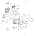
- FIG. 1 is an exploded perspective view of a main part of a vehicle to which a cover structure according to an embodiment of the present invention is applied.
- FIG. 2 is a perspective view showing the cover member.
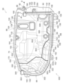
- FIG. 3 is a bottom view showing the lid portion of the cover member.
- FIG. 4 is a rear view showing the cover body of the cover member.
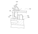
- FIG. 5 is a cross-sectional view taken along line VV in FIG.
- FIG. 6 is an explanatory diagram showing the left wall surface of the cover body as viewed from the inside.
- FIG. 7 is a perspective view showing an upper end portion of the left side wall component.
- FIG. 8 is a cross-sectional view of the main part showing a portion where the pipe is inserted into the cover member.
- cover structure 10 for a vehicle air conditioning system 20 (hereinafter sometimes simply referred to as “air conditioning system 20") according to an embodiment of the present invention is applied will be described.
- FIG. 1 is an exploded perspective view of the main parts of the vehicle 12 to which the cover structure 10 according to an embodiment of the present invention is applied.
- the X-axis is the vehicle length direction (front-rear direction)
- the Y-axis is the vehicle width direction (left-right direction)
- the Z-axis is the vehicle height direction (up-down direction).
- the X-axis, Y-axis, and Z-axis are mutually perpendicular.
- the vehicle 12 has an engine room 14 (a motor room in the case of an electric vehicle) as a driving source room, a passenger compartment 16, a partition wall 18, a vehicle air conditioner 20 (hereinafter simply referred to as the "air conditioner 20"), and a cover member 22.
- engine room 14 a motor room in the case of an electric vehicle
- passenger compartment 16 a passenger compartment 16
- partition wall 18 a vehicle air conditioner 20
- cover member 22 a cover member 22.
- the engine room 14 is provided at the front of the vehicle 12.
- the engine room 14 houses an engine (not shown) or an electric motor (not shown) as a drive source for driving the drive wheels (not shown) of the vehicle 12.
- the passenger compartment 16 is located behind the engine room 14. That is, the engine room 14 and the passenger compartment 16 are arranged side by side in the fore-and-aft direction of the vehicle 12. Passengers ride in the passenger compartment 16.
- the partition 18 separates the engine room 14 from the passenger compartment 16. In other words, the partition 18 separates the inside and outside of the passenger compartment 16. The partition 18 prevents noise from within the engine room 14 or noise from outside the vehicle 12 from entering the passenger compartment 16. An opening 30 is provided in the partition 18.
- the air conditioner 20 has an HVAC (heating ventilation and air conditioning) unit 40 and a refrigeration cycle circuit (not shown).
- HVAC heating ventilation and air conditioning
- the HVAC unit 40 is the unit through which the air used for air conditioning passes.
- the HVAC unit 40 has a case 42, an air conditioning device main body 44, an inside/outside air switching device 46, and a blower 48 equipped with a blower motor BM as a motor.
- HVAC unit 40 In a typical air conditioning system, all of the components of the HVAC unit 40 are located at the front of the passenger compartment 16 (behind the bulkhead 18) and are covered from above by the instrument panel (not shown), making them hidden from view to the passengers in the passenger compartment 16.
- the HVAC unit 40 is arranged separately in the engine room 14 and the passenger compartment 16, and is connected through an opening 30 in the partition wall 18.
- the blower 48 and the evaporator of the refrigeration cycle circuit or the heating equipment are provided in the engine compartment 14, and other components such as the inside/outside air switching device 46 are provided in the passenger compartment 16.
- the air conditioning unit 20 disposed within the passenger compartment 16 protrudes into the engine compartment 14 through the opening 30 in the bulkhead 18, and the air conditioning unit 20 expands the space within the passenger compartment 16 by disposing some of its components within the engine compartment 14.
- the case 42 houses the blower 48 and an evaporator (not shown).
- the case 42 defines an internal space through which the air used for air conditioning passes.
- the blower 48 which is disposed in the engine room 14, is driven by a blower motor BM.
- the blower 48 draws air from within the passenger compartment 16 and outside air into the HVAC unit 40.
- the air conditioning unit main body 44 has a front portion 44a and a rear portion 44b.
- the front portion 44a is disposed in the engine compartment 14.
- the front portion 44a houses an evaporator (not shown).
- the rear portion 44b is housed in the passenger compartment 16.
- the rear portion 44b is provided with an air outlet switching device (not shown) that switches which air outlet in the passenger compartment 16 air is blown out from.
- the inside/outside air switching device 46 has an inside air intake 46a, an outside air intake 46b, and a filter 46c. Air from inside the passenger compartment 16 is taken in through the inside air intake 46a. Air from outside the vehicle 12 (outside air) is taken in through the outside air intake 46b. The inside/outside air switching device 46 switches whether air is taken in through the inside air intake 46a or the outside air intake 46b.
- the filter 46c is removably attached inside the inside/outside air switching device 46.
- the filter 46c removes fine particles from the air taken into the HVAC unit 40 by the blower 48, purifying the air.
- the refrigeration cycle circuit (not shown) described above includes a compressor (not shown), a condenser (not shown), an expansion valve (not shown), an evaporator (not shown), a heater (not shown), etc.
- the compressor compresses the gas phase refrigerant to high temperature and pressure
- the condenser condenses and liquefies the refrigerant by heat exchange with outside air
- the expansion valve reduces the pressure of the liquid phase refrigerant and expands it
- the evaporator evaporates the refrigerant by heat exchange with the air used for air conditioning.
- the evaporator (not shown) is provided in the HVAC unit 40 and cools and dehumidifies the air supplied to the vehicle interior 16 by exchanging heat with the refrigerant.
- the cover member 22 is provided in the engine compartment 14 and attached to the partition wall 18. The cover member 22 is attached from the front of the vehicle interior 16 toward the rear of the vehicle.
- a soundproofing member 70 (see Figs. 3 and 4), which is an example of a damping member, is provided along the inner surface of the cover member 22.
- the soundproofing member 70 has at least one of a blocking function that blocks sound and a sound absorbing function that absorbs sound.
- the soundproofing member 70 has both a blocking function and a sound absorbing function to dampen sound.
- the soundproofing member 70 is made of, for example, foamed urethane, foamed rubber, etc.
- the soundproofing member 70 may also be configured to have an air layer inside. It may also be configured to have an uneven surface.
- the soundproofing member 70 is configured by appropriately selecting the material, structure, shape, and other examples exemplified above, taking into consideration the degree to which it is desired to suppress the intrusion of noise from outside the vehicle cabin and other required specifications.
- a vibration-damping member that suppresses vibrations may be provided along the inner surface of the cover member 22.
- the damping member may have at least one of the above-mentioned blocking function or sound absorbing function in addition to the vibration-damping function that suppresses vibrations.
- the soundproofing member 70 is composed of a plurality of divided components 72, 150, 200, 320, 500 (see Figures 3 and 4).
- the soundproofing member 70 provided along the inner surface of the cover body 50 of the cover member 22 is formed by the components 150, 200, 320, 500.
- the soundproofing member 70 provided along the inner surface of the lid portion 52 of the cover member 22 is formed by the component 72.
- the cover member 22 conceals some of the components of the air conditioning system 20 that protrude into the engine room 14, such as the blower 48 or the evaporator (not shown), and the opening 30 in the partition wall 18.
- the cover member 22 prevents noise from within the engine room 14 or noise from outside the vehicle 12 from entering the passenger compartment 16 through the opening 30.
- the cover member 22 has a cover body 50 and a lid portion 52.
- the cover body 50 When the cover body 50 is attached to the bulkhead 18, it forms an upwardly opening storage space 54 together with the bulkhead 18.
- the lid portion 52 is detachably attached to the cover body 50 and closes the upper opening 50a of the cover body 50.
- the opening 30 is open in the bulkhead 18, when the lid portion 52 is attached to the cover member 22, the engine room 14 and the passenger compartment 16 are completely isolated by the bulkhead 18, the cover body 50, and the lid portion 52.
- the cover body 50 may be attached directly to the bulkhead 18 or attached to the bulkhead 18 via another member, so long as the engine room 14 and the passenger compartment 16 are completely isolated.
- the blower 48 can be accessed through the upper opening 50a of the cover body 50, allowing the worker to easily perform maintenance on the blower 48.
- Fig. 2 is a perspective view showing the cover member 22.
- Fig. 2 shows the state in which the soundproofing member 70 has been removed.
- Fig. 3 is a bottom view showing the lid portion 52 of the cover member 22.
- Fig. 4 is a rear view showing the cover body 50 of the cover member 22.
- Fig. 5 is a V-V cross-sectional view in Fig. 4.
- Fig. 6 is an explanatory diagram showing the left side wall surface 82 of the cover body 50 as viewed from the inside.
- Fig. 7 is a perspective view showing the upper end portion of the left side wall component member 200.
- Fig. 8 is a cross-sectional view of the main part showing the portion where the piping is inserted into the cover member 22.
- the lid portion 52 is formed, for example, from a synthetic resin plate material.
- the lid portion 52 is formed in a horizontally elongated shape.
- the lid portion 52 has an inclined portion 52a that is inclined so as to become lower toward the front of the vehicle (see FIG. 1).
- the lid portion 52 is also formed in a shape that avoids interference with structures disposed in the engine compartment 14.
- a standing wall 60 is formed on the periphery of the lid portion 52, extending from the inner surface in the thickness direction of the lid portion 52.
- a flat surface 62 extends inward from the tip of the standing wall 60.
- a number of tongues 64 extend from the outer surface at the end of the standing wall 60. Each tongue 64 has a through hole 66 formed therein.
- the lid portion 52 is provided with a lid-side component 72 that constitutes a soundproofing member 70 .
- the lid side component 72 has a shape that corresponds to the inner surface of the lid portion 52, and the lid side component 72 adheres closely to the inner surface of the lid portion 52.
- the lid-side component 72 has a predetermined thickness.
- the lid-side component 72 has a wall portion 74 that extends along the upright wall 60 of the lid portion 52.
- the wall portion 74 is disposed along the upright wall 60 of the lid portion 52 and reaches the bottom of the flat surface 62.
- the cover body 50 is formed of, for example, a synthetic resin.
- the cover body 50 has a horizontally elongated bottom surface 80 and a left side wall surface 82 extending upward from the left edge of the bottom surface 80.
- the cover body 50 has a right side wall surface 84 extending upward from the right edge of the bottom surface 80, and a front wall surface 86 that connects the left side wall surface 82 and the right side wall surface 84 and has a lower edge connected to the bottom surface 80.
- the bottom surface 80, left side wall surface 82, right side wall surface 84, and front wall surface 86 of the cover body 50 are formed with projections and recesses to avoid interference with structures arranged in the engine room 14.
- the upper edge of the cover body 50 has lid fixing pieces 88 extending from the outer surface at positions corresponding to the tongue pieces 64 of the lid portion 52.
- Each lid fixing piece 88 has a fixing hole 90 formed therein.
- the cover body 50 is configured so that, with the top of the cover body 50 covered by the lid portion 52, the lid portion 52 can be fixed by fastening a bolt and nut that pass through the through hole 66 of the tongue piece 64 in the lid portion 52 and the fixing hole 90 of the lid fixing piece 88.
- the rear edge of the cover body 50 has multiple body fixing pieces 100 extending from the outer surface.
- Each body fixing piece 100 has an insertion hole 102 formed therein. This allows the cover body 50 to be fixed to the partition wall 18 by screws inserted into the insertion holes 102 of each body fixing piece 100.
- a first front wall convex portion 110 and a second front wall convex portion 112 that protrude inward are formed on the front wall surface 86 to avoid interference with structures arranged in the engine room 14.
- the end faces of the first front wall convex portion 110 and the second front wall convex portion 112 are flat.
- the second front wall convex portion 112 protrudes inward further than the first front wall convex portion 110.
- a flat first inclined surface 116 is formed between the general surface 114 of the front wall surface 86 (the portion other than the first front wall convex portion 110 and the second front wall convex portion 112) and the first convex surface 110a of the first front wall convex portion 110.
- a flat second inclined surface 118 is formed between the first convex surface 110a and the second convex surface 112a of the second front wall convex portion 112.
- a wiring hole 120 is formed in the center of the upper edge of the front wall surface 86, through which the wiring of the blower motor BM of the blower 48 passes.
- a wiring hole flange 122 is formed on the inner surface of the front wall surface 86, extending from the opening edge of the wiring hole 120.
- a vertically elongated hole 124 and a horizontally elongated hole 126 are formed on the sides of the wiring hole 120 in the front wall surface 86, through which refrigerant pipes are inserted to allow the refrigerant to flow.
- a vertically elongated hole flange 128 is formed on the inner surface of the front wall surface 86, extending from the opening edge of the vertically elongated hole 124.
- a horizontally elongated hole flange 130 is formed on the inner surface of the front wall surface 86, extending from the opening edge of the horizontally elongated hole 126.
- a heater hole 132 through which a heater tube is inserted is formed in the second front wall protrusion 112 (see FIG. 2) formed in the front wall surface 86 near the left side wall surface 82.
- a heater hole flange 134 is formed on the inner surface of the front wall surface 86, extending from the opening edge of the heater hole 132.
- the first front wall protrusion 110 (see FIG. 2) formed on the front wall surface 86 near the bottom surface 80 has drainage holes 136, 138 through which drainage pipes are inserted.
- the inner surface of the front wall surface 86 has drainage hole flanges 140, 142 extending from the opening edges of each drainage hole 136, 138.
- the upper edge of the front wall surface 86 is formed with a front wall flange portion 144 extending from the inner surface.
- a front wall component 150 that constitutes the soundproofing member 70 is provided on the front wall surface 86 .
- the front wall component 150 has a shape that corresponds to the unevenness of the inner surface of the front wall surface 86, and fits closely to the inner surface of the front wall surface 86.
- the front wall component 150 has a flat general portion 162 that adheres to the general surface 114 (see FIG. 2) of the front wall surface 86, and a flat first inclined portion 164 that adheres to the first inclined surface 116 (see FIG. 2) of the front wall surface 86.
- the front wall component 150 also has a flat first convex portion 166 that adheres to the first convex surface 110a (see FIG. 2) of the first front wall convex portion 110 of the front wall surface 86, and a flat second inclined portion 168 that adheres to the second inclined surface 118 (see FIG. 2) of the front wall surface 86.
- the front wall component 150 also has a flat second convex portion 169 that adheres to the second convex surface 112a (see FIG. 2) of the second front wall convex portion 112 of the front wall surface 86.
- the upper edge of the front wall component 150 has a shape that conforms to the front wall flange portion 144.
- the lower edge of the front wall component 150 has a shape that conforms to the bottom surface 80.
- the left edge of the front wall component 150 has a shape that conforms to the left side wall surface 82.
- the right edge of the front wall component 150 has a shape that conforms to the right side wall surface 84.
- the left side wall surface 82 and the right side wall surface 84 restrict the left-right movement of the front wall component 150.
- the front wall component 150 has a predetermined thickness, and is formed so that the thickness dimension of the upper end where the lid portion 52 is attached is thicker than the other portions.
- the front wall component 150 has a wiring opening 152 formed in a portion corresponding to the wiring hole 120.
- the opening edge of the wiring opening 152 surrounds the wiring hole flange 122 of the front wall surface 86.
- the front wall component 150 has a refrigerant opening 154 formed in a portion corresponding to the vertical hole 124 and the horizontal hole 126.
- the opening edge of the refrigerant opening 154 surrounds the vertical hole flange 128 and the horizontal hole flange 130.
- the front wall component 150 also has a heater opening 156 formed in a location corresponding to the heater hole 132.
- the opening edge of the heater opening 156 surrounds the heater hole flange 134.
- the front wall component 150 has drainage openings 158, 160 formed at locations corresponding to the drainage holes 136, 138.
- the drainage openings 158, 160 surround the drainage hole flanges 140, 142.
- the front wall component 150 is formed so that, when the cover body 50 is attached to the partition wall 18, the thickness dimension of the adjacent portion KB, which is located near the blower motor BM serving as the motor for the blower 48 in the air conditioning unit 20, is thicker than other portions.
- the right edge of the front wall component 150 has a first front straight portion 170 that extends in a straight line from the upper edge, a second front straight portion 172 that extends in a straight line diagonally from the first front straight portion 170, and a third front straight portion 174 that extends in a straight line downward from the second front straight portion 172.
- the left edge of the front wall component 150 that is located on the left side wall surface 82 side is formed in a straight line along the left side wall surface 82 (not shown).
- the upper edge of the front wall component 150 that is located on the front wall flange portion 144 side is formed in a straight line along the front wall flange portion 144 (not shown).
- a left wall flange portion 190 extending from the inner surface is formed at the upper edge of the left side wall surface 82.
- the left wall flange portion 190 is continuous with the front wall flange portion 144.
- a left wall rear flange portion 192 extending from the inner surface is formed at the rear edge of the left side wall surface 82.
- a rectangular left seal 194 is provided at the upper end of the left wall rear flange 192.
- the left seal 194 is a sponge-like part, and is made, for example, of foamed EPDM (ethylene propylene diene rubber). This left seal 194 adheres closely to the lid 52 attached to the cover body 50 and to the partition wall 18 to which the cover body 50 is fixed.
- a left side wall component 200 that constitutes the soundproofing member 70 is provided on the left side wall surface 82 .
- the left side wall component 200 has a shape that corresponds to the inner surface of the left side wall 82 and fits closely to the inner surface of the left side wall 82.
- the upper edge of the left side wall component 200 is formed in a straight line along the left wall flange portion 190.
- the lower edge of the left side wall component 200 is formed in a straight line along the bottom surface 80.
- the front edge of the left side wall component 200 is formed to have a shape that follows the surface of the front wall component 150.
- the front edge of the left side wall component 200 is composed of multiple straight line portions (not shown) that are formed in straight lines that match the surface shape of the front wall component 150.
- the rear edge of the left side wall component 200 is formed in a straight line along the left wall rear flange portion 192. As a result, the movement of the left side wall component 200 in the front-rear direction is restricted by the front wall component 150 and the left wall rear flange portion 192.
- the left side wall component 200 has a predetermined thickness.
- the left side wall component 200 is formed so that the thickness dimension of the upper end where the lid portion 52 is attached is thicker than the other portions.
- a right wall flange portion 300 extending from the inner surface is formed at the upper edge of the right side wall surface 84.
- the right wall flange portion 300 is continuous with the front wall flange portion 144.
- the front wall flange portion 144, the left wall flange portion 190, and the right wall flange portion 300 are continuously formed at the upper edge of the cover body 50.
- a right wall rear flange portion 302 is formed on the rear edge of the right side wall surface 84, extending from the inner surface.
- a rectangular right seal material 304 is provided at the upper end of the right wall rear flange portion 302.
- the right seal material 304 is a sponge-like part, and is made of, for example, foamed EPDM (ethylene propylene diene rubber). This right seal material 304 adheres closely to the lid portion 52 attached to the cover body 50 and to the partition wall 18 to which the cover body 50 is fixed.
- the lower part of the right side wall 84 is formed with a bottom inclined surface 310 that slopes gently downward toward the bottom surface 80, and a front inclined surface 312 that slopes gently upward from the bottom inclined surface 310 toward the front wall surface 86.
- a right side wall component member 320 that constitutes the soundproofing member 70 is provided on the right side wall surface 84 .
- the right side wall component 320 has a shape that corresponds to the inner surface of the right side wall 84 and fits closely to the inner surface of the right side wall 84.
- the lower part of the right side wall component 320 is formed in a shape that follows the bottom inclined surface 310 (see FIG. 2) of the right side wall surface 84, and has a bottom inclined portion 322 that comes into close contact with the bottom inclined surface 310.
- the edge 322a of the bottom inclined portion 322 is formed in a straight line.
- the lower part of the right side wall component 320 is formed in a shape that follows the front inclined surface 312 (see FIG. 2) of the right side wall surface 84, and has a front inclined portion 324 that comes into close contact with the front inclined surface 312.
- the right side wall component 320 has a predetermined thickness.
- the right side wall component 320 is formed so that the thickness dimension of the upper end where the lid portion 52 is attached is thicker than the other portions.
- the front wall component 150, the left side wall component 200, and the right side wall component 320 are made thick at their upper ends, which are close to the passengers in the passenger compartment 16 and through which engine noise can easily penetrate, enhancing the soundproofing effect.
- the upper edge of the right side wall component 320 is formed in a straight line along the right wall flange portion 300.
- the upper edge of the right side wall component 320 overlaps with the right wall flange portion 300.
- the bottom side inclined portion 322 is in close contact with the bottom side inclined surface 310 (see FIG. 2).
- the front inclined portion 324 of the lower portion of the right side wall component 320 is in close contact with the front inclined surface 312 (see FIG. 2).
- the right side wall component 320 is restricted from moving in the up and down direction by the right wall flange portion 300 and the bottom inclined surface 310.
- the front edge of the right side wall component 320 has a first left wall surface straight portion 330 extending linearly from the upper edge side, a second left wall surface straight portion 332 extending linearly diagonally from the first left wall surface straight portion 330, and a third left wall surface straight portion 334 extending linearly downward from the second left wall surface straight portion 332.
- the first left wall surface straight portion 330 is provided at a position corresponding to the first front surface straight portion 170 of the front wall component member 150, and the first left wall surface straight portion 330 is overlapped along the first front surface straight portion 170.
- the second left wall surface straight portion 332 is provided at a position corresponding to the second front surface straight portion 172 of the front wall component member 150, and the second left wall surface straight portion 332 is overlapped along the second front surface straight portion 172.
- the third left wall surface straight portion 334 is provided at a position corresponding to the third front surface straight portion 174 of the front wall component member 150, and the third left wall surface straight portion 334 is overlapped along the third front surface straight portion 174.
- the rear edge of the right side wall component 320 is formed in a straight line along the right wall rear flange portion 302.
- the rear edge of the right side wall component 320 overlaps with the right wall rear flange portion 302.
- the right side wall component 320 is restricted from moving in the fore-and-aft direction by the front straight portions 170, 172, 174 of the front wall component 150 and the right wall rear flange portion 302.
- the bottom surface 80 is formed with a first bottom surface convex portion 400 and a second bottom surface convex portion 402 that protrude inward to avoid interference with structures arranged in the engine room 14 (see FIG. 2).
- a bottom rear flange portion 404 is formed at the rear edge of the bottom surface 80, extending from the inner surface.
- the bottom rear flange portion 404 is continuous with the left wall rear flange portion 192 and the right wall rear flange portion 302.
- the left wall rear flange portion 192, the bottom rear flange portion 404, and the right wall rear flange portion 302 are formed continuously at the rear edge of the cover body 50.
- a bottom surface component 500 that constitutes the soundproofing member 70 is provided on the bottom surface 80 .
- the bottom surface component 500 has a shape that corresponds to the uneven bottom surface 80, and adheres closely to the inner surface of the bottom surface 80.
- the bottom surface component 500 has a predetermined thickness.
- the left edge of the bottom surface component 500 is formed in a straight line along the surface of the left side wall component 200.
- the left edge of the bottom surface component 500 overlaps with the left side wall component 200.
- the right edge 500a of the bottom component 500 is formed in a straight line along the edge 322a of the bottom inclined portion 322 of the right side wall component 320.
- the right edge 500a of the bottom component 500 overlaps with the edge 322a of the bottom inclined portion 322 of the right side wall component 320.
- the bottom surface component 500 is restricted from moving in the left-right direction by the edge 322a of the bottom inclined portion 322 of the left side wall component 200 and the right side wall component 320.
- the front edge of the bottom surface component 500 has a portion corresponding to the general portion 162 of the front wall component 150, a portion corresponding to the first convex portion 166 of the front wall component 150, and a portion corresponding to the second convex portion 169 of the front wall component 150.
- the front edge of the bottom component 500 is formed with a first bottom straight portion 502 that corresponds to the general portion 162 of the front wall component 150 in a straight line, and the first bottom straight portion 502 overlaps with the general portion 162 of the front wall component 150.
- the front edge of the bottom component 500 is formed with a second bottom straight portion 504 that corresponds to the first inclined portion 164 of the front wall component 150 in a straight line, and the second bottom straight portion 504 overlaps with the first inclined portion 164 of the front wall component 150.
- the front edge of the bottom component 500 has a third bottom straight portion 506 formed in a straight line that corresponds to the first convex portion 166 of the front wall component 150, and the third bottom straight portion 506 overlaps with the first convex portion 166 of the front wall component 150.
- the front edge of the bottom component 500 has a fourth bottom straight portion 508 formed in a straight line that corresponds to the second inclined portion 168 of the front wall component 150, and the fourth bottom straight portion 508 overlaps with the second inclined portion 168 of the front wall component 150 (not shown).
- the front edge of the bottom surface component 500 is formed with a fifth bottom surface straight portion 509 that corresponds to the second convex portion 169 of the front wall component 150 in a straight line, and the fifth bottom surface straight portion 509 overlaps with the second convex portion 169 of the front wall component 150.
- the rear edge of the bottom component 500 is formed in a straight line along the bottom rear flange portion 404.
- the rear edge of the bottom component 500 overlaps with the bottom rear flange portion 404.
- the movement of the bottom component 500 in the front-to-rear direction is restricted by the front wall component 150 and the bottom rear flange portion 404.
- each of the components 150, 200, 320, 500 that come into contact with the adjacent components (150, 200, 320, 500) are formed in a straight line. Also, in the combined state 600 in which the components 150, 200, 320, 500 are combined, the ends of one adjacent component (150, 200, 320, 500) and the other adjacent component (150, 200, 320, 500) overlap each other.
- a weather strip 610 (see FIG. 5 ) that is in intimate contact with the flat surface 62 of the lid portion 52 is provided on the upper edge of the cover body 50 across the front wall flange portion 144, the left wall flange portion 190, and the right wall flange portion 300 (not shown).
- a weather strip 610 that is in intimate contact with the partition wall 18 is provided on the rear edge of the cover body 50 across the left wall rear flange portion 192, the bottom surface rear flange portion 404, and the right wall rear flange portion 302 (not shown).
- the weather strip 610 is provided on the left wall flange portion 190 of the cover body 50. Note that the weather strip 610 is also provided in other locations in the same manner as described below.
- the left wall flange portion 190 of the cover body 50 has clip insertion holes 620 at multiple locations. Hooks 622a at the tips of clips 622 provided on the weather strip 610 are inserted and engaged into each clip insertion hole 620.
- the weatherstrip 610 is made of, for example, a rubber material.
- the weatherstrip 610 has a hollow triangular cross section.
- An extension piece 624 is formed on one of the sloping surfaces of the weatherstrip 610, extending approximately perpendicular to the sloping surface.
- the top 626 protrudes upward.
- the extension piece 624 extends diagonally outward in the direction in which the top 626 protrudes.
- a groove 628 in which the tip of the clip 622 is placed is formed on the end face 200a of the left side wall component 200, which is disposed below the left wall flange portion 190 and formed thick.
- a high portion 630 that is higher than the groove portion 628 is provided on the end face 200a of the left side wall component 200, closer to the left side wall surface 82 than the groove portion 628 (see Figures 5 and 7).
- this high portion 630 is disposed between the tip of the clip 622 and the left side wall surface 82 with the left side wall component 200 disposed along the inner surface of the left side wall surface 82. As a result, the tip of the clip 622 abuts against the high portion 630, preventing the left side wall component 200 disposed along the left side wall surface 82 from falling over.
- a clip 622 is provided at the upper end of the left side wall surface 82, which is the end of the cover body 50 that surrounds part of the upper opening 50a, as a support member that supports the end of the left side wall component 200 along the left side wall surface 82 of the cover body 50.
- the worker When providing the soundproofing member 70 to the cover body 50, the worker first attaches the front wall constituent member 150 constituting the soundproofing member 70 to the inner surface of the front wall surface 86. As a result, the front wall constituent member 150 is restricted in its vertical movement by the front wall flange portion 144 and the bottom surface 80, and is restricted in its horizontal movement by the left side wall surface 82 and the right side wall surface 84. In addition, the front wall constituent member 150 is prevented from falling over by the clip 622.
- the worker attaches the left side wall component 200, which constitutes the soundproofing member 70, to the inner surface of the left side wall surface 82, and the left wall flange portion 190 and the bottom surface 80 restrict the left side wall component 200 from moving in the vertical direction. In addition, the left side wall component 200 is prevented from falling over by the clip 622.
- the worker presses the end face of the front edge of the left side wall component 200 against the surface of the front wall component 150 to prevent the left edge of the front wall component 150 from falling over.
- the worker attaches the right side wall component 320, which constitutes the soundproofing member 70, to the inner surface of the right side wall surface 84, and restricts the vertical movement of the right side wall component 320 with the right wall flange portion 300 and the bottom inclined surface 310.
- the worker also uses the clip 622 to prevent the right side wall component 320 from falling over.
- the worker presses the end face of the front edge of the right side wall component 320 against the surface of the front wall component 150 to prevent the right edge of the front wall component 150 from falling over.
- the worker attaches the bottom surface component 500 that constitutes the soundproofing member 70 to the inner surface of the bottom surface 80.
- the worker restricts the movement of the lower end of the left side wall component 200 by overlapping and pressing the end face of the left edge of the bottom component 500 against the surface of the left side wall component 200.
- the worker also restricts the movement of the lower end of the right side wall component 320 by overlapping and pressing the end face of the right edge 500a of the bottom component 500 against the surface of the right side wall component 320.
- the worker also restricts the movement of the lower end of the front wall component 150 by overlapping and pressing the end face of the front edge of the bottom component 500 against the surface of the front wall component 150.
- the worker When attaching the cover body 50 to the bulkhead 18, the worker inserts the wiring, refrigerant pipes, heater pipes, drain pipes, etc., connected to the air conditioner 20 through the holes 120, 124, 126, 132, 136, 138 formed in the cover body 50.
- a seal member 702 is provided on the outer periphery of the refrigerant pipe 700 that is inserted into the vertical hole 124. This seal member 702 adheres closely to the vertical hole flange 128 that extends from the opening edge of the vertical hole 124 and to the portion of the front wall component 150 that surrounds the vertical hole flange 128.
- This sealing member 702 is made of foamed PE (polyethylene) and foamed EPDM (ethylene propylene diene rubber), and the sealing member 702 adheres closely to the vertically elongated hole flange 128 and the front wall component 150, ensuring sound insulation, watertightness, and airtightness.
- PE polyethylene
- EPDM ethylene propylene diene rubber
- the cover structure 10 of the vehicle air conditioner 20 includes a partition wall 18 that separates the passenger compartment 16 in which the occupants sit from the outside of the passenger compartment 16 and has an opening 30 in which the vehicle air conditioner 20 is located, and a cover member 22 that covers at least a part of the vehicle air conditioner 20 located outside the passenger compartment 16 and the opening 30.
- the cover structure 10 of the vehicle air conditioner 20 includes a damping member that is provided inside the cover member 22 and damps sound.
- the damping member is made up of multiple components 150, 200, 320, 500 that come into contact with each other and are assembled together to form the damping member.
- a damping member that attenuates sound is provided on the inside of the cover member 22 that covers at least a portion of the vehicle air conditioning device 20 provided outside the passenger compartment 16 and the opening 30.
- This damping member is composed of multiple divided components 150, 200, 320, 500. Therefore, even if the inside of the cover member 22 is formed into a surface shape that includes a curved surface or a high and low surface, the multiple components 150, 200, 320, 500 can be arranged in contact with each other at corresponding locations according to the surface shape of the inside of the cover member.
- the cover structure 10 for the vehicle air conditioner 20 is able to suppress the intrusion of outside noise into the vehicle compartment 16 through the opening 30 for the vehicle air conditioner 20 formed in the partition wall 18 that separates the inside and outside of the vehicle compartment, compared to covering the opening with a resin cover made of a single material.
- the soundproofing member 70 which is an example of a damping member, has a blocking function that blocks sound and a sound absorbing function that absorbs sound. Therefore, the blocking function of the soundproofing member 70 prevents noise outside the vehicle cabin from entering the vehicle compartment 16, and the sound generated by the motor and other components inside the cover member 22 is absorbed by the sound absorbing function, preventing the noise from entering the vehicle cabin 16.
- the components 72, 150, 200, 320, and 500 that make up the soundproofing member 70 which is an example of a damping member, can be arranged closely and without gaps on the inner surface of the cover member 22. Therefore, even if the cover member 22 is made thin to reduce weight, the cover member 22 can still provide the effect of suppressing noise from entering the vehicle interior 16.
- each component 150, 200, 320, 500 that contact adjacent components are formed in a straight line.
- each of the components 150, 200, 320, 500 it is possible to simplify the structure of each of the components 150, 200, 320, 500 compared to when the edges where adjacent components (150, 200, 320, 500) meet are formed with complex curves. In addition, it becomes easier to assemble the adjacent components (150, 200, 320, 500).
- adjacent components 150, 200, 320, 500
- the other component 150, 200, 320, 500
- the ends of adjacent components overlap each other, making it possible to suppress sound leakage compared to when gaps are created between the ends of adjacent components (150, 200, 320, 500).
- the cover member 22 has a cover body 50 that forms an upper open storage space 54 while covering at least a portion of the vehicle air conditioner 20 and the opening 30, and a lid portion 52 that closes the upper opening 50a of the cover body 50.
- a clip 622 is provided as a support member that supports the ends of each component 150, 200, 320 along the side wall surfaces (82, 84, 86) of the cover body 50.
- clips 622 are provided at the ends of the cover body 50 to support the ends of the components 150, 200, 320 along the side wall surfaces (82, 84, 86) of the cover body 50. This makes it possible for the clips 622 to prevent the components 150, 200, 320 arranged along the side wall surfaces (82, 84, 86) from falling over.
- the clips 622 that support the ends of the components 150, 200, 320 are provided at the ends of the cover body 50 that surround a portion of the upper opening 50a. Therefore, the support positions of the clips 622 can be set at the ends of the components 150, 200, 320 that are formed to be thick. This makes it easier to configure the support structure compared to when the clips 622 support the ends of components that are formed to be thin.
- the cover member 22 also has a cover body 50 that, together with the partition wall 18, forms an upwardly opening storage space 54, and a lid portion 52 that closes the upper opening 50a of the cover body 50. Therefore, by opening the lid portion 52 and opening the upper opening 50a, maintenance of the vehicle air conditioner 20 becomes possible.
- a part of the vehicle air conditioner 20 located outside the passenger compartment 16 is equipped with a blower motor BM, which is the motor for the blower 48, and the soundproofing member 70 provided on the cover member 22 has a thicker thickness at the portion (KB) located near the blower motor BM than at other portions.
- a blower motor BM which is the motor for the blower 48
- the soundproofing member 70 provided on the cover member 22 has a thicker thickness at the portion (KB) located near the blower motor BM than at other portions.
- the blower motor BM which is the motor of the blower 48, generates noise during operation, and there is a risk that the generated noise may invade the vehicle interior 16. Therefore, by making the thickness dimension of the portion (KB) of the soundproofing member 70 located near the blower motor BM thicker than other portions, it is possible to reduce the intrusion of noise generated by the blower motor BM into the vehicle interior 16.
- soundproofing material 70 with sound-absorbing properties can increase the ability to absorb noise generated by the blower motor BM.
Landscapes
- Physics & Mathematics (AREA)
- Engineering & Computer Science (AREA)
- Mechanical Engineering (AREA)
- Acoustics & Sound (AREA)
- Thermal Sciences (AREA)
- Air-Conditioning For Vehicles (AREA)
- Vehicle Interior And Exterior Ornaments, Soundproofing, And Insulation (AREA)
- Body Structure For Vehicles (AREA)
Abstract
Description
カバー部材22は、エンジンルーム14内に設けられて隔壁18に取り付けられる。カバー部材22は、車室16よりも車両前方から車両後方に向かって取り付けられる。
図2及び図3に示すように、蓋部52は、例えば、合成樹脂の板材によって形成されている。蓋部52は、横長形状に形成されている。蓋部52は、車両前方に向かって低くなるように傾斜する傾斜部52aを有する(図1参照)。また、蓋部52は、エンジンルーム14に配置された構造物との干渉を回避するための形状に形成されている。
この蓋部52には、防音部材70を構成する蓋側構成部材72が設けられている。
図2及び図4に示すように、カバー本体50は、例えば、合成樹脂によって形成されている。カバー本体50は、横長形状の底面80と、底面80の左縁から上方へ向けて延出する左側壁面82と、を有する。カバー本体50は、底面80の右縁から上方へ向けて延出する右側壁面84と、左側壁面82及び右側壁面84を連設するとともに下縁が底面80に連設された前壁面86と、を有する。
図2に示すように、前壁面86には、エンジンルーム14に配置された構造物との干渉を回避するために内側に突出した第一前壁凸部110及び第二前壁凸部112が形成されている。第一前壁凸部110及び第二前壁凸部112の端面は平坦である。第二前壁凸部112は、第一前壁凸部110よりも内側に突出する。
前壁面86には、防音部材70を構成する前壁構成部材150が設けられている。
左側壁面82の上縁には、内面から延出する左壁フランジ部190が形成されている。左壁フランジ部190は、前壁フランジ部144と連続する。左側壁面82の後縁には、内面から延出する左壁後フランジ部192が形成されている。
左側壁面82には、防音部材70を構成する左側壁構成部材200が設けられている。
右側壁面84の上縁には、内面から延出する右壁フランジ部300が形成されている。右壁フランジ部300は、前壁フランジ部144と連続する。これにより、カバー本体50の上縁には、前壁フランジ部144、左壁フランジ部190、及び右壁フランジ部300が連続して形成されている。
図4に示すように、この右側壁面84には、防音部材70を構成する右側壁構成部材320が設けられている。
底面80には、エンジンルーム14に配置された構造物との干渉を回避するために内側に突出した第一底面凸部400及び第二底面凸部402が形成されている(図2参照)。
底面80には、防音部材70を構成する底面構成部材500が設けられている。
カバー本体50の上縁には、蓋部52の平坦面62と密着するウェザーストリップ610(図5参照)が、前壁フランジ部144、左壁フランジ部190、及び右壁フランジ部300に渡って設けられる(図示省略)。また、カバー本体50の後縁には、隔壁18に密着されるウェザーストリップ610が、左壁後フランジ部192、底面後フランジ部404、及び右壁後フランジ部302に渡って設けられる(図示省略)。
カバー本体50に防音部材70を設ける際に、作業者は、先ず、防音部材70を構成する前壁構成部材150を前壁面86の内面に装着する。これにより、前壁構成部材150は、前壁フランジ部144と底面80とによって上下方向の移動が規制されるとともに、左側壁面82と右側壁面84とによって左右方向の移動が規制される。また、前壁構成部材150は、クリップ622によって倒れが抑制される。
Claims (5)
- 乗員が乗車する車室の内外を隔てるとともに、前記車室の内外に渡って設けられた車両用空調装置が配置された開口部を有した、隔壁と、
前記車室の外に設けられた前記車両用空調装置の少なくとも一部と前記開口部とを覆うカバー部材と、
を備える車両用空調装置のカバー構造であって、
前記カバー部材の内側に設けられ、音を減衰する減衰部材を備え、
前記減衰部材は、互いに接触して組み合った状態で前記減衰部材を形成する複数の構成部材で構成される、
車両用空調装置のカバー構造。 - 請求項1に記載の車両用空調装置のカバー構造であって、
前記構成部材は、隣り合う他の前記構成部材と接する縁部が直線状に形成される、
車両用空調装置のカバー構造。 - 請求項2に記載の車両用空調装置のカバー構造であって、
前記組み合った状態において隣り合う一方の前記構成部材と他方の前記構成部材とは、互いに端部が重なり合う、
車両用空調装置のカバー構造。 - 請求項1に記載の車両用空調装置のカバー構造であって、
前記カバー部材は、前記車両用空調装置の少なくとも一部と前記開口部とを覆った状態で上方が開口した収容空間を形成するカバー本体と、前記カバー本体の上部の開口を閉鎖する蓋部とを有し、
前記上部の開口の一部を包囲する前記カバー本体の端部には、前記構成部材の端部を前記カバー本体の側壁面に沿うように支持する支持部材が設けられている、
車両用空調装置のカバー構造。 - 請求項1に記載の車両用空調装置のカバー構造であって、
前記車室の外に配置される前記車両用空調装置の一部は送風機のモータであって、
前記カバー部材に設けられる前記減衰部材は、前記モータの近くに配置される部位の厚みが他の部分よりも厚い、
車両用空調装置のカバー構造。
Priority Applications (2)
| Application Number | Priority Date | Filing Date | Title |
|---|---|---|---|
| CN202380084148.5A CN120344415A (zh) | 2022-12-14 | 2023-11-02 | 车辆用空调装置的罩构造 |
| EP23903141.2A EP4635761A4 (en) | 2022-12-14 | 2023-11-02 | VEHICLE AIR CONDITIONING UNIT LID STRUCTURE |
Applications Claiming Priority (2)
| Application Number | Priority Date | Filing Date | Title |
|---|---|---|---|
| JP2022-199523 | 2022-12-14 | ||
| JP2022199523A JP7705840B2 (ja) | 2022-12-14 | 2022-12-14 | 車両用空調装置のカバー構造 |
Publications (1)
| Publication Number | Publication Date |
|---|---|
| WO2024127843A1 true WO2024127843A1 (ja) | 2024-06-20 |
Family
ID=91485471
Family Applications (1)
| Application Number | Title | Priority Date | Filing Date |
|---|---|---|---|
| PCT/JP2023/039584 Ceased WO2024127843A1 (ja) | 2022-12-14 | 2023-11-02 | 車両用空調装置のカバー構造 |
Country Status (4)
| Country | Link |
|---|---|
| EP (1) | EP4635761A4 (ja) |
| JP (1) | JP7705840B2 (ja) |
| CN (1) | CN120344415A (ja) |
| WO (1) | WO2024127843A1 (ja) |
Citations (2)
| Publication number | Priority date | Publication date | Assignee | Title |
|---|---|---|---|---|
| JPS5712309U (ja) * | 1980-06-27 | 1982-01-22 | ||
| JP2019202755A (ja) | 2018-05-17 | 2019-11-28 | マレリ株式会社 | 車両用空調装置 |
Family Cites Families (2)
| Publication number | Priority date | Publication date | Assignee | Title |
|---|---|---|---|---|
| KR102707441B1 (ko) * | 2020-02-24 | 2024-09-19 | 한온시스템 주식회사 | 차량용 공조장치 |
| KR102298988B1 (ko) * | 2019-12-13 | 2021-09-06 | 현대자동차주식회사 | 분리형 공조장치의 정비성 및 차음성 개선 구조 |
-
2022
- 2022-12-14 JP JP2022199523A patent/JP7705840B2/ja active Active
-
2023
- 2023-11-02 CN CN202380084148.5A patent/CN120344415A/zh active Pending
- 2023-11-02 EP EP23903141.2A patent/EP4635761A4/en active Pending
- 2023-11-02 WO PCT/JP2023/039584 patent/WO2024127843A1/ja not_active Ceased
Patent Citations (2)
| Publication number | Priority date | Publication date | Assignee | Title |
|---|---|---|---|---|
| JPS5712309U (ja) * | 1980-06-27 | 1982-01-22 | ||
| JP2019202755A (ja) | 2018-05-17 | 2019-11-28 | マレリ株式会社 | 車両用空調装置 |
Non-Patent Citations (1)
| Title |
|---|
| See also references of EP4635761A1 |
Also Published As
| Publication number | Publication date |
|---|---|
| JP2024085148A (ja) | 2024-06-26 |
| EP4635761A4 (en) | 2026-03-25 |
| EP4635761A1 (en) | 2025-10-22 |
| JP7705840B2 (ja) | 2025-07-10 |
| CN120344415A (zh) | 2025-07-18 |
Similar Documents
| Publication | Publication Date | Title |
|---|---|---|
| US6178764B1 (en) | Air conditioning system | |
| JP4361438B2 (ja) | バッテリ冷却システム | |
| JP2001213139A (ja) | 車両用空気案内ダクト | |
| JP2000516880A (ja) | 一体型のブーツを備えた防音層 | |
| CN1936446B (zh) | 提高隔音的加热、通风和/或空调单元 | |
| US12090835B2 (en) | Arrangement of an air guiding element made of foam on a cooler element, and cooler element and air guiding element made of foam | |
| JP2008126800A (ja) | 自動車用空調装置 | |
| CN113525033B (zh) | 车辆空气调节系统 | |
| JP7705840B2 (ja) | 車両用空調装置のカバー構造 | |
| KR20190035528A (ko) | 흡음부, 차음된 차체를 제조하기 위한 방법, 및 자동차 | |
| JP4135436B2 (ja) | 車載空調ケースのドレンホース保護構造 | |
| US6808045B2 (en) | Secondary acoustic attenuator for vehicle | |
| JP3714382B2 (ja) | 車両の通風構造 | |
| JP3925544B2 (ja) | 車両用空調装置 | |
| JP4081877B2 (ja) | 空調装置 | |
| WO2023095585A1 (ja) | 車両用空調装置の排水構造 | |
| JPS5819054Y2 (ja) | 自動車用空調機器のハウジング構造 | |
| GB2369163A (en) | Sealing device between a partition and a fitting set in front of an opening formed in the partition | |
| JPH04349016A (ja) | 自動車の空気調和装置 | |
| JP4218332B2 (ja) | 車両空調ダクト構造 | |
| JP3864527B2 (ja) | 車両用空調装置 | |
| JP2019206948A (ja) | 車両の前部構造 | |
| JPS6216372Y2 (ja) | ||
| JP2585363Y2 (ja) | 自動車用インシュレータダッシュ | |
| WO2025013152A1 (ja) | ラゲッジサイドトリム |
Legal Events
| Date | Code | Title | Description |
|---|---|---|---|
| 121 | Ep: the epo has been informed by wipo that ep was designated in this application |
Ref document number: 23903141 Country of ref document: EP Kind code of ref document: A1 |
|
| WWE | Wipo information: entry into national phase |
Ref document number: 202380084148.5 Country of ref document: CN |
|
| WWE | Wipo information: entry into national phase |
Ref document number: 2023903141 Country of ref document: EP |
|
| NENP | Non-entry into the national phase |
Ref country code: DE |
|
| WWP | Wipo information: published in national office |
Ref document number: 202380084148.5 Country of ref document: CN |
|
| ENP | Entry into the national phase |
Ref document number: 2023903141 Country of ref document: EP Effective date: 20250714 |
|
| WWP | Wipo information: published in national office |
Ref document number: 2023903141 Country of ref document: EP |