WO2024157698A1 - ガス発生器及びエアバッグモジュール組立体 - Google Patents
ガス発生器及びエアバッグモジュール組立体 Download PDFInfo
- Publication number
- WO2024157698A1 WO2024157698A1 PCT/JP2023/046085 JP2023046085W WO2024157698A1 WO 2024157698 A1 WO2024157698 A1 WO 2024157698A1 JP 2023046085 W JP2023046085 W JP 2023046085W WO 2024157698 A1 WO2024157698 A1 WO 2024157698A1
- Authority
- WO
- WIPO (PCT)
- Prior art keywords
- housing
- gas
- temperature rise
- gas generator
- airbag
- Prior art date
- Legal status (The legal status is an assumption and is not a legal conclusion. Google has not performed a legal analysis and makes no representation as to the accuracy of the status listed.)
- Ceased
Links
Images


Classifications
-
- B—PERFORMING OPERATIONS; TRANSPORTING
- B60—VEHICLES IN GENERAL
- B60R—VEHICLES, VEHICLE FITTINGS, OR VEHICLE PARTS, NOT OTHERWISE PROVIDED FOR
- B60R21/00—Arrangements or fittings on vehicles for protecting or preventing injuries to occupants or pedestrians in case of accidents or other traffic risks
- B60R21/02—Occupant safety arrangements or fittings, e.g. crash pads
- B60R21/16—Inflatable occupant restraints or confinements designed to inflate upon impact or impending impact, e.g. air bags
- B60R21/26—Inflatable occupant restraints or confinements designed to inflate upon impact or impending impact, e.g. air bags characterised by the inflation fluid source or means to control inflation fluid flow
- B60R21/264—Inflatable occupant restraints or confinements designed to inflate upon impact or impending impact, e.g. air bags characterised by the inflation fluid source or means to control inflation fluid flow using instantaneous generation of gas, e.g. pyrotechnic
- B60R21/2644—Inflatable occupant restraints or confinements designed to inflate upon impact or impending impact, e.g. air bags characterised by the inflation fluid source or means to control inflation fluid flow using instantaneous generation of gas, e.g. pyrotechnic using only solid reacting substances, e.g. pellets, powder
-
- B—PERFORMING OPERATIONS; TRANSPORTING
- B60—VEHICLES IN GENERAL
- B60R—VEHICLES, VEHICLE FITTINGS, OR VEHICLE PARTS, NOT OTHERWISE PROVIDED FOR
- B60R21/00—Arrangements or fittings on vehicles for protecting or preventing injuries to occupants or pedestrians in case of accidents or other traffic risks
- B60R21/02—Occupant safety arrangements or fittings, e.g. crash pads
- B60R21/16—Inflatable occupant restraints or confinements designed to inflate upon impact or impending impact, e.g. air bags
- B60R21/26—Inflatable occupant restraints or confinements designed to inflate upon impact or impending impact, e.g. air bags characterised by the inflation fluid source or means to control inflation fluid flow
- B60R2021/2607—Inflatable occupant restraints or confinements designed to inflate upon impact or impending impact, e.g. air bags characterised by the inflation fluid source or means to control inflation fluid flow characterised by heating or heat insulating means, e.g. for use under extreme temperatures
-
- B—PERFORMING OPERATIONS; TRANSPORTING
- B60—VEHICLES IN GENERAL
- B60R—VEHICLES, VEHICLE FITTINGS, OR VEHICLE PARTS, NOT OTHERWISE PROVIDED FOR
- B60R21/00—Arrangements or fittings on vehicles for protecting or preventing injuries to occupants or pedestrians in case of accidents or other traffic risks
- B60R21/02—Occupant safety arrangements or fittings, e.g. crash pads
- B60R21/16—Inflatable occupant restraints or confinements designed to inflate upon impact or impending impact, e.g. air bags
- B60R21/26—Inflatable occupant restraints or confinements designed to inflate upon impact or impending impact, e.g. air bags characterised by the inflation fluid source or means to control inflation fluid flow
- B60R2021/26076—Inflatable occupant restraints or confinements designed to inflate upon impact or impending impact, e.g. air bags characterised by the inflation fluid source or means to control inflation fluid flow characterised by casing
Definitions
- the present invention relates to a gas generator and an airbag module assembly.
- gas generators have been widely known that house a gas generating agent in a housing, generate gas by burning the gas generating agent with the activation of an ignition device, and release the gas outside the housing.
- This type of gas generator is used, for example, to supply gas to airbags and seat belt retractors in automobiles.
- a gas generator When a gas generator is activated, the surface of the housing becomes hot due to the conduction of heat from the combustion of the gas generating agent. For example, when the gas generator is activated to inflate and deploy an airbag, if the airbag comes into contact with the hot housing, there is a concern that the airbag may melt or be otherwise thermally affected by components arranged around the housing.
- a gas generator has been disclosed that provides a heat insulating member on the surface of the housing to suppress the rise in the surface temperature of the housing (for example, Patent Document 1).
- the technology disclosed herein has been developed in consideration of the above-mentioned circumstances, and its purpose is to provide a technology that can more efficiently suppress the temperature rise of the housing after the gas generator is activated.
- the gas generator according to the present disclosure is a gas generator including: a gas generating agent that generates gas by combustion, a metal housing that accommodates the gas generating agent therein and has a gas exhaust hole formed therein for exhausting the gas generated by combustion of the gas generating agent to the outside, an ignition device that ignites the gas generating agent by activation, and a temperature rise suppression member that is provided in contact with the outer surface of the housing so as to cover at least a portion of the outer surface of the housing, the temperature rise suppression member including a heat absorption agent that absorbs heat of the housing by undergoing a chemical change or state change due to heat of the housing when the temperature of the housing rises due to combustion of the gas generating agent, and a binder agent that coexists with the heat absorption agent so that the temperature rise suppression member has flexibility.
- the binder may be mixed with the heat absorbing agent.
- the heat absorbing agent may include at least one selected from the group consisting of fatty acid polycarbonate, magnesium carbonate, fumaric acid, and terephthalic acid.
- the binder agent may include a compound having a hydroxyl group or a carbonyl group.
- the content ratio of the heat absorbing agent in the temperature rise suppression member may be 70% or more and 95% or less, and the content ratio of the binder agent in the temperature rise suppression member may be 5% or more and 30% or less.
- the housing has a cylindrical peripheral wall portion in which the gas exhaust hole is formed, a first blocking portion blocking one end of the peripheral wall portion, and a second blocking portion blocking the other end of the peripheral wall portion, the gas exhaust hole is formed at a position such that the distance between the gas exhaust hole and the first blocking portion in the axial direction of the housing is shorter than the distance between the gas exhaust hole and the second blocking portion, and the temperature rise suppression member may be provided on an outer surface of the first blocking portion.
- the housing may have a cylindrical peripheral wall portion in which the gas exhaust hole is formed, and the temperature rise suppression member may be provided on an outer surface of the peripheral wall portion.
- a portion of the outer surface of the housing that comes into contact with the temperature rise suppressing member may be formed to have an uneven shape.
- the device may further include a label sheet that displays specified information, and the label sheet may be attached to the temperature rise suppression member such that the temperature rise suppression member is interposed between the label sheet and the housing.
- the technology according to the present disclosure can also be specified as an airbag module assembly including a gas generator. That is, one aspect of the present disclosure is an airbag module assembly including the gas generator of aspect 6 above and an airbag arranged in a folded state and inflated and deployed by the gas discharged from the gas discharge hole, and the gas generator may be arranged so that the first blocking portion faces the airbag in the folded state.
- an airbag module assembly includes the gas generator of aspect 7 above, and an airbag arranged in a folded state and inflated and deployed by the gas discharged from the gas exhaust hole, wherein the gas generator is arranged such that the peripheral wall portion faces the airbag in the folded state, and the temperature rise suppression member may be provided on an outer surface of a portion of the peripheral wall portion facing the airbag.
- FIG. 1 is a cross-sectional view showing a state before activation of an airbag module assembly including a gas generator according to a first embodiment.
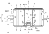
- FIG. 2 is a cross-sectional view showing the gas generator according to the first embodiment in a state before activation.
- FIG. 3 is a partial enlarged view of a gas generator according to a first modification of the first embodiment.
- FIG. 4 is a cross-sectional view showing a state before activation of an airbag module assembly including a gas generator according to a second modification of the first embodiment.
- FIG. 5 is a cross-sectional view showing a state before activation of a gas generator according to a second modification of the first embodiment.
- FIG. 6 is a cross-sectional view showing a state before activation of an airbag module assembly including a gas generator according to the second embodiment.
- FIG. 7 is a cross-sectional view showing a state before activation of the gas generator according to the second embodiment.
- FIG. 1 is a cross-sectional view showing a state before activation of an airbag module assembly 1000 including a gas generator for an airbag (hereinafter, simply referred to as a gas generator) 100 according to the first embodiment.
- FIG. 2 is a cross-sectional view showing a state before activation of the gas generator 100 according to the first embodiment.
- a cross section along a central axis A1 of a housing indicated by reference numeral 1 is shown.
- a direction along the central axis A1 of the housing 1 (axial direction) is defined as a vertical direction of the gas generator 100, an upper shell side indicated by reference numeral 2 in FIG. 2 (i.e., the upper side in FIG.
- the airbag module assembly 1000 includes a gas generator 100, an airbag 200, and a module case 300 that houses them.
- the airbag module assembly 1000 is, for example, an airbag device for protecting a frontal collision (a so-called front airbag device) that is mounted on a vehicle and protects an occupant from impact by inflating and deploying an airbag 200 at the time of a frontal collision of the vehicle.
- the airbag module assembly according to the present disclosure is not limited to a front airbag device.
- the airbag module assembly may be, for example, an airbag device for protecting a side collision (a so-called side airbag device) that protects an occupant from impact by inflating and deploying an airbag at the time of a side collision of the vehicle.
- the airbag module assembly 1000 according to the present embodiment is, for example, installed in the driver's seat (specifically, the steering wheel) of a vehicle, but the airbag module assembly according to the present disclosure may be installed, for example, on the dashboard of the passenger seat or other locations.
- the gas generator 100 is a source of gas for inflating the airbag 200.
- the gas generator 100 is configured to be activated and release gas to the outside when, for example, a sensor (not shown) of the vehicle detects an impact.
- the gas generator 100 will be described in detail later.
- the airbag 200 is a bag that is inflated by the supply of gas from the gas generator 100.
- the airbag 200 is made of, for example, polyamide, and as shown in FIG. 1, is housed in a module case 300 in a folded state before the gas generator 100 is activated.
- the module case 300 is a box that houses the gas generator 100 and the airbag 200.
- the module case 300 includes an airbag cover 400 and a back plate 500.
- the airbag cover 400 includes a cylindrical tube wall portion 401 that forms the side of the module case 300, and a front portion 402 that closes one end of the tube wall portion 401 and forms the front of the module case 300.
- the airbag cover 400 is formed so that it can be combined with, for example, a steering wheel of a vehicle.
- the back plate 500 includes a cylindrical tube wall portion 501 that is fixed to the tube wall portion 401 of the airbag cover 400 to form the side of the module case 300 together with the tube wall portion 401, and a back portion 502 that closes one end of the tube wall portion 501 and forms the back of the module case 300.
- the back portion 502 has an attachment hole 502a for attaching the gas generator 100.
- the airbag 200 is connected to the gas generator 100 and is disposed in a folded state between the gas generator 100 and the front part 402 of the module case 300.
- the airbag module assembly 1000 is installed in the vehicle so that the front portion 402 of the airbag cover 400 faces the occupant (the driver in this example) who is the object of protection of the airbag 200.
- the front portion 402 is ruptured by the pressure caused by the expansion of the airbag 200, and the airbag 200 jumps out of the module case 300 and deploys in front of the occupant. This protects the occupant from impact.
- the gas generator 100 As shown in FIG. 2, the gas generator 100 according to the first embodiment is formed in a short cylindrical shape (disc shape) and includes an ignition device 4, an inner cylinder member 5, a filter 6, a first gas generating agent 110, a second gas generating agent 120, a metal housing 1 that accommodates these, and a temperature rise suppression member 7 provided on the outer surface of the housing 1.
- the gas generator 100 is configured as a so-called single-type gas generator that includes only one ignition device.
- the gas generator 100 is also configured as a so-called pyrotype gas generator that uses only a gas generating agent as a gas source.
- the gas generator according to the present disclosure is not limited to the above.
- the gas generator according to the present disclosure may include a plurality of ignition devices, or may be configured as a so-called hybrid type gas generator that uses a gas generating agent and pressurized gas as a gas source.
- the gas generator 100 is configured to combust the first gas generating agent 110 and the second gas generating agent 120 by activating the igniter 41 included in the ignition device 4, and to release the combustion gas, which is the combustion product, from the gas exhaust hole 11 formed in the housing 1.
- the gas generator 100 will be described below.
- the housing 1 is formed into a short cylindrical shape with both axial ends closed by joining an upper shell 2 and a lower shell 3, each of which is made of metal and formed into a substantially cylindrical shape with a bottom, with their open ends facing each other.
- the housing 1 is made of metal.
- the metal material forming the housing 1 is not particularly limited, but stainless steel is an example.
- the internal space of the housing 1 forms a combustion chamber 10, in which an ignition device 4, an inner cylinder member 5, a filter 6, a first gas generating agent 110, and a second gas generating agent 120 are arranged.
- the upper shell 2 has a cylindrical upper peripheral wall portion 21 and a top plate portion 22 that closes the upper end of the upper peripheral wall portion 21, forming an internal space.
- the lower end of the upper peripheral wall portion 21 forms an opening of the upper shell 2.
- a flange-shaped joint portion 23 extending radially outward is connected to the lower end of the upper peripheral wall portion 21.
- the lower shell 3 has a cylindrical lower peripheral wall portion 31 and a bottom plate portion 32 that closes the lower end of the lower peripheral wall portion 31 and to which the ignition device 4 is fixed, forming an internal space.
- a mounting hole 32a for mounting the ignition device 4 is formed in the bottom plate portion 32.
- a flange-shaped joint portion 33 extending radially outward is connected to the upper end of the lower peripheral wall portion 31.
- the upper shell 2 and the lower shell 3 can be formed, for example, by pressing stainless steel.
- the joints 23 of the upper shell 2 and the joints 33 of the lower shell 3 are overlapped and joined by laser welding or the like to form a short cylindrical housing 1 with both axial ends closed.
- the upper peripheral wall 21 of the upper shell 2 and the lower peripheral wall 31 of the lower shell 3 form a cylindrical peripheral wall 12 that connects the top plate 22 and the bottom plate 32.
- the housing 1 is configured to include the cylindrical peripheral wall 12, the top plate 22 that closes one end of the peripheral wall 12, and the bottom plate 32 that closes the other end of the peripheral wall 12 and has the ignition device 4 attached thereto.
- the top plate 22, the bottom plate 32, and the peripheral wall 12 define the combustion chamber 10.
- the central axis of the peripheral wall 12 defines the central axis A1 of the housing 1.
- the top plate portion 22 is an example of a "first closing portion” according to the present disclosure.
- the bottom plate portion 32 is an example of a "second closing portion” according to the present disclosure.
- the peripheral wall portion 12 (more specifically, the upper peripheral wall portion 21 of the upper shell 2) has multiple gas exhaust holes 11 arranged in a line along the circumferential direction, which connect the combustion chamber 10 to the external space of the housing 1. Before the ignition device 4 is activated, the gas exhaust holes 11 are blocked by sealing tape (not shown).
- the outer surface of the housing 1, specifically, the surface opposite to the surface that defines the internal space (combustion chamber 10) of the housing 1, is indicated by the symbol S1.
- the outer surface S1 is the surface that faces the outside of the gas generator 100.
- the surface of the peripheral wall portion 12 is referred to as the outer surface S12
- the surface of the top plate portion 22 is referred to as the outer surface S22
- the surface of the bottom plate portion 32 is referred to as the outer surface S32.
- the gas generator 100 is attached to the back plate 500 by fixing the flange portion (joints 23, 33) of the housing 1 to the back portion 502 with the gas exhaust hole 11 and top plate portion 22 of the housing 1 inserted into the interior of the module case 300 through the mounting hole 502a of the module case 300.
- the gas exhaust hole 11 and top plate portion 22 of the housing 1 are located inside the module case 300, and the bottom plate portion 32 is located outside the module case 300.
- the gas generator 100 is positioned so that the top plate portion 22 of the housing 1 faces the airbag 200.
- the distance between the gas exhaust hole 11 and the top plate portion 22 in the axial direction of the housing 1 is d1
- the distance between the gas exhaust hole 11 and the bottom plate portion 32 in the axial direction of the housing 1 is d2.
- the gas exhaust hole 11 is formed in a position in the axial direction of the housing 1 such that d1 is shorter than d2. That is, the gas generator 100 according to this embodiment is configured so that d1 ⁇ d2. Therefore, the gas exhaust hole 11 is formed in a position closer to the top plate portion 22 than the bottom plate portion 32.
- the gas exhaust hole 11 is formed in a position closer to the top plate portion 22, which is the side of the top plate portion 22 and the bottom plate portion 32 on which the airbag 200 is arranged, to make it easier to supply gas to the airbag 200.
- the ignition device 4 includes an igniter 41, a collar 42, and a resin part 43, and is attached to the bottom plate part 32 of the lower shell 3.
- the igniter 41 has a metal cup body 411 in which an ignition charge is accommodated, and a pair of current-carrying pins 412, 412 for receiving a current supply from the outside.
- the igniter 41 is activated by an ignition current supplied to the pair of current-carrying pins 412, 412 to combust the ignition charge and release the combustion product to the outside of the cup body 411.
- the collar 42 is formed in a cylindrical shape, and is fixed by welding or the like in a state in which the collar 42 is pressed into a mounting hole 32a formed in the bottom plate part 32.
- the resin part 43 is a resin member that is interposed between the igniter 41 and the collar 42 to fix the igniter 41 to the collar 42.
- the resin part 43 covers the lower part of the igniter 41 and engages with the collar 42, thereby fixing the igniter 41 to the collar 42 such that at least a part of the cup body 411 is exposed from the resin part 43.
- the entire cup body 411 may be overmolded by the resin part 43. That is, the entire cup body 411 may be covered with resin.
- the resin part 43 also forms a connector insertion space inside the collar 42 into which a connector (not shown) that supplies power from an external power source to the pair of energizing pins 412, 412 can be inserted.
- the resin part 43 covers and holds a part of the pair of energizing pins 412, 412 such that the lower ends of the pair of energizing pins 412, 412 are exposed to the connector insertion space.
- the resin part 43 maintains insulation between the pair of energizing pins 412, 412.
- the fixing of the igniter 41 to the collar 42 and the relationship between the collar 42 and the bottom plate portion 32 are not limited to those shown in FIG. 2, and known techniques can be used.
- the inner cylinder member 5 is a cylindrical metal member extending from the bottom plate portion 32 toward the top plate portion 22 so as to surround the ignition device 4.
- the inner cylinder member 5 is formed in a cylindrical shape with both ends open.
- a transfer chamber 51 is formed between the inner cylinder member 5 and the ignition device 4, which is a space in which the first gas generating agent 110 is accommodated.
- the first gas generating agent 110 is burned by the activation of the igniter 41 to generate combustion gas and the like.
- the inner cylinder member 5 is formed with a plurality of communication holes 52 that communicate the internal space (i.e., the transfer chamber 51) with the external space.
- the communication holes 52 are closed by a sealing tape (not shown) before the ignition device 4 is activated.
- the filter 6 is a cylindrical member formed of a metal material, extending in the vertical direction, and has a plurality of holes. As shown in Fig. 2, the filter 6 is disposed in the combustion chamber 10 so as to surround the second gas generating agent 120 and so as to position the gas discharge hole 11 on the outer side of the filter 6 in the radial direction. In other words, the filter 6 is disposed between the second gas generating agent 120 and the gas discharge hole 11 so as to surround the second gas generating agent 120.
- the filter 6 has two axial end faces, one of which (an upper end face indicated by reference numeral 61) is supported by abutting against the top plate portion 22 of the upper shell 2, and the other end face (a lower end face indicated by reference numeral 62) is supported by abutting against the bottom plate portion 32 of the lower shell 3.
- the filter 6 Since the filter 6 has multiple holes, the combustion gas of the second gas generating agent 120 arranged in the combustion chamber 10 can pass through the filter 6.
- the filter 6 functions as a coolant, and as the combustion gas passes through the filter 6, it removes heat from the combustion gas to cool the combustion gas.
- the filter 6 also has the function of filtering the combustion gas by collecting combustion residues contained in the combustion gas.
- the first gas generating agent 110 is a so-called transfer charge that ignites the second gas generating agent by burning when the ignition device 4 is activated.
- a gas generating agent having good ignition properties and a higher combustion temperature than the second gas generating agent 120 can be used.
- the combustion temperature of the first gas generating agent 110 can be set in the range of 1700 to 3000°C.
- a known agent containing nitroguanidine (34% by weight) or strontium nitrate (56% by weight) can be used.
- the first gas generating agent 110 can be in various shapes, such as granular, pellet, cylindrical, and disk shapes.
- a gas generating agent with a relatively low combustion temperature can be used for the second gas generating agent 120.
- the combustion temperature of the second gas generating agent 120 can be set in the range of 1000 to 1700°C.
- a second gas generating agent 120 for example, a known agent containing guanidine nitrate (41% by weight), basic copper nitrate (49% by weight), binders and additives can be used.
- the second gas generating agent 120 can be in various shapes, such as granular, pellet, cylindrical, disk, etc.
- the temperature rise suppression member 7 is a member that absorbs heat from the housing 1 when the temperature of the housing 1 rises due to the combustion of the gas generating agent, thereby suppressing a further rise in temperature of the housing 1. As shown in FIG. 2, the temperature rise suppression member 7 is provided so as to cover a part of the outer surface S1 of the housing 1. In this embodiment, the temperature rise suppression member 7 is provided in contact with only the outer surface S22 of the top plate portion 22 that faces the airbag 200 in the airbag module assembly 1000, among the outer surface S1. The outer surface S22 of the top plate portion 22 is covered with the film-like temperature rise suppression member 7.
- the temperature rise suppression member 7 is in contact with the outer surface S1 of the housing 1 (the outer surface S22 in this example) so that the heat of the housing 1 is easily transferred to the temperature rise suppression member 7. In the entire region of the top plate portion 22, which is the portion of the housing 1 where the temperature rise suppression member 7 is arranged, the temperature rise suppression member 7 is in close contact with the outer surface S22. When the temperature of the housing 1 rises due to the combustion of the gas generating agent, the heat of the housing 1 is transferred by thermal conduction to the temperature rise suppression member 7. Note that the technology according to the present disclosure does not limit the location of the temperature rise suppression member on the housing. It is sufficient that the temperature rise suppression member is provided in contact with the outer surface of the housing so as to cover at least a portion of the outer surface of the housing. For example, the temperature rise suppression member may be provided in contact with the entire area of the outer surface of the housing.
- the temperature rise suppression member 7 contains a heat absorbing agent that exhibits a heat absorbing effect, and a binder agent that coexists with the heat absorbing agent to give flexibility to the temperature rise suppression member 7, and is preferably formed by mixing these.
- the predetermined temperature is set to a temperature higher than the temperature of the housing 1 before the gas generator 100 is activated and lower than the maximum temperature of the housing 1 that is assumed when the gas generating agent is burned when the temperature rise suppression member 7 is not provided on the housing 1.
- the predetermined temperature is not particularly limited, but for example, if the maximum temperature when the temperature of the housing 1 rises due to the combustion of the gas generating agent in a state in which the temperature rise suppression member 7 is not provided is 300°C, the predetermined temperature is set to less than 300°C.
- the heat-absorbing agent suppresses the temperature of the housing 1 from rising to the above-mentioned maximum temperature by causing a chemical change or state change accompanied by an endothermic effect at a temperature lower than the maximum temperature of the housing 1 that is assumed when the gas generating agent is burned when the temperature rise suppression member 7 is not provided on the housing 1.
- the chemical change caused by the heat of the housing 1 here refers to a change to a different compound.
- the change in state caused by the heat of the housing 1 in the heat-absorbing agent refers to a physical change in form.
- the heat-absorbing agent may absorb the heat of the housing 1 by thermally decomposing due to the heat of the housing 1, or may absorb the heat of the housing 1 by sublimating from a solid to a gas due to the heat of the housing 1.
- the heat-absorbing agent cools the housing 1 by removing the thermal energy required for these state changes or chemical changes from the housing 1.
- the heat absorbing agent may be non-combustible.
- the heat absorbing agent may be composed of at least one compound selected from the group consisting of fatty acid polycarbonate and magnesium carbonate, which is a compound that decomposes at a temperature lower than 300°C.
- the heat absorbing agent may be composed of at least one substance that exhibits endothermic properties by sublimation, which is a substance selected from the group consisting of p-dichlorobenzene, DL-camphor, naphthalene, fumaric acid, and terephthalic acid.
- the heat absorbing agent may include a combination of the above compounds.
- the materials of the heat absorbing agent according to the present disclosure are not limited to those mentioned above.
- the binder is used in combination with the heat absorbing agent to provide flexibility to the temperature rise suppression member 7.
- the binder may be present together with the heat absorbing agent in the temperature rise suppression member 7, and the arrangement of the binder is not particularly important, but it is preferable that the binder is mixed with the heat absorbing agent.
- the binder provides flexibility to the temperature rise suppression member 7, which improves the adhesion of the temperature rise suppression member 7 to the housing 1 and makes the temperature rise suppression member 7 less likely to peel off from the housing 1. In this sense, the heat absorbing agent and the binder do not need to be mixed together in the temperature rise suppression member 7.
- the binder may be arranged separately from the heat absorbing agent without being mixed, and may be interposed in a layer between the housing and the heat absorbing agent.
- the binder is mixed with the heat absorbing agent and the two are integrated.
- the temperature rise suppression member 7 attached to the housing 1 is prevented from being damaged (cracks, etc.) due to deformation of the housing 1 or external impact.
- the binder is preferably composed of a compound having, for example, a hydroxyl group or a carbonyl group as a functional group in the molecule, and is more preferably used by mixing it with a heat absorbing agent. Furthermore, by using a compound having a composition including these functional groups as the binder, the flexibility of the temperature rise suppression member 7 is suitably improved. Furthermore, even if gas is generated from the binder heated by heat transfer from the housing 1, for example, the gas can be rendered harmless.
- the binder may be, for example, composed of at least one selected from the group consisting of butadiene rubber, silicone rubber, polyvinyl alcohol, ethylene vinyl alcohol, styrene butadiene rubber, natural rubber, chloroprene rubber, isoprene rubber, acrylic rubber, alkyl acetalized polyvinyl alcohol, and polycarboxylic acid copolymer.
- the binder may include a combination of the above compounds.
- the temperature rise suppression member 7 applied to the housing 1 is less likely to crack even when bent, and the temperature rise suppression member 7 is less likely to peel off from the housing 1.
- the materials of the binder according to the present disclosure are not limited to those mentioned above.
- the content ratio of the heat absorbing agent in the temperature rise suppression member 7 is 70% or more and 95% or less, and the content ratio of the binder agent is 5% or more and 30% or less.
- the ratio of the heat absorbing agent to the binder agent can be selected from the range of 7:3 to 95:5.
- the content ratio of the heat absorbing agent and the content ratio of the binder agent in the temperature rise suppression member according to the present disclosure are not limited to the above range.
- the temperature rise suppression member may be configured to include materials other than the above-mentioned heat absorbing agent and binder agent.
- the temperature rise suppression member 7 can be applied to the outer surface S1 of the housing 1 as a coating by dissolving it in a solvent, applying it to the outer surface S1 of the housing 1, and then drying it.
- the combustion gas of the first gas generating agent 110 breaks the seal tape that has been blocking the communication hole 52 and is discharged from the communication hole 52 to the outside of the transfer chamber 51. Then, the combustion gas of the first gas generating agent 110 comes into contact with the second gas generating agent 120, and the second gas generating agent 120 is ignited. The second gas generating agent 120 burns, generating high-temperature and high-pressure combustion gas in the combustion chamber 10. This combustion gas passes through the filter 6, whereby the combustion gas is cooled and combustion residue is collected. The combustion gas of the second gas generating agent 120, cooled and filtered by the filter 6, passes through the gap 13, breaks the seal tape blocking the gas discharge hole 11, and is discharged from the gas discharge hole 11 to the outside of the gas generator 100.
- the combustion gas of the second gas generating agent 120 flows into the airbag 200 in the module case 300.
- the airbag 200 is inflated by the supply of gas, the front part 402 of the module case 300 is ruptured by the inflation pressure, and the airbag 200 flies out of the module case 300 and deploys in front of the occupant. This forms a cushion between the occupant and the hard structure, protecting the occupant from impact.
- the gas generator 100 is disposed so that the top plate 22 faces the airbag 200 in a folded state. Therefore, the airbag 200, which is deflated after deployment, is likely to come into contact with the top plate 22 of the housing 1. If the top plate 22 of the housing 1 becomes excessively hot after the gas generator 100 is activated, the airbag 200, which is deflated after deployment, comes into contact with the top plate 22 of the housing 1, causing the airbag 200 to melt and potentially generating undesirable gas or odor. Also, as shown in FIG. 2, in the gas generator 100 according to this embodiment, the upper end surface 61 of the metal filter 6, to which high-temperature combustion residue adheres, abuts against the top plate 22 of the housing 1.
- the upper end of the metal inner tube member 5, which is filled with the first gas generating agent 110 abuts against the top plate 22 of the housing 1. Therefore, a large amount of heat is conducted to the top plate portion 22 through the filter 6 and the inner cylinder member 5.
- most of the heat is combustion residue generated from the first gas generating agent 110 and the second gas generating agent 120, which adheres to the inner surface of the housing 1 and the filter 6, causing the temperature of the housing 1 to rise.
- the temperature of the housing 1 gradually rises after the gas generator 100 is activated, so the temperature of the housing 1 rises to its maximum after the airbag 200 exerts its function (after the airbag 200 contracts).
- the top plate portion 22 is likely to become hot, and if the deployed bag comes into contact with it in this state, the bag will melt, leading to the generation of odors and undesirable gases.
- the temperature rise suppression member 7 is provided in contact with the outer surface S22 of the top plate portion 22 of the housing 1. Therefore, as described above, the temperature rise of the housing 1 is suppressed at the top plate portion 22, which is the contact portion with the temperature rise suppression member 7. This prevents the top plate portion 22 facing the airbag 200 in the airbag module assembly 1000 from becoming excessively hot. As a result, the airbag 200 is prevented from melting due to the airbag 200 contracting after deployment coming into contact with the top plate portion 22 of the housing 1. This prevents the generation of odors and undesirable gases. In addition, by suppressing the melting of the airbag 200 after the gas generator 100 is activated, the airbag 200 is prevented from adhering to the housing 1 of the gas generator 100. As a result, the gas generator 100 after activation can be easily disposed of. Furthermore, according to the gas generator 100, the temperature rise of the housing 1 is suppressed, so that the occupant is prevented from being burned when he or she comes into contact with the housing 1.
- the airbag 200 will melt at about 350°C.
- the gas generator 100 can prevent the airbag 200 from melting by using the temperature rise suppression member 7 to suppress the temperature of the housing 1 after the gas generator 100 is activated to, for example, 250°C or less.
- the temperature rise suppression member 7 is prevented from peeling off due to vibrations received during driving of the vehicle or transportation of the gas generator 100, and from peeling off due to the temperature difference of the housing 1 before and after the operation of the gas generator 100. Furthermore, even if the housing 1 is deformed by the pressure of the combustion gas, the temperature rise suppression member 7 deforms in accordance with the deformation of the housing 1 due to its flexibility, so that the temperature rise suppression member 7 is prevented from being damaged.
- the temperature rise suppression member 7 is also prevented from being damaged by external impact. As a result, the temperature rise of the housing 1 after the operation of the gas generator 100 can be efficiently suppressed. Furthermore, by improving the adhesion performance of the temperature rise suppression member 7 to the housing 1, the temperature rise suppression member 7 can be reduced in size. As a result, the gas generator 100 can be made more space-saving.
- the temperature rise suppression member 7 can be formed by separating the binder agent and the heat absorbing agent into layers, and can be arranged so that the binder agent side is in contact with the housing 1, or a layer of binder agent is formed on top of that (on top of the heat absorbing agent). However, in order to give uniform flexibility throughout the temperature rise suppression member 7, it is preferable to arrange the heat absorbing agent and binder agent in a mixed state on the outer surface S22 of the top plate portion 22 of the housing 1.
- the gas generator 100 includes the gas generating agents 110, 120 that generate gas by combustion, the metal housing 1 that accommodates the gas generating agent therein, and the ignition device 4 that ignites the gas generating agent by being activated.
- the housing 1 is formed with a gas exhaust hole 11 that exhausts gas generated by combustion of the gas generating agent to the outside.
- the gas generator 100 further includes a temperature rise suppression member 7 that is provided in contact with the outer surface S1 of the housing 1 so as to cover at least a part of the outer surface S1 (the outer surface S22 in this example).
- This temperature rise suppression member 7 is configured to include a heat absorbing agent and a binder agent.
- the heat absorbing agent absorbs the heat of the housing 1 by undergoing a chemical change or state change due to the heat of the housing 1.
- the binder agent coexists with the heat absorbing agent so that the temperature rise suppression member 7 has flexibility, and is preferably mixed with the heat absorbing agent and used in a state integrated with the heat absorbing agent.
- the heat absorbing agent contained in the temperature rise suppression member 7 actively absorbs thermal energy from the housing 1 due to a state change or chemical change, and the temperature rise of the housing 1 after the gas generator 100 is activated can be suitably suppressed.
- the temperature rise suppression member 7 is given flexibility by the binder agent, so that the temperature rise suppression member 7 can be attached to the housing 1 with good adhesion. As a result, the temperature rise suppression member 7 is prevented from peeling off from the housing 1 for a long period of time, and the temperature rise of the housing 1 can be more efficiently suppressed.
- the thermal effect on the parts (in this example, the airbag 200) arranged around the housing 1 can be reduced after the gas generator 100 is activated. This is suitable when parts (resin parts) that are easily affected by heat are arranged around the housing 1.
- the housing 1 has a cylindrical peripheral wall portion 12 in which the gas discharge hole 11 is formed, a top plate portion 22 that closes one end of the peripheral wall portion 12, and a bottom plate portion 32 that closes the other end of the peripheral wall portion 12, and the gas discharge hole 11 is formed at a position such that the distance d1 between the gas discharge hole 11 and the top plate portion 22 in the axial direction of the housing 1 is shorter than the distance between the gas discharge hole 11 and the bottom plate portion 32.
- the temperature rise suppression member 7 is provided on the outer surface S22 of the top plate portion 22 of the housing 1, which is closer to the gas discharge hole 11 than the bottom plate portion 32.
- the airbag module assembly 1000 includes a gas generator 100 and an airbag 200 that is arranged in a folded state and inflates and deploys due to gas discharged from the gas discharge hole 11, and the gas generator 100 is arranged so that the top plate portion 22 of the housing 1 and the airbag 200 in the folded state face each other. Therefore, the gas generator 100 according to this embodiment can reduce the thermal effect on the airbag 200, which is a component that is arranged to face the top plate portion 22 of the housing 1.
- the technology disclosed herein does not limit the location of the temperature rise suppression member on the housing, but it is preferable to provide the temperature rise suppression member in a location where heat caused by the combustion of the gas generating agent is easily transferred, or in a location close to a component that should be avoided from being thermally affected, if such a component is located nearby.
- FIG. 3 is a partial enlarged view of gas generator 100A according to Modification 1 of the embodiment 1.
- Fig. 3 illustrates the vicinity of top plate portion 22, which is a portion of housing 1A according to Modification 1 where temperature rise suppression member 7 is provided.
- gas generator 100A according to Modification 1 differs from gas generator 100 described above in that, of outer surface S1 of housing 1A, outer surface S22, which is a portion in contact with temperature rise suppression member 7, is formed in an uneven shape. This uneven shape is formed, for example, by roughening the surface of housing 1. With respect to outer surface S1 of housing 1A, the entire outer surface S22 may be uneven, or a portion of outer surface S22 may be uneven.
- the outer surface S22 of the outer surface S1 of the housing 1A which is the contact area with the temperature rise suppression member 7, is formed unevenly, thereby making it possible to increase the contact area between the temperature rise suppression member 7 and the outer surface S22, compared to when the outer surface S22 is a flat surface.
- This improves the efficiency of heat transfer from the housing 1 to the temperature rise suppression member 7.
- heat absorption by the temperature rise suppression member 7 is promoted, making it possible to more efficiently suppress the temperature rise of the housing 1.
- FIG. 4 is a cross-sectional view showing a state before activation of an airbag module assembly 1000B including a gas generator 100B according to Modification 2 of Embodiment 1.
- Fig. 5 is a cross-sectional view showing a state before activation of a gas generator 100B according to Modification 2 of Embodiment 1.
- a cross section along a central axis A1 of a housing 1 is shown.
- the inner cylinder member 5B of the second modification is formed as a bottomed cylinder with one end (upper end) closed and the other end (lower end) open, and is attached to the bottom plate portion 32 by welding the collar 42 of the ignition device 4 to the lower end.
- the temperature rise suppression member 7 is provided in contact only with the outer surface S32 of the bottom plate portion 32 of the housing 1.
- the gas generator 100B according to the second modification also includes a label sheet 8.
- the label sheet 8 is a sheet-like member on which predetermined information is displayed, and is attached to the temperature rise suppression member 7 such that the temperature rise suppression member 7 is interposed between the label sheet 8 and the housing 1.
- the label sheet 8 is attached to the temperature rise suppression member 7 with one of its two surfaces (attachment surface 8a) facing and in contact with the temperature rise suppression member 7.
- the other surface (display surface 8b) of the label sheet 8 displays predetermined information.
- Predetermined information for example, information about the gas generator 100B
- Information about the gas generator 100B may include, for example, handling precautions, manufacturer information, model number, and barcode for management.
- the information displayed on the label sheet according to the present disclosure is not limited to the above.
- the material of the label sheet 8 is not particularly limited, but a heat-resistant resin material such as polyester film can be used.
- the label sheet 8 can be attached to the bottom plate portion 32, for example, by utilizing the adhesiveness of the temperature rise suppression member 7. That is, the temperature rise suppression member 7 can be interposed between the housing 1 and the label sheet 8 as an adhesive (adhesive layer). Note that adhesive may be separately applied to the mounting surface 8a, and the label sheet 8 may be attached to the temperature rise suppression member 7.
- the method of displaying the specified information on the display surface 8b of the label sheet 8 is not particularly limited, but the specified information can be written on the display surface 8b by printing or engraving, for example.
- the bottom plate portion 32 of the housing 1 is exposed to the outside of the module case 300.
- the label sheet 8 is attached to the outer surface S32 of the bottom plate portion 32 of the housing 1 via the temperature rise suppression member 7 so that the label sheet 8 can be seen from outside the module when assembled into the airbag module assembly 1000B.
- the position where the label sheet 8 is attached is not limited to the bottom plate portion 32.
- the temperature rise suppression member 7 between the label sheet 8 and the bottom plate portion 32 of the housing 1, it is possible to suppress the temperature rise of the bottom plate portion 32 after the gas generator 100B is activated.
- the temperature rise of the bottom plate portion 32 to which the label sheet 8 is attached is suppressed via the temperature rise suppression member 7, so that the temperature rise of the label sheet 8 after the gas generator 100B is activated can also be suppressed.
- This makes it possible to prevent, for example, the label sheet 8 from discoloring, denaturing, burning, etc. due to high temperatures after the gas generator 100B is activated, thereby preventing a decrease in the visibility of the display content of the label sheet 8. In other words, the thermal effect on the label sheet 8 can be reduced after the gas generator 100B is activated.
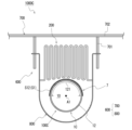
- Figure 6 is a cross-sectional view showing the state before activation of an airbag module assembly 1000C including a gas generator 100C according to embodiment 1.
- a cross section perpendicular to the central axis A1 of the housing 1C is shown.
- the inner cylinder member 5C, filter 6, gas generating agent, etc. of the gas generator 100C are omitted.
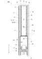
- Figure 7 is a cross-sectional view showing the state before activation of an airbag gas generator 100C according to embodiment 1.
- a cross section along the central axis A1 of the housing 1C is shown.
- the airbag module assembly 1000C includes a gas generator 100C, an airbag 200, and a module case 600 that houses them.
- the airbag module assembly 1000C is a front airbag device that is installed in the passenger seat of a vehicle (more specifically, on the dashboard of the passenger seat).
- the airbag module assembly 1000C may also be applied to a front airbag device for the driver's seat, or to a side airbag device.
- the module case 600 is a box that houses the gas generator 100C and the airbag 200.
- the module case 600 includes an airbag cover 700 and a retainer 800.
- the airbag cover 700 includes a rectangular frame-shaped side wall portion 701 that forms the side surface of the module case 600, and a front portion 702 that closes one end of the side wall portion 701 and forms the front surface of the module case 600.
- the airbag cover 700 is installed so that the front portion 702 forms, for example, a part of the dashboard of a vehicle.
- the retainer 800 is fixed to a vehicle structure (not shown), and is engaged with the side wall portion 701 of the airbag cover 700 to form a storage space for the gas generator 100C and the airbag 200 together with the airbag cover 700.
- the gas generator 100C is arranged in the module case 600 so that the peripheral wall portion 12 of the housing 1C faces the front portion 702.
- the airbag 200 in a folded state is disposed between the peripheral wall portion 12 of the gas generator 100 and the front portion 702 of the module case 600.
- the airbag module assembly 1000C is installed in the vehicle so that the front portion 702 of the airbag cover 700 faces the occupant (in this example, the passenger in the front seat) who is to be protected by the airbag 200.
- the gas generator 100C When the gas generator 100C is activated, the front portion 702 is ruptured by the pressure caused by the expansion of the airbag 200, and the airbag 200 jumps out of the module case 600 and deploys in front of the occupant. This protects the occupant from impact.
- the gas generator 100C according to the second embodiment is formed in a long tubular (cylindrical) shape, and includes an ignition device 4, an inner tube member 5C, a filter 6, a first gas generating agent 110, a second gas generating agent 120, a metal housing 1C that contains these, a temperature rise suppression member 7 provided on the outer surface S1 of the housing 1C, and a partition member 9.
- the gas generator 100C according to the present embodiment is configured as a pyrotype gas generator that uses only a gas generating agent as the gas source, but may also be configured as a hybrid type gas generator that uses a gas generating agent and pressurized gas as the gas source.
- the housing 1C according to the second embodiment is formed in a bottomed cylindrical shape with one end (upper end) closed and the other end (lower end) open.
- the housing 1C has a cylindrical peripheral wall portion 12, a top plate portion 14 closing one end (upper end) of the peripheral wall portion 12, and a fixing portion 15 extending radially inward from the other end (lower end) of the peripheral wall portion 12.
- the ignition device 4 is fixed to the lower end of the peripheral wall portion 12 by crimping the fixing portion 15 with the ignition device 4 fitted into the lower end of the peripheral wall portion 12.
- the inner cylinder member 5C is formed in a cylindrical shape with both ends open, and is attached to the housing 1C by fitting (pressing) the collar 42 of the ignition device 4 into the lower end with the upper end abutting the top plate portion 14 of the housing 1C.
- the inner cylinder member 5C has a first outer diameter portion 53 including its upper end portion and a second outer diameter portion 54 including its lower end portion.
- the first outer diameter portion 53 has a smaller outer diameter than the second outer diameter portion 54, and the first outer diameter portion 53 and the second outer diameter portion 54 are connected by a step portion 55 extending in the radial direction.
- the communication hole 52 is formed in the first outer diameter portion 53.
- the filter 6 is supported by abutting the upper end surface 61 against the top plate portion 14, and the lower end surface 62 against the step portion 55.
- the partition member 9 is a member that divides the internal space of the inner cylinder member 5C in the axial direction.
- the partition member 9 divides the internal space of the inner cylinder member 5C into a first combustion chamber 56 surrounded by the second outer diameter portion 54 and a second combustion chamber 57 surrounded by the first outer diameter portion 53.
- a plurality of through holes 91 are formed in the partition member 9, allowing the first combustion chamber 56 and the second combustion chamber 57 to communicate with each other.
- a first gas generating agent 110 is disposed in the first combustion chamber 56, and a second gas generating agent 120 is disposed in the second combustion chamber 57.
- the gas generator 100C is disposed so as to face the airbag 200 with the peripheral wall portion 12 of the housing 1C in a folded state. More specifically, a portion of half the circumference of the peripheral wall portion 12 faces the airbag 200.
- the portion of the peripheral wall portion 12 that faces the airbag 200 in the airbag module assembly 1000C is referred to as the facing portion 121.
- the gas exhaust hole 11 is formed only in the facing portion 121 of the peripheral wall portion 12.
- the present disclosure is not limited to this.
- the gas exhaust hole 11 may be formed around the entire circumference of the peripheral wall portion 12.
- the temperature rise suppression member 7 is provided in contact only with the outer surface S12 of the facing portion 121, which is the portion of the housing 1C facing the airbag 200.
- the temperature rise suppression member 7 is provided so as to cover the entire area of the facing portion 121 except for the gas exhaust hole 11. More specifically, the temperature rise suppression member 7 is in close contact with the outer surface S12 over the entire area of the facing portion 121, which is the portion of the housing 1C where the temperature rise suppression member 7 is disposed.
- the igniter 41 when the igniter 41 is activated, the combustion products of the ignition charge are released into the first combustion chamber 56, and the first gas generating agent 110 contained in the first combustion chamber 56 is burned, generating combustion gas.
- the combustion gas of the first gas generating agent 110 is released into the second combustion chamber 57 through the through hole 91 of the partition member 9. Then, the combustion gas of the first gas generating agent 110 comes into contact with the second gas generating agent 120, and the second gas generating agent 120 is ignited.
- the second gas generating agent 120 burns, high-temperature and high-pressure combustion gas is generated in the second combustion chamber 57.
- This combustion gas passes through the communication hole 52 and the filter 6 to be cooled and filtered, and then passes through the gap 13 and is released from the gas exhaust hole 11 to the outside of the gas generator 100C.
- the combustion gas of the second gas generating agent 120 is discharged to the outside of the gas generator 100C and then flows into the airbag 200 in the module case 600.
- the airbag 200 is inflated by the supply of gas, the front part 702 of the airbag cover 700 is torn open by the inflation pressure, and the airbag 200 is ejected to the outside of the module case 600 and deployed in front of the occupant. This forms a cushion between the occupant and the hard structure, protecting the occupant from impact.
- the gas generator 100C is disposed so that the opposing portion 121 of the peripheral wall portion 12 faces the airbag 200 in the folded state. Therefore, the airbag 200, which is deflated after deployment, is in a state where it is likely to come into contact with the opposing portion 121 of the housing 1C.
- the temperature rise suppression member 7 is provided in contact with the outer surface S12 of the opposing portion 121 of the housing 1C. Therefore, the temperature rise of the housing 1C is suppressed at the opposing portion 121, which is the contact portion with the temperature rise suppression member 7.
- the gas generator 100C according to the second embodiment can reduce the thermal effects on the components arranged around the peripheral wall portion 12 of the housing 1C by providing the temperature rise suppression member 7 on the outer surface S12 of the peripheral wall portion 12.
- the temperature rise suppression member 7 may be provided so as to contact the entire peripheral wall portion 12.
- Gas generator 110 First gas generating agent (an example of a gas generating agent) 120: Second gas generating agent (an example of a gas generating agent) 200: Airbag 1000: Airbag module assembly
Landscapes
- Physics & Mathematics (AREA)
- Fluid Mechanics (AREA)
- Engineering & Computer Science (AREA)
- Mechanical Engineering (AREA)
- Air Bags (AREA)
- Feeding, Discharge, Calcimining, Fusing, And Gas-Generation Devices (AREA)
Abstract
Description
上記課題を解決するために、本開示の一態様に係るガス発生器は、以下の構成を採用した。即ち、本開示に係るガス発生器は、燃焼によりガスを発生させるガス発生剤と、前記ガス発生剤を内部に収容し、前記ガス発生剤の燃焼により発生した前記ガスを外部に排出するガス排出孔が形成された、金属製のハウジングと、作動することで前記ガス発生剤を着火させる点火装置と、前記ハウジングの外表面の少なくとも一部を覆うように該外表面に接触して設けられた温度上昇抑制部材と、を備え、前記温度上昇抑制部材は、前記ガス発生剤の燃焼に起因して前記ハウジングの温度が上昇すると該ハウジングの熱により化学変化または状態変化を起こすことで前記ハウジングの熱を吸熱する吸熱剤と、前記温度上昇抑制部材が柔軟性を有するように前記吸熱剤と併存するバインダ剤と、を含む、ガス発生器である。
上記の態様1において、前記バインダ剤が前記吸熱剤に混合されていてもよい。
上記の態様1又は2において、前記吸熱剤は、脂肪酸ポリカーボネート、炭酸マグネシウム、フマル酸、及びテレフタル酸からなる群から選択される少なくとも一種を含んでもよい。
上記の態様1から3の何れかにおいて、前記バインダ剤は、ヒドロキシル基またはカルボニル基を有する化合物を含んでもよい。
上記の態様1から4の何れかにおいて、前記温度上昇抑制部材における前記吸熱剤の含有比率は、70%以上95%以下であり、前記温度上昇抑制部材における前記バインダ剤の含有比率は5%以上30%以下であってもよい。
上記の態様1から5の何れかにおいて、前記ハウジングは、前記ガス排出孔が形成された筒状の周壁部と、前記周壁部の一端部を閉塞する第1閉塞部と、前記周壁部の他端部を閉塞する第2閉塞部と、を有し、前記ガス排出孔は、前記ハウジングの軸方向において前記ガス排出孔と前記第1閉塞部との距離が前記ガス排出孔と前記第2閉塞部との距離よりも短くなるような位置に形成されており、前記温度上昇抑制部材は、前記第1閉塞部の外表面に設けられてもよい。
上記の態様1から6の何れかにおいて、前記ハウジングは、前記ガス排出孔が形成された筒状の周壁部を有し、前記温度上昇抑制部材は、前記周壁部の外表面に設けられてもよい。
上記の態様1から7の何れかにおいて、前記ハウジングの外表面のうち、前記温度上昇抑制部材との接触部位は、凹凸状に形成されてもよい。
上記の態様1から8の何れかにおいて、所定の情報を表示するラベルシートを更に備え、前記ラベルシートは、当該ラベルシートと前記ハウジングとの間に前記温度上昇抑制部材が介装されるように、前記温度上昇抑制部材に取り付けられてもよい。
また、本開示に係る技術は、ガス発生器を備えるエアバッグモジュール組立体としても特定することができる。即ち、本開示の一態様は、上記の態様6のガス発生器と、折り畳まれた状態で配置され、前記ガス排出孔から排出される前記ガスによって膨張展開するエアバッグと、を備える、エアバッグモジュール組立体であって、前記ガス発生器は、前記第1閉塞部と折り畳まれた状態の前記エアバッグとが対向するように、配置されてもよい。
また、本開示の一態様に係るエアバッグモジュール組立体は、上記の態様7のガス発生器と、折り畳まれた状態で配置され、前記ガス排出孔から排出される前記ガスによって膨張展開するエアバッグと、を備え、前記ガス発生器は、前記周壁部と折り畳まれた状態の前記エアバッグとが対向するように、配置されており、前記温度上昇抑制部材は、前記周壁部のうち前記エアバッグと対向する部位の外表面に設けられてもよい。
図1は、実施形態1に係るエアバッグ用ガス発生器(以下、単にガス発生器)100を備えるエアバッグモジュール組立体1000の作動前の状態を示す断面図である。図2は、実施形態1に係るガス発生器100の作動前の状態を示す断面図である。図1及び図2では、符号1で示すハウジングの中心軸A1に沿う断面が示されている。ここで、ハウジング1の中心軸A1に沿う方向(軸方向)をガス発生器100の上下方向と定義し、図2の符号2で示す上部シェル側(即ち、図2における上側)をガス発生器100の上側とし、図2の符号3で示す下部シェル側(即ち、図2における下側)をガス発生器100の下側とする。なお、本明細書では、ガス発生器が備える点火装置に含まれる点火器が作動することを、便宜上、「点火装置が作動する」、「ガス発生器が作動する」、又は「エアバッグモジュール組立体が作動する」と表現する場合がある。
図1に示すように、エアバッグモジュール組立体1000は、ガス発生器100と、エアバッグ200と、これらを収容するモジュールケース300と、を備える。エアバッグモジュール組立体1000は、例えば、車両に搭載され、車両の正面衝突時にエアバッグ200を膨張展開させることで乗員を衝撃から保護する、正面衝突保護用のエアバッグ装置(所謂フロントエアバッグ装置)である。但し、本開示に係るエアバッグモジュール組立体は、フロントエアバッグ装置に限定されない。エアバッグモジュール組立体は、例えば、車両の側面衝突時にエアバッグを膨張展開させることで乗員を衝撃から保護する、側面衝突保護用のエアバッグ装置(所謂サイドエアバッグ装置)であってもよい。また、本実施形態に係るエアバッグモジュール組立体1000は、一例として車両の運転席(詳細には、ステアリングホイール)に設置されるものであるが、本開示に係るエアバッグモジュール組立体は、例えば助手席のダッシュボードやその他の箇所に設置されるものであってもよい。
図2に示すように、実施形態1に係るガス発生器100は、短尺筒状(ディスク状)に形成されており、点火装置4と、内筒部材5と、フィルタ6と、第1ガス発生剤110と、第2ガス発生剤120と、これらを収容する金属製のハウジング1と、ハウジング1の外表面に設けられた温度上昇抑制部材7と、を備えている。ガス発生器100は、点火装置を1つのみ備えた、所謂シングルタイプのガス発生器として構成されている。また、ガス発生器100は、ガス源としてガス発生剤のみを用いた所謂パイロタイプのガス発生器として構成されている。但し、本開示に係るガス発生器は、上記に限定されない。本開示に係るガス発生器は、複数の点火装置を備えてもよいし、ガス源としてガス発生剤と加圧ガスとを用いた所謂ハイブリットタイプのガス発生器として構成されてもよい。
ハウジング1は、それぞれが有底略円筒状に形成された金属製の上部シェル2及び下部シェル3が互いの開口端同士を向き合わせた状態で接合されることによって、軸方向の両端が閉塞した短尺円筒状に形成されている。ハウジング1は、金属製である。ハウジング1を形成する金属材料は特に限定されないが、例えばステンレス鋼が挙げられる。ハウジング1の内部空間は、燃焼室10を形成しており、燃焼室10には、点火装置4、内筒部材5、フィルタ6、第1ガス発生剤110、及び第2ガス発生剤120が配置される。
図2に示すように、点火装置4は、点火器41とカラー42と樹脂部43とを含み、下部シェル3の底板部32に取り付けられている。点火器41は、点火薬が収容された金属製のカップ体411と、外部から電流の供給を受けるための一対の通電ピン412,412と、を有する。点火器41は、一対の通電ピン412,412に供給される着火電流により作動することで該点火薬を燃焼させ、その燃焼生成物をカップ体411の外部に放出させる。カラー42は、点火器41を支持する金属製部材である。カラー42は、筒状に形成されており、底板部32に形成された取付孔32aに圧入された状態で、溶接等によって固定されている。樹脂部43は、点火器41とカラー42との間に介装されることで、カラー42に対して点火器41を固定する樹脂製の部材である。樹脂部43は、点火器41の下部を覆うと共にカラー42と係合することで、カップ体411の少なくとも一部が樹脂部43から露出した状態となるように、カラー42に対して点火器41を固定する。但し、樹脂部43によってカップ体411の全体がオーバーモールドされていてもよい。即ち、カップ体411の全体が樹脂に覆われた状態であってもよい。また、樹脂部43は、カラー42の内側に、一対の通電ピン412,412に外部電源からの電力を供給するコネクタ(図示せず)を挿入可能なコネクタ挿入空間を形成している。樹脂部43は、一対の通電ピン412,412の下端がコネクタ挿入空間に露出するように、一対の通電ピン412,412の一部を覆い、保持している。樹脂部43によって、一対の通電ピン412,412同士の絶縁性が保たれている。なお、点火器41とカラー42の固定や、カラー42と底板部32の関係は図2に限られることなく、公知の技術を使用できる。
内筒部材5は、点火装置4を取り囲むようにして底板部32から天板部22に向かって延びる筒状の金属製部材である。内筒部材5は、両端が開放した筒状に形成されている。燃焼室10のうち、内筒部材5と点火装置4との間には、第1ガス発生剤110が収容される空間である伝火室51が形成されている。第1ガス発生剤110は、点火器41の作動により燃焼し、燃焼ガス等を発生させる。また、内筒部材5には、その内部空間(即ち、伝火室51)と外部空間とを連通する連通孔52が複数形成されている。連通孔52は、点火装置4が作動する前の状態では、シールテープ(図示なし)により閉塞されている。
フィルタ6は、金属材料により形成され、上下方向に延在する筒状の部材であって、複数の孔を有している。図2に示すように、フィルタ6は、第2ガス発生剤120を取り囲み、且つ、その径方向においてガス排出孔11がその外側に位置するように、燃焼室10に配置されている。つまり、フィルタ6は、第2ガス発生剤120を取り囲むように第2ガス発生剤120とガス排出孔11との間に配置されている。フィルタ6は、軸方向の両端面のうち、一端面(符号61で示す上端面)が上部シェル2の天板部22に当接して支持され、他端面(符号62で示す下端面)が下部シェル3の底板部32に当接して支持されている。
第1ガス発生剤110は、点火装置4の作動により燃焼することで第2ガス発生剤を着火させる、所謂伝火薬である。第1ガス発生剤110としては、公知の黒色火薬の他、着火性が良く、第2ガス発生剤120よりも燃焼温度の高いガス発生剤を使用することができる。第1ガス発生剤110の燃焼温度は、1700~3000℃の範囲に設定することができる。このような第1ガス発生剤110としては、例えば、ニトログアニジン(34重量%)、硝酸ストロンチウム(56重量%)を含む、公知のものを用いることができる。また、第1ガス発生剤110には、例えば顆粒状、ペレット状、円柱状、ディスク状等、種々の形状を採用できる。
温度上昇抑制部材7は、ガス発生剤の燃焼に起因してハウジング1が昇温するとハウジング1の熱を吸熱することで、ハウジング1の更なる昇温を抑制する部材である。図2に示すように、温度上昇抑制部材7は、ハウジング1の外表面S1の一部を覆うように設けられている。本実施形態では、温度上昇抑制部材7は、外表面S1のうち、エアバッグモジュール組立体1000においてエアバッグ200に対向する天板部22の外表面S22のみに接触して設けられている。天板部22の外表面S22は、膜状の温度上昇抑制部材7によって被覆されている。本実施形態に係る温度上昇抑制部材7は、ハウジング1の熱が温度上昇抑制部材7に伝熱し易いように、ハウジング1の外表面S1(本例では外表面S22)に接触している。ハウジング1において温度上昇抑制部材7が配置される部位である天板部22の全領域において、温度上昇抑制部材7が外表面S22に密着している。ガス発生剤の燃焼に起因してハウジング1が昇温すると、熱伝導によってハウジング1の熱が温度上昇抑制部材7へ伝わる。なお、本開示に係る技術は、ハウジングにおいて温度上昇抑制部材が設けられる部位を限定しない。温度上昇抑制部材は、ハウジングの外表面の少なくとも一部を覆うように該外表面に接触して設けられていればよい。例えば、ハウジングの外表面の全領域に接触するように温度上昇抑制部材が設けられてもよい。
以下、実施形態1に係るガス発生器100及びエアバッグモジュール組立体1000の動作について、図1及び図2を参照しながら説明する。車両のセンサ(図示せず)が衝撃を感知すると、一対の通電ピン412,412に着火電流が供給され、点火器41が作動する。すると、点火器41のカップ体411に収容された点火薬が燃焼し、その燃焼生成物である火炎や高温のガス等がカップ体411の外部に放出される。これにより、伝火室51に収容された第1ガス発生剤110が燃焼し、燃焼ガスが発生する。第1ガス発生剤110の燃焼ガスは、連通孔52を閉塞していたシールテープを破って連通孔52から伝火室51の外部へ放出される。すると、第1ガス発生剤110の燃焼ガスが第2ガス発生剤120と接触し、第2ガス発生剤120が着火される。第2ガス発生剤120が燃焼することで、燃焼室10に高温・高圧の燃焼ガスが生成される。この燃焼ガスがフィルタ6を通過することで、燃焼ガスが冷却され、燃焼残渣が捕集される。フィルタ6によって冷却及び濾過された第2ガス発生剤120の燃焼ガスは、間隙13を通り、ガス排出孔11を閉塞していたシールテープを破ってガス排出孔11からガス発生器100の外部へと放出される。第2ガス発生剤120の燃焼ガスは、ガス発生器100の外部へ放出された後に、モジュールケース300内のエアバッグ200内に流入する。ガスの供給によりエアバッグ200が膨張すると、その膨張圧力によりモジュールケース300の正面部402が開裂することで、エアバッグ200がモジュールケース300の外部へ飛び出して乗員の正面で展開する。これにより、乗員と堅い構造物の間にクッションが形成され、乗員が衝撃から保護される。
ガス発生器100が作動すると、ガス発生剤の燃焼による熱は、ハウジング1に伝熱し、ハウジング1に接触している温度上昇抑制部材7へと熱伝導により伝熱する。そのため、ハウジング1の昇温に伴って、温度上昇抑制部材7も昇温する。温度上昇抑制部材7が所定温度まで昇温すると、温度上昇抑制部材7に含まれる吸熱剤が状態変化または化学変化を開始する。このとき、吸熱剤は、ハウジング1から熱エネルギーを奪い、その熱エネルギーを化学変化または状態変化に使用する。その結果、吸熱剤の吸熱作用によってハウジング1が冷却され、ハウジング1の昇温が抑制される。ハウジング1は、温度上昇抑制部材7との接触部位から吸熱されるため、温度上昇抑制部材7と接触している天板部22において昇温が抑制される。
以上のように、実施形態1に係るガス発生器100は、燃焼によりガスを発生させるガス発生剤110,120と、ガス発生剤を内部に収容する金属製のハウジング1と、作動することでガス発生剤を着火させる点火装置4と、を備える。ハウジング1には、ガス発生剤の燃焼により発生したガスを外部に排出するガス排出孔11が形成されている。そして、ガス発生器100は、ハウジング1の外表面S1の少なくとも一部(本例では外表面S22)を覆うように外表面S1に接触して設けられた温度上昇抑制部材7を更に備える。この温度上昇抑制部材7は、吸熱剤とバインダ剤とを含んで構成されている。吸熱剤は、ガス発生剤の燃焼に起因してハウジング1の温度が上昇するとハウジング1の熱により化学変化または状態変化を起こすことでハウジング1の熱を吸熱する。バインダ剤は、温度上昇抑制部材7が柔軟性を有するように吸熱剤と併存しており、好ましくは吸熱剤と混合されることで吸熱剤と一体化した状態で使用される。
以下、実施形態1の変形例に係るガス発生器及びエアバッグモジュール組立体について説明する。変形例の説明では、図1及び図2で説明したガス発生器100との相違点を中心に説明し、ガス発生器100と同様の点については詳細な説明は割愛する。
図3は、実施形態1の変形例1に係るガス発生器100Aの部分拡大図である。図3では、変形例1に係るハウジング1Aのうち温度上昇抑制部材7が設けられている部位である天板部22付近が図示されている。図3に示すように、変形例1に係るガス発生器100Aは、ハウジング1Aの外表面S1のうち、温度上昇抑制部材7との接触部位である外表面S22が凹凸状に形成されている点で、上述のガス発生器100と相違する。この凹凸状は、例えば、ハウジング1の表面を粗面化処理することで形成される。ハウジング1Aの外表面S1は、外表面S22の全体が凹凸状であってもよいし、外表面S22の一部が凹凸状であってもよい。
図4は、実施形態1の変形例2に係るガス発生器100Bを備えるエアバッグモジュール組立体1000Bの作動前の状態を示す断面図である。図5は、実施形態1の変形例2に係るガス発生器100Bの作動前の状態を示す断面図である。図4及び図5では、ハウジング1の中心軸A1に沿う断面が示されている。
以下、実施形態2に係るガス発生器及びエアバッグモジュール組立体について説明する。実施形態2の説明では、図1及び図2で説明した実施形態1に係るガス発生器100との相違点を中心に説明し、ガス発生器100と同様の点については詳細な説明は割愛する。
以上、本開示に係る技術の実施形態について説明したが、本明細書に開示された各々の態様は、本明細書に開示された他のいかなる特徴とも組み合わせることができる。
4・・・・・・点火装置
7・・・・・・温度上昇抑制部材
8・・・・・・ラベルシート
11・・・・・ガス排出孔
12・・・・・周壁部
22・・・・・天板部(第1閉塞部の一例)
32・・・・・底板部(第2閉塞部の一例)
100・・・・ガス発生器
110・・・・第1ガス発生剤(ガス発生剤の一例)
120・・・・第2ガス発生剤(ガス発生剤の一例)
200・・・・エアバッグ
1000・・・エアバッグモジュール組立体
Claims (11)
- 燃焼によりガスを発生させるガス発生剤と、
前記ガス発生剤を内部に収容し、前記ガス発生剤の燃焼により発生した前記ガスを外部に排出するガス排出孔が形成された、金属製のハウジングと、
作動することで前記ガス発生剤を着火させる点火装置と、
前記ハウジングの外表面の少なくとも一部を覆うように該外表面に接触して設けられた温度上昇抑制部材と、
を備え、
前記温度上昇抑制部材は、前記ガス発生剤の燃焼に起因して前記ハウジングの温度が上昇すると該ハウジングの熱により化学変化または状態変化を起こすことで前記ハウジングの熱を吸熱する吸熱剤と、前記温度上昇抑制部材が柔軟性を有するように前記吸熱剤と併存するバインダ剤と、を含む、
ガス発生器。 - 前記バインダ剤が前記吸熱剤に混合されている、
請求項1に記載のガス発生器。 - 前記吸熱剤は、脂肪酸ポリカーボネート、炭酸マグネシウム、フマル酸、及びテレフタル酸からなる群から選択される少なくとも一種を含む、
請求項1又は2に記載のガス発生器。 - 前記バインダ剤は、ヒドロキシル基またはカルボニル基を有する化合物を含む、
請求項1から3の何れか一項に記載のガス発生器。 - 前記温度上昇抑制部材における前記吸熱剤の含有比率は、70%以上95%以下であり、
前記温度上昇抑制部材における前記バインダ剤の含有比率は5%以上30%以下である、
請求項1から4の何れか一項に記載のガス発生器。 - 前記ハウジングは、前記ガス排出孔が形成された筒状の周壁部と、前記周壁部の一端部を閉塞する第1閉塞部と、前記周壁部の他端部を閉塞する第2閉塞部と、を有し、
前記ガス排出孔は、前記ハウジングの軸方向において前記ガス排出孔と前記第1閉塞部との距離が前記ガス排出孔と前記第2閉塞部との距離よりも短くなるような位置に形成されており、
前記温度上昇抑制部材は、前記第1閉塞部の外表面に設けられている、
請求項1から5の何れか一項に記載のガス発生器。 - 前記ハウジングは、前記ガス排出孔が形成された筒状の周壁部を有し、
前記温度上昇抑制部材は、前記周壁部の外表面に設けられている、
請求項1から6の何れか一項に記載のガス発生器。 - 前記ハウジングの外表面のうち、前記温度上昇抑制部材との接触部位は、凹凸状に形成されている、
請求項1から7の何れか一項に記載のガス発生器。 - 所定の情報を表示するラベルシートを更に備え、
前記ラベルシートは、当該ラベルシートと前記ハウジングとの間に前記温度上昇抑制部材が介装されるように、前記温度上昇抑制部材に取り付けられている、
請求項1から8の何れか一項に記載のガス発生器。 - 請求項6に記載のガス発生器と、
折り畳まれた状態で配置され、前記ガス排出孔から排出される前記ガスによって膨張展開するエアバッグと、
を備える、エアバッグモジュール組立体であって、
前記ガス発生器は、前記第1閉塞部と折り畳まれた状態の前記エアバッグとが対向するように、配置されている、
エアバッグモジュール組立体。 - 請求項7に記載のガス発生器と、
折り畳まれた状態で配置され、前記ガス排出孔から排出される前記ガスによって膨張展開するエアバッグと、
を備える、エアバッグモジュール組立体であって、
前記ガス発生器は、前記周壁部と折り畳まれた状態の前記エアバッグとが対向するように、配置されており、
前記温度上昇抑制部材は、前記周壁部のうち前記エアバッグと対向する部位の外表面に設けられている、
エアバッグモジュール組立体。
Priority Applications (3)
| Application Number | Priority Date | Filing Date | Title |
|---|---|---|---|
| DE112023004975.0T DE112023004975T5 (de) | 2023-01-24 | 2023-12-22 | Gasgenerator und Airbag-Modulanordnung |
| CN202380092120.6A CN120569313A (zh) | 2023-01-24 | 2023-12-22 | 气体发生器和气囊模块组件 |
| US19/277,721 US20250346206A1 (en) | 2023-01-24 | 2025-07-23 | Gas generator and airbag module assembly |
Applications Claiming Priority (2)
| Application Number | Priority Date | Filing Date | Title |
|---|---|---|---|
| JP2023-008921 | 2023-01-24 | ||
| JP2023008921A JP2024104609A (ja) | 2023-01-24 | 2023-01-24 | ガス発生器及びエアバッグモジュール組立体 |
Related Child Applications (1)
| Application Number | Title | Priority Date | Filing Date |
|---|---|---|---|
| US19/277,721 Continuation US20250346206A1 (en) | 2023-01-24 | 2025-07-23 | Gas generator and airbag module assembly |
Publications (1)
| Publication Number | Publication Date |
|---|---|
| WO2024157698A1 true WO2024157698A1 (ja) | 2024-08-02 |
Family
ID=91970501
Family Applications (1)
| Application Number | Title | Priority Date | Filing Date |
|---|---|---|---|
| PCT/JP2023/046085 Ceased WO2024157698A1 (ja) | 2023-01-24 | 2023-12-22 | ガス発生器及びエアバッグモジュール組立体 |
Country Status (5)
| Country | Link |
|---|---|
| US (1) | US20250346206A1 (ja) |
| JP (1) | JP2024104609A (ja) |
| CN (1) | CN120569313A (ja) |
| DE (1) | DE112023004975T5 (ja) |
| WO (1) | WO2024157698A1 (ja) |
Citations (3)
| Publication number | Priority date | Publication date | Assignee | Title |
|---|---|---|---|---|
| JPS5166937U (ja) * | 1974-11-20 | 1976-05-27 | ||
| US6314888B1 (en) * | 1998-05-19 | 2001-11-13 | Trw Airbag Systems Gmbh & Co. Kg | Multi-stage gas generator with thermal uncoupling of the propellant charges |
| JP2005112302A (ja) * | 2003-10-10 | 2005-04-28 | Nissan Motor Co Ltd | ガス発生器及びガス発生器の作動状態の識別方法 |
-
2023
- 2023-01-24 JP JP2023008921A patent/JP2024104609A/ja active Pending
- 2023-12-22 CN CN202380092120.6A patent/CN120569313A/zh active Pending
- 2023-12-22 DE DE112023004975.0T patent/DE112023004975T5/de active Pending
- 2023-12-22 WO PCT/JP2023/046085 patent/WO2024157698A1/ja not_active Ceased
-
2025
- 2025-07-23 US US19/277,721 patent/US20250346206A1/en active Pending
Patent Citations (3)
| Publication number | Priority date | Publication date | Assignee | Title |
|---|---|---|---|---|
| JPS5166937U (ja) * | 1974-11-20 | 1976-05-27 | ||
| US6314888B1 (en) * | 1998-05-19 | 2001-11-13 | Trw Airbag Systems Gmbh & Co. Kg | Multi-stage gas generator with thermal uncoupling of the propellant charges |
| JP2005112302A (ja) * | 2003-10-10 | 2005-04-28 | Nissan Motor Co Ltd | ガス発生器及びガス発生器の作動状態の識別方法 |
Also Published As
| Publication number | Publication date |
|---|---|
| US20250346206A1 (en) | 2025-11-13 |
| CN120569313A (zh) | 2025-08-29 |
| JP2024104609A (ja) | 2024-08-05 |
| DE112023004975T5 (de) | 2025-10-23 |
Similar Documents
| Publication | Publication Date | Title |
|---|---|---|
| US5845933A (en) | Airbag inflator with consumable igniter tube | |
| KR100653550B1 (ko) | 에어백용 가스 발생기 및 에어백 장치 | |
| EP2426015B1 (en) | Gas generator | |
| KR100190889B1 (ko) | 팽창식 차량 탑승자 구속 기구 팽창장치 | |
| EP2383154B1 (en) | Gas generator | |
| JPH0813625B2 (ja) | エアーバック膨張装置 | |
| JPH02152510A (ja) | 非溶接拡張装置のフィルタ組立体 | |
| JPH1159314A (ja) | エアバッグ用ガス発生器 | |
| JP2622369B2 (ja) | 着火性ガス発生材料の着火方法及びその着火装置 | |
| JPH11217055A (ja) | ガス発生器 | |
| WO2024157698A1 (ja) | ガス発生器及びエアバッグモジュール組立体 | |
| JPH1159315A (ja) | エアバッグ用ガス発生器のクッション部材 | |
| JP2002370607A (ja) | ガス発生器 | |
| JPH079940A (ja) | エアバッグ展開用ガス発生装置のガス発生剤パック | |
| JP3218213B2 (ja) | エアバッグ用ガス発生器及びエアバッグ装置 | |
| WO2006030967A1 (ja) | ガス発生器 | |
| JP7587443B2 (ja) | 点火器およびガス発生器 | |
| JP3041188U (ja) | 自動点火装置とこれを組込んだエアバッグインフレータ | |
| JP2008213820A (ja) | 自己点火クレードルを有するインフレータ | |
| JP4994787B2 (ja) | ガス発生器 | |
| JPH10297415A (ja) | ガス発生器 | |
| JP2025125503A (ja) | ガス発生器およびガス発生器の製造方法 | |
| JP7478705B2 (ja) | ガス発生器 | |
| JP7434111B2 (ja) | ガス発生器 | |
| JP2025151222A (ja) | ガス発生器 |
Legal Events
| Date | Code | Title | Description |
|---|---|---|---|
| 121 | Ep: the epo has been informed by wipo that ep was designated in this application |
Ref document number: 23918652 Country of ref document: EP Kind code of ref document: A1 |
|
| WWE | Wipo information: entry into national phase |
Ref document number: 202380092120.6 Country of ref document: CN |
|
| WWE | Wipo information: entry into national phase |
Ref document number: 112023004975 Country of ref document: DE |
|
| WWP | Wipo information: published in national office |
Ref document number: 202380092120.6 Country of ref document: CN |
|
| WWP | Wipo information: published in national office |
Ref document number: 112023004975 Country of ref document: DE |
|
| 122 | Ep: pct application non-entry in european phase |
Ref document number: 23918652 Country of ref document: EP Kind code of ref document: A1 |