WO2024219449A1 - Procédé de fabrication de filtre, système de fabrication de filtre et dispositif de pliage - Google Patents
Procédé de fabrication de filtre, système de fabrication de filtre et dispositif de pliage Download PDFInfo
- Publication number
- WO2024219449A1 WO2024219449A1 PCT/JP2024/015383 JP2024015383W WO2024219449A1 WO 2024219449 A1 WO2024219449 A1 WO 2024219449A1 JP 2024015383 W JP2024015383 W JP 2024015383W WO 2024219449 A1 WO2024219449 A1 WO 2024219449A1
- Authority
- WO
- WIPO (PCT)
- Prior art keywords
- filter
- filter paper
- axis direction
- pleated
- manufacturing
- Prior art date
- Legal status (The legal status is an assumption and is not a legal conclusion. Google has not performed a legal analysis and makes no representation as to the accuracy of the status listed.)
- Ceased
Links
Images





















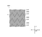
Classifications
-
- B—PERFORMING OPERATIONS; TRANSPORTING
- B01—PHYSICAL OR CHEMICAL PROCESSES OR APPARATUS IN GENERAL
- B01D—SEPARATION
- B01D29/00—Filters with filtering elements stationary during filtration, e.g. pressure or suction filters, not covered by groups B01D24/00 - B01D27/00; Filtering elements therefor
- B01D29/01—Filters with filtering elements stationary during filtration, e.g. pressure or suction filters, not covered by groups B01D24/00 - B01D27/00; Filtering elements therefor with flat filtering elements
- B01D29/05—Filters with filtering elements stationary during filtration, e.g. pressure or suction filters, not covered by groups B01D24/00 - B01D27/00; Filtering elements therefor with flat filtering elements supported
- B01D29/07—Filters with filtering elements stationary during filtration, e.g. pressure or suction filters, not covered by groups B01D24/00 - B01D27/00; Filtering elements therefor with flat filtering elements supported with corrugated, folded or wound filtering sheets
-
- B—PERFORMING OPERATIONS; TRANSPORTING
- B01—PHYSICAL OR CHEMICAL PROCESSES OR APPARATUS IN GENERAL
- B01D—SEPARATION
- B01D39/00—Filtering material for liquid or gaseous fluids
-
- B—PERFORMING OPERATIONS; TRANSPORTING
- B01—PHYSICAL OR CHEMICAL PROCESSES OR APPARATUS IN GENERAL
- B01D—SEPARATION
- B01D46/00—Filters or filtering processes specially modified for separating dispersed particles from gases or vapours
- B01D46/52—Particle separators, e.g. dust precipitators, using filters embodying folded corrugated or wound sheet material
-
- B—PERFORMING OPERATIONS; TRANSPORTING
- B65—CONVEYING; PACKING; STORING; HANDLING THIN OR FILAMENTARY MATERIAL
- B65H—HANDLING THIN OR FILAMENTARY MATERIAL, e.g. SHEETS, WEBS, CABLES
- B65H45/00—Folding thin material
- B65H45/02—Folding limp material without application of pressure to define or form crease lines
- B65H45/06—Folding webs
-
- B—PERFORMING OPERATIONS; TRANSPORTING
- B65—CONVEYING; PACKING; STORING; HANDLING THIN OR FILAMENTARY MATERIAL
- B65H—HANDLING THIN OR FILAMENTARY MATERIAL, e.g. SHEETS, WEBS, CABLES
- B65H45/00—Folding thin material
- B65H45/02—Folding limp material without application of pressure to define or form crease lines
- B65H45/06—Folding webs
- B65H45/10—Folding webs transversely
- B65H45/101—Folding webs transversely in combination with laying, i.e. forming a zig-zag pile
Definitions
- filters for filtering fluids that is, liquids such as air and liquids such as water.
- Such filters are preferable because the larger the area used for filtering the fluid (hereinafter referred to as the "effective area"), the lower the flow rate per unit area, and the smaller the proportion of particles to be removed that pass through the filter.
- the area of the filter is enlarged while it remains flat, the size of the filter will increase in proportion to the enlargement of the effective area of the filter, which is often undesirable depending on the application of the filter.
- filters that are folded in a zigzag pattern to form pleats see, for example, Patent Document 1).
- the objective of this disclosure is to improve the manufacturing efficiency of pleated filters.
- a method for manufacturing a pleated filter comprising the steps of: A folding step of folding the filter paper is included. In the folding process, the filter paper is folded between restricting members that are disposed on both sides of the filter paper and restrict movement of the filter paper in a direction perpendicular to the surface of the filter paper.
- the invention described in claim 2 is a method for manufacturing a filter according to claim 1,
- the restricting member is configured to move in the travelling direction of the filter paper.
- the invention described in claim 4 is a method for producing a filter according to claim 3, comprising the steps of:
- the restricting member is a plurality of belts that move in the direction in which the filter paper travels.
- the invention described in claim 5 is a method for manufacturing a filter according to claim 1,
- the restriction members are arranged so that the intervals between them gradually increase in the direction in which the filter paper travels.
- the invention described in claim 8 is a method for producing a filter according to any one of claims 1 to 7, comprising the steps of: In the folding step, the filter paper is folded by pushing the filter paper from the front with a plate-shaped member.
- the invention described in claim 11 is a method for producing a filter according to any one of claims 1 to 7, comprising the steps of: In the folding step, the filter paper is folded so that the folded filter paper is in a fully compressed state.
- the invention described in claim 13 is a method for producing a filter according to any one of claims 1 to 7, comprising the steps of:
- the method includes a shaking step of shaking the filter paper before the folding step.
- the invention described in claim 14 is a method for producing a filter according to any one of claims 1 to 7, comprising the steps of:
- the method includes a fixing step of adding a fixing material to the filter paper folded in the folding step, the fixing material fixing the filter paper in the folded state.
- the invention described in claim 15 is a method for producing a filter according to claim 14, comprising the steps of:
- the fixing step includes a disposing step of disposing a thermoplastic resin on both sides of the filter paper, and a heating step of heating the thermoplastic resin.
- the invention described in claim 16 is a method for producing a filter according to claim 15, comprising the steps of:
- the thermoplastic resin is in the form of fibers or threads.
- the invention described in claim 17 is a method for producing a filter according to claim 14, comprising the steps of:
- the fixing step includes a sticking step of sticking films to both sides of the filter paper.
- the invention described in claim 18 is a method for producing a filter according to any one of claims 1 to 7, comprising the steps of: The filter paper having the pleats formed and a fixing material added thereto for fixing the folded state is further folded in the folding step.
- the invention described in claim 19 is a method for producing a filter according to claim 18, comprising the steps of:
- the pleats formed in the filter paper have a height of 2 mm or less.
- a filter manufacturing system for manufacturing a pleated filter comprising: A folding means for folding the filter paper is provided, The folding means is disposed on both sides of the filter paper, and folds the filter paper between restricting members that restrict movement of the filter paper in a direction perpendicular to the surface of the filter paper.
- the invention described in claim 21 is a folding device, It has multiple belts arranged opposite each other, with opposing surfaces moving in the same direction.
- This disclosure makes it possible to improve the manufacturing efficiency of pleated filters.
- FIG. 1 is a perspective view of a pleated filter according to a first embodiment.
- FIG. 2 is a perspective view of the filter unit according to the first embodiment.
- FIG. 3 is a cross-sectional view taken along line III-III of FIG. 2 .
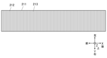
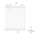
- FIG. 2 is a plan view of the filter paper according to the first embodiment.
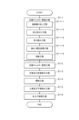
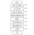
- 4 is a flowchart showing a filter unit manufacturing method according to the first embodiment.
- FIG. 1 is a schematic diagram showing a filter unit manufacturing system according to a first embodiment.
- FIG. 2 is a perspective view of a compression filter according to the first embodiment.
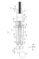
- FIG. 1 is a diagram showing a compressed filter manufacturing device of a filter unit manufacturing system according to a first embodiment.
- FIG. 1 is a plan view showing the state in which the right and left plates are attached to the compression filter in the right and left plate attachment step of the filter unit manufacturing method according to the first embodiment.
- FIG. 13 is a plan view showing a state in which the gap between the right and left plates has been widened in the opening process of the filter unit manufacturing method according to the first embodiment.
- FIG. FIG. 13 is a diagram showing a simplified compressed filter manufacturing apparatus according to a modified example of the first embodiment.
- FIG. 13 is a diagram showing a method for manufacturing a compressed filter using a simplified compressed filter manufacturing apparatus according to a modified example of the first embodiment, showing the state in which filter paper is placed in the compression section.
- FIG. 13 is a diagram showing a method for manufacturing a compressed filter using a simplified compressed filter manufacturing apparatus according to a modified example of the first embodiment, illustrating the state in which compression of filter paper has begun in the compression section.
- FIG. 13 is a diagram showing a method for manufacturing a compressed filter using a simplified compressed filter manufacturing apparatus relating to a modified example of the first embodiment, showing the state in which compression of the filter paper is completed in the compression section.
- FIG. 11 is a side view showing another example of the compression unit of the simplified compressed filter manufacturing apparatus according to the modified example of the first embodiment.
- FIG. 11 is a plan view showing another example of the compression unit of the simplified compressed filter manufacturing apparatus according to the modified example of the first embodiment.
- FIG. 11 is a front view showing another example of the compression unit of the simplified compressed filter manufacturing apparatus according to the modified example of the first embodiment.
- FIG. 2 is a perspective view of a multi-filter unit according to the first embodiment.
- FIG. 4 is a diagram showing a method of a compression test for the compressed filter according to the first embodiment.
- FIG. 2 is a perspective view of a multi-stage inclined compression filter with left and right plates according to the first embodiment.
- FIG. 2 is a perspective view of a multi-stage parallel compression filter with left and right plates according to the first embodiment.
- FIG. 2 is a perspective view of a filter unit manufactured from a multi-stage parallel compression filter with left and right plates according to the first embodiment.
- 2 is a diagram showing a rocking device provided in the filter unit manufacturing system according to the first embodiment.
- FIG. 1 is a diagram showing a state in which a rocking device is provided in the filter unit manufacturing system according to the first embodiment.
- FIG. 1 is a diagram showing how the filter paper is folded in the folding device of the filter unit manufacturing system according to the first embodiment, and shows a case where the thickness of the filter paper is about half the interval between the belts. Note that for convenience of explanation, the interval between the belts is constant. 1 is a diagram showing how the filter paper is folded in the folding device of the filter unit manufacturing system according to the first embodiment, and shows a case in which the thickness of the filter paper is significantly smaller than the interval between the belts. Note that for convenience of explanation, the interval between the belts is constant.
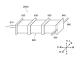
- FIG. 5 is a perspective view of a monoblock filter according to a second embodiment.
- FIG. 11 is a perspective view of a polyblock filter according to a second embodiment.
- FIG. 11 is a perspective view of a filter unit according to a second embodiment.
- 26 is a cross-sectional view taken along the line XXVI-XXVI of FIG. 25.
- FIG. 27 is a cross-sectional view taken along the line XXVII-XXVII in FIG. 25 .
- 10 is a flowchart showing a filter unit manufacturing method according to a second embodiment.
- FIG. 5 is a perspective view of a membrane-attached monoblock filter according to a second embodiment.
- FIG. 11 is a perspective view of a multi-stage parallel compression filter with left and right plates according to a second embodiment. 11 is an enlarged view of a portion near the right end of the front surface of a filter unit according to a second embodiment.
- FIG. 31B is a cross-sectional view taken along the line b-b of FIG. 31A.
- FIG. 11 is a perspective view of a filter unit according to a third embodiment.
- FIG. 33 is a cross-sectional view taken along the line XXXIII-XXXIII of FIG. 32 .
- 33 is a cross-sectional view taken along the line XXXIV-XXXIV of FIG. 32.
- 13 is a flowchart showing a filter unit manufacturing method according to a third embodiment.
- FIG. 13 is a side view showing the compressed filter after the grouping step in the filter unit manufacturing method according to the third embodiment.
- FIG. 13 is a side view showing the compressed filter after a compressed filter alignment step in the filter unit manufacturing method according to the third embodiment.
- FIG. 13 is a side view showing the compressed filter after the right opening frame and left opening frame mounting step in the filter unit manufacturing method according to the third embodiment.
- FIG. FIG. 13 is a diagram showing a compressed filter manufacturing apparatus according to a fourth embodiment.
- 10 is a flowchart showing a method for manufacturing a fine pleated filter according to a fourth embodiment.
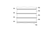
- FIG. 13 is a cross-sectional view parallel to the XZ plane, showing a state of a portion of the fine-pleated filter after pressure is applied in an example of a fixing step in a filter unit manufacturing method according to a fourth embodiment.
- FIG. 13 is a cross-sectional view parallel to the XZ plane showing the state of a portion of a finely pleated filter when a film is attached in an example of a fixing step in a filter unit manufacturing method according to a fourth embodiment.
- FIG. 13 is a plan view showing a portion of a finely pleated filter when a film is attached in an example of a fixing step in a filter unit manufacturing method according to a fourth embodiment.
- FIG. A cross-sectional view of a portion of the filter unit according to the fifth embodiment near the upper left end of the front surface, parallel to the WH plane. 13 is a flowchart showing a filter unit manufacturing method according to a fifth embodiment.
- FIG. 13 is a side view of a portion of the finned pleated filter according to the fifth embodiment.
- FIG. 13 is a plan view of a portion of the finned pleated filter according to a fifth embodiment.
- FIG. 23 is a perspective view of a filter unit according to variant 2 of the fifth embodiment.
- a cross-sectional view of a part of the flow path portion of a filter unit according to a fifth embodiment taken along a cross section parallel to the WH plane.
- FIG. 1 is a cross-sectional view of a portion of a flow path of a conventional filter unit used in cross-flow filtration.
- 13 is a cross-sectional view of a modified filter unit having reinforcements attached to the front and rear and installed in a pipe, taken along a cross section parallel to the DH plane.
- FIG. 13 is a side view of a modified pleated filter having elastic bands attached to the upper and lower surfaces.
- the X-axis is defined along the direction of movement of the filter paper 211 in the compressed filter manufacturing process (step S1-1), with the front side in the direction of movement being the front and the rear being the rear.
- the Y-axis is defined as an axis that is parallel to the surface of the filter paper 211 and perpendicular to the X-axis, with the right direction when facing rear being the right and the left direction being the left.
- the Z-axis is defined as an axis perpendicular to the X-axis and Y-axis, with one side of the Z-axis being the top and the other being the bottom.
- the direction in which the surface that becomes the air inlet 230 faces is defined as the front
- the direction in which the surface that becomes the air outlet 240 faces is defined as the rear
- the axis along the front-to-rear direction is defined as the D-axis.
- the right direction is defined as the right
- the left direction is defined as the left
- the axis along the left-to-right direction is defined as the W-axis.
- the upward direction in this state is defined as the up
- the downward direction is defined as the down
- the axis along the up-down direction is defined as the H-axis.
- filter unit 200A, filter unit 200B, multi-filter unit 400, multi-stage inclined compression filter 500 with left and right plates, and multi-stage parallel compression filter 600 with left and right plates will also be described with their axes and directions determined in accordance with filter unit 200, as shown in Figures 15, 17, 18, and 19.
- the pleated filter 210 is a filter paper 211 that has been pleated as shown in FIG. 1, and is folded alternately on one side and the other side at multiple folds 212 parallel to the Y-axis, with pleated surfaces 213 being formed between the folds 212.
- a pleat-like state is defined as a state in which concave portions that are concave on that side and convex portions that are convex on that side are alternately repeated in one direction (the X-axis direction in Figure 1)
- a pleated shape is defined as a pleat
- the formation of pleats is defined as pleating.
- the distance from one apex of a convex portion of a pleat that is convex on one surface side to the apex of an adjacent convex portion that is convex on the same surface side (the distance in the X-axis direction in Figure 1) is called the pleat pitch.
- the average value is taken as the pleat pitch of the filter.
- the pitch of the primary pleats in the filter is calculated from the average value of the pitches of the primary pleats
- the pitch of the secondary pleats is calculated from the average value of the pitches of the secondary pleats.
- the distance along the Z axis from the apex of a convex portion of a pleat that is convex on one surface side to the apex of the adjacent convex portion that is convex on the other surface side is referred to as the height of the pleat.
- the average value is taken as the pleat height of the filter.
- the height of the primary pleats in the filter is calculated from the average value of the heights of the primary pleats
- the height of the secondary pleats is calculated from the average value of the heights of the secondary pleats.
- each of the surfaces formed between the apex of a convex portion that is convex on one side of a pleat and the apex of an adjacent convex portion that is convex on the other side is called a pleat surface.
- pleats are multiplexed, they are called primary pleats, secondary pleats, etc., in order from the smallest pitch.
- the folds in the primary pleats are ignored, and only the folds in the secondary pleats are considered to be the folds of the secondary pleats.
- the filter paper 211 constituting the pleated filter 210 is a sheet-like member formed so as to be able to remove particles to be removed from the air while allowing air to pass therethrough.
- the filter paper 211 may be formed from a single layer of filter paper or multiple layers of filter paper, and may be provided with a protective sheet or reinforcing sheet made of nonwoven fabric or the like on both sides, one side, or an intermediate layer between multiple layers of filter paper to protect or reinforce such filter paper.
- the filter paper 211 in this embodiment broadly includes sheet-like members capable of removing particles to be removed from a fluid, and as described above, those formed from single or multiple layers of filter paper, as well as those equipped with a protective sheet or reinforcing sheet, all fall under the category of filter paper in this disclosure.
- the filter unit 200 has 20 pleated filters 210 housed in a frame 220.
- a filter to which a frame for housing the filter is attached is broadly referred to as a "filter unit.”
- the frame for housing the filter broadly includes a member attached to the filter so as to cover at least a portion of the filter.
- the filter unit 200 is intended to remove particles to be removed from the air by circulating air in the front-to-rear direction, and as shown in Figures 2 and 3, is equipped with 20 pleated filters 210 arranged so as to be inclined slightly upward or downward from the front-to-rear direction, and a frame 220 consisting of an upper plate 221 arranged to cover the upper side of the filters, a lower plate 222 arranged to cover the lower side of the filters, a right plate 223 arranged to cover the right side of the filters, and a left plate 224 arranged to cover the left side of the filters, and is formed in a cubic shape with each side measuring approximately 100 mm.
- filter unit 200 filters the air that is introduced from front air inlet section 230, passes through pleated filter 210, and is then discharged from rear air outlet section 240.
- the right plate 223 and the left plate 224 are arranged in opposing positions so as to connect between the air inlet portion 230 and the air outlet portion 240, and an upper plate 221 is provided so as to connect the upper end portion of the right plate 223 and the upper end portion of the left plate 224, and a lower plate 222 is provided so as to connect the lower end portion of the right plate 223 and the lower end portion of the left plate 224.
- the right ends of all of the pleated filters 210 are connected to a right plate 223
- the left ends of all of the pleated filters 210 are connected to a left plate 224 .
- the 20 pleated filters 210 each have a size of 100 mm in the X-axis direction, 100 mm in the Y-axis direction, and approximately 3.5 mm in the Z-axis direction in FIG. 1, and the pleat pitch and height are uniform.
- the pleated filter 210 is composed of a rectangular pleated surface 213 with a long side of 100 mm and a short side of 3.5 mm, and as the pleated surface 213 is positioned at an angle to the Z-axis, the height of the pleats of the pleated filter 210 is slightly lower than 3.5 mm, which is the length of the short side of the pleated surface 213, depending on the angle of the pleated surface.
- the pleats of the pleated filter 210 are aligned along the D-axis, and as shown in Figure 3, the odd-numbered pleats from the top are inclined upwards as they go rearward, and the even-numbered pleats from the top are inclined downwards as they go rearward.
- the front end of the top pleated filter 210 and the front end of the second pleated filter 210 from the top are connected so as to fill the gap between them
- the rear end of the second pleated filter 210 and the rear end of the third pleated filter 210 from the top are connected so as to fill the gap between them, and so on, with the 20 pleated filters 210 being connected by alternately repeating the connection of their front ends to each other and the connection of their rear ends to each other. Note that when the connection between the components is blocked in this way with no gaps, that part is considered to be sealed.
- the rear end of the top pleated filter 210 and the rear end of the upper plate 221 are connected to close the gap between them, and the rear end of the bottom pleated filter 210 and the rear end of the lower plate 222 are connected to close the gap between them.
- the upper plate 221, the top pleated filter 210 to the bottom pleated filter 210, and the lower plate 222 are connected alternately front to back when viewed from the W-axis direction as shown in FIG. 3, and when the 20 pleated filters 210 are viewed as a whole, pleats are formed in which concave portions that are concave toward the front and convex portions that are convex toward the front are alternately repeated in the H-axis direction when viewed from the front (concave portions that are concave toward the rear and convex portions that are convex toward the rear are alternately repeated in the H-axis direction when viewed from the rear).
- connection between the rear end of the upper plate 221 and the rear end of the top pleated filter 210, the connection between the rear end of the lower plate 222 and the rear end of the bottom pleated filter 210, and the connection between the front ends or rear ends of each pleated filter 210 are referred to as sealing portions 250.
- the pleats formed individually on the 20 pleated filters 210 become primary pleats, and the pleats formed by the 20 pleated filters 210 become secondary pleats having a larger pitch than the primary pleats, and when the 20 pleated filters 210 are viewed as a whole, they constitute a filter formed by overlapping primary pleats and secondary pleats.
- the creases of the primary pleats extend along the D-axis direction when viewed from the H-axis direction
- the creases of the secondary pleats (sealed portion 250 corresponds to the creases of the secondary pleats) extend along the W-axis direction, so the direction along the creases of the primary pleats and the direction along the creases of the secondary pleats are perpendicular to each other.
- the fold (sealing portion 250) of the secondary pleat is arranged to face the air inlet portion 230 or the air outlet portion 240, and the direction in which air is introduced into the frame portion 220 (D-axis direction) is along the fold (fold 212) of the primary pleat.
- pleated filter 210 is arranged at a slight incline up and down with respect to the D-axis direction, the air introduction direction and the direction along the folds of the primary pleats are not completely parallel; however, even in this case, as long as the air introduction direction and the direction along the folds of the primary pleats match when viewed in a plan view of pleated filter 210 (i.e., the pleated surface of the secondary pleats) (when viewed from the direction in which the filter area is maximum), this is considered to be included in the case where the direction of air introduction from air introduction section 230 into frame section 220 is the direction along the folds of the primary pleats.
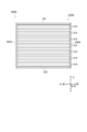
- the pleated filter 210 is 100 mm in the X-axis direction, 100 mm in the Y-axis direction, and approximately 3.5 mm in the Z-axis direction in Figure 1, one pleated filter 210 is formed by connecting approximately 143 rectangular pleated surfaces 213, each with a long side of 100 mm and a short side of 3.5 mm. Furthermore, when such a pleated filter 210 is stretched, the filter paper 211 has dimensions of 500 mm in the X-axis direction, 100 mm in the Y-axis direction, and 0.2 mm (thickness) in the Z-axis direction, as shown in Figure 4, with alternating mountain folds and valley folds 212 formed every 3.5 mm.
- the multi-filter unit 400 is formed by connecting multiple filter units 200 (filter units 200A) in which the upper plate 221 and the lower plate 222 have been removed, in a vertical and horizontal arrangement.
- Fig. 15 illustrates four rows in the W-axis direction and three rows in the H-axis direction, with the W-axis direction being 400 mm, the D-axis direction being 100 mm, and the H-axis direction being 300 mm.
- an upper plate 221A and a lower plate 222A are provided above the top filter unit 200A and below the bottom filter unit 200A, respectively, and are arranged across the entire W-axis direction.
- the filter units 200A that are adjacent to each other above and below are connected so that the rear end of the uppermost pleated filter 210 of the lower filter unit 200A and the rear end of the lowermost pleated filter 210 of the upper filter unit 200A are connected without any gaps between them.
- the rear end of the topmost pleated filter 210 of the topmost filter unit 200A and the rear end of the upper plate 221A are connected so as to fill the gap between them, and the rear end of the bottommost pleated filter 210 of the bottommost filter unit 200A and the rear end of the lower plate 222A are connected so as to fill the gap between them.
- the pleated filter 210 is compressed in the X-axis direction perpendicular to the folds 212, and is shortened in the X-axis direction compared to the pleated filter 210, and is referred to as a compressed filter 210A.
- pleated filter 210 is compressed in the X-axis direction perpendicular to folds 212, and is handled in the form of compressed filter 210A, which is a filter that is shorter in the X-axis direction compared to pleated filter 210, making each operation in the manufacturing process easier than if pleated filter 210 were handled as is.
- the usefulness of compressing the pleats in the X-axis direction lies mainly in the ease of handling during the manufacture of the filter unit 200 (especially in the fact that both ends can be easily held), so here we define the compressed state of the filter paper 211 in the compressed filter 210A as follows:
- the compressed filter 210A is easiest to handle when adjacent pleated surfaces 213 are in contact with each other, but depending on the hardness and thickness of the filter paper 211, adjacent pleated surfaces 213 may not come into contact with each other even when considerable pressure is applied. However, if the state does not shrink significantly even when a considerable pressure is applied, there is no significant difference in ease of handling from the state where adjacent pleat surfaces 213 are in contact with each other, and therefore, in addition to the case where adjacent pleat surfaces 213 are in contact with each other, if the state does not shrink significantly even when a considerable pressure is applied, it is considered to be in a fully compressed state.
- the fully compressed state refers to the following two states.
- the amount of shrinkage referred to here refers to the amount of shrinkage at the point when the gradually increasing force reaches 10 gf per 10 mm of the length of the filter paper 211 in the Y-axis direction.
- the semi-compressed state refers to the following state.
- a filter paper 211 that has been folded and has a crease 212 is placed on a plate D3 (made of aluminum) whose upper surface is a flat surface parallel to the XY plane, with one end side in the X-axis direction against a wall D1, and pressed in the X-axis direction (from back to front in Figure 16) from the other end side in the X-axis direction with a pressing plate D2, even if the pressing plate D2 is inclined 5 degrees upward, unlike in Figure 16 (when the upper end is inclined 5 degrees backward with respect to the YZ plane), pressing can be continued until the force required for pressing reaches 100 gf per 10 mm of length in the Y-axis direction.
- the state in which pressing can be continued means that pressing can be continued until the gradually increasing force reaches 100 gf per 10 mm of the length of the filter paper 211 in the Y-axis direction.
- the fully compressed state and the semi-compressed state are collectively referred to as the compressed state.
- the state in which the pleats are fixed in a fully compressed state is referred to as a fully fixed state
- the state in which the pleats are fixed in a semi-compressed state is referred to as a semi-fixed state
- the fully fixed state and the semi-fixed state are collectively referred to as a fixed state.
- a filter in which the pleats are in a fully compressed state is called a fully compressed filter
- a filter in which the pleats are in a semi-compressed state is called a semi-compressed filter
- both fully compressed filters and semi-compressed filters are included in the category of compressed filters.
- the compressed filter 210A is in a fully compressed or semi-compressed state as described above, whether or not the pleated surfaces 213 are in contact with each other.
- the compression filter 210A satisfies at least one of the following two conditions.
- the natural length (the length of compressed filter 210A in the X-axis direction when no force is acting on compressed filter 210A to expand or contract it in the X-axis direction) is less than half the length in the X-axis direction when in use (pleated filter 210).
- the natural length can be measured by placing compressed filter 210A on an aluminum plate with an upper surface that is a flat surface parallel to the XY plane, tapping the plate repeatedly to vibrate it, and measuring the length of compressed filter 210A in the X-axis direction when no change in the length of compressed filter 210A in the X-axis direction can be detected.
- the compressed filter 210A has 10 or more folds per 10 mm in the direction perpendicular to the folds (X-axis direction).
- Compressed filter 210A is shorter than pleated filter 210 in the X-axis direction perpendicular to folds 212, so it is easier to handle than pleated filter 210, and by stretching it, it can easily become pleated filter 210 that is longer in the X-axis direction than compressed filter 210A (for example, about five times longer). In addition, because it is compressed, it does not take up much space when transported, and by rolling it up in a roll, for example, it becomes easier to handle when selling it.
- the left and right plate-attached multi-stage inclined compression filter 500 is a semi-finished product manufactured up to step S3 in the manufacturing method described below. Note that a compression filter with plate-shaped members attached thereto is called a plate-attached compression filter.
- the multi-stage inclined compression filter 500 with left and right plates has 20 compression filters 210A arranged so that the X-axis and W-axis of the compression filters 210A coincide with each other, and when viewed from the W-axis direction, those compressed filters 210A are arranged diagonally upward from front to rear in the D-axis direction, and those diagonally downward from front to rear in the D-axis direction are arranged alternately, and these are arranged so that they contact each other at their ends in the D-axis direction, forming a zigzag shape when viewed from the W-axis direction.
- the 20 compressed filters 210A are arranged in an alternating line, with those arranged along a first direction ascending to the rear and those arranged along a second direction descending to the rear, when viewed from the W-axis direction perpendicular to the folds of the filter paper.
- the multi-stage inclined compression filter 500 with left and right plates has a right plate 223 adhered to the right end in the W-axis direction of the 20 compression filters 210A arranged as described above, and a left plate 224 adhered to the left end in the W-axis direction.
- the multi-stage inclined compression filter 500 with left and right plates is compressed in the W-axis direction compared to the completed filter unit 200, and has a small volume and is easy to handle. Therefore, by transporting, selling, etc., the multi-stage inclined compression filter 500 with left and right plates can be transported, sold, etc., and then completing the filter unit 200 through the processes from step S4 onwards, the costs incurred during transport, sales, etc. can be reduced.
- the multi-stage parallel compression filter 600 with left and right plates is similar to the multi-stage inclined compression filter 500 with left and right plates, except that the compression filters 210A are arranged in parallel.
- a multi-stage parallel compression filter 600 with left and right plates has 20 compression filters 210A arranged so that the X-axis and W-axis of the compression filters 210A coincide, and the Y-axis and D-axis coincide, all parallel when viewed from the W-axis direction, and equally spaced in the H-axis direction, with a right plate 223 bonded to the right end in the W-axis direction of the 20 compression filters 210A arranged in this manner, and a left plate 224 bonded to the left end in the W-axis direction.
- 50 compressed filters 210A each measuring 100 mm in the D-axis direction, 20 mm in the W-axis direction, and 5 mm in the H-axis direction can be attached at intervals of 7 mm in the H-axis direction to a right plate 223 and a left plate 224 measuring 100 mm in the D-axis direction and 350 mm in the H-axis direction, thereby manufacturing a multi-stage parallel compressed filter 600 with left and right plates comprising 50 compressed filters 210A.
- the compression filter 210A can be made into a pleated filter 210 by widening the space between the right plate 223 and the left plate 224.
- plate-like members are attached to the front and rear ends to connect the right plate 223 and the left plate 224, and the right plate 223, the left plate 224, the plate-like members attached to the front end, and the plate-like members attached to the rear end are then divided in the H-axis direction so that each pleated filter 210 is separated (20 equal parts in the H-axis direction if there are 20 compressed filters 210A, and 50 equal parts in the H-axis direction if there are 50 compressed filters 210A), resulting in the production of a single pleated filter 210 with plate-like members (front plate 225, rear plate 226, right plate 223A, and left plate 224A) attached to the front, back, left, and right.
- a filter unit 200B in which frame portions 220A are attached so as to surround the front, back, left and right of a single pleated filter 210, as shown in FIG.
- 50 filter units 200B can be manufactured in which pleated filters 210 are attached to frame portion 220A measuring 100 mm in the D-axis direction, 100 mm in the W-axis direction, and 7 mm in the H-axis direction.
- the compressed filters 210A used to manufacture the multiple filter units 200B can be combined into one, and compared to the multiple completed filter units 200B, it is compressed in the W-axis direction and has a small volume and is easy to handle. Therefore, by transporting, selling, etc., the multi-stage parallel compression filter 600 with left and right plates can be used to complete the multiple filter units 200B as described above, thereby reducing the costs incurred during transportation, sales, etc.
- a manufacturing method for manufacturing a filter unit 200 using 20 pleated filters 210 using the filter unit manufacturing system 100 of the embodiment includes a compressed filter manufacturing process (step S1-1), a compressed filter alignment process (step S1-2), a right plate and left plate attachment process (step S1-3), an opening process (step S1-4), an upper plate and lower plate attachment process (step S1-5), and a finishing process (step S1-6), as shown in FIG. 5.
- the filter unit manufacturing system 100 is a complete manufacturing line for manufacturing the filter unit 200, and as shown in FIG. 6 , includes a compressed filter manufacturing device 110, a compressed filter alignment device 120, a left and right plate mounting device 130, a temporary adhesion removal device 140, an upper and lower plate mounting device 150, and a finishing processing device 160.
- Step S1-1 Compressed filter manufacturing process
- the pleated filter 210 is compressed in the X-axis direction perpendicular to the folds 212, and is shortened in the X-axis direction compared to the pleated filter 210, and is referred to as a compressed filter 210A.
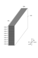
- compressed filter 210A shown in Figure 7 will have dimensions of 20 mm in the X-axis direction, 100 mm in the Y-axis direction, and 3.5 mm in the Z-axis direction.
- the thickness in the X-axis direction is 1/25, while the thickness in the Z-axis direction is 17.5 times; however, the thickness of the filter paper 211 is a value measured in accordance with Method A described in 6.1.1 of JIS L 1913:2010, and will become thinner if pressure is applied during the production of the compressed filter 210A.
- the filter paper 211 is continuously unwound from the filter paper roll 111 provided in the compressed filter manufacturing apparatus 110 (step S1-1-1).
- the filter paper roll 111 is configured so that a long length of filter paper 211, 100 mm wide and 0.2 mm thick, can be wound up and continuously unwound.
- the filter paper 211 unwound from the filter paper roll 111 is sent to the creasing device 112 as shown in FIG. 8, and is passed through the creasing device 112 to perform the creasing process (step S1-1-2).
- the creasing device 112 is formed by two meshing gears (a first gear 1121 and a second gear 1122). By passing the filter paper 211 between them, the filter paper 211 is creasing in the Y-axis direction by repeating alternating mountain and valley folds every 3.5 mm in the X-axis direction.
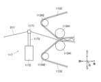
- the filter paper 211 that has been creased by the creasing device 112 is sent to the folding device 113 as shown in FIG. 8, and is passed through the folding device 113 to perform the folding process (step S1-1-3).
- the folding device 113 includes a first wall portion 1131, a second wall portion 1132, a belt 1133, and a plurality of rollers (first rollers 1134 and second rollers 1135), each of which is arranged symmetrically facing each other in the Z-axis direction.
- a shutter 1136 is provided near the rear end of the second wall portion 1132, allowing the space between the second wall portion 1132 to be freely opened and closed.
- the pair of first walls 1131 are arranged facing each other in the Z-axis direction, and are formed so that the facing surfaces are planar.
- the first wall portion 1131 is arranged so that the distance (distance in the Z-axis direction) between the opposing faces gradually increases as the filter paper 211 advances (from front to rear).
- the distance between the opposing faces of the first wall portion 1131 is narrower at the entrance portion (front end) to the space between them than the length (3.5 mm) in the direction perpendicular to the folds 212 of the pleated surface 213 of the compressed filter 210A to be formed, and at the exit portion (rear end) from the space between them, it is slightly wider than the length (3.5 mm) in the direction perpendicular to the folds 212 of the pleated surface 213 of the compressed filter 210A to be formed.
- the second wall portion 1132 is disposed behind the first wall portion 1131, and the pair of second wall portions 1132 are disposed facing each other in the Z-axis direction, and are formed so that the facing surfaces (second opposing surfaces 11321) are planar.
- the second wall portion 1132 is provided primarily for the purpose of filling the gap that occurs between the exit portion from the space between the belts 1133 and the fixing device 114, and connecting the two.
- the second wall portion 1132 is arranged so that the opposing surfaces (second opposing surfaces 11321) are parallel to each other and the distance between them (the distance in the Z-axis direction) is constant.
- the distance between the second opposing surfaces 11321 is the same as the length (3.5 mm) in the direction perpendicular to the folds 212 of the pleated surface 213 of the compressed filter 210A to be formed.
- the gap between the first wall portion 1131 and the second wall portion 1132 is as narrow as possible while still allowing the belt 1133 to pass through.
- the belt 1133 is a belt-shaped member having a constant width in the Y-axis direction that is the same as or greater than the width of the filter paper 211 in the Y-axis direction (100 mm), and is hung on a first roller 1134 and a second roller 1135, as shown in Figure 8, and is arranged so as to run along each of the opposing surfaces of the first wall portion 1131.
- a surface of a portion of the belt 1133 that faces the other belt 1133 in the Z-axis direction is defined as a first opposing surface 11331.
- the first opposing surface 11331 is planar along the first wall portion 1131.
- the belt 1133 is thin and lightweight, when the folded filter paper 211 pushes it from the inside (from the side facing the first opposing surface 11331) when folding the filter paper 211, it is pressed against the first wall portion 1131 as shown in FIG. 8.
- first opposing surfaces 11331 are considered to be arranged facing each other even if they are not parallel, as long as one of them intersects with the other when moved parallel to the surface. This also applies to the other components that make up this system.
- the belt 1133 may also be divided into multiple parts in the Y-axis direction, with multiple belts arranged in parallel with gaps in the Y-axis direction.
- the filter paper 211 is also folded at the creases 212 along the Y-axis direction, so the filter paper 211 will not fall into the gaps.
- the belt 1133 is sent in the direction of the filter paper travel (from front to rear) in the portion of the first opposing surface 11331 that runs along the opposing surfaces of the first wall portion 1131.
- the first opposing surface 11331 of the belt 1133 is formed into a surface having a certain width in the Y-axis direction, and a pair of first opposing surfaces 11331 are arranged facing each other, and as described below, the filter paper 211 is folded between them and compressed in the X-axis direction.
- the distance between the opposing surfaces of the first wall portion 1131 is narrower than 3.5 mm at the front end and slightly wider than 3.5 mm at the rear end, so that when the belt 1133 is pressed against the first wall portion 1131, the distance between the first opposing surfaces 11331 of the belt 1133 (distance in the Z-axis direction) is narrower than the length (3.5 mm) in the direction perpendicular to the folds 212 of the pleated surface 213 of the compressed filter 210A to be formed at the front end of the first opposing surface 11331 (the entrance portion to the space between them), and is approximately the same as the length (3.5 mm) in the direction perpendicular to the folds 212 of the pleated surface 213 of the compressed filter 210A to be formed at the rear end of the first opposing surface 11331 (the exit portion from the space between them), as shown in Figure 8. That is, the distance between the first opposing surfaces 11331 of the belts 1133 is narrowest (1 mm) at the entrance to
- the shutter 1136 is provided near the rear end of the second wall portion 1132 and is configured to allow the gap between the second wall portions 1132 to be freely opened and closed.
- the filter paper 211 that has been creased by the creasing device 112 is sent to the folding device 113 as shown in FIG. 8. Note that at this time, unlike FIG. 8, the gap between the second wall portions 1132 is closed by the shutter 1136.
- the filter paper 211 is first sent between a pair of first rollers 1134 (between a pair of belts 1133 that run from front to rear through that section), where it comes into contact with the belts 1133 and is sent rearward through the gap between the belts 1133.
- the leading edge of the filter paper 211 sent backward through the belts 1133 stops when it hits the shutter 1136 closing the gap near the rear end of the second wall portion 1132. Then, as shown in Fig. 8, the filter paper 211 is zigzag folded at the crease 212 made in step S1-1-2, and is folded and stacked between the second wall portion 1132 in front of the shutter 1136 in a compressed and shortened state in the X-axis direction compared to the pleated filter 211 to be formed.
- the filter paper 211 corresponds to the fully compressed state described above, and even if the filter paper does not correspond to the fully compressed state, it is preferable that the filter paper 211 corresponds to a quasi-compressed state, but this is not limited thereto. Regardless of the state of compression, the filter paper 211 is considered to be folded if it is folded along the crease.
- the meandering of the filter paper 211 in the Z-axis direction is restricted by the first opposing surfaces 11331 of a pair of belts 1133 arranged opposite each other, and the filter paper 211 is folded between the pair of belts 1133 arranged opposite each other.
- the first opposing surface 11331 of the belt 1133 flows from the front to the rear, so when the crease 212 of the folded filter paper 211 comes into contact with such a belt 1133, the filter paper 211 is sent from the front to the rear at the portion where it comes into contact with the belt 1133.
- the belt 1133 applies a frictional force to the filter paper 211 in the direction of travel of the filter paper 211 (from front to rear).
- the second opposing surfaces 11321 apply a frictional force to the filter paper 211 in the direction opposite to the traveling direction of the filter paper 211 (from rear to front).
- the filter paper 211 that has been creased by the creasing device 112 can be pulled into the space between the belts 1133 by the frictional force of the belts 1133, and by folding the filter paper 211 in the space between the belts 1133, when the crease 212 of the filter paper 211 comes into contact with the belt 1133, the frictional force generated between the belt 1133 and the filter paper 211 acts as a force to compress and fold the filter paper 211 in the X-axis direction.
- the shutter 1136 When a predetermined amount of filter paper 211 is stacked in a folded state in front of the shutter 1136, the shutter 1136 is opened and the filter paper 211 in this state is sent to the fixing device 114 as shown in FIG. 8, and is strengthened and fixed by passing through the fixing device 114 (step S1-1-4).
- the folded filter paper 211 is pushed out to the rear fixing device 114, and is then pushed out at a constant speed by the output roller 115 to the cutting device 116.
- a stable state is reached in which the filter paper 211 is folded at a constant speed determined mainly by the frictional force of the belt 1133 and the speed at which the filter paper 211 is fed backwards by the output roller 115. This state is referred to as the "steady state.”
- the shutter 1136 is not essential and is only temporarily required until the steady state is reached.
- the shutter 1136 may be omitted and a pre-folded filter paper 211 or an appropriate padding equivalent thereto may be placed at a position from the position of the shutter 1136 to the fixing device 114.
- the tip of the filter paper 211 hits the stuffing at the position of the shutter 1136, causing the filter paper 211 to be folded between the belts 1133, and the folded filter paper 211 piles up at the position of the shutter 1136.
- the stuffing begins to move backwards, and when it eventually passes through the fixing device 114, it is pushed out by the output roller 115 to the cutting device 116.
- the cutting device 116 is filled with folded filter paper 211, a steady state is reached.
- the temporary bonding device 1141 is a device for fixing the distance between the pleated surfaces 213 located at the front and rear when the filter paper 211 is in a folded state.
- the temporary adhesive device 1141 fixes the filter paper 211 in a state folded by the folding device 113 or in a state close to that state by adhering the folds 212 located at the front and rear of both ends (upper and lower surfaces) in the Z-axis direction of the folded filter paper 211.
- adhesive may be applied in the form of a thread or a surface extending in the X-axis direction to the upper and lower surfaces of the filter paper 211 in a state folded by the folding device 113 or in a state close to that state, and the adhesive may be used to adhere the folds 212.
- the entire crease 212 in the Y-axis direction is bonded, and only a part of the crease 212 in the Y-axis direction may be bonded. Also, it is preferable to bond the creases 212 to each other at both ends (upper and lower surfaces) in the Z-axis direction of the folded filter paper 211, but it is also possible to bond the creases 212 to each other only on either the upper surface or the lower surface.
- the filter paper 211 is fixed in the state in which it is folded by the folding device 113, or in a state close to that state.
- the filter paper 211 may be fixed only by heat treatment using the heat treatment device 1142, without going through the temporary adhesion process using the temporary adhesion device 1141.
- the filter paper 211 may be heated with the creases 212 folded, and then cooled immediately after heating, thereby fixing the shape of the filter paper 211, so that the filter paper 211 is fixed in the folded state by the folding device 113, or in a state close to that state.
- the filter paper 211 may be vibrated after being folded in step S1-1-3 so that the pleated surfaces 213 are in contact with each other, causing adjacent pleated surfaces 213 to rub against each other and entangle the fibers protruding from the pleated surfaces 213, thereby fixing the filter paper 211 in the state in which it was folded by the folding device 113 or in a state close to that state.
- the filter paper 211 which has been fixed in a folded state by the temporary adhesive device 1141, is sent to the heat treatment device 1142 as shown in FIG. 8, where it is heated as part of the strengthening and fixing process.
- the heat treatment device 1142 has a pair of heating plates, which are plate-shaped members capable of heating the parts of the filter paper 211 that they come into contact with, arranged facing each other in the Z-axis direction. This allows the entire creases 212 located above and below the folded filter paper 211 to be heated.
- the heat treatment device 1142 heats both ends of the folded filter paper 211 in the Z-axis direction where the creases 212 exist, thereby removing distortion at the creases, and the shape can be stabilized by subsequent cooling.
- the force that causes the filter paper 211 to return to the compressed filter 210A state can be strengthened (the force that causes it to expand in the X-axis direction can be weakened) after the opening process (step S1-4) described below.
- the heat treatment device 1142 may use a plate-shaped heating plate to heat only the fold 212 as described above and then cool it, but various other common heat treatment techniques can also be used.
- the filter paper 211 that has been strengthened and fixed by the fixing device 114 is sent to the cutting device 116 by the output roller 115, and is cut at intervals of 20 mm in the X-axis direction by the cutting blade 1161 (step S1-1-5).
- the frictional force acting on the filter paper 211 from the belts 1133 is at its maximum, so the filter paper 211 is in a state of being most compressed in the X-axis direction.
- the compression of the filter paper 211 in the X-axis direction is gradually alleviated by friction of the second wall portion 1132 and friction of subsequent devices.
- the compression rate in the X-axis direction (the ratio of the length in the X-axis direction of the filter paper 211 in an extended state to the length in the X-axis direction of the filter paper 211 in a folded state) will be the same when the filter paper 211 is located at the exit of the space between the belts 1133 and when it is located in the space between the output rollers 115; however, if frictional force is applied at a specific point between these points, the compression rate of the filter paper 211 in the X-axis direction from that point to the output roller 115 will be lower than the compression rate of the filter paper 221 in the X-axis direction from the exit of the space between the belts 1133 to that point.
- the term "a state close to that state refers to the state in which the compression rate decreases due to subsequent frictional forces from the state folded by the folding device 113.
- the compression rate of the filter paper 211 in the X-axis direction just before the output roller 115 is determined by the ratio of the input speed of the filter paper 211 to the folding device 113 and the output speed of the filter paper 211 from the cutting device 116.
- the filter paper 211 is folded in the fully compressed state described above near the exit of the space between the first opposing surfaces 11331 of the belts 1133, but the compression ratio gradually decreases due to frictional forces experienced in subsequent processes. However, it is preferable that at least the semi-compressed state described above is maintained when fixed by the fixing device 114.
- Step S1-2 Compression filter alignment process
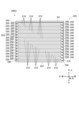
- the compressed filter 210A shown in FIG. 7 is arranged so that the X-axis and W-axis of the compressed filter 210A coincide with each other, and when viewed from the W-axis direction, the compressed filter 210A is arranged so that the filters are arranged diagonally upward from the front to the rear in the D-axis direction and diagonally downward from the front to the rear in the D-axis direction alternate, and these filters are arranged so that they alternate at their ends in the D-axis direction and form a zigzag shape when viewed from the W-axis direction.
- the compressed filters 210A can be arranged as shown in FIG. 9 by storing 20 compressed filters 210A in a container with slits arranged in a zigzag pattern.
- Step S1-3 Right and left plate attachment process
- step S2 for the 20 compressed filters 210A arranged as shown in Figure 9, a right plate 223 is adhered to the right end in the W axis direction and a left plate 224 is adhered to the left end in the left and right plate attachment device 130 provided in the filter unit manufacturing system 100.
- a hot melt adhesive can be used, which is applied to the right plate 223 and the left plate 224 and then pressed against the 20 compressed filters 210A arranged as shown in FIG. 9.
- the pleated surface 213 at the right end of each compressed filter 210A is adhered without gaps to the right plate 223, and the pleated surface 213 at the left end is adhered without gaps to the left plate 224.
- the left plate 224 coated with adhesive is placed on a horizontal surface, and one end of the 20 compressed filters 210A that were stored in the container with the slits arranged in step S2 and aligned is pressed against the left plate 224 and glued. Thereafter, the container is removed, and the 20 compressed filters 210A are left standing on the left plate 224, and then the right plate 223 coated with adhesive is pressed against them from above to adhere them.
- the compressed filter 210A since the compressed filter 210A is compressed in the W-axis direction, it becomes easier to press the right plate 223 against the pleated surface 213 at the right end of each compressed filter 210A, and it becomes easier to press the left plate 224 against the pleated surface 213 at the left end of each compressed filter 210A, so that the connection strength between the right plate 223 and the left plate 224 and the compressed filter 210A can be improved.
- step S3 By going through the process up to step S3, it is possible to manufacture a multi-stage inclined compression filter 500 with left and right plates as shown in Figure 17, as described above.
- the container that stores the compressed filter 210A in step S2 can fix the stored compressed filter 210A to the container by, for example, adjusting the width of a slit using a piezoelectric element so that the stored compressed filter 210A does not move.
- the left plate 224 is adhered as described above, and then the fixation is released and the container is pulled out.
- Step S1-4 Opening Process Next, in the temporary adhesion removal device 140 provided in the filter unit manufacturing system 100, the temporary adhesion between the pleated surfaces 213 of each of the 20 compressed filters 210A, which have their right and left plates 223 and 224 bonded together in step S3, is released and the filters are stretched and spread out in the W-axis direction.
- the gap between the right plate 223 and the left plate 224 is widening to approximately 300 mm, the adhesion between adjacent pleat surfaces 213 in the compressed filter 210A is released, and then the gap between the right plate 223 and the left plate 224 is returned to 100 mm, which is the gap in the filter unit 200.
- the adhesive between the pleated surfaces 213 of the compressed filter 210A is released, and the spacing between the pleated surfaces 213 is adjusted accordingly, thereby producing the 20 pleated filters 210 that are included in the filter unit 200.
- the tension that tends to shrink the pleated filter 210 in the W-axis direction can be maintained to a degree that allows the pleated filter 210 to maintain its shape.
- step S4 each compressed filter 210A is stretched in the W-axis direction to become a pleated filter 210, and then the upper and lower plates 221 and 222 are attached in the upper and lower plate attachment device 150 provided in the filter unit manufacturing system 100.
- the upper plate 221 is attached to the upper ends of the right plate 223 and the left plate 224 so as to straddle them
- the lower plate 222 is attached to the lower ends of the right plate 223 and the left plate 224 so as to connect them.
- the attachment method is not particularly limited as long as no gaps are created between the upper plate 221 and the right plate 223, between the upper plate 221 and the left plate 224, between the lower plate 222 and the right plate 223, and between the lower plate 222 and the left plate 224, and may be bonded using, for example, a specific type of adhesive.
- step S5 Finishing Processing Step
- step S5 with the upper plate 221 and the lower plate 222 attached, finishing processing is carried out in the finishing processing device 160 provided in the filter unit manufacturing system 100, and the filter unit 200 is completed. Specifically, the following processing is performed.
- the air intake section 230 includes the portions between the connections (sealing sections 250) between the pleated filters 210, the portion between the front end of the upper plate 221 and the topmost sealing section 250, and the portion between the front end of the lower plate 222 and the bottommost sealing section 250. These are openings for air circulation, so all other portions are sealed by covering them with hot melt approximately 3 mm thick.
- a container is prepared in which grooves are formed on the front surface of the filter unit 200, the front ends of the upper plate 221, the lower plate 222, the right plate 223, and the left plate 224, and in a shape corresponding to the sealing portion 250. That is, such a container has a flat bottom surface in which square grooves are formed corresponding to the front ends of the upper plate 221, the lower plate 222, the right plate 223, and the left plate 224, and within such a square groove, ten parallel grooves corresponding to the ten sealing portions are formed, connecting opposing sides.
- the groove depth is about 5 mm, and the parallel grooves corresponding to the 10 sealing parts each become narrower as they go downwards.
- Low viscosity hot melt is poured into these grooves until they are filled to a depth of about 2 mm, and the semi-finished product that has been completed up to step S5 is inserted front-side down into the groove, and is removed after the hot melt has solidified.
- the parallel grooves corresponding to the ten sealing parts are formed so that their width narrows as they go downward, making it possible to flatten the pleats at the front end of the pleated filter 210. This narrows the vertical width of the sealing part 250, improving the opening rate of the air intake part 230.
- the same process can be performed on the rear surface of the filter unit 200.
- the filter paper 211 is folded between a pair of belts 1133 provided in the folding device 113 with its meandering in the Z-axis direction being restricted.
- the belts 1133 are configured to move in the direction in which the filter paper 211 moves (from front to rear), and the filter paper 211 is folded between them. This means that when the filter paper 211 comes into contact with the belts 1133, no frictional force is generated in a direction that stops the movement of the filter paper 211, but rather a frictional force is generated in a direction that causes the filter paper 211 to move forward. This makes the movement of the filter paper 211 between the belts 1133 smoother, and further improves the manufacturing efficiency of pleated filters.
- the folds of the filter paper 211 that is gradually folded as shown in FIG. 8 can be kept in contact with the belts 1133 for a longer period of time, further improving the effect of the frictional force of the belts 1133 propelling the filter paper 211 forward.
- step S1-1-2 in which the filter paper 211 is creased in advance in the compression filter manufacturing process in step S1-1, prior to the folding step in step S1-1-3, the locations at which the filter paper 211 will be folded in the folding process can be determined in advance, and irregular folding can be prevented, further improving the manufacturing efficiency of the pleated filter.
- the compressed filter 210A folded in the folding process of step S1-1-3 in the compressed filter manufacturing process of step S1-1 is stretched and unfolded in a direction perpendicular to the crease 212 (the X-axis direction in Figure 7) in the opening process of step S4 to form the pleated filter 210, after the right plate 223 and the left plate 224, which are part of the frame portion 220, are attached in the right plate and left plate attachment process of step S3.
- the distance between the pleated surfaces of a pleated filter paper increases, thereby lengthening the length of the filter paper in the direction perpendicular to the folds, this is considered to include the filter paper being unfolded.
- a pleated filter without any frame attached is difficult to handle and difficult to attach the frame to, as its shape easily changes.
- the filter is relatively easy to handle and easier to attach the frame to. Therefore, by attaching at least a portion of the frame with the length in the direction perpendicular to the fold shortened and then expanding it, the pleated filter becomes easier to handle during the manufacturing process of the filter unit, which is a product that includes a pleated filter, and the manufacturing efficiency of such products can be improved.
- the compressed filter 210A is temporarily fixed in a folded state, and then in the opening process of step S4, the filter paper 211 is released and unfolded.
- the portion of the crease 212 formed in the folded filter paper 211 in step S1-1-3 is heated, thereby removing distortion in the crease 212 of the folded filter paper 211, and the shape of the compressed filter 210A that is formed can be adjusted. Furthermore, the shape of the compressed filter 210A can be stabilized in the folded state in step S1-1-3, and the tension that causes the pleated filter 210 to shrink in the W-axis direction can be strengthened after the release process step S4 (the force that causes the pleated filter 210 to expand in the W-axis direction can be weakened), making it easier to maintain the shape of the pleated filter 210 in the filter unit 200.
- step S3 the right and left plates 223 and 224 are attached to both ends of the compressed filter 210A in the direction perpendicular to the fold 212 (X-axis direction), and then the gap between them is widened in the opening process of step S4, making it easier to unfold the compressed filter 210A.
- the compressed filters 210A manufactured in step S1-1 are arranged so that, when viewed from the W axis direction, they are arranged diagonally upward from the front to the rear in the D axis direction, and diagonally downward from the front to the rear in the D axis direction, alternating, making it possible to manufacture a filter unit 200 in which multiple pleated filters 210 are connected alternately at the front and rear.
- the filter paper 211 is folded into pleats, and compared to the state during use (pleated filter 210), it is compressed in a direction perpendicular to the folds 212 of the filter paper 211 (X-axis direction) and shortened, making it less likely to deform and easier to handle compared to the state in which it is unfolded to form pleated filter 210. Therefore, by carrying out steps S2 and S3 of the manufacturing process for filter unit 200, which is a product including pleated filter 210, in this compressed filter 210A state, it is possible to make the filter easier to handle during the manufacturing process of filter unit 200.
- the compressed filter 210A is even less susceptible to deformation, making it even easier to handle during the manufacturing process of the filter unit 200.
- the cross section of the pleated surface is linear, whereas when a double pleat is formed as in this embodiment, the cross section of the pleated surface of the secondary pleat becomes zigzag due to the primary pleat, so the line length of the cross section of the pleated surface becomes longer, and the area of the filter paper 211 that can be used in the filter can be increased proportionately.
- the air blowing direction (the direction in which air is introduced from the air inlet 230 into the frame 220) is the D-axis direction, which is a direction along the pleat creases 212 of the pleated filter 210, so that the resistance that the circulating air experiences from the pleat creases and each pleat surface can be reduced, and the increase in air resistance caused by the multiple pleats can be suppressed.
- the pleated filter 210 is arranged at an angle to the D-axis direction, the air introduction direction (D-axis direction) and the extension direction of the folds 212 (directions inclined up and down from the D-axis) are not completely parallel.
- this is considered to be included in the case where the direction of air introduction from the air introduction section 230 into the frame section 220 is a direction along the pleat folds of the pleated filter 210.
- the sealing portions 250 which correspond to the folds of the secondary pleats, are positioned to face the air inlet portion 230 or the air outlet portion 240, making it possible to smoothly introduce and exhaust air between the sealing portions 250.
- the right ends of all pleated filters 210 are connected to the right plate 223, the left ends are connected to the left plate 224, the rear end of the topmost pleated filter 210 is connected to the upper plate 221, and the rear end of the bottommost pleated filter 210 is connected to the lower plate 222, so that the entire filter formed by the multiple pleated filters 210 can be attached to the frame portion 220 without creating any gaps between them.
- step S1-1 the filter paper 211 is folded, strengthened, fixed and cut using the folding device 113, the fixing device 114, the output roller 115 and the cutting device 116 to manufacture the compressed filter 210A.
- the compressed filter 210A may be manufactured using a more basic simplified compressed filter manufacturing apparatus 300 as shown below.
- the simplified compressed filter manufacturing device 300 is equipped with a compression section 310 in which two parallel plates 311 measuring 550 mm in the X-axis direction and 100 mm in the Y-axis direction are arranged with a gap of 3.5 mm in the Z-axis direction.
- the parallel plates 311 are made of a material with a small coefficient of dynamic friction, and are formed so that the opposing surfaces are flat.
- the rear end of the compression section 310 is formed with a first gate 320, which is a section where the spacing in the Z-axis direction is reduced to 3.0 mm, and the opening of the first gate 320, which is spaced 3.0 mm apart, is provided with a shutter 330 that allows the opening to be opened and closed.
- the first filter paper 211 is set in a stretched state so that its tip reaches near the first gate 320.
- the shutter 330 provided on the first gate 320 is closed, and the push plate 370 is moved backward to push in the filter paper 211.
- the filter paper 211 is folded alternately at the creases 212 formed at 3.5 mm intervals, with the parallel plates 311 restricting the filter paper 211 from meandering in the Z-axis direction, and as shown in FIG. 13C, the filter paper 211 is pressed against the shutter 330 with each pleat surface 213 in contact or close proximity.
- the shutter 330 is opened. Then, the filter paper 211, which is folded so that each pleat surface 213 is in contact with each other, is pushed by the push plate 370 out of the first gate 320 and sent to the temporary adhesive section 340.
- the second filter paper 211 After the first filter paper 211 is pushed out from the first gate 320, the second filter paper 211 is set as shown in FIG. 13A and the same process is carried out. Furthermore, by carrying out the same process for the third, fourth and subsequent filter papers 211, compressed filters 210A measuring 20 mm in the X-axis direction, 100 mm in the Y-axis direction and 3.5 mm in the Z-axis direction as shown in FIG. 7 can be manufactured one after another.
- the push plate 370 is used as a means for pushing the filter paper 211 backward within the compression section 310 to fold it, but the means for pushing the filter paper 211 is not limited to the push plate 370.
- air may be sprayed from the entrance to the exit of the compression section 310 (front to rear) to push the filter paper 211 by the air pressure.
- the filter paper 211 may be pushed by the frictional force of a surface that moves from front to rear, such as the belt 1133 provided in the folding device 113 described above.
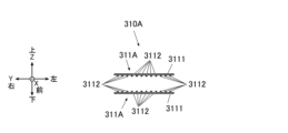
- the parallel plate 311A may be provided with a flat surface portion 3111 and a protrusion portion 3112 which is a stripe-like protrusion extending in the X-axis direction, as in the compression portion 310A shown in FIG. 14.
- the protrusions 3112 are formed on one surface of the planar portion 3111, extending in the X-axis direction and arranged in multiple rows in the Y-axis direction, and the parallel plates 311A are arranged so that the surfaces of the planar portion 3111 on which the protrusions 3112 are formed face each other.
- the pair of parallel plates 311A are arranged so that the distance between the planar portions 3111 is 5.0 mm, and the distance between the tips of the protrusions 3112 is 3.5 mm.
- the flat portion 3111 is not essential and may be removed. In this case, only the protrusion 3112 in FIG. 14 remains, and the compression section is formed by arranging multiple elongated plates in a stripe shape above and below the filter paper 211. Regardless of whether or not the flat portion 3111 is present, a stripe shape is defined as a state in which multiple members that are longer in one direction (X-axis direction) than in a second direction (Y-axis direction) perpendicular to the first direction are arranged at intervals in the two directions.
- each of the elongated plates with only the protrusions 3112 remaining is formed so that its width is wider in the Z-axis direction perpendicular to the surface of the filter paper 211 before folding in the compressed section than in the Y-axis direction perpendicular to this. This makes it easier for such plates to bend in the Y-axis direction when they expand due to factors such as thermal expansion, and prevents the spacing of the compressed sections in the Z-axis direction from changing due to bending in the Z-axis direction.
- one of the compressed sections can be formed by arranging four elongated plates that are 10 mm wide in the Y-axis direction, wider in the Z-axis direction than in the Y-axis direction, and 550 mm long in the X-axis direction at intervals of 20 mm in the Y-axis direction, and two sets of these arranged one above the other to form the compressed section.
- the creases 212 formed in the filter paper 211 extend in the Y-axis direction, there is no need to restrict movement in the Z-axis direction throughout the entire Y-axis direction. However, if it is possible to restrict movement in the Z-axis direction over a portion of the Y-axis direction, it is possible to restrict the movement of the filter paper 211 in the Z-axis direction and prevent the filter paper 211 from meandering in the Z-axis direction.
- any member that is placed on both sides (upper and lower) of the filter paper 211 and is capable of restricting the movement of the filter paper 211 in a direction perpendicular to the surface of the filter paper 211 before folding (the Z-axis direction) will qualify as a restricting member that restricts the movement of the filter paper 211 in the Z-axis direction when it is folded, regardless of whether it is plate-shaped or not.
- the position of the protrusion 3112 cannot be fixed if only the protrusion 3112 remains, it is also possible to leave only the peripheral portion (front, rear, left and right ends) of the flat surface portion 3111 in a frame shape, and connect the protrusion 3112 to such a frame at the front and rear ends.
- the top and bottom surfaces of the filter paper 211 are exposed during the folding process, making it possible to apply heat, light, etc. from above and/or below the filter paper 211 during folding, expanding the range of processing that can be performed.
- the filter paper 211 can be folded while being heated by applying hot air from above and below.
- the filter paper 211 it is most preferable to compress the filter paper 211 between two surfaces that are arranged facing each other and move in the X-axis direction (from front to rear), such as the belt 1133 provided in the folding device 113 of the above-mentioned filter unit manufacturing system 100.
- the oscillating device 117 includes an oscillating part 1171 having a slit 11711 through which the filter paper 211 can pass, a base 1172, and a connecting shaft 1173 that connects the oscillating part 1171 and the base 1172, and is configured so that the oscillating part 1171 oscillates in the Z-axis direction relative to the base 1172.
- the oscillating device 117 is positioned in front of the entrance to the space between the two belts 1133 of the folding device 113, and is configured to move the oscillating part 1171 up and down at a frequency f (f oscillations per second) with the filter paper 211 passing through the slit 11711 of the oscillating part 1171.
- the width in the Z-axis direction of the compressed filter 210A to be manufactured (in this case, the distance between the second opposing surfaces 11321 of the second wall portion 1132 of the folding device 113 (the distance at the exit of the space between the belts 1133) is h (mm)
- the introduction speed of the filter paper 211 to the folding device 113 (the payout speed of the filter paper 211 from the filter paper roll 111) is v (mm/s)
- the filter paper 211 is oscillated in the Z-axis direction
- the filter paper 211 is oscillated up and down in 5 mm increments in the X-axis direction
- the filter paper 211 is folded at 5 mm intervals in the folding device 113, and a compressed filter 210A with a height in the Z-axis direction of 5 mm can be manufactured.
- step S1-1-2 it is preferable to include either the creasing step of step S1-1-2 or the step of rocking the filter paper 211 as described above, but it is possible to omit the creasing step of step S1-1-2 and not carry out the step of rocking the filter paper 211 as described above.
- the belt 1133 flows from front to rear in the folding device 113, so that the filter paper 211 is sent from front to rear and stacked in front of the gate 1135, and the meandering of the filter paper 211 in the Z-axis direction is restricted by the belt 1133. Therefore, although the accuracy of the position of the crease 212 (uniformity of the size of each pleat surface 213) decreases, it is still possible to fold the filter paper 211.
- the filter paper 211 will be folded between the belts 1133, but the way it is folded will differ depending on the relationship between the spacing of the belts 1133 and the thickness of the filter paper 211.
- FIG. 22 is an explanatory diagram showing the difference in folding method depending on the relationship between the spacing of the belts 1133 of the folding device 113 and the thickness of the filter paper in the folding process of step S1-1-3.
- the spacing of the belts 1133 is set to be constant.
- FIG. 22A illustrates a case where the thickness of the filter paper 211 is approximately half the spacing between the belts 1133.
- the way in which the filter paper 211 is folded is unlikely to be other than a pleated shape in which the width of the pleated surface 213 is approximately the same as the spacing between the belts 1133, so there is little need to go through the creasing process of step S1-1-2 or the process of rocking the filter paper 211 as described above.
- FIG. 22B illustrates a case where the thickness of the filter paper 211 is significantly smaller than the spacing of the belts 1133.
- the way in which the filter paper 211 is folded is not necessarily limited to a pleated shape in which the width of the pleated surface 213 is approximately the same as the spacing of the belts 1133, and as shown in FIG. 22B, creases may occur at the upper or lower end that are pulled in the direction of travel of the belt.
- the thickness of the filter paper 211 is approximately 0.2 to 0.6 times the spacing of the belts 1133, it is unlikely that the filter paper will be folded into any shape other than pleats, as shown in Figure 22A, and if the thickness of the filter paper 211 is less than 0.2 times the spacing of the belts 1133, creases are likely to occur that are pulled in the direction of belt movement, as shown in Figure 22B. Therefore, in the latter case, although not essential, the necessity of going through the folding step in step S1-1-2 and the step of shaking the filter paper 211 as described above is higher than in the former case.
- This method only involves a process of fixing the shape of the folds 212 by heating and then cooling. Specifically, the folds 212 are heated to a temperature according to the material of the filter paper 211 to plastically deform the folds 212, and then the deformation is fixed by returning the folds 212 to room temperature.
- (b) Second Method This is a method in which only a temporary bonding process is performed using an adhesive. That is, by applying an adhesive to the surface, the folds 212 and the side ends (ends in the Y-axis direction) of the folded filter paper 211 are joined together.
- a hot melt adhesive such as paraffin
- a melting temperature of 120 degrees or less can be used as the adhesive, and this hot melt can be applied to the top and bottom surfaces in a line extending in the X-axis direction.
- an auxiliary material is used. That is, an auxiliary material made of another material is layered on the filter paper 211, and then a process according to the material of the auxiliary material is carried out to bond the auxiliary materials together, thereby gently bonding the pleated surfaces 213 together.
- This method strengthens the folding device 113 and strongly compresses the filter paper 211 in the X-axis direction.
- a device hereinafter referred to as a "compression device” may be provided behind the folding device 113 in which the distance between the first opposing surfaces 11331 of the belts 1131 of the folding device 113 is kept constant at 3.5 mm. The filter paper 211 folded by the folding device 113 can then be further compressed in the X-axis direction by such a compression device, thereby making it unnecessary to carry out a separate fixing process as described above.
- This method omits the strengthening and fixing process in step S1-1-4. That is, if a strong material (such as a metal mesh) that undergoes plastic deformation at room temperature is layered on the filter paper 211 as a reinforcing sheet and the filter paper 211 is folded, the filter paper 211 is reinforced by the reinforcing sheet and fixed in the folded state, so there is no need to perform a separate strengthening and fixing process in step S1-1-4.
- a strong material such as a metal mesh
- (b) Multi-filter unit When manufacturing a multi-filter unit 400 as shown in Fig. 15, first, a plurality of semi-finished products (multi-stage inclined compression filter 500 with left and right plates with an increased distance between right plate 223 and left plate 224) manufactured through step S4 are prepared. When manufacturing a multi-filter unit 400 in which filter units 200A are arranged in four rows in the W-axis direction and three rows in the H-axis direction as shown in Fig. 15, 12 units are prepared.
- the prepared semi-finished products are arranged according to their arrangement in the multi-filter unit 400 to be manufactured. If a multi-filter unit 400 is to be manufactured in which the filter units 200A are arranged in four rows in the W-axis direction and three rows in the H-axis direction as shown in FIG. 15, then the filter units 200A will be arranged in four rows in the W-axis direction and three rows in the H-axis direction.
- an upper plate 221A is attached to the upper ends of the aligned semi-finished products so as to cover the entire upper ends
- a lower plate 222A is attached to the lower ends so as to cover the entire lower ends.
- the finishing process is carried out.
- the finishing process is the same as that described in step S6, except for the size of the container and the shape of the groove.
- a container is prepared with a groove formed in it that corresponds to the shape of the part other than the air circulation opening, and the groove is filled with hot melt.
- Multiple containers are lined up, and semi-finished products with upper plate 221A and lower plate 222A attached are inserted into such grooves to cover the entire part other than the air circulation opening. This process is carried out on both the front and rear sides, and all parts of both the front and rear sides other than the air circulation opening are sealed.
- the filter paper 211 broadly includes sheet-like members capable of removing particles to be removed from a fluid.
- the filter paper 211 may be a membrane filter.
- the membrane filter is composed of an MF membrane (microfiltration membrane), an RO membrane (reverse osmosis membrane), or the like.
- the filter paper 211 is a membrane filter, it is preferable to provide a reinforcing material since it is a thin film.
- a nonwoven fabric made of polypropylene fibers can be used as the reinforcing material.
- the filter unit 200 may be any fluid and is not limited to air.
- the filter unit 200 may be a gas other than air or a liquid.
- a filter unit in which double pleats are formed in the filter as in this embodiment can easily be made longer in depth, and when used to filter liquids in pipes, it is easy to fully enjoy the benefits of an increased effective area provided by the pleated filter.
- the block filter is preferably formed by stacking a plurality of compressed filters in the Z-axis direction such that the folds are in contact with each other.
- the block filter has a rectangular parallelepiped shape that is longer in the Z-axis direction than one compressed filter.
- Block filters are extremely portable because they allow long, large pieces of filter paper to be packed into a compact container.
- a single multi-stage parallel compression filter 600A with left and right plates (described below) (multiple compression filters 210A stacked in the Z-axis direction) is called a monoblock filter 700.
- a polyblock filter 800 is made up of multiple monoblock filters 700 connected together.
- a typical example is a three-dimensional assembly (multiple monoblock filters 700 connected together in the X-axis, Y-axis, and Z-axis directions), but this is not limited to this and may also include a polyblock filter 800 in which multiple monoblock filters 700 are connected together in only one or two directions.
- multiple monoblock filters 700 can be manufactured.
- the internal dimensions of a container used for transporting or storing a block filter be set in the X-axis direction so that when the block filter is stored in the container, each compressed filter that makes up the block filter is in a fully compressed state. This also applies to containers used for transporting and storing compressed filters that are not block filters.
- a filter unit 200C according to a second embodiment of the present disclosure has 28 pleated filters 210 housed in a frame 220, as shown in FIGS. 25 to 27 .
- the filter unit 200C is for removing particles to be removed from the air by circulating air in the front-to-rear direction, and as shown in Figures 25 to 27, it is equipped with 28 pleated filters 210 arranged so that the X axis coincides with the W axis, the Y axis coincides with the D axis, and the Z axis coincides with the H axis, and a frame portion 220 arranged so that an upper plate 221 is located on the upper side, a lower plate 222 is located on the lower side, a right plate 223 is located on the right side, a left plate 224 is located on the left side, an air intake portion 230 is located on the front side, and an air exhaust portion 240 is located on the rear side.
- the right ends of all the pleated filters 210 are connected to the right plate 223, and the left ends of all the pleated filters 210 are connected to the left plate 224.
- the 28 pleated filters 210 are arranged so that the pleats are parallel to the D axis (front-to-back direction), the DW plane of the filter unit 200C as shown in Figure 25 is parallel to the XY plane of the pleated filter 210 as shown in Figure 1, and in adjacent pleated filters 210, the folds 212 located on the lower side of the upper pleated filter 210 and the folds 212 located on the upper side of the lower pleated filter 210 are positioned at approximately the same height in the H axis direction.
- the upper plate 221, the uppermost pleated filter 210 to the lowermost pleated filter 210, and the lower plate 222 are connected alternately front to back when viewed from the W-axis direction to form the sealing section 250, and when the 28 pleated filters 210 are viewed as a whole, pleats are formed in which concave portions that are concave toward the front and convex portions that are convex toward the front are alternately repeated in the H-axis direction when viewed from the front (concave portions that are concave toward the rear and convex portions that are convex toward the rear are alternately repeated in the H-axis direction when viewed from the rear).
- the pleats formed individually on the 28 pleated filters 210 become primary pleats, and the pleats formed by the 28 pleated filters 210 become secondary pleats with a larger pitch than the primary pleats, and when the 28 pleated filters 210 are viewed as a whole, they constitute a filter formed by overlapping primary pleats and secondary pleats.
- the air introduction direction from the air introduction section 230 and the direction along the folds of the primary pleats are both parallel to the D-axis direction.
- a front connecting column 260 is formed on the front surface of the filter unit 200C, connecting the W-axis direction center of the front end of the upper plate 221, the W-axis direction center of the front end of each pleated filter 210 (the W-axis direction center of each sealing portion 250 on the front side), and the W-axis direction center of the front end of the lower plate 222.
- the front connecting column 260 is integral with each sealing portion 250 on the front side and is formed from hot melt adhesive several mm thick.
- a rear connecting post 270 is formed on the rear surface of the filter unit 200C, connecting the W-axis direction center of the rear end of the upper plate 221, the W-axis direction center of the rear end of each pleated filter 210 (the W-axis direction center of each rear sealing portion 250), and the W-axis direction center of the rear end of the lower plate 222.
- the rear connecting post 270 is integral with each rear sealing portion 250 and is formed from hot melt adhesive several mm thick.
- each of which has 28 pleated filters 210 arranged in parallel, each spaced 3.5 mm apart in the Z direction, from a compressed filter 210B measuring 1000 mm in the X direction, 200 mm in the Y direction, and 3.5 mm in the Z direction, via a polyblock filter 800 measuring 1000 mm in the X direction, 200 mm in the Y direction, and 98 mm in the Z direction, to a filter unit 200C measuring 100 mm in the D direction, 100 mm in the W direction, and 100 mm in the H direction.
- the manufacturing method for producing the filter unit 200C having 28 pleated filters 210 includes the steps shown in FIG. 28.
- Step S2-1 Compressed filter manufacturing process
- the compressed filter manufacturing process in step S2-1 is the same as step S1-1 of the manufacturing method according to the first embodiment, except that a filter paper roll 111 having a width of 200 mm in the Y-axis direction is used, and in the cutting process, the filter paper roll 111 is cut at intervals of 1000 mm in the X-axis direction to manufacture a compressed filter 210B having a width of 1000 mm in the X-axis direction, 200 mm in the Y-axis direction, and 3.5 mm in the Z-axis direction.
- the compressed filter 210B manufactured here is preferably a fully compressed filter as described in the first embodiment, and even if it does not correspond to a fully compressed filter, it is preferably a quasi-compressed filter, but is not limited to this.
- Step S2-2 Compressed filter lamination process
- 28 sheets of the compressed filters 210B are stacked in the Z-axis direction. This makes it possible to manufacture a polyblock filter 800 having a length of 1000 mm in the X-axis direction, 200 mm in the Y-axis direction, and 98 mm in the Z-axis direction, as shown in FIG.
- Step S2-3 Block filter cutting process
- each of the two manufactured polyblock filters along the ZY plane at 20 mm intervals in the X-axis direction, it is possible to manufacture 100 monoblock filters 700, each measuring 20 mm in the X-axis direction, 100 mm in the Y-axis direction, and 98 mm in the Z-axis direction, as shown in FIG. 23.
- the state of the monoblock filter 700 corresponds to a state in which the compressed filters 210A have been aligned in a predetermined arrangement after the compressed filter alignment process, similar to step S1-2 in the first embodiment.
- the compression rate of the compressed filter 210A is lower than a predetermined compression rate, or the length in the X-axis direction is longer than a predetermined length
- pressure is applied from a direction perpendicular to the cut surface (X-axis direction) and the filter is cut while being compressed in that direction, so that the length in the X-axis direction of the membrane-attached monoblock filter 700A to be manufactured can be adjusted to the predetermined length.
- the same effect can also be obtained by cutting the polyblock filter 800 while it is housed in a container having a predetermined inner dimension in the direction perpendicular to the cut surface (X-axis direction).
- Step S2-4 Right and left plate attachment process
- a rectangular right plate 223 measuring 100 mm in the Y-axis direction and 98 mm in the Z-axis direction is adhered to the right end in the X-axis direction
- a rectangular left plate 224 measuring 100 mm in the Y-axis direction and 98 mm in the Z-axis direction is adhered to the left end in the X-axis direction.
- each compressed filter 210A is arranged so that the X-axis and W-axis, the Y-axis and D-axis, and the Z-axis and H-axis are parallel, so the X-axis, Y-axis, and Z-axis are simply replaced with the W-axis, D-axis, and H-axis, respectively.
- step S2-5 Opening process As explained in step S1-4, the distance between the right plate 223 and the left plate 224 is increased in the W-axis direction. As a result, each of the compression filters 210A included in the multi-stage parallel compression filter 600A with left and right plates is stretched in the W-axis direction to become the pleated filter 210.
- Step S2-6 Upper plate and lower plate installation process
- a square upper plate 221 measuring 100 mm in the W-axis direction and 100 mm in the D-axis direction is attached to the upper ends of the right plate 223 and the left plate 224, spanning the space between them
- a square lower plate 222 measuring 100 mm in the W-axis direction and 100 mm in the D-axis direction is attached to the lower ends of the right plate 223 and the left plate 224, connecting them.
- Step S2-7 Encapsulating process
- the front and rear sides are sealed by carrying out the same process as that described in the finishing process step S1-6.
- a groove corresponding to the front tie column 260 is provided in the container used for the front side process, so that the front tie column 260 is formed with hot melt adhesive at the same time as the front side is sealed
- a groove corresponding to the rear tie column 270 is provided in the container used for the rear side process, so that the rear tie column 270 is formed with hot melt adhesive at the same time as the rear side is sealed.
- the sealing surfaces may be immersed in a sealing liquid with a lower viscosity than the hot melt and adhesive used in the first sealing step described above to seal any minute gaps.
- the sealing liquid used in this case can be a variety of liquids, including various sealants, water or solvents with sealing substances dissolved in them, and substances that chemically react with the hot melt adhesive used for sealing (e.g. cyanoacrylate instant adhesives).
- a sealing portion 250 and a front-side connecting post 260 are integrally formed on the front surface of the filter unit 200C, as shown in Figures 25 and 26 .
- the sealing portion 250 is formed from a flat portion 251 corresponding to the bottom surface of the groove of the container used during sealing, and an inclined surface 252 corresponding to the inclined surface of the groove, the width of which narrows toward the bottom surface.
- the opening ratio of the air introduction section 230 can be increased.
- a sealing portion 250 and a rear connecting post 270 are integrally formed on the rear surface of the filter unit 200C.
- the structure of the sealing portion 250 is the same as on the front side, and is formed from a flat portion 251 and an inclined surface 252, and the rear end of the pleated filter 210 is crushed on the inclined surface 252, thereby increasing the opening rate of the air exhaust portion 240.
- the filter unit 200C of this embodiment it is possible to obtain the same effects as the filter unit 200 of the first embodiment, and since the spacing between the pleated filters 210 in the H-axis direction is narrower and more pleated filters 210 can be stacked in the H-axis direction, it is easier to further increase the effective area of the filter compared to the filter unit 200 of the first embodiment.
- all pleated filters 210 are connected to the front side connecting column 260 at the center of the W-axis direction on the front side, and all pleated filters 210 are connected to the rear side connecting column 270 at the center of the W-axis direction on the rear side, thereby reducing the bending that occurs in the pleated filters 210 due to changes over time caused by the effects of gravity.
- filter unit 200C is rotated 90 degrees so that right plate 223 or left plate 224 faces downward, the longitudinal direction of pleated filter 210 will be aligned in the vertical direction, thereby further reducing the bending that occurs in pleated filter 210 due to changes over time caused by gravity.
- filter unit 200C from compressed filter 210B via polyblock filter 800 and monoblock filter 700, a large number of filter units can be manufactured efficiently.
- filter unit 200D As shown in Figures 32 to 34, filter unit 200D according to the third embodiment of the present disclosure has 14 pleated filters 210 stored in frame portion 220B, and the direction along the folds of the primary pleats and the direction along the folds of the secondary pleats are both parallel to the D-axis direction. Additionally, the air flows in a direction (W-axis direction, from right to left in this case) perpendicular to the folds of the primary pleats (folds 212 formed in pleated filter 210).
- the 14 pleated filters 210 are formed as a single piece, and the filter papers 211 are connected alternately at the left and right ends as shown in Fig. 34. That is, the parts connecting the pleated filters 210 to each other on the left and right (filter connection surfaces 214) and the pleat surfaces 213 connected above and below the filter connection surfaces 214 correspond to the folds of the secondary pleats.
- any part that is the apex of a convex portion of a pleat, including those having such an area corresponds to a pleat fold, and its longitudinal direction (in this case, the D-axis direction) is the direction along the fold.
- frame portion 220B includes upper plate 221, lower plate 222, front plate 225A, rear plate 226A, right opening frame 227, and left opening frame 228. That is, frame portion 220B is surrounded by plates from the front to the back and from the top to the bottom, and has openings formed in right opening frame 227 and left opening frame 228 on the left and right sides, with the opening of right opening frame 227 corresponding to air inlet portion 230 through which air is introduced into filter unit 200D, and the opening of left opening frame 228 corresponding to air outlet portion 240 through which air is exhausted from within filter unit 200D.
- the compressed filter 210C measuring 280 mm in the X-axis direction, 100 mm in the Y-axis direction, and 3.5 mm in the Z-axis direction is folded to 20 mm in the X-axis direction, 100 mm in the Y-axis direction, and 94.5 mm in the Z-axis direction, and then to 100 mm in the D-axis direction, 100 mm in the W-axis direction, and 100 mm in the H-axis direction, to produce the filter unit 200D in which 14 pleated filters 210 are arranged in parallel, each spaced 7.0 mm apart in the Z-axis direction.
- the manufacturing method for producing the filter unit 200D having 14 pleated filters 210 includes the steps shown in FIG. 35.
- step S3-1 Compressed filter manufacturing process
- the compressed filter manufacturing process in step S3-1 is the same as step S1-1 in the manufacturing method according to the first embodiment, except that a filter paper roll 111 having a width of 100 mm in the Y-axis direction is used, and the filter paper roll 111 is cut at intervals of 280 mm in the X-axis direction in the cutting process to manufacture a compressed filter 210C having a width of 280 mm in the X-axis direction, 100 mm in the Y-axis direction, and 3.5 mm in the Z-axis direction.
- the compressed filter 210C manufactured here is preferably a fully compressed filter as described in the first embodiment, and even if it does not correspond to a fully compressed filter, it is preferably a quasi-compressed filter, but is not limited to this.
- the compressed filter 210C is divided into 14 blocks by providing pleated surfaces that are spread apart at intervals of 20 mm in the X-axis direction. That is, each of these blocks becomes the compressed filter 210A that is 20 mm in the X-axis direction, 100 mm in the Y-axis direction, and 3.5 mm in the Z-axis direction.
- Step S3-3 Compression filter alignment process
- the compressed filters 210A are aligned in the Z-axis direction and connected in a staggered manner by the expanded pleat surfaces when viewed from the Y-axis direction, as shown in Fig. 37.
- the pleat surfaces connecting such compressed filters 210A to each other are hereinafter referred to as filter connection surfaces 214, and are distinguished from the other pleat surfaces (pleat surfaces 213).
- a shelf with 14 cantilevered shelves (with the top surfaces of the shelves spaced 7 mm apart in the Z-axis direction) may be prepared, and compressed filters 210A may be placed on each shelf of such a shelf for compressed filter 210C, resulting in the state shown in FIG. 37.
- adjacent compressed filters 210A are connected alternately at both ends in the X-axis direction by the filter connection surfaces 214, forming secondary pleats.
- Step S3-4 Right opening frame and left opening frame installation process
- step S3-3 a right opening frame 227 is adhered to the right end of the compression filter 210C arranged as shown in FIG. 37, and a left opening frame 228 is adhered to the left end.
- a hot melt adhesive can be used as the adhesive.
- the right opening frame 227 is pressed from the right and the left opening frame 228 is pressed from the left against the compressed filter 210C arranged as shown in FIG. 37, so that the pleated surface 213 at the right end of each compressed filter 210A and the filter connection surface 214 arranged at the right end are adhered to the right opening frame 227, and the pleated surface 213 at the left end and the filter connection surface 214 arranged at the left end are adhered to the left opening frame 228, as shown in FIG. 38.
- a multi-stage parallel compression filter with left and right plates 600 shown in FIG. 18 is formed in which the left and right plates become the right opening frame 227 and the left opening frame 228, and each compression filter 210A is connected at the filter connection surface 214 (multi-stage parallel compression filter with left and right plates 600B).
- each compressed filter 210A is arranged so that the X-axis and W-axis, the Y-axis and D-axis, and the Z-axis and H-axis are parallel, so the X-axis, Y-axis, and Z-axis are simply replaced with the W-axis, D-axis, and H-axis, respectively.
- Step S3-6 Upper and lower plate attachment process
- a square upper plate 221 measuring 100 mm in the W-axis direction and 100 mm in the D-axis direction is attached to the upper ends of the right opening frame 227 and the left opening frame 228, spanning the space between them
- a square lower plate 222 measuring 100 mm in the W-axis direction and 100 mm in the D-axis direction is attached to the lower ends of the right opening frame 227 and the left opening frame 228, connecting them.
- Step S3-7 Front and rear plate attachment process
- a square front plate 225A measuring 100 mm in the H-axis direction and 100 mm in the W-axis direction is adhered to the front end portions in the D-axis direction of the right opening frame 227, the left opening frame 228, the upper plate 221, and the lower plate 222
- a square rear plate 226A measuring 100 mm in the H-axis direction and 100 mm in the W-axis direction is adhered to the rear end portions in the D-axis direction of the right opening frame 227, the left opening frame 228, the upper plate 221, and the lower plate 222, thereby closing the front and rear openings.
- the adhesive may be, for example, a hot melt adhesive.
- the hot melt adhesive is applied to the rear surface of the front plate 225A and the front surface of the rear plate 226A, and then the front plate 225A is pressed against the rear plate 226A from the front.
- the front ends of the right opening frame 227, the left opening frame 228, the upper plate 221 and the lower plate 222, as well as the front ends of each pleated filter 210 are adhered to the front plate 225A without any gaps. Further, in addition to the rear ends of the right opening frame 227, the left opening frame 228, the upper plate 221 and the lower plate 222, the rear ends of each pleated filter 210 are adhered to the rear plate 226A without any gaps.
- the pleated surface 213 located at the left end of the top pleated filter 210, the opening that becomes the air exhaust section 240, the pleated surface 213 located at the left end of the second pleated filter 210 from the top, the filter connection surface 214, the pleated surface 213 located at the left end of the third pleated filter 210 from the top, the opening that becomes the air exhaust section 240, the pleated surface 213 located at the left end of the fourth pleated filter 210 from the top, the filter connection surface 214, etc. are lined up.
- the fourth embodiment of the present disclosure relates to a filter (fine pleated filter 210D) in which fine pleats are formed and fixing materials (fibers or films in this case) are attached to both sides of the filter to prevent it from stretching, without interfering with the flow of fluid, and to a method for manufacturing the same.
- a filter fine pleated filter 210D
- fixing materials fibers or films in this case
- Such a finely pleated filter 210D can be used in the first to third embodiments in place of the filter paper 211. That is, in this case, the filter paper used itself is pleated. In the following, a case will be described in which the filter paper used is the filter paper 211A which is a membrane filter.
- a filter that has fine pleats (pleats with a height of 2 mm or less) and is fitted with a fixing material to prevent the filter from stretching is called a "fine pleated filter.”
- a fine-pleated filter 210D having a pleat height of 0.4 mm is manufactured using a fine-pleated filter manufacturing apparatus 110A shown in Figure 39, for example, using a filter paper 211A which is a continuous membrane filter having a thickness of 50 ⁇ m, a maximum hole diameter of 1 ⁇ m, and a width of 100 mm.
- the manufacturing method for the fine pleated filter 210D includes the steps shown in FIG.
- the filter paper 211A is folded into fine pleats without going through the creasing process or the shaking process described in the compressed filter manufacturing process of step S1-1 in the first embodiment.
- the spacing between the belts, which function as limiting members that limit the movement of the filter paper 211A in the Z-axis direction is set to 20 times or less the thickness of the filter paper if the filter paper is made of a stiff material, or 10 times or less if the filter paper is made of a general material, and the filter paper is then pushed between the belts that function as limiting members, pleats will be formed naturally, even if the pleats have not been subjected to the creasing process or rocking process described in the first embodiment, although the pitch may lack uniformity and irregular folds may occasionally occur.
- filter paper 211A is continuously unwound from a filter paper roll 111A.
- the filter paper roll 111A is configured so that the long filter paper 211A having a width of 100 mm and a thickness of 50 ⁇ m as described above can be wound up and continuously unwound.
- Step S4-2 Folding process
- the filter paper 211A unwound from the filter paper roll 111 is sent to the folding device 113A, as shown in Figure 39, without going through the creasing process or the rocking process, and is passed through the folding device 113A to perform the folding process.
- the folding device 113A has two belts 1133A arranged with a uniform gap of 0.3 mm between them, and in the area where they face each other (the opposing surfaces of this area are referred to as the first opposing surfaces 11331A), the belts 1133A are fed from the front to the rear by the first roller 1134 and the second roller 1135.
- the filter paper 211A inserted between the two belts 1133A receives a force from the front to the rear due to friction from the belts 1133A.
- the filter paper 211A is sent rearward by the above-mentioned force in the front-to-rear direction and pushed out of the space between the belts 1133A, and enters the space between two second walls 1132A arranged vertically and 0.3 mm apart, immediately behind the folding device 113A. Then, as the filter paper 211A travels rearward through the space between the second walls 1132A, the filter paper 211A comes into contact with the second walls 1132A, which generates a large frictional force between the filter paper 211A and the second walls 1132A, and is subjected to a frictional force in a direction (from rear to front) that pushes the filter paper 211A back toward the folding device 113A.
- the filter paper 211A snakes in the Z-axis direction from near the center of the folding device 113A, and the snake force presses the filter paper 211A against the upper and lower belts 1133A, and near the exit of the folding device 113A, it is folded at intervals of 0.3 mm, which is the spacing between the belts 1133A.
- the folded filter paper 211A passes between the second walls 1132A, is formed in a lattice pattern, and is sent to the space between the third walls 1137, which exert a smaller frictional force on the filter paper 211A than the second walls 1132A, and moves backward through the space.
- the third walls 1137 are also arranged in pairs, one above the other, with a 0.3 mm gap between them, just like the second walls 1132A.
- step S4-2 when the paper is sent from between the second wall portion 1132A to between the third wall portion 1137, the pleats formed in step S4-2 are not fixed, and it is difficult to use it as a replacement for the filter paper 211 in this state. Therefore, in this process, fixing material is placed on both the top and bottom surfaces to fix the paper in the pleated folded state so that it does not stretch.
- fibers 215 made of a thermoplastic resin with a lower melting point than the membrane filter that forms the filter paper 211A, such as polypropylene, are sprayed onto both the upper and lower surfaces of the pleated filter paper 211A from fiber blowing pipes 1181 arranged above and below, so that the longitudinal direction of the fibers 215 extends in the X-axis direction.
- the fibers 215 sprayed in the fixing process are not limited to polypropylene fibers, and other thermoplastic resin fibers may be used as long as they have a lower melting point than the fibers that make up the filter paper 211A.
- the filter paper 211A onto which the fibers 215, which are fine fibers of a thermoplastic resin, have been sprayed by the fiber blowing pipe 1181 is sent to the heating furnace 1182.
- the heating furnace 1182 heats the filter paper 211A to a temperature equal to or higher than the melting point of the sprayed fibers 215 and lower than the melting point of the fibers that make up the filter paper 211A, melting only the sprayed fibers 215, and when this solidifies again, it fixes the filter paper 211A in a pleated folded state.
- the filter paper 211A can be fixed in the pleated state while maintaining its performance as a filter.
- the filter paper 211A heated by the heating furnace 1182 passes between the embossing rolls 1183, the folded filter paper 211A and the fibers 215 are pressed by the protrusions on the embossing rolls 1183, and as shown in FIG. 41, the adhesion between the filter paper 211A and the fibers 215 can be strengthened in the pressurized areas.
- FIG. 41 shows the fibers 215 covering the entire top and bottom surfaces of the filter paper 211A, in reality, a large number of fibers 215 extending in the X-axis direction are sprayed with gaps in the Y-axis direction.
- the filter paper 211A may be fixed in the folded state using a fixing method other than the above-mentioned process of spraying thermoplastic fibers and heating.
- a fixing method other than the above-mentioned process of spraying thermoplastic fibers and heating.
- long threads made of a similar thermoplastic resin may be used, and multiple threads may be placed at intervals on both sides of the folded filter paper 211A along the X-axis direction, and the filter paper 211A may be heated in this state using the heating furnace 1182.
- a method of attaching films to the top and bottom of the folded filter paper 211A may be used (as shown in FIG. 42, the film attached to the top is referred to as upper film 216, and the film attached to the bottom is referred to as lower film 217).
- the film can be attached to the entire top and bottom surfaces of the folded filter paper 211A.
- the film to be attached can be divided into multiple pieces in the Y-axis direction, with gaps provided between the pieces, and attached in a striped pattern, as in the upper film 216A shown in Figure 43.
- the air that enters between the pleated surfaces through the gaps in the upper film 216A moves between the pleated surfaces in the Y-axis direction, so the entire area of the filter paper 211A can be used as the effective area of the filter.
- the film on the underside (not shown) can be similarly divided into multiple pieces in the Y-axis direction and attached in stripes with gaps between them.
- an adhesive such as a hot melt adhesive may be applied in a wide line extending in the X-axis direction, and the filter paper 211A may be fixed in a folded state by the adhesive that hardens after application.
- step S4-3 the fixing process in step S4-3 is complete, the micro-pleated filter 210D is completed.
- the surface area of the filter paper 211A can be significantly increased while maintaining its function (in this case, function as a membrane filter) and preventing an increase in thickness (in this case, kept to about 0.4 mm even taking into account the fibers, films, etc. added in the fixing process).
- the finely pleated filter 210D thus formed has a reduced increase in thickness as described above, and is fixed in this state through a fixing process, so it can be used in place of the filter paper 211 in the manufacturing methods described in the first to third embodiments.
- the filter unit manufactured by the manufacturing method described in the first to third embodiments will have a filter with triple pleats formed thereon, consisting of the fine pleats formed in the fine pleat filter 210D (which in this case correspond to the primary pleats), the primary pleats described in the first to third embodiments (which in this case correspond to the secondary pleats), and the secondary pleats described in the first to third embodiments (which in this case correspond to the tertiary pleats).
- a filter unit 200E according to the fifth embodiment is configured such that a separator 280, which is a thin plate-like member, is inserted between vertically adjacent pleated filters 210 in the filter unit 200C according to the second embodiment. Except for this point, the filter unit 200E is the same as the filter unit 200C according to the second embodiment.
- the separator 280 has the same shape and size as the pleated filter 210 when viewed from the H-axis direction, and is arranged parallel to the DW plane so as to span the entire cross section of the space between the right plate 223 and the left plate 224, parallel to the DW plane.
- the material of the separator 280 is not particularly limited as long as it has enough strength to prevent the convex parts of the pleated filters 210 from entering the concave parts of the adjacent pleated filters 210 vertically and causing them to adhere to each other, as described below; a resin plate or the like may be used.
- Step S5-1 Pleated filter manufacturing process
- the filter paper 211 is folded to form the pleated filter 210.
- the pleated filter 210 is manufactured directly without going through the compressed filter 210A.
- the pitch of the pleats of the manufactured pleated filter 210 is fixed to be the same as the pitch of the primary pleats in the filter unit 200E to be manufactured.
- the fixing method is not limited, but the following method is conceivable.
- the fins 218 can be formed by heating and crushing the vicinity of both ends in the Y-axis direction of the pleated filter 210.
- the fins 218 may also be reinforced by attaching a reinforcing material made of a material such as polypropylene film.
- the fins 218 of adjacent finned pleated filters 210E can be connected vertically at the air inlet section 230 and air outlet section 240 at the front and rear of the filter unit 200E, thereby controlling the flow of fluid in and out of the filter unit 200E.
- the fins 218 may be formed and the pleat pitch may be fixed to be the pitch of the primary pleats in the filter unit 200E to be manufactured.
- Step S5-3 Lamination process
- the pleated filters 210 or the finned pleated filters 210E
- the separators 280 are stacked alternately.
- polyblock filter 800 is cut to produce monoblock filter 700, here too, the filter units may be produced in sizes corresponding to the multiple filter units, stacked, and then cut using a heating wire or the like.
- Step S5-4 Right and left plate attachment process This is the same as step S2-4 in the second embodiment.
- Step S5-5 Upper plate and lower plate attachment process
- the upper plate 221 and the lower plate 222 may be laminated above and below the pleated filter 210 laminated in step S5-3, and when the right plate 223 and the left plate 224 are attached in step 5-4, the upper plate 221 and the lower plate 222 and the right plate 223 and the left plate 224 may be fixed at the same time.
- step S5-6 Encapsulating process
- the same process as in step S2-7 according to the second embodiment is carried out to seal the front and rear sides.
- the fins may be connected together to form a seal. That is, in this case, in the portion on the front and rear surfaces of the filter unit 200C according to the second embodiment where the vertically adjacent pleated filters 210 are connected to form the sealing portion 250, the fins 218 of the vertically adjacent finned pleated filters 210E are connected together without any gaps, thereby sealing the gaps between the vertically adjacent finned pleated filters 210E, and sealing can be easily performed.
- the finned pleated filters 210E to be used can be connected together by connecting the fins 218 together, and then the finned pleated filters 210E can be folded alternately in a manner similar to step S3-3 in the third embodiment, making sealing even easier.
- the pleated filter 210 (or the finned pleated filter 210E) and the separator 280 form a structure similar to a truss structure when viewed from the D-axis direction, improving the pressure resistance in the vertical direction.
- the pressure resistance in the vertical direction can be greatly improved.
- the contact points between pleated filter 210 and separator 280 are fixed, but even if they are not fixed, as long as the pitch of the pleats of pleated filter 210 is fixed on the front and rear surfaces, it is possible to obtain the effect of improving pressure resistance by the truss structure described above due to the friction between separator 280 and pleated filter 210.
- the flow rate during filtration is generally slow, so the increase in resistance caused by separator 280, which is planar and parallel to the direction in which the fluid flows during filtration (D-axis direction), is slight.
- the fluid to be filtered is a gas
- the pressure applied to the filter during filtration is generally low, and there is little risk of the convex portions of the pleated filters 210 becoming entrapped in the concave portions of the adjacent pleated filters 210, as described above, and therefore the importance of the separator 280 is low. Therefore, this embodiment is particularly suitable for cases where the fluid to be filtered is a liquid.
- a filter paper similar to the filter paper 211 may be used.
- pleated filters 210 or pleated filters with fins 210E
- separators 280A made of filter paper similar to the filter paper 211 and serving both the role of a filter and a separator are alternately stacked.
- the pleated filter 210 and the separator 280A can be connected alternately front to back and the gap can be sealed, in which case a secondary pleat is formed including the separator 280A.
- the space between the rear end of the upper plate 221 and the rear end of the top pleated filter 210 is sealed, the front end of the top pleated filter 210 is sealed with the front end of the top separator 280A, the rear end of the top separator 280A is sealed with the rear end of the second pleated filter 210 from the top, the front end of the second pleated filter 210 is sealed with the front end of the second separator 280A from the top, and the rear end of the second separator 280A from the top is sealed with the rear end of the second separator 280A from the top and the rear end of the third pleated filter 210 from the top, and so on, with the pleated filters 210 and separators 280A being connected in a staggered manner.
- an inlet side flow path R1 which is the flow path after the fluid is introduced into the filter unit and before it is filtered by the filter
- a discharge side flow path R2 which is the flow path after the fluid is filtered by the filter and before it is discharged from the filter unit, are formed so that they are separated by the separator 280A in addition to the pleated filter 210.
- separator 280A makes it possible to increase the number of filter layers, i.e., the number of pleat surfaces of the secondary pleats, and makes it easier to further increase the effective area of the filter.
- the filter unit 200G according to the second modification is a further modification of the first modification, and is used for cross-flow filtration for desalination, which requires a large pressure.
- the pleated filter uses a separation membrane M as filter paper and has fins 218 formed thereon (referred to as finned pleated filter 210F), and the separator is also formed using a similar separation membrane M (referred to as separator 280B), and these are stacked in the same structure as modified example 1. Fins 218 also serve to distribute the fluid as will be described below.
- the frame portion is a cross-flow filtration frame portion 900, which includes a raw water pipe 910, a distribution frame 920, a pressure-resistant frame 930, a two-flow path merging frame 940, a concentrated water discharge pipe 950, and a permeated water discharge pipe 960, as shown in FIG. 48.
- the filter paper used is changed to one formed by sandwiching a reverse osmosis membrane between protective materials having high pressure resistance (referred to as separation membrane M).
- the separation membrane M as described above is folded so as to form pleats having a height of about 1.5 mm and a small pitch. With this dimension, it is possible to form the membrane only through the folding process without going through the creasing process or the rocking process, as in the fourth embodiment.
- a distribution frame 920 is attached to the front-end fins 218 of each finned pleated filter 210F, and a two-flow path merging frame 940 is attached to the rear-end fins 218 of each finned pleated filter 210F, and the filters are housed in a cross-flow filtration frame 900, so that the filters can be used for cross-flow filtration.
- the distribution frame 920 connected to the fins 218 at the front end of the finned pleated filter 210F distributes the raw water pressed in from the raw water pipe 910 to the raw water/concentrated water flow paths R3 using the fins 218 provided on each finned pleated filter 210F, and the two-path merging frame 940 connected to the fins 218 at the rear end uses the fins 218 provided on each finned pleated filter 210F to guide the concentrated water pushed out from the multiple raw water/concentrated water flow paths R3 to the concentrated water discharge pipe 950, and the permeated water pushed out from the multiple permeated water flow paths R4 to the permeated water discharge pipe 960.
- Supply water (raw water) pressurized by a pump is supplied to the distribution frame 920 from a raw water pipe 910 connected to the distribution frame 920, and is distributed to the raw water/concentrated water flow path R3, which is a gap formed on one side of each finned pleated filter 210F, using the fins 218 provided on each finned pleated filter 210F connected to the distribution frame 920, and moves toward the outlet.
- the water permeates and moves to the permeated water flow path R4 through the reverse osmosis membrane of the finned pleated filter 210F located below the raw water/concentrated water flow path R3 or the separator 280B located above it.
- the concentrated water that has progressed to the rear end of the raw water/concentrated water flow path R3 and the permeated water that has progressed to the rear end of the permeated water flow path R4 utilize the fins 218 provided on each finned pleated filter 210F connected to the two-path junction frame 940, and the concentrated water is merged and discharged from the concentrated water discharge pipe 950, and the permeated water is merged and discharged from the permeated water discharge pipe 960.
- the structure becomes similar to a truss structure when viewed from the D-axis direction, and the pressure resistance in the vertical direction can be improved.
- the pressure resistance of such a truss structure is determined by the compressive strength of the corrugation, the smaller the height and pitch of finned pleated filter 210F, which also serves as a structural material, the higher the pressure resistance will be.
- Modification 3 is a modification relating to the shape of the separator.
- the shape of the separator is preferably plate-like across the entire cross section parallel to the DW plane of the space between the right plate 223 and the left plate 224 as described above (in the case of this modified example, this refers to a shape in which the two opposing faces (in this case the upper and lower faces) are entirely parallel planes); however, except in the case where the separator functions as a filter as in modified examples 1 and 2, the shape of the separator is not particularly limited as long as it can separate the pleated filters 210, i.e., be disposed between adjacent pleated filters 210 vertically, and make it difficult for them to come into close contact with each other.
- the right plate 223 and the left plate 224 in the W-axis direction and are provided so as to cover the entire pleated filter 210 in the W-axis direction.
- they may be formed, for example, as multiple thread-like shapes connecting the right plate 223 and the left plate 224 (in this modified example, this refers to a shape that is longer in one direction (in this case the W-axis direction) than in the two directions perpendicular to it (in this case the D-axis direction and the H-axis direction)).
- the third modification relates to a manufacturing method.
- a manufacturing method for the filter unit 200E of the fifth embodiment unlike that described in steps S5-1 to S5-6, when manufacturing via a compressed filter 210A as in the second embodiment, it is possible to use a manufacturing method modified from the manufacturing method of the second embodiment as follows.
- the compressed filter 210B and a flat, elastic separator made of rubber or the like are alternately laminated.
- the separator has substantially the same shape and size as the compressed filter 210B when viewed from the Z-axis direction.
- the polyblock filter is formed with a flat, elastic separator sandwiched between each of the compressed filters 210B.
- the separator in this case may be formed from multiple elastic thread-like members that extend in the X-axis direction and have approximately the same length as the compressed filters 210B in the same direction.
- step S2-3 the polyblock filter is cut into a monoblock filter, and then in step S2-4, the right plate 223 and the left plate 224 are adhered to the left and right sides of the compression filter 210A, and at the same time, are adhered to the left and right sides of the separator.
- step S2-5 when the compressed filter 210A is stretched in the W-axis direction to form the pleated filter 210, the separator is also stretched to the gap between the right plate 223 and the left plate 224 of the filter unit 200E, making it possible to manufacture the filter unit 200E equipped with a separator without making significant changes to the manufacturing method of the second embodiment.
- step S2-5 Insertion of a separator having uneven edges
- the gap between the right plate 223 and the left plate 224 is made wider in the W-axis direction than the gap between the right plate 223 and the left plate 224 in filter unit 200E, and in this state, a separator whose length in the W-axis direction is approximately the same as the gap between the right plate 223 and the left plate 224 in filter unit 200E, has projections and recesses on both ends in the same direction, and is formed so that the projections fit into the right plate 223 and the left plate 224, is inserted between pleated filters 210.
- the distance between the right plate 223 and the left plate 224 is made the same as the distance between the right plate 223 and the left plate 224 in the filter unit 200E, and the upper plate 221 and the lower plate 222 are attached in the same manner as in step S2-6, so that the protrusions on both ends of the separator in the W-axis direction bite into the right plate 223 and the left plate 224. This makes it possible to attach the separator in a state where it is less likely to fall off.
- the filter paper 211 is described as being one that blocks the passage of particles when the fluid passes through the filter paper, and filters the fluid as it passes through the filter paper, but instead, a chemical filter using nonwoven fabric as a base material may be used.
- the chemical filter uses filter paper that extends in the direction of the fluid flow and has an adsorbent material added to the base material that adsorbs the particles to be removed, thereby reducing the concentration of the particles to be removed. Therefore, the fluid does not pass through the filter paper, but flows parallel to it.
- the filter paper 211 to which an adsorbent has been added is used for manufacturing the product before sealing that has gone through step S2-6 of the second embodiment, a large number of gaps surrounded by the filter paper 211 can be formed that extend long in the front-to-rear direction, making it suitable for use as a chemical filter as described above.
- the adsorbent include activated carbon and zeolite.
- the filter unit 200 of the first embodiment that has been through a sealing process may be used instead of the unsealed filter unit that has been through step S2-6 of the second embodiment as described above.
- the filter unit 200 of the first embodiment that has been through a sealing process may be used instead of the unsealed filter unit that has been through step S2-6 of the second embodiment as described above.
- the filter unit 200 of the first embodiment that has been through a sealing process may be used instead of the unsealed filter unit that has been through a sealing process.
- Any of the embodiments is suitable for forming a filter unit having a long depth and extending the filter paper 211 long in the direction of fluid flow, and is therefore suitable for the above-mentioned applications.
- a strong material such as a hot melt adhesive
- a sealant to be poured into the groove of the container for sealing in step S1-6, or to reinforce the sealing portion by placing a reinforcing material in the groove beforehand and adhering the reinforcing material with a sealant.
- a metal frame can be used as the reinforcement (front reinforcement 290A) for the part facing the air inlet 230, which can maximize strength.
- the reinforcement (rear reinforcement 290B) for the portion facing the air exhaust section 240 may be a sturdy mesh-like reinforcement plate made of metal or the like.
- the filter units of each embodiment can be easily formed to be long in the direction of fluid flow (for example, the D-axis direction in the first embodiment), when the front side in the flow direction is fixed, the filter paper that makes up the pleated filter is subjected to tension in the direction of fluid flow.
- the fluid is a liquid
- such tension increases when the flow rate is high or the viscosity is high.
- the following can be done.
- the tensile strength of the filter paper 211 against tension in the Y-axis direction can be increased by inserting threads in the filter paper 211 along the Y-axis direction (the direction along the folds) or applying adhesive to the folds.
- a front reinforcement 290A which is a metal frame of sufficient strength
- pleated filter 210 in order to realize a filter unit that can withstand, for example, 10 atmospheres, pleated filter 210 only needs to have a tensile strength of approximately 10 kgf per cm2 in the D-axis direction. Therefore, if the pleats are finely formed and there are, for example, 30 pleated surfaces per cm2 when viewed from the front, the tensile strength in the D-axis direction per pleated surface needs to be approximately 333 gf.
- Such a tensile strength can be achieved, for example, by the following method. a) When the filter paper 211 is manufactured, threads extending in the Y-axis direction are inserted. b. When folding, insert a thread that extends in the same direction. c) After folding, open the creases slightly and apply adhesive to the apexes of the creases or melt the apexes of the creases and then allow them to solidify.
- a metal frame or the like can be integrated and sealed onto the front of the filter unit (a metal frame corresponding to the shape of the groove is inserted into the groove of the container used in the sealing process, and this is integrated onto the front of the filter unit with hot melt adhesive).
- the material used for such a metal frame is preferably one that has a rough, textured surface so that the resin is less likely to peel off from the frame after the hot melt adhesive has solidified. Furthermore, by providing a mesh or the like on the rear surface or a metal frame or the like similar to the front surface and fixing it to the rear end of the cartridge, the tension applied to the filter medium can be reduced.
- the cartridge may be provided with multiple stages of filter units in series, with the mesh size of the filters being different for each filter unit, with the filters with coarser mesh being placed further upstream in the fluid flow.
- a pressure-resistant mesh or the like may be provided between each stage. This can distribute the pressure on the filters, and furthermore, the filters are less likely to become clogged, improving their lifespan.
- rubber bands G may be placed on the upper and lower surfaces of the folded filter paper 211 so as to extend in the X-axis direction, as shown in Figure 52, and attached by being glued to each of the creases of the pleats. In this case, even after the gap between the right plate 223 and the left plate 224 is opened in step S1-4, the tension in the stretched rubber cord G remains, making it easier to prevent the pleated filter provided in the filter unit from loosening due to factors such as the passage of time.
- a thin plate-shaped support material with a surface parallel to the fluid flow direction may be attached between the filters on which primary pleats are formed.
- a thin plate-like member having a surface parallel to the direction of fluid flow is unlikely to impede the flow of the fluid.
- a support material having a width close to 7 mm, which is the maximum spacing between stacked pleated filters 210, can be inserted parallel to the folds of the pleats.
- the pitch of the primary pleats is not limited except for the fourth embodiment characterized by the formation of fine pleats, the effective area of the filter can be further increased when the primary pleats are formed at a fine pitch of 1.0 mm or less.
- the pitch of the primary pleats may be 0.5 mm or less, and in this case, such an effect can be further enhanced compared to when the pitch is 1.0 mm or less and more than 0.5 mm.
- the height of the primary pleats is not limited except in the fourth embodiment, which is characterized by the formation of fine pleats, but when the primary pleats are formed to a height of 6.0 mm or less, it becomes easier to further expand the effective area of the filter.
- the height of the primary pleats may be 3.0 mm or less, in which case, being 6.0 mm or less, the effect can be further enhanced compared to when it is greater than 3.0 mm.
- a spacer for ensuring the space between the pleated surfaces may be provided between the filter paper on which the primary pleats are formed.
- a spacer for example, a sphere K may be used as shown in Fig. 53 to fill the space between the pleated surfaces. This is particularly effective for the modified example 2 of the fifth embodiment used for cross-flow filtration for desalination, which requires a large pressure.
- the filter unit 200H shown in FIG. 53 is a filter unit 200G according to the second modification of the fifth embodiment, in which the spaces between the pleat surfaces of the pleated filter 210F are filled with a large number of spheres K as a spacing means.
- the material of the spheres K may be a lightweight resin sphere or the like, as long as it is strong enough not to be crushed by the pressure of the fluid and heavy enough not to crush the pleats due to the weight of the spheres K. From the viewpoint of maintaining a space for the circulation of the fluid, it is preferable that the size (radius) of the spheres K is uniform.
- the filter paper 211 may be a composite filter paper made by layering filter papers with different characteristics, or a filter paper with a density gradient made by layering coarse filter paper on the side corresponding to the inflow side and fine filter paper on the side corresponding to the outflow side.
- the fine pleated filter 210D according to the fourth embodiment may be used as a surface filter for a mask or the like.
- the belt 1133 of the folding device 113 may be configured with multiple units installed in series, with the first stage being used primarily for folding and the second stage being used primarily for compression.
- the compressed filter is not heat-treated to remove distortion during the manufacturing process, and distortion remains in the formed pleated filter 211, which causes a force tending to expand in the X-axis direction, it is preferable to manufacture the filter in a container that can suppress such force.
- This manufacturing method is suitable when using a filter material that cannot be heat-treated as the filter paper 211 (for example, a filter material that is highly heat-resistant and does not change in quality due to heat). For example, if ceramic fiber is used as the filter material, it becomes possible to manufacture a filter that can be used even at high temperatures of around 1000 degrees.
- a flow of air flowing at high speed in the same direction as the movement of the first opposing surface of the belt 1133 may be used. If it is possible to restrict the movement of such air flow in a direction perpendicular to the surface of the filter paper 211, this also corresponds to a restricting member that restricts the movement in a direction perpendicular to the surface of the filter paper 211.
- the filter unit has been described as being rectangular when viewed from the air inlet 230 side or the air outlet 240 side (the direction along the D axis in the first embodiment), but such a filter unit may be provided with a circular plate to facilitate installation in a pipe having a circular cross section.
- a circular plate has an opening whose diameter is equal to the inner diameter of the pipe to be installed, and a shape corresponding to the shape of the filter unit as viewed from the air inlet 230 side or the air outlet 240 side (the direction along the D axis in the first embodiment), and the portion between the air inlet 230 and the air outlet 240 of the frame passes through such an opening, and the space between the frame and the plate is sealed.
- such a circular plate is provided on the frame so that it protrudes from the frame as viewed from the air inlet 230 side or the air outlet 240 side, and has a circular outer shape as viewed from the same direction.
- the object to be filtered may be any fluid and is not limited to air, as described in the seventh modification of the first embodiment.
- the present disclosure is useful for filter units that filter liquids or gases.
- Filter unit manufacturing system 110 Compressed filter manufacturing apparatus 110A Fine pleated filter manufacturing apparatus 111, 111A Filter paper roll 112 Crease device 113, 113A Folding device (folding means) 1131, 1131A: first wall portion 1132, 1132A: second wall portion 1133, 1133A: belt (restriction member) 114 Fixing device 115 Output roller 116 Cutting device 117 Swinging device 118 Fixing device 130 Left and right plate mounting device 140 Temporary adhesion release device 150 Top and bottom plate mounting device 160 Finishing processing device 200, 200A, 200B, 200C, 200D, 200E, 200F, 200G, 200H Filter unit 210, 210B, 210C Pleated filter 210A Compressed filter 210D Fine pleated filter 210E, 210F Finned pleated filter 211, 211A Filter paper 212 Fold 213 Pleated surface 214 Filter connection surface 215 Fiber 216, 216A Upper film 217 Lower film 218 Fin 220, 220
Landscapes
- Chemical & Material Sciences (AREA)
- Chemical Kinetics & Catalysis (AREA)
- Filtering Of Dispersed Particles In Gases (AREA)
Abstract
Un procédé de fabrication pour fabriquer un filtre plissé (210) comprend un processus de pliage (étapes S1 à 3) pour plier un papier filtre (211), le papier filtre (211) étant plié, dans le processus de pliage, entre une paire de courroies (1133). Un système de fabrication pour fabriquer un filtre plissé (210) comprend un dispositif de pliage (113) pour plier un papier filtre (211), le dispositif de pliage (113) comprenant une paire de courroies (1133), et pliant le papier filtre (211) entre la paire de courroies (1133).
Applications Claiming Priority (16)
| Application Number | Priority Date | Filing Date | Title |
|---|---|---|---|
| JP2023068615 | 2023-04-19 | ||
| JP2023-068615 | 2023-04-19 | ||
| JP2023068612 | 2023-04-19 | ||
| JP2023-068612 | 2023-04-19 | ||
| JP2023149090 | 2023-09-14 | ||
| JP2023-149080 | 2023-09-14 | ||
| JP2023149080 | 2023-09-14 | ||
| JP2023149120 | 2023-09-14 | ||
| JP2023-149090 | 2023-09-14 | ||
| JP2023-149120 | 2023-09-14 | ||
| JP2024-058969 | 2024-04-01 | ||
| JP2024058976 | 2024-04-01 | ||
| JP2024058974 | 2024-04-01 | ||
| JP2024-058976 | 2024-04-01 | ||
| JP2024058969 | 2024-04-01 | ||
| JP2024-058974 | 2024-04-01 |
Publications (1)
| Publication Number | Publication Date |
|---|---|
| WO2024219449A1 true WO2024219449A1 (fr) | 2024-10-24 |
Family
ID=93152568
Family Applications (3)
| Application Number | Title | Priority Date | Filing Date |
|---|---|---|---|
| PCT/JP2024/015383 Ceased WO2024219449A1 (fr) | 2023-04-19 | 2024-04-18 | Procédé de fabrication de filtre, système de fabrication de filtre et dispositif de pliage |
| PCT/JP2024/015388 Ceased WO2024219451A1 (fr) | 2023-04-19 | 2024-04-18 | Filtre, unité filtre et unité à filtres multiples |
| PCT/JP2024/015378 Ceased WO2024219447A1 (fr) | 2023-04-19 | 2024-04-18 | Procédé de fabrication d'unité de filtre, système de fabrication d'unité de filtre, filtre de compression, filtre de compression équipé de plaques, filtre de bloc, filtre de bloc équipé de plaques, et procédé de fabrication de filtre de bloc |
Family Applications After (2)
| Application Number | Title | Priority Date | Filing Date |
|---|---|---|---|
| PCT/JP2024/015388 Ceased WO2024219451A1 (fr) | 2023-04-19 | 2024-04-18 | Filtre, unité filtre et unité à filtres multiples |
| PCT/JP2024/015378 Ceased WO2024219447A1 (fr) | 2023-04-19 | 2024-04-18 | Procédé de fabrication d'unité de filtre, système de fabrication d'unité de filtre, filtre de compression, filtre de compression équipé de plaques, filtre de bloc, filtre de bloc équipé de plaques, et procédé de fabrication de filtre de bloc |
Country Status (4)
| Country | Link |
|---|---|
| JP (1) | JPWO2024219451A1 (fr) |
| CN (1) | CN120981276A (fr) |
| TW (3) | TW202506255A (fr) |
| WO (3) | WO2024219449A1 (fr) |
Citations (3)
| Publication number | Priority date | Publication date | Assignee | Title |
|---|---|---|---|---|
| JP2001170461A (ja) * | 1999-10-07 | 2001-06-26 | Daikin Ind Ltd | エアフィルター濾材、それを用いたエアフィルターパックおよびエアフィルターユニット並びにエアフィルター濾材の製造方法 |
| EP2168649A1 (fr) * | 2008-09-24 | 2010-03-31 | OFFICINE METALLURGICHE G. CORNAGLIA S.p.A. | Procédé et dispositif pour la production des filtres orthogonaux |
| US20130174527A1 (en) * | 2010-04-30 | 2013-07-11 | Diversitech Corporation | Three-Dimensional Filter |
Family Cites Families (11)
| Publication number | Priority date | Publication date | Assignee | Title |
|---|---|---|---|---|
| JPS60104222U (ja) * | 1983-12-21 | 1985-07-16 | 松下電工株式会社 | 送風機用フイルタ |
| JPS63137720A (ja) * | 1986-12-01 | 1988-06-09 | Nippon Rokaki Kk | エアフイルタ |
| JPH0510900Y2 (fr) * | 1989-07-07 | 1993-03-17 | ||
| JPH0422411A (ja) * | 1990-05-17 | 1992-01-27 | Wako Sangyo Kk | フィルターエレメント用濾材およびその製造方法 |
| JPH0664709U (ja) * | 1993-02-26 | 1994-09-13 | 株式会社土屋製作所 | パネル型エアフィルタ |
| JPH1176728A (ja) * | 1997-09-10 | 1999-03-23 | Tennex:Kk | 室内空気処理用のフィルタ部材 |
| JPH1176729A (ja) * | 1997-09-10 | 1999-03-23 | Tennex:Kk | 室内空気処理用のフィルタ部材 |
| JP2007117945A (ja) * | 2005-10-31 | 2007-05-17 | Nippon Rokaki Kk | フィルタ装置 |
| JP2013126644A (ja) * | 2011-12-19 | 2013-06-27 | Toyota Boshoku Corp | フィルタ及び空調装置 |
| US20180154299A1 (en) * | 2015-05-15 | 2018-06-07 | Cambridge Filter Japan, Ltd. | High-temperature Filter |
| WO2018025473A1 (fr) * | 2016-08-01 | 2018-02-08 | ソニー株式会社 | Dispositif d'affichage par projection et structure de filtre |
-
2024
- 2024-04-18 JP JP2025515278A patent/JPWO2024219451A1/ja active Pending
- 2024-04-18 WO PCT/JP2024/015383 patent/WO2024219449A1/fr not_active Ceased
- 2024-04-18 CN CN202480026185.5A patent/CN120981276A/zh active Pending
- 2024-04-18 WO PCT/JP2024/015388 patent/WO2024219451A1/fr not_active Ceased
- 2024-04-18 WO PCT/JP2024/015378 patent/WO2024219447A1/fr not_active Ceased
- 2024-04-19 TW TW113114765A patent/TW202506255A/zh unknown
- 2024-04-19 TW TW113114766A patent/TW202446472A/zh unknown
- 2024-04-19 TW TW113114767A patent/TW202508686A/zh unknown
Patent Citations (3)
| Publication number | Priority date | Publication date | Assignee | Title |
|---|---|---|---|---|
| JP2001170461A (ja) * | 1999-10-07 | 2001-06-26 | Daikin Ind Ltd | エアフィルター濾材、それを用いたエアフィルターパックおよびエアフィルターユニット並びにエアフィルター濾材の製造方法 |
| EP2168649A1 (fr) * | 2008-09-24 | 2010-03-31 | OFFICINE METALLURGICHE G. CORNAGLIA S.p.A. | Procédé et dispositif pour la production des filtres orthogonaux |
| US20130174527A1 (en) * | 2010-04-30 | 2013-07-11 | Diversitech Corporation | Three-Dimensional Filter |
Also Published As
| Publication number | Publication date |
|---|---|
| TW202508686A (zh) | 2025-03-01 |
| WO2024219447A1 (fr) | 2024-10-24 |
| WO2024219451A1 (fr) | 2024-10-24 |
| TW202446472A (zh) | 2024-12-01 |
| CN120981276A (zh) | 2025-11-18 |
| JPWO2024219451A1 (fr) | 2024-10-24 |
| TW202506255A (zh) | 2025-02-16 |
Similar Documents
| Publication | Publication Date | Title |
|---|---|---|
| US20240066455A1 (en) | Filtration media, filter packs, and filter elements with protrusions | |
| CN102781546B (zh) | 具有楔形槽的褶状过滤介质 | |
| EP3672709B1 (fr) | Supports de filtration cannelés, paquet de supports de filtration, et éléments de filtration | |
| US12145095B2 (en) | Tunable nanofiber filter media and filter devices | |
| JPH09507155A (ja) | 流体フィルタを製造する方法 | |
| CN102861484B (zh) | 空气过滤装置;空气滤清器组件和方法 | |
| US10532297B2 (en) | Coalescence filter and method for purifying a fluid | |
| US10363513B2 (en) | Method and apparatus for forming fluted filtration media having tapered flutes | |
| CA2009473C (fr) | Cartouche filtrante | |
| JP2011530402A5 (fr) | ||
| JPH09507157A (ja) | フィルタ挿入体を製造する方法 | |
| US6932850B1 (en) | Pleated filter and a method for making the same | |
| JPS5953084B2 (ja) | 波付け装置および方法 | |
| JPH10113508A (ja) | フィルタ | |
| WO2009100067A1 (fr) | Procédé et appareil de fabrication de moyens de filtration cannelés | |
| JPH03196806A (ja) | 挿入フイルタ | |
| CN116322934A (zh) | 过滤元件和用于制造过滤元件的方法 | |
| CN113692312B (zh) | 用于对流体进行过滤的过滤器元件 | |
| US10252208B2 (en) | Filter element with filter bellows | |
| WO2024219449A1 (fr) | Procédé de fabrication de filtre, système de fabrication de filtre et dispositif de pliage | |
| US20180345201A1 (en) | Adhesive flute support while winding fluted pack | |
| US3716970A (en) | Filter device and method for the manufacture thereof | |
| TWI856191B (zh) | 用於高效生產結構化交叉通道填料元件之設備及方法 | |
| CN120693203A (zh) | 加强的空气过滤器 | |
| EP1089802A1 (fr) | Filtre plisse et procede de fabrication dudit filtre |
Legal Events
| Date | Code | Title | Description |
|---|---|---|---|
| 121 | Ep: the epo has been informed by wipo that ep was designated in this application |
Ref document number: 24792721 Country of ref document: EP Kind code of ref document: A1 |
|
| NENP | Non-entry into the national phase |
Ref country code: DE |
|
| 122 | Ep: pct application non-entry in european phase |
Ref document number: 24792721 Country of ref document: EP Kind code of ref document: A1 |