WO2024252532A1 - Corrosion prevention method and corrosion prevention system - Google Patents
Corrosion prevention method and corrosion prevention system Download PDFInfo
- Publication number
- WO2024252532A1 WO2024252532A1 PCT/JP2023/021059 JP2023021059W WO2024252532A1 WO 2024252532 A1 WO2024252532 A1 WO 2024252532A1 JP 2023021059 W JP2023021059 W JP 2023021059W WO 2024252532 A1 WO2024252532 A1 WO 2024252532A1
- Authority
- WO
- WIPO (PCT)
- Prior art keywords
- metal pipeline
- metal
- corrosion prevention
- port
- blocking cap
- Prior art date
- Legal status (The legal status is an assumption and is not a legal conclusion. Google has not performed a legal analysis and makes no representation as to the accuracy of the status listed.)
- Ceased
Links
Images


Classifications
-
- F—MECHANICAL ENGINEERING; LIGHTING; HEATING; WEAPONS; BLASTING
- F16—ENGINEERING ELEMENTS AND UNITS; GENERAL MEASURES FOR PRODUCING AND MAINTAINING EFFECTIVE FUNCTIONING OF MACHINES OR INSTALLATIONS; THERMAL INSULATION IN GENERAL
- F16L—PIPES; JOINTS OR FITTINGS FOR PIPES; SUPPORTS FOR PIPES, CABLES OR PROTECTIVE TUBING; MEANS FOR THERMAL INSULATION IN GENERAL
- F16L57/00—Protection of pipes or objects of similar shape against external or internal damage or wear
-
- F—MECHANICAL ENGINEERING; LIGHTING; HEATING; WEAPONS; BLASTING
- F16—ENGINEERING ELEMENTS AND UNITS; GENERAL MEASURES FOR PRODUCING AND MAINTAINING EFFECTIVE FUNCTIONING OF MACHINES OR INSTALLATIONS; THERMAL INSULATION IN GENERAL
- F16L—PIPES; JOINTS OR FITTINGS FOR PIPES; SUPPORTS FOR PIPES, CABLES OR PROTECTIVE TUBING; MEANS FOR THERMAL INSULATION IN GENERAL
- F16L58/00—Protection of pipes or pipe fittings against corrosion or incrustation
Definitions
- This disclosure relates to a corrosion prevention method and a corrosion prevention system.
- Non-Patent Document 1 describes a corrosion prevention method in which the outer surface of a metal pipeline is coated with polyethylene and the inner surface of the metal pipeline is painted with a synthetic resin paint or the like.
- Non-Patent Document 2 describes a repair method for pipelines with advanced corrosion using a lining method in which a resin-based lining material is inserted and a resin film is formed on the inner surface of the pipeline.
- Non-Patent Document 1 may not provide sufficient anticorrosive effect over time after the construction of metal pipelines.
- the purpose of this disclosure is to provide a corrosion prevention method and corrosion prevention system that can prevent corrosion of metal pipelines without changing the inside diameter.
- the corrosion prevention method is a corrosion prevention method for a metal pipeline buried underground, and includes the steps of sealing one end of the metal pipeline with a first blocking cap having a first connection port and a first shutoff valve capable of closing the first connection port, and sealing the other end of the metal pipeline with a second blocking cap having a second connection port and a second shutoff valve capable of closing the second connection port, connecting an air supply hose to the first connection port, connecting an exhaust hose to the second connection port, and supplying an inert gas to the inside of the metal pipeline via the air supply hose, and, after the filling of the inert gas into the inside of the metal pipeline is completed, closing the first connection port with the first shutoff valve and closing the second connection port with the second shutoff valve.
- the corrosion prevention system is a corrosion prevention system for a metal pipeline buried underground, and includes a first blocking cap having a first connection port and a first shutoff valve capable of closing the first connection port and sealing one end of the metal pipeline, a second connection port and a second shutoff valve capable of closing the second connection port and sealing the other end of the metal pipeline, a supply device that supplies an inert gas to the inside of the metal pipeline via an air supply hose connected to the first connection port, and an exhaust device that exhausts gas from the inside of the metal pipeline via an exhaust hose connected to the second connection port, and after the inside of the metal pipeline is filled with the inert gas, the first connection port is closed by the first shutoff valve and the second connection port is closed by the second shutoff valve.
- the corrosion prevention method and corrosion prevention system disclosed herein can prevent corrosion of metal pipelines without changing the inner diameter.
- FIG. 1 is a diagram illustrating a configuration example of a corrosion prevention system according to an embodiment of the present disclosure.
- FIG. 2 is a front view of the closure cap shown in FIG. 1 .
- FIG. 2 is a diagram showing the components constituting the closure cap shown in FIG. 1 before being connected together.
- FIG. 2 shows the closure cap shown in FIG. 1 secured to one end of a metal pipe.
- 2 is a flowchart for explaining a corrosion prevention method using the corrosion prevention system shown in FIG. 1 .
- FIG. 1 is a diagram showing an example of the configuration of a corrosion prevention system 10 according to an embodiment of the present disclosure.
- the corrosion prevention system 10 prevents corrosion of a metal pipeline 1, such as a communication pipeline, buried underground.
- the metal pipeline 1 is provided to connect underground structures 3, such as manholes, handholes, or tunnels, installed underground.
- underground structures 3 such as manholes, handholes, or tunnels, installed underground.
- an inner pipe 2 such as a cable or pipeline, is laid inside the metal pipeline 1 (the inner pipe 2 is inserted from one end 1a of the metal pipeline 1 and exposed from the other end 1b of the metal pipeline 1), as shown in FIG. 1.
- the corrosion prevention system 10 includes a supply device 11, an exhaust device 12, a measuring device 13, and blocking caps 14a and 14b.
- the supply device 11 and the exhaust device 12 are installed, for example, on the ground.
- the supply device 11 is connected to an air supply hose 11a and supplies an inert gas such as dried nitrogen through the air supply hose 11a.
- the exhaust device 12 is connected to an exhaust hose 12a and exhausts gases such as air and inert gases through the exhaust hose 12a.
- the measuring device 13 measures the oxygen concentration inside the metal pipe 1 or the oxygen concentration of the gas discharged from the exhaust hose 12a.
- the measuring device 13 shows an example in which it measures the oxygen concentration of the gas discharged from the exhaust device 12 via the exhaust hose 12a.
- the blocking cap 14a which serves as the first blocking cap, seals one end 1a of the metal pipeline 1. As shown in FIG. 1, the blocking cap 14a can seal one end 1a of the metal pipeline 1 with the inner pipe 2, which is laid inside the metal pipeline 1, passing through it.
- the blocking cap 14b which serves as the second blocking cap, seals the other end 1b of the metal pipeline 1. As shown in FIG. 1, the blocking cap 14b can seal the other end 1b of the metal pipeline 1 with the inner pipe 2 laid inside the metal pipeline 1 passing through it.
- the blocking cap 14 when there is no need to distinguish between the blocking cap 14a and the blocking cap 14b, they will be referred to as the blocking cap 14.
- Figure 2 is a front view of the closure cap 14.
- the blocking cap 14 has a connection port 141, a shutoff valve 142, and a passage port 143.
- the air supply hose 11a or the exhaust hose 12a is connected to the connection port 141. That is, the air supply hose 11a is connected to the connection port 141 (first connection port) of the blocking cap 14a, and the exhaust hose 12a is connected to the connection port 141 (second connection port) of the blocking cap 14b.
- the shutoff valve 142 can close and open the connection port 141.
- the inner tube 2 can pass through the passage opening 143.
- the inner diameter of the passage opening 143 is approximately the same size as the outer diameter of the inner tube 2. This makes it difficult for gas to flow in or out of the passage opening 143 even when the inner tube 2 has passed through the blocking cap 14.
- the closure cap 14 includes a first member 144 and a second member 145 that can be connected to the first member 144. As shown in FIG. 3, the first member 144 and the second member 145 are provided separately, and the closure cap 14 is formed by connecting these members. Note that the shutoff valve 142 is not shown in FIG. 3.
- the first member 144 is a rectangular member in a plan view, and has a semicircular recess 144a on one side.
- the second member 145 is a rectangular member in a plan view, and has a semicircular recess 145a on one side.
- the second member 145 is also provided with a connection port 141.
- the first member 144 and the second member 145 are connected, for example, by a screw 145b, so that the side on which the recess 144a is provided is in contact with the side on which the recess 145a is provided.
- the recess 144a and the recess 145a form a passage port 143.
- the blocking cap 14 has a fixing portion 146 for fixing to the structure of the underground structure 3 with an anchor or a screw.
- FIG. 4 is a diagram showing the blocking cap 14 fixed to the structure of the underground structure 3, and is a side view of the blocking cap 14.
- the blocking cap 14 has an insertion portion 147 that is inserted into the metal pipeline 1.
- the outer diameter of the insertion portion 147 is approximately equal to the inner diameter of the metal pipeline 1.
- the blocking cap 14 With the insertion portion 147 inserted into the metal pipeline 1, the blocking cap 14 is fixed to the structure of the underground structure 3 from the inside of the structure (side surface) of the underground structure 3. In this manner, the blocking cap 14 can seal one end 1a and the other end 1b of the metal pipeline 1. Airtightness can be further improved by wrapping security tape 148 or the like around the passage opening 143 and the inner pipe 2 for protection.
- the first member 144 and the second member 145 are connected to form the blocking cap 14, so that the one end 1a and the other end 1b of the metal pipeline 1 can be sealed with the blocking cap 14 while the inner tube 2 is laid inside the metal pipeline 1.
- the blocking cap 14 since an example is used in which the inner pipe 2 is laid inside the metal pipeline 1, the blocking cap 14 has a passage hole 143. However, if the inner pipe 2 is not laid inside the metal pipeline 1, the blocking cap 14 does not need to have a passage hole 143.
- step S11 remove moisture from inside the metal pipe 1 by spraying an adsorbent inside the metal pipe 1 or by using a suction device.
- a blocking cap 14a is attached to one end 1a of the metal pipeline 1, and a blocking cap 14b is attached to the other end 1b of the metal pipeline 1 (step S12).
- the blocking cap 14 is attached to the metal pipeline 1 when the inner tube 2 has passed through the passage opening 143, and seals one end 1a and the other end 1b of the metal pipeline 1.
- the blocking cap 14 can be attached to the metal pipeline 1 in this state by connecting the first member 144 and the second member 145.
- the inner tube 2 can be placed through the passage opening 143.
- the blocking cap 14 attaching the blocking cap 14 to one end 1a and the other end 1b of the metal pipeline 1, the one end 1a and the other end 1b of the metal pipeline 1 can be sealed with the inner tube 2 passing through the passage opening 143 (first passage opening) of the blocking cap 14a and the passage opening 143 (second passage opening) of the blocking cap 14b.
- the connecting opening 141 of the blocking cap 14 is left open.
- the air supply hose 11a is attached to the connection port 141 of the blocking cap 14a, and the exhaust hose 12a is attached to the connection port 141 of the blocking cap 14b (step S13).
- the supply device 11 supplies the inert gas to the inside of the metal pipeline 1 via the air supply hose 11a (step S14).
- the exhaust device 12 also starts exhausting the gas inside the metal pipeline 1 via the exhaust hose 12a.
- the measuring device 13 measures the oxygen concentration inside the metal pipeline 1 or the oxygen concentration of the gas discharged from the exhaust hose 12a.
- the measuring device 13 determines whether the measured oxygen concentration is below a predetermined value (step S15). By determining whether the oxygen concentration is below a predetermined value, it is possible to determine whether the gas inside the metal pipeline 1 is being replaced from air to inert gas, i.e., whether the filling of the inside of the metal pipeline 1 with inert gas has been completed.
- step S15 No If it is determined that the measured oxygen concentration is not equal to or lower than the predetermined value (step S15: No), the process returns to step S14, and the supply device 11 continues to supply the inert gas.
- step S15 If it is determined that the measured oxygen concentration is equal to or lower than the predetermined value (step S15: Yes), the supply device 11 stops the supply of the inert gas (step S16). In addition, the exhaust device 12 stops exhausting the gas inside the metal pipe 1. In other words, when the filling of the inside of the metal pipe 1 with the inert gas is completed, the supply of the inert gas is stopped.
- connection port 141 (first connection port) of the blocking cap 14a is blocked by the shutoff valve 142 (first shutoff valve), and the connection port 141 (second connection port) of the blocking cap 14b is blocked by the shutoff valve 142 (second shutoff valve) (step S17). In this way, the interior of the metal pipeline 1 can be filled with the inert gas.
- step S18 After the shutoff valve 142 closes the connection port 141, the air supply hose 11a and the exhaust hose 12a are removed (step S18).
- the corrosion prevention method using the corrosion prevention system 10 thus includes the steps of sealing one end 1a of the metal pipeline 1 with a blocking cap 14a and sealing the other end 1b of the metal pipeline 1 with a blocking cap 14b (step S12), connecting the air supply hose 11a to the connection port 141 of the blocking cap 14a, connecting the exhaust hose 12a to the connection port 141 of the blocking cap 14b, and supplying inert gas to the inside of the metal pipeline 1 via the air supply hose 11a (steps S13 and S14), and, after the filling of the inside of the metal pipeline 1 with inert gas is completed, closing the connection port 141 of the blocking cap 14a with the shutoff valve 142 and closing the connection port 141 of the blocking cap 14b with the shutoff valve 142 (step S17).
- the inside of the metal pipeline 1 can be filled with inert gas by sealing one end 1a and the other end 1b of the metal pipeline 1 with a blocking cap 14, supplying inert gas to the inside of the metal pipeline 1 via the air supply hose 11a, and then blocking the connection port 141 of the blocking cap 14.
- the progress of corrosion due to various oxidation reactions caused by contact with the atmosphere, water, or other metals can be suppressed inside the metal pipeline 1.
- the progress of corrosion is suppressed by filling the inside of the metal pipeline 1 with inert gas, so the inner diameter of the metal pipeline 1 is not changed. Therefore, there is no effect on the performance of laying the inner pipe 2 inside the metal pipeline 1.
- a method for preventing corrosion of a metal pipeline buried underground comprising the steps of: one end of the metal conduit is sealed with a first blocking cap having a first connecting port and a first shutoff valve capable of closing the first connecting port, and the other end of the metal conduit is sealed with a second blocking cap having a second connecting port and a second shutoff valve capable of closing the second connecting port; an air supply hose is connected to the first connecting port, an exhaust hose is connected to the second connecting port, and an inert gas is supplied to the inside of the metal pipe via the air supply hose; a first shutoff valve for closing the first connecting port and a second shutoff valve for closing the second connecting port after the inert gas has been filled into the interior of the metal pipeline;
- the corrosion prevention method In the corrosion prevention method according to claim 1, Measure the oxygen concentration inside the metal pipe or the oxygen concentration of the gas discharged from the exhaust hose; The corrosion prevention method further comprises stopping the supply of the inert gas when the measured oxygen concentration becomes equal to or lower than a predetermined value.
- an inner pipe is laid in the metal pipeline, the inner pipe being inserted into one end of the metal pipeline and exposed from the other end of the metal pipeline; the first closure cap has a first passage opening through which the inner tube passes, The second closure cap has a second passage opening through which the inner tube passes.
- a corrosion protection system for an underground buried metal pipeline comprising: a first blocking cap having a first connecting port and a first shutoff valve capable of closing the first connecting port and configured to seal one end of the metal pipe; a second blocking cap having a second connecting port and a second shutoff valve capable of closing the second connecting port and sealing the other end of the metal pipe; a supply device that supplies an inert gas to the inside of the metal pipeline through an air supply hose connected to the first connection port; an exhaust device that exhausts gas from inside the metal pipe through an exhaust hose connected to the second connection port, a corrosion prevention system, wherein after the inert gas has been completely filled into the interior of the metal pipeline, the first connecting port is closed by the first shutoff valve and the second connecting port is closed by the second shutoff valve.
Landscapes
- Engineering & Computer Science (AREA)
- General Engineering & Computer Science (AREA)
- Mechanical Engineering (AREA)
- Pipe Accessories (AREA)
Abstract
Description
本開示は、防食方法および防食システムに関する。 This disclosure relates to a corrosion prevention method and a corrosion prevention system.
地下には通信用トンネル、マンホールおよび管路といった設備が多く埋設されている。このような設備の中で、特に管路に着目すると、その多くが建設から長時間が経過している。 There are many facilities buried underground, such as communication tunnels, manholes, and pipelines. Of these facilities, many of the pipelines in particular have been in use for a long time.
通信用管路の約半数は炭素鋼で構成されている。大気、水あるいは他の金属などとの接触に起因する様々な酸化反応により、建設後の時間経過とともに、炭素鋼の金属腐食が進行する。腐食が進行すると、管路内の錆コブによりケーブルあるいはパイプラインなどのインナー管の管路内への敷設障害、および、管路の耐震性能の低下などが生じる。 Approximately half of telecommunications conduits are made of carbon steel. Over time after construction, metal corrosion of carbon steel progresses due to various oxidation reactions resulting from contact with the atmosphere, water, or other metals. As corrosion progresses, rust bumps form inside the conduit, hindering the installation of inner pipes such as cables or pipelines inside the conduit, and reducing the seismic resistance of the conduit.
一方で、カーボンニュートラルの実現に向けた水素エネルギーの活用、二酸化炭素の回収、あるいは、エネルギーの安定供給に向けたマイクログリッドの構築などのために、新しい社会インフラが必要とされており、埋設された地下構造物(マンホール、管路およびとう道など)の有効活用が期待されている。 On the other hand, new social infrastructure is needed for the utilization of hydrogen energy to achieve carbon neutrality, for the recovery of carbon dioxide, and for the construction of microgrids to ensure a stable supply of energy, and there are hopes for the effective use of buried underground structures (manholes, pipelines, tunnels, etc.).
非特許文献1には、金属製管路の外面はポリエチレン被覆、また、金属製管路の内面は合成樹脂塗料などの塗布による防食方法が記載されている。また、非特許文献2には、腐食の進行した管路に対して、樹脂系のライニング材を挿入し管路の内面に樹脂膜を形成するライニング工法による補修方法が記載されている。
Non-Patent
合成樹脂塗料の塗布による防食効果は、時間経過とともに低下することが知られている。そのため、非特許文献1に記載の方法では、金属製管路の建設後の時間経過とともに、十分な防食効果が得られないことがある。
It is known that the anticorrosive effect of applying synthetic resin paint decreases over time. Therefore, the method described in Non-Patent
また、金属製管路の内部にインナー管が敷設されている場合、非特許文献2の記載の方法を適用することは困難である。また、非特許文献2に記載の方法では、ライニング材により管径(内径)が小さくなり、インナー管の敷設性能の低下を招くおそれがある。
In addition, when an inner pipe is installed inside a metal pipeline, it is difficult to apply the method described in Non-Patent
上記のような問題点に鑑みてなされた本開示の目的は、内径を変化させることなく、金属製管路の防食を図ることができる防食方法および防食システムを提供することにある。 The purpose of this disclosure, made in consideration of the above problems, is to provide a corrosion prevention method and corrosion prevention system that can prevent corrosion of metal pipelines without changing the inside diameter.
上記課題を解決するため、本開示に係る防食方法は、地下に埋設された金属製管路の防食方法であって、第1連結口と、前記第1連結口を閉塞可能な第1遮断弁とを有する第1閉塞キャップにより前記金属製管路の一端を封止し、第2連結口と、前記第2連結口を閉塞可能な第2遮断弁とを有する第2閉塞キャップにより前記金属製管路の他端を封止するステップと、前記第1連結口に送気ホースを連結し、前記第2連結口に排気ホースを連結し、前記送気ホースを介して前記金属製管路の内部に不活性ガスを供給するステップと、前記金属製管路の内部への前記不活性ガスの充填の完了後、前記第1遮断弁により前記第1連結口を閉塞し、前記第2遮断弁により前記第2連結口を閉塞するステップと、を含む。 In order to solve the above problems, the corrosion prevention method according to the present disclosure is a corrosion prevention method for a metal pipeline buried underground, and includes the steps of sealing one end of the metal pipeline with a first blocking cap having a first connection port and a first shutoff valve capable of closing the first connection port, and sealing the other end of the metal pipeline with a second blocking cap having a second connection port and a second shutoff valve capable of closing the second connection port, connecting an air supply hose to the first connection port, connecting an exhaust hose to the second connection port, and supplying an inert gas to the inside of the metal pipeline via the air supply hose, and, after the filling of the inert gas into the inside of the metal pipeline is completed, closing the first connection port with the first shutoff valve and closing the second connection port with the second shutoff valve.
上記課題を解決するため、本開示に係る防食システムは、地下に埋設された金属製管路の防食システムであって、第1連結口と、前記第1連結口を閉塞可能な第1遮断弁とを有し、前記金属製管路の一端を封止する第1閉塞キャップと、第2連結口と、前記第2連結口を閉塞可能な第2遮断弁とを有し、前記金属製管路の他端を封止する第2閉塞キャップと、前記第1連結口に連結された送気ホースを介して、前記金属製管路の内部に不活性ガスを供給する供給装置と、前記第2連結口に連結された排気ホースを介して、前記金属製管路の内部の気体を排気する排気装置と、を備え、前記金属製管路の内部への前記不活性ガスの充填の完了後、前記第1遮断弁により前記第1連結口が閉塞され、前記第2遮断弁により前記第2連結口が閉塞される。 In order to solve the above problem, the corrosion prevention system according to the present disclosure is a corrosion prevention system for a metal pipeline buried underground, and includes a first blocking cap having a first connection port and a first shutoff valve capable of closing the first connection port and sealing one end of the metal pipeline, a second connection port and a second shutoff valve capable of closing the second connection port and sealing the other end of the metal pipeline, a supply device that supplies an inert gas to the inside of the metal pipeline via an air supply hose connected to the first connection port, and an exhaust device that exhausts gas from the inside of the metal pipeline via an exhaust hose connected to the second connection port, and after the inside of the metal pipeline is filled with the inert gas, the first connection port is closed by the first shutoff valve and the second connection port is closed by the second shutoff valve.
本開示に係る防食方法および防食システムによれば、内径を変化させることなく、金属製管路の防食を図ることができる。 The corrosion prevention method and corrosion prevention system disclosed herein can prevent corrosion of metal pipelines without changing the inner diameter.
以下、本開示の実施の形態について図面を参照して説明する。 The following describes an embodiment of the present disclosure with reference to the drawings.
図1は、本開示の一実施形態に係る防食システム10の構成例を示す図である。本実施形態に係る防食システム10は、地下に埋設された、通信用管路などの金属製管路1の腐食を防止するものである。金属製管路1は、例えば、図1に示すように、マンホール、ハンドホールあるいはとう道などの、地下に設置された地下構造物3同士を連通するように設けられている。以下では、図1に示すように、金属製管路1の内部に、ケーブルあるいはパイプラインなどのインナー管2が敷設されている(インナー管2が金属製管路1の一端1aから挿入され、金属製管路1の他端1bから露出している)例を用いて説明する。
FIG. 1 is a diagram showing an example of the configuration of a
図1に示すように、本実施形態に係る防食システム10は、供給装置11と、排気装置12と、測定装置13と、閉塞キャップ14a,14bとを備える。供給装置11および排気装置12は、例えば、地上に設置される。
As shown in FIG. 1, the
供給装置11は、送気ホース11aと接続され、送気ホース11aを介して、乾燥された窒素などの不活性ガスを供給する。
The
排気装置12は、排気ホース12aと接続され、排気ホース12aを介して、空気および不活性ガスなどの気体を排気する。
The
測定装置13は、金属製管路1の内部の酸素濃度または排気ホース12aから排出される気体の酸素濃度を測定する。図1においては、測定装置13は、排気ホース12aを介して排気装置12から排出される気体の酸素濃度を測定する例を示している。
The
第1閉塞キャップとしての閉塞キャップ14aは、金属製管路1の一端1aを封止する。閉塞キャップ14aは、図1に示すように、金属製管路1の内部に敷設されたインナー管2が通過した状態で、金属製管路1の一端1aを封止することができる。
The blocking
第2閉塞キャップとしての閉塞キャップ14bは、金属製管路1の他端1bを封止する。閉塞キャップ14bは、図1に示すように、金属製管路1の内部に敷設されたインナー管2が通過した状態で、金属製管路1の他端1bを封止することができる。以下では、閉塞キャップ14aと閉塞キャップ14bとを区別しない場合には、閉塞キャップ14と称する。
The blocking
図2は、閉塞キャップ14の正面図である。
Figure 2 is a front view of the
図2に示すように、閉塞キャップ14は、連結口141と、遮断弁142と、通過口143とを備える。
As shown in FIG. 2, the
連結口141は、送気ホース11aあるいは排気ホース12aが連結される。すなわち、閉塞キャップ14aの連結口141(第1連結口)には送気ホース11aが接続され、閉塞キャップ14bの連結口141(第2連結口)には排気ホース12aが接続される。
The
遮断弁142は、連結口141を閉塞・開放可能である。
The
通過口143は、インナー管2が通過可能である。通過口143の内径はインナー管2の外径とほぼ同等の大きさである。こうすることで、閉塞キャップ14をインナー管2が通過した状態でも通過口143からの気体の流入・流出が起こりにくくなる。
The
図2に示すように、閉塞キャップ14は、第1部材144と、第1部材144と連結可能な第2部材145とを備える。第1部材144および第2部材145は、図3に示すように、別個に設けられ、これらが連結することで閉塞キャップ14が形成される。なお、図3においては、遮断弁142については記載を省略している。
As shown in FIG. 2, the
第1部材144は、平面視において矩形の部材であり、一辺に半円状の凹部144aが設けられている。
The
第2部材145は、平面視において矩形の部材であり、一辺に半円状の凹部145aが設けられている。また、第2部材145は、連結口141が設けられている。第1部材144と第2部材145とは、例えば、ねじ145bにより、凹部144aが設けられた一辺と、凹部145aが設けられた一辺とが接するようにして連結される。第1部材144と第2部材145とが連結することで、凹部144aと凹部145aとにより通過口143が形成される。
The
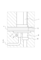
図2を再び参照すると、閉塞キャップ14は、アンカーあるいはビスなどにより地下構造物3の躯体に固定するための固定部146を有する。図4は、閉塞キャップ14が地下構造物3の躯体に固定された状態を示す図であり、閉塞キャップ14を側面から見た図である。
Referring again to FIG. 2, the blocking
図4に示すように、閉塞キャップ14は、金属製管路1に挿入される挿入部147を備える。挿入部147の外径は金属製管路1の内径とほぼ同等である。閉塞キャップ14は、挿入部147が金属製管路1に挿入された状態で、地下構造物3の躯体(側面)の内側から地下構造物3の躯体に固定される。こうすることで、閉塞キャップ14は、金属製管路1の一端1aおよび他端1bを封止することができる。通過口143およびインナー管2の周辺に機密テープ148など巻いて保護することで、気密性をより高めることができる。
As shown in FIG. 4, the
図2から図4を参照して説明したように、第1部材144および第2部材145を連結して閉塞キャップ14が形成されることで、インナー管2が金属製管路1の内部に敷設された状態で閉塞キャップ14により金属製管路1の一端1aおよび他端1bを封止することができる。
As described with reference to Figures 2 to 4, the
なお、本実施形態においては、金属製管路1の内部にインナー管2が敷設される例を用いているため、閉塞キャップ14は、通過口143を備えている。しかしながら、金属製管路1の内部にインナー管2が敷設されない場合には、閉塞キャップ14は、通過口143を備える必要はない。
In this embodiment, since an example is used in which the
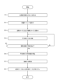
次に、本実施形態に係る防食システム10による防食方法について、図5に示すフローチャートを参照して説明する。
Next, the corrosion prevention method using the
まず、金属製管路1の内部に吸着剤を散布する、あるいは、吸引装置を使用するなどして、金属製管路1の内部の水分を除去する(ステップS11)。
First, remove moisture from inside the
次に、金属製管路1の一端1aに閉塞キャップ14aが取り付けられ、金属製管路1の他端1bに閉塞キャップ14bが取り付けられる(ステップS12)。
Next, a blocking
上述したように、閉塞キャップ14は、インナー管2が通過口143を通過した状態で、金属製管路1に取り付けられ、金属製管路1の一端1aおよび他端1bを封止する。このような状態での金属製管路1への閉塞キャップ14の取り付けは、第1部材144および第2部材145を連結することで可能である。
As described above, the blocking
例えば、第1部材144の凹部144aと第2部材145の凹部145aとにインナー管2が配置された状態で第1部材144と第2部材145とを連結することで、インナー管2が通過口143を通過した状態とすることができる。その後、金属製管路1の一端1aおよび他端1bへの閉塞キャップ14の取り付けにより、インナー管2が閉塞キャップ14aの通過口143(第1通過口)および閉塞キャップ14bの通過口143(第2通過口)を通過した状態で、金属製管路1の一端1aおよび他端1bを封止することができる。なお、閉塞キャップ14の連結口141は開放された状態である。
For example, by connecting the
次に、閉塞キャップ14aの連結口141に送気ホース11aが取り付けられ、閉塞キャップ14bの連結口141に排気ホース12aが取り付けられる(ステップS13)。
Next, the
送気ホース11aおよび排気ホース12aの取り付けが完了すると、供給装置11は、送気ホース11aを介して不活性ガスを金属製管路1の内部に供給する(ステップS14)。また、排気装置12は、排気ホース12aを介して、金属製管路1の内部の気体の排気を開始する。供給装置11により金属製管路1の内部に不活性ガスを供給し、排気装置12により金属製管路1の内部の気体を排出することで、金属製管路1の内部の空気を不活性ガスに置換することができる。
Once the installation of the
測定装置13は、金属製管路1の内部の酸素濃度または排気ホース12aから排出される気体の酸素濃度を測定する。測定装置13は、測定した酸素濃度が所定値以下であるか否かを判定する(ステップS15)。酸素濃度が所定値以下であるか否かを判定することで、金属製管路1の内部の気体の、空気から不活性ガスへの置換が進んでいるか、すなわち、金属製管路1の内部への不活性ガスの充填が完了したか否かを判定することができる。
The measuring
測定された酸素濃度が所定値以下でないと判定されると(ステップS15:No)、ステップS14の処理に戻り、供給装置11は、不活性ガスの供給を続ける。
If it is determined that the measured oxygen concentration is not equal to or lower than the predetermined value (step S15: No), the process returns to step S14, and the
測定された酸素濃度が所定値以下であると判定されると(ステップS15:Yes)、供給装置11は、不活性ガスの供給を停止する(ステップS16)。また、排気装置12は、金属製管路1の内部の気体の排気を停止する。すなわち、金属製管路1の内部への不活性ガスの充填が完了すると、不活性ガスの供給が停止される。
If it is determined that the measured oxygen concentration is equal to or lower than the predetermined value (step S15: Yes), the
金属製管路1の内部への不活性ガスの充填が完了し、不活性ガスの供給および金属製管路1の内部の気体の排気が停止すると、閉塞キャップ14aの連結口141(第1連結口)を遮断弁142(第1遮断弁)により閉塞し、閉塞キャップ14bの連結口141(第2連結口)を遮断弁142(第2遮断弁)により閉塞する(ステップS17)。こうすることで、金属製管路1の内部に不活性ガスが充填された状態とすることができる。
When filling of the interior of the
遮断弁142による連結口141の閉塞後、送気ホース11aおよび排気ホース12aが取り外される(ステップS18)
After the
このように本実施形態に係る防食システム10による防食方法は、閉塞キャップ14aにより金属製管路1の一端1aを封止し、閉塞キャップ14bにより金属製管路1の他端1bを封止するステップ(ステップS12)と、閉塞キャップ14aの連結口141に送気ホース11aを連結し、閉塞キャップ14bの連結口141に排気ホース12aを接続し、送気ホース11aを介して金属製管路1の内部に不活性ガスを供給するステップ(ステップS13,S14)と、金属製管路1の内部への不活性ガスの充填の完了後、遮断弁142により閉塞キャップ14aの連結口141を閉塞し、遮断弁142により閉塞キャップ14bの連結口141を閉塞するステップ(ステップS17)と、を含む。
The corrosion prevention method using the
金属製管路1の一端1aおよび他端1bを閉塞キャップ14で封止し、送気ホース11aを介して不活性ガスを金属製管路1の内部に供給した後、閉塞キャップ14の連結口141を閉塞することで、金属製管路1の内部を不活性ガスで充填することができる。こうすることで、本実施形態においては、金属製管路1の内部において、大気、水あるいは他の金属との接触などに起因する、様々な酸化反応による腐食の進行を抑制することができる。また、本実施形態においては、金属製管路1の内部に不活性ガスを充填することで腐食の進行を抑制するため、金属製管路1の内径を変化させることもない。そのため、金属製管路1の内部へのインナー管2の敷設性能に影響を及ぼすこともない。
The inside of the
以上の実施形態に関し、更に以下の付記を開示する。 The following notes are further provided with respect to the above embodiment.
[付記項1]
地下に埋設された金属製管路の防食方法であって、
第1連結口と、前記第1連結口を閉塞可能な第1遮断弁とを有する第1閉塞キャップにより前記金属製管路の一端を封止し、第2連結口と、前記第2連結口を閉塞可能な第2遮断弁とを有する第2閉塞キャップにより前記金属製管路の他端を封止し、
前記第1連結口に送気ホースを連結し、前記第2連結口に排気ホースを連結し、前記送気ホースを介して前記金属製管路の内部に不活性ガスを供給し、
前記金属製管路の内部への前記不活性ガスの充填の完了後、前記第1遮断弁により前記第1連結口を閉塞し、前記第2遮断弁により前記第2連結口を閉塞する、防食方法。
[Additional Note 1]
A method for preventing corrosion of a metal pipeline buried underground, comprising the steps of:
one end of the metal conduit is sealed with a first blocking cap having a first connecting port and a first shutoff valve capable of closing the first connecting port, and the other end of the metal conduit is sealed with a second blocking cap having a second connecting port and a second shutoff valve capable of closing the second connecting port;
an air supply hose is connected to the first connecting port, an exhaust hose is connected to the second connecting port, and an inert gas is supplied to the inside of the metal pipe via the air supply hose;
a first shutoff valve for closing the first connecting port and a second shutoff valve for closing the second connecting port after the inert gas has been filled into the interior of the metal pipeline;
[付記項2]
付記項1に記載の防食方法において、
前記金属製管路の内部の酸素濃度または前記排気ホースから排出される気体の酸素濃度を測定し、
前記測定された酸素濃度が所定値以下になると、前記不活性ガスの供給を停止する、防食方法。
[Additional Note 2]
In the corrosion prevention method according to
Measure the oxygen concentration inside the metal pipe or the oxygen concentration of the gas discharged from the exhaust hose;
The corrosion prevention method further comprises stopping the supply of the inert gas when the measured oxygen concentration becomes equal to or lower than a predetermined value.
[付記項3]
付記項1または2に記載の防食方法において、
前記金属製管路には、前記金属製管路の一端から挿入され、前記金属製管路の他端から露出したインナー管が敷設され、
前記第1閉塞キャップは前記インナー管が通過する第1通過口を有し、
前記第2閉塞キャップは前記インナー管が通過する第2通過口を有する、防食方法。
[Additional Note 3]
In the corrosion prevention method according to
an inner pipe is laid in the metal pipeline, the inner pipe being inserted into one end of the metal pipeline and exposed from the other end of the metal pipeline;
the first closure cap has a first passage opening through which the inner tube passes,
The second closure cap has a second passage opening through which the inner tube passes.
[付記項4]
付記項3に記載の防食方法において、
前記第1閉塞キャップおよび前記第2閉塞キャップはそれぞれ、第1部材と、前記第1部材と連結可能な第2部材とを有し、前記第1部材と前記第2部材とが連結することで、前記第1通過口および前記第2通過口が形成される、防食方法。
[Additional Note 4]
In the corrosion prevention method according to
A corrosion prevention method in which the first blocking cap and the second blocking cap each have a first member and a second member connectable to the first member, and the first passage port and the second passage port are formed by connecting the first member and the second member.
[付記項5]
地下に埋設された金属製管路の防食システムであって、
第1連結口と、前記第1連結口を閉塞可能な第1遮断弁とを有し、前記金属製管路の一端を封止する第1閉塞キャップと、
第2連結口と、前記第2連結口を閉塞可能な第2遮断弁とを有し、前記金属製管路の他端を封止する第2閉塞キャップと、
前記第1連結口に連結された送気ホースを介して、前記金属製管路の内部に不活性ガスを供給する供給装置と、
前記第2連結口に連結された排気ホースを介して、前記金属製管路の内部の気体を排気する排気装置と、を備え、
前記金属製管路の内部への前記不活性ガスの充填の完了後、前記第1遮断弁により前記第1連結口を閉塞し、前記第2遮断弁により前記第2連結口を閉塞する、防食システム。
[Additional Note 5]
A corrosion protection system for an underground buried metal pipeline, comprising:
a first blocking cap having a first connecting port and a first shutoff valve capable of closing the first connecting port and configured to seal one end of the metal pipe;
a second blocking cap having a second connecting port and a second shutoff valve capable of closing the second connecting port and sealing the other end of the metal pipe;
a supply device that supplies an inert gas to the inside of the metal pipeline through an air supply hose connected to the first connection port;
an exhaust device that exhausts gas from inside the metal pipe through an exhaust hose connected to the second connection port,
a corrosion prevention system, wherein after the inert gas has been completely filled into the interior of the metal pipeline, the first connecting port is closed by the first shutoff valve and the second connecting port is closed by the second shutoff valve.
上述の実施形態は代表的な例として説明したが、本開示の趣旨および範囲内で、多くの変更および置換ができることは当業者に明らかである。したがって、本発明は、上述の実施形態によって制限するものと解するべきではなく、請求の範囲から逸脱することなく、種々の変形または変更が可能である。例えば、実施形態の構成図に記載の複数の構成ブロックを1つに組み合わせたり、あるいは1つの構成ブロックを分割したりすることが可能である。 The above-mentioned embodiments have been described as representative examples, but it will be apparent to those skilled in the art that many modifications and substitutions can be made within the spirit and scope of the present disclosure. Therefore, the present invention should not be interpreted as being limited by the above-mentioned embodiments, and various modifications or changes are possible without departing from the scope of the claims. For example, it is possible to combine multiple configuration blocks shown in the configuration diagram of the embodiment into one, or to divide one configuration block.
1 金属製管路
2 インナー管
10 防食システム
11 供給装置
11a 送気ホース
12 排気装置
12a 排気ホース
13 測定装置
14a 閉塞キャップ(第1閉塞キャップ)
14b 閉塞キャップ(第2閉塞キャップ)
141 連結口
142 遮断弁
143 通過口
144 第1部材
144a 凹部
145 第2部材
145a 凹部
146 固定部
147 挿入部
148 機密テープ
REFERENCE SIGNS
14b Closure cap (second closure cap)
141
Claims (5)
第1連結口と、前記第1連結口を閉塞可能な第1遮断弁とを有する第1閉塞キャップにより前記金属製管路の一端を封止し、第2連結口と、前記第2連結口を閉塞可能な第2遮断弁とを有する第2閉塞キャップにより前記金属製管路の他端を封止するステップと、
前記第1連結口に送気ホースを連結し、前記第2連結口に排気ホースを連結し、前記送気ホースを介して前記金属製管路の内部に不活性ガスを供給するステップと、
前記金属製管路の内部への前記不活性ガスの充填の完了後、前記第1遮断弁により前記第1連結口を閉塞し、前記第2遮断弁により前記第2連結口を閉塞するステップと、を含む防食方法。 A method for preventing corrosion of a metal pipeline buried underground, comprising the steps of:
sealing one end of the metal conduit with a first blocking cap having a first connecting port and a first shutoff valve capable of closing the first connecting port, and sealing the other end of the metal conduit with a second blocking cap having a second connecting port and a second shutoff valve capable of closing the second connecting port;
connecting an air supply hose to the first connecting port, connecting an exhaust hose to the second connecting port, and supplying an inert gas into the inside of the metal pipeline through the air supply hose;
and after completion of filling the inside of the metal pipeline with the inert gas, closing the first connection port with the first shut-off valve and closing the second connection port with the second shut-off valve.
前記金属製管路の内部の酸素濃度または前記排気ホースから排出される気体の酸素濃度を測定するステップをさらに含み、
前記測定された酸素濃度が所定値以下になると、前記不活性ガスの供給を停止する、防食方法。 The corrosion prevention method according to claim 1,
measuring the oxygen concentration inside the metal pipe or the oxygen concentration of the gas discharged from the exhaust hose;
The corrosion prevention method further comprises stopping the supply of the inert gas when the measured oxygen concentration becomes equal to or lower than a predetermined value.
前記金属製管路には、前記金属製管路の一端から挿入され、前記金属製管路の他端から露出したインナー管が敷設され、
前記第1閉塞キャップは前記インナー管が通過する第1通過口を有し、
前記第2閉塞キャップは前記インナー管が通過する第2通過口を有する、防食方法。 The corrosion prevention method according to claim 1,
an inner pipe is laid in the metal pipeline, the inner pipe being inserted into one end of the metal pipeline and exposed from the other end of the metal pipeline;
the first closure cap has a first passage opening through which the inner tube passes,
The second closure cap has a second passage opening through which the inner tube passes.
前記第1閉塞キャップおよび前記第2閉塞キャップはそれぞれ、第1部材と、前記第1部材と連結可能な第2部材とを有し、前記第1部材と前記第2部材とが連結することで、前記第1通過口および前記第2通過口が形成される、防食方法。 The corrosion prevention method according to claim 3,
A corrosion prevention method in which the first blocking cap and the second blocking cap each have a first member and a second member connectable to the first member, and the first passage port and the second passage port are formed by connecting the first member and the second member.
第1連結口と、前記第1連結口を閉塞可能な第1遮断弁とを有し、前記金属製管路の一端を封止する第1閉塞キャップと、
第2連結口と、前記第2連結口を閉塞可能な第2遮断弁とを有し、前記金属製管路の他端を封止する第2閉塞キャップと、
前記第1連結口に連結された送気ホースを介して、前記金属製管路の内部に不活性ガスを供給する供給装置と、
前記第2連結口に連結された排気ホースを介して、前記金属製管路の内部の気体を排気する排気装置と、を備え、
前記金属製管路の内部への前記不活性ガスの充填の完了後、前記第1遮断弁により前記第1連結口が閉塞され、前記第2遮断弁により前記第2連結口が閉塞される、防食システム。 A corrosion protection system for an underground buried metal pipeline, comprising:
a first blocking cap having a first connecting port and a first shutoff valve capable of closing the first connecting port and configured to seal one end of the metal pipe;
a second blocking cap having a second connecting port and a second shutoff valve capable of closing the second connecting port and sealing the other end of the metal pipe;
a supply device that supplies an inert gas to the inside of the metal pipeline through an air supply hose connected to the first connection port;
an exhaust device that exhausts gas from inside the metal pipe through an exhaust hose connected to the second connection port,
a corrosion prevention system, wherein after completion of filling the inside of the metal pipeline with the inert gas, the first connection port is closed by the first shutoff valve and the second connection port is closed by the second shutoff valve.
Priority Applications (1)
| Application Number | Priority Date | Filing Date | Title |
|---|---|---|---|
| PCT/JP2023/021059 WO2024252532A1 (en) | 2023-06-06 | 2023-06-06 | Corrosion prevention method and corrosion prevention system |
Applications Claiming Priority (1)
| Application Number | Priority Date | Filing Date | Title |
|---|---|---|---|
| PCT/JP2023/021059 WO2024252532A1 (en) | 2023-06-06 | 2023-06-06 | Corrosion prevention method and corrosion prevention system |
Publications (1)
| Publication Number | Publication Date |
|---|---|
| WO2024252532A1 true WO2024252532A1 (en) | 2024-12-12 |
Family
ID=93795516
Family Applications (1)
| Application Number | Title | Priority Date | Filing Date |
|---|---|---|---|
| PCT/JP2023/021059 Ceased WO2024252532A1 (en) | 2023-06-06 | 2023-06-06 | Corrosion prevention method and corrosion prevention system |
Country Status (1)
| Country | Link |
|---|---|
| WO (1) | WO2024252532A1 (en) |
Citations (6)
| Publication number | Priority date | Publication date | Assignee | Title |
|---|---|---|---|---|
| JPS499359B1 (en) * | 1966-08-10 | 1974-03-04 | ||
| JPH09310793A (en) * | 1996-05-23 | 1997-12-02 | Osaka Gas Co Ltd | Pipe end cap |
| JP2000310391A (en) * | 1999-04-28 | 2000-11-07 | Nkk Corp | Bellows type expansion joint |
| JP2004340328A (en) * | 2003-05-19 | 2004-12-02 | Japan Gas Association | Air purge device |
| JP2009257492A (en) * | 2008-04-17 | 2009-11-05 | Nippon Steel Corp | Repair method and repair structure of gas piping |
| US20220112977A1 (en) * | 2020-10-13 | 2022-04-14 | General Air Products, Inc. | Corrosion risk reduction apparatus, corrosion risk reduction detection device and corrosion risk reduction systems and methods |
-
2023
- 2023-06-06 WO PCT/JP2023/021059 patent/WO2024252532A1/en not_active Ceased
Patent Citations (6)
| Publication number | Priority date | Publication date | Assignee | Title |
|---|---|---|---|---|
| JPS499359B1 (en) * | 1966-08-10 | 1974-03-04 | ||
| JPH09310793A (en) * | 1996-05-23 | 1997-12-02 | Osaka Gas Co Ltd | Pipe end cap |
| JP2000310391A (en) * | 1999-04-28 | 2000-11-07 | Nkk Corp | Bellows type expansion joint |
| JP2004340328A (en) * | 2003-05-19 | 2004-12-02 | Japan Gas Association | Air purge device |
| JP2009257492A (en) * | 2008-04-17 | 2009-11-05 | Nippon Steel Corp | Repair method and repair structure of gas piping |
| US20220112977A1 (en) * | 2020-10-13 | 2022-04-14 | General Air Products, Inc. | Corrosion risk reduction apparatus, corrosion risk reduction detection device and corrosion risk reduction systems and methods |
Similar Documents
| Publication | Publication Date | Title |
|---|---|---|
| US10718463B2 (en) | System and method for protecting one or more pipes against corrosion and corrosion-protected pipe | |
| CN107339524A (en) | A kind of new pipe fitting and its pipe-line system | |
| CA2354226A1 (en) | Robotic apparatus and method for non-destructive maintenance of intersecting conduits | |
| BR9909078A (en) | System and device to internally coat a gasket or other discontinuity in a pipeline of live gas | |
| Krasovskaya et al. | Designing trenchless technologies in oil and gas engineering | |
| WO2024252532A1 (en) | Corrosion prevention method and corrosion prevention system | |
| KR100696318B1 (en) | Pipe Binding Device for Pipeline | |
| US12510203B2 (en) | Methods and systems for sealing a service pipe | |
| US20210285590A1 (en) | Methods, systems, and apparatus for providing access for telecommunication cables in utility piping | |
| CN110486532B (en) | Trenchless pipeline repairing construction process | |
| JP7171036B2 (en) | Methods for reducing leaks or risk of leaks in pipe systems | |
| US6505783B1 (en) | Method for rehabilitating low pressure service mains connections | |
| CN205578947U (en) | Anticorrosive device of repaired mouth of pipeline butt joint weld bond | |
| CN206875017U (en) | A kind of emergent closure shunting device of petroleum pipeline | |
| JPH03249493A (en) | Corrosion preventing structure for underground pipe line and method of building thereof | |
| JP6802563B2 (en) | Fixing tool for rehabilitation pipe and fixing tool for rehabilitation pipe | |
| WO2024252533A1 (en) | Laying method and laying system | |
| CN120819709A (en) | A construction method for steel-wrapped joints of inserted pipes in oil fields | |
| US20230021427A1 (en) | Casing system and method for pipeline reinforcement and repair | |
| Bylin et al. | New measurement data has implications for quantifying natural gas losses from cast iron distribution mains | |
| JP4786227B2 (en) | Lining method for existing pipelines | |
| JPH0413485B2 (en) | ||
| WO2025099915A1 (en) | Pipeline and method for inspecting pipeline | |
| Konno | Development of the “Gray-Buster-Advance Lining” method for renovation of gray cast-iron pipes | |
| Thomas | 2-Layer Polyethylene Plant Applied Mainline Coating for Use in Water and Wastewater Pipeline Applications |
Legal Events
| Date | Code | Title | Description |
|---|---|---|---|
| 121 | Ep: the epo has been informed by wipo that ep was designated in this application |
Ref document number: 23940637 Country of ref document: EP Kind code of ref document: A1 |
|
| NENP | Non-entry into the national phase |
Ref country code: DE |