WO2024252533A1 - Laying method and laying system - Google Patents
Laying method and laying system Download PDFInfo
- Publication number
- WO2024252533A1 WO2024252533A1 PCT/JP2023/021060 JP2023021060W WO2024252533A1 WO 2024252533 A1 WO2024252533 A1 WO 2024252533A1 JP 2023021060 W JP2023021060 W JP 2023021060W WO 2024252533 A1 WO2024252533 A1 WO 2024252533A1
- Authority
- WO
- WIPO (PCT)
- Prior art keywords
- pipeline
- fixing jig
- injection
- pipe
- injection port
- Prior art date
- Legal status (The legal status is an assumption and is not a legal conclusion. Google has not performed a legal analysis and makes no representation as to the accuracy of the status listed.)
- Ceased
Links
Images


Classifications
-
- E—FIXED CONSTRUCTIONS
- E03—WATER SUPPLY; SEWERAGE
- E03F—SEWERS; CESSPOOLS
- E03F3/00—Sewer pipe-line systems
- E03F3/04—Pipes or fittings specially adapted to sewers
Definitions
- This disclosure relates to an installation method and system.
- Non-Patent Document 1 In order to utilize hydrogen energy to achieve carbon neutrality, hydrogen pipelines for transporting hydrogen are being installed (see Non-Patent Document 1). Conventionally, when hydrogen pipelines are installed underground, the pipelines are buried directly in the ground. By burying the pipelines directly in the ground, the load in the soil acts as a restraining force, suppressing deformation due to elongation of the buried pipelines.
- inner pipes for hydrogen pipelines and the like may also be laid inside existing pipelines that are already buried underground, such as communication pipelines.
- flexible pipes are used as the inner pipes to accommodate the unevenness and curves of the existing pipeline.
- the flexible pipe is fixed in place with metal fittings or the like to restrict its extension.
- the purpose of this disclosure is to provide an installation method and installation system that can suppress deformation of the second pipeline installed inside the first pipeline.
- the laying method is a laying method for laying a second pipeline inside a first pipeline buried underground, and includes the steps of: fixing the second pipeline and sealing one end of the first pipeline with a first fixing jig having an injection port and a shutoff valve capable of closing the injection port, while the second pipeline is inserted into one end of the first pipeline and exposed from the other end of the first pipeline, and fixing the second pipeline and sealing the other end of the first pipeline with a second fixing jig; injecting a filler that is inactive with respect to the first pipeline and the second pipeline from a third pipeline inserted into the injection port between the first pipeline and the second pipeline; and, after the filling of the filler between the first pipeline and the second pipeline is completed, pulling out the third pipeline from the first pipeline and closing the injection port with the shutoff valve.
- the installation system is an installation system for laying a second pipeline inside a first pipeline buried underground, and includes a traction device that traction-exposes the second pipeline inserted from one end of the first pipeline from the other end of the first pipeline, an injection port, and a shutoff valve that can shut off and open the injection port, and fixes the second pipeline and seals one end of the first pipeline when the second pipeline is inserted from one end of the first pipeline.
- a first fixing jig for fixing the second pipeline in a state in which the second pipeline is exposed from the other end of the first pipeline and sealing the other end of the first pipeline; an injection device for injecting a filler that is inactive with respect to the first pipeline and the second pipeline from a third pipeline inserted into the injection port between the first pipeline and the second pipeline; and a winding device for pulling out the third pipeline from the first pipeline after the filling of the filler between the first pipeline and the second pipeline is completed.
- the installation method and system disclosed herein can suppress deformation of the second pipeline installed inside the first pipeline.
- FIG. 1 is a diagram illustrating a configuration example of an installation system according to an embodiment of the present disclosure.
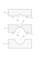
- FIG. 2 is a front view of the fixing jig 15 shown in FIG. 2 is a diagram showing members constituting the fixing jig 15 shown in FIG. 1 before being connected together.
- FIG. 2 is a diagram showing a state in which the fixing jig 15 shown in FIG. 1 is fixed to one end of an existing pipeline.
- FIG. 2 is a front view of the fixing jig 16 shown in FIG. 2 is a diagram showing members constituting the fixing jig 16 shown in FIG. 1 before being connected together.
- 2 is a flowchart for explaining a laying method using the laying system shown in FIG. 1 .
- FIG. 1 is a diagram showing an example of the configuration of an installation system 10 according to an embodiment of the present disclosure.
- the installation system 10 according to this embodiment is for installing an inner pipeline as a second pipeline inside an existing pipeline 1 as a first pipeline, such as a communication pipeline, buried underground.
- the inner pipeline is assumed to be a flexible pipe 2 having flexibility.
- the existing pipeline 1 is provided so as to connect underground structures 4 installed underground, such as manholes, handholes, or tunnels, for example, as shown in FIG. 1.
- the installation system 10 includes a sending device 11, a towing device 12, a winding device 13, an injection device 14, and fixing devices 15 and 16.
- the sending device 11, the towing device 12, the winding device 13, and the injection device 14 are installed, for example, on the ground.
- the delivery device 11 has the function of storing the flexible tube 2.
- the delivery device 11 can deliver the stored flexible tube 2 in accordance with the towing of the flexible tube 2 by the towing device 12 described below.
- the towing device 12 is equipped with a towing jig 12a to which the flexible pipe 2 can be fixed, and can tow the flexible pipe 2 fixed to the towing jig 12a at a speed specified by an operator or the like.
- the towing device 12 tows the flexible pipe 2 inserted from one end 1a of the existing pipeline 1 from the other end 1b of the existing pipeline 1, and exposes it from the other end 1b of the existing pipeline 1.
- the towing device 12 can tow the injection pipe 3 together with the flexible pipe 2.
- the winding device 13 has the function of storing the injection tube 3 as the third pipeline.
- the winding device 13 can feed out the stored injection tube 3 in accordance with the towing device 12 pulling the flexible pipe 2 to which the injection tube 3 is fixed.
- the winding device 13 can also wind up the injection tube 3 pulled out by the towing device 12 at a speed specified by an operator or the like.
- the winding device 13 can pull out the injection tube 3 from the existing pipeline 1 after the injection device 14, described below, has completed filling the space between the existing pipeline 1 and the flexible pipe 2 with the filling material.
- the injection device 14 has a function of containing a filler that is inactive to the existing pipeline 1 and the flexible pipe 2.
- the filler is not particularly limited as long as it is inactive to the existing pipeline 1 and the flexible pipe 2 (i.e., it does not cause corrosion of the existing pipeline 1 and the flexible pipe 2) and can fill the gap between the existing pipeline 1 and the flexible pipe 2.
- the filler is, for example, dry sand. In the following description, the filler is dry sand.
- the injection device 14 injects the dry sand, which is the filler to be contained, from the injection pipe 3 between the existing pipeline 1 and the flexible pipe 2.
- the injection device 14 can discharge the contained dry sand at a speed specified by an operator or the like.
- the injection device 14 may inject at least one of an oxygen scavenger and a desiccant together with the dry sand.
- an oxygen scavenger and a desiccant together with the dry sand.
- Figure 2 is a front view of the fixing jig 15.
- the fixture 15 has a passage port 151, an injection port 152, and a shutoff valve 153.
- the passage port 151 which serves as the first passage port, allows the flexible pipe 2 to pass through and can fix the flexible pipe 2 that has passed through the passage port 151.
- a half fixing plate 151a is provided on the inner periphery of the passage port 151.
- the position of the fixing plate 151a can be adjusted in the radial direction of the passage port 151 by the adjustment screw 151b.
- the flexible pipe 2 that has passed through the passage port 151 can be fixed by adjusting the position of the fixing plate 151a by the adjustment screw 151b to match the thickness of the flexible pipe 2.
- the injection port 152 allows the injection tube 3 to pass through.
- the shutoff valve 153 can close and open the injection port 152.
- the fixing jig 15 includes a first member 154, a second member 155 connectable to the first member 154, and a third member 156 connectable to the second member 155. As shown in FIG. 3, the first member 154, the second member 155, and the third member 156 are provided separately, and the fixing jig 15 is formed by connecting these members. Note that the fixing plate 151a, the adjustment screw 151b, and the shutoff valve 153 are omitted from FIG. 3.
- the first member 154 is a rectangular member in a plan view, and has a semicircular recess 154a on one side.
- the second member 155 is a rectangular member in a plan view, with a semicircular recess 155a on one side and a semicircular recess 155b on the other side opposite the first side.
- the first member 154 and the second member 155 are connected, for example, by a screw 155c, so that the side on which the recess 154a is provided is in contact with the side on which the recess 155a is provided.
- the passage opening 151 is formed by connecting the first member 154 and the second member 155.
- the third member 156 is a rectangular member in a plan view, and has a semicircular recess 156a on one side.
- the second member 155 and the third member 156 are connected, for example, by a screw 156b, so that the side on which the recess 155b is provided is in contact with the side on which the recess 156a is provided.
- the injection port 152 is formed by connecting the second member 155 and the third member 156.
- the fixing jig 15 has a fixing portion 157 for fixing to the frame of the underground structure 4 with an anchor or a screw.
- FIG. 4 shows the state in which the fixing jig 15 is fixed to the frame of the underground structure 4.
- the fixing jig 15 has an insertion portion 158 that is inserted into the existing pipeline 1 from one end 1a of the existing pipeline 1.
- the outer diameter of the insertion portion 158 is approximately equal to the inner diameter of the existing pipeline 1.
- the fixing jig 15 With the insertion portion 158 inserted into the existing pipeline 1, the fixing jig 15 is fixed to the structure of the underground structure 4 from the inside of the structure (side surface) of the underground structure 4. In this way, the fixing jig 15 can seal one end 1a of the existing pipeline 1. Airtightness can be further improved by wrapping security tape 159 or the like around the passage opening 151 and the flexible pipe 2 for protection.
- the fixing jig 15 is formed by connecting the first member 154, the second member 155, and the third member 156, so that after the flexible pipe 2 and the injection pipe 3 are inserted into the existing pipeline 1, the fixing jig 15 can seal one end 1a of the existing pipeline 1 with the flexible pipe 2 passing through the passage port 151 and the injection pipe 3 passing through the injection port 152.
- the fixing jig 16 as the second fixing jig can fix the flexible pipe 2 in a state where the flexible pipe 2 is exposed from the other end 1b of the existing pipeline 1. As shown in FIG. 1, the fixing jig 16 is fixed to the body of the underground structure 4 at the other end 1b of the existing pipeline 1, and seals the other end 1b of the existing pipeline 1.
- Figure 5 is a front view of the fixing jig 16.
- the fixing jig 16 has a passage opening 161.
- the passage opening 161 allows the flexible pipe 2 to pass through and can also fix the flexible pipe 2 that has passed through the passage opening 161.
- a half fixing plate 161a is provided on the inner periphery of the passage opening 161.
- the position of the fixing plate 161a can be adjusted in the radial direction of the passage opening 161 by the adjustment screw 161b.
- the flexible pipe 2 that has passed through the passage opening 161 can be fixed by adjusting the position of the fixing plate 161a by the adjustment screw 161b to match the thickness of the flexible pipe 2.
- the fixing jig 16 includes a fourth member 164 and a fifth member 165 that can be connected to the fourth member 164. As shown in FIG. 6, the fourth member 164 and the fifth member 165 are provided separately, and are connected to form the fixing jig 16.
- the fourth member 164 is a rectangular member in a plan view, and has a semicircular recess 164a on one side.
- the fifth member 165 is a rectangular member in a plan view, and has a semicircular recess 165a on one side.
- the fourth member 164 and the fifth member 165 are connected, for example, by a screw 165c, so that the side on which the recess 164a is provided and the side on which the recess 165a is provided are in contact with each other.
- the passage opening 161 is formed by connecting the fourth member 164 and the fifth member 165.
- the fixing jig 16 has a fixing portion 167 for fixing to the frame of the underground structure 4 with an anchor or a screw.
- the method of fixing to the underground structure 4 is the same as for the fixing jig 15, so a description thereof will be omitted.
- a towing jig 12a is attached to the tip of a flexible pipe 2 inserted from one end 1a of the existing pipeline 1.
- An injection pipe 3 is tied to the flexible pipe 2 near its tip. With the injection pipe 3 tied to the flexible pipe 2, the flexible pipe 2 is towed by the towing device 12, causing the flexible pipe 2 to be sent out from the sending device 11 and the injection pipe 3 to be sent out from the winding device 13, and the flexible pipe 2 and the injection pipe 3 to be pulled into the existing pipeline 1.
- the towing by the towing device 12 is stopped.
- the binding between the flexible pipe 2 and the injection pipe 3 is released.
- the winding device 13 winds up the injection pipe 3 so that the tip of the injection pipe 3 is located inside the existing pipeline 1.
- the flexible pipe 2 is exposed from the other end 1b of the existing pipeline 1, and the injection pipe 3 can be laid in a state where it is placed in the existing pipeline 1. It is preferable that the injection pipe 3 is positioned so that the tip of the injection pipe 3 is located near the other end 1b of the existing pipeline 1.
- fixing jigs 15, 16 are attached to the existing pipeline 1 (step S12). Specifically, the fixing jig 15 fixes the flexible pipe 2 and seals one end 1a of the existing pipeline 1. The fixing jig 16 fixes the flexible pipe 2 and seals the other end 1b of the existing pipeline 1.
- the fixing jig 15 is attached to the existing pipeline 1 with the flexible pipe 2 passing through the passage port 151 and the injection pipe 3 passing through the injection port 152, and seals one end 1a of the existing pipeline 1.
- the fixing jig 15 can be attached to the existing pipeline 1 in this state by sequentially connecting the first member 154, the second member 155, and the third member 156.
- the flexible tube 2 can be placed in a state of passing through the passage port 151.
- the second member 155 and the third member 156 with the injection tube 3 placed in the recess 155b of the second member 155 and the recess 156a of the third member 156, the injection tube 3 can be placed in a state of passing through the injection port 152.
- the fixing jig 15 to one end 1a of the existing pipeline 1 and adjusting the position of the fixing plate 151a with the adjustment screw 151b, the one end 1a of the existing pipeline 1 can be sealed with the flexible pipe 2 fixed by the fixing jig 15.
- the fixing jig 16 is attached to the existing pipeline 1 with the flexible pipe 2 passing through the passage opening 161, and seals the other end 1b of the existing pipeline 1.
- the fixing jig 16 can be attached to the existing pipeline 1 in this state by connecting the fourth member 164 and the fifth member 165.
- the flexible tube 2 can be placed in a state of passing through the passage opening 161.
- the injection device 14 starts injecting dry sand from the injection pipe 3 inserted into the injection port 152 into the space between the existing pipeline 1 and the flexible pipe 2 (step S13).
- the winding device 13 starts winding the injection pipe 3 at a constant speed (step S14).
- the dry sand is injected sequentially toward one end 1a of the existing pipeline 1.
- the speed at which the injection pipe 3 is wound is set so that the space between the existing pipeline 1 and the flexible pipe 2 (between the inner diameter of the existing pipeline 1 and the outer diameter of the flexible pipe 2) is sufficiently filled with dry sand (at least to the extent that the flexible pipe 2 is buried in dry sand).
- the injection device 14 stops injecting the dry sand (step S15).
- step S16 After the injection of the dry sand is stopped, the injection port 152 is closed by the shutoff valve 153 of the fixing jig 15 (step S16). This seals the existing pipeline 1 with the dry sand filled between the existing pipeline 1 and the flexible pipe 2.
- the laying method using the laying system 10 thus includes the steps of: fixing the flexible pipe 2 with the fixing jig 15 and sealing one end 1a of the existing pipeline 1 while the flexible pipe 2 is inserted into one end 1a and exposed from the other end 1b of the existing pipeline 1; fixing the flexible pipe 2 with the fixing jig 15 and sealing the other end 1b of the existing pipeline with the fixing jig 16 (steps S11 and S12); injecting a filler (e.g., dry sand) that is inactive to the existing pipeline 1 and the flexible pipe 2 between the existing pipeline 1 and the flexible pipe 2 from the injection pipe 3 inserted into the injection port 152 (steps S13 and S14); and, after the filling of the filler between the existing pipeline and the flexible pipe 2 is completed, pulling out the injection pipe 3 from the existing pipeline 1 and closing the injection port 152 with the shutoff valve 153 (steps S15 and S16).
- a filler e.g., dry sand
- the second pipeline By filling the gap between the first pipeline (existing pipeline 1) and the second pipeline (flexible pipe 2), the second pipeline is restrained by the reaction force of the filled pipeline, and deformation such as extension and bending of the second pipeline inside the first pipeline can be suppressed. Therefore, deformation of the second pipeline laid inside the first pipeline can be suppressed.
- the existing pipeline 1 already buried underground is used to lay the second pipeline, which reduces the scope of construction such as cutting, making it possible to lay an economical hydrogen pipeline.
- the filler is filled between the first pipeline and the second pipeline, even if gas (e.g., hydrogen) leaks from the second pipeline, the space in which the leaked gas stagnates between the first pipeline and the second pipeline is reduced, so that the stagnation of the leaked gas can be suppressed.
- gas e.g., hydrogen
- a method for laying a second pipeline inside a first pipeline buried underground comprising the steps of: a first fixing jig having an injection port and a shutoff valve capable of closing the injection port, the second pipe is fixed and the first pipe is sealed at one end thereof, and a second fixing jig is used to fix the second pipe and seal the other end thereof, with the second pipe being inserted into the first pipe and exposed from the other end thereof; injecting a filler that is inactive with respect to the first pipeline and the second pipeline from a third pipeline inserted into the injection port between the first pipeline and the second pipeline; the third pipeline is pulled out from the first pipeline, and the injection port is closed by the shutoff valve after the filling of the filler between the first pipeline and the second pipeline is completed.
- the installation method further comprises injecting at least one of an oxygen scavenger and a desiccant between the first pipeline and the second pipeline.
- the first fixing jig has a first member, a second member connectable to the first member, and a third member connectable to the second member, the first member and the second member being connected to each other to form a first passage port through which the first pipeline passes, and the second member and the third member being connected to each other to form the injection port
- the second fixing jig has a fourth member and a fifth member connectable to the fourth member, and a second passage port through which the first pipeline passes is formed by connecting the fourth member and the fifth member; inserting the second pipeline and the third pipeline from one end of the first pipeline, exposing the second pipeline from the other end of the first pipeline, and arranging the third pipeline inside the first pipeline; connecting the first member and the second member with the second pipeline passing through the first passage port, connecting the second member and the third member with the third pipeline passing through the injection port, and connecting the fourth member and the fifth member with the second pipeline passing through the second passage port.
- a system for laying a second pipeline inside a first pipeline buried underground comprising: a pulling device that pulls the second pipeline inserted from one end of the first pipeline from the other end side of the first pipeline to expose the second pipeline from the other end of the first pipeline; a first fixing jig having an injection port and a shutoff valve capable of shutting off and opening the injection port, the first fixing jig fixing the second pipe and sealing the one end of the first pipe in a state in which the second pipe is inserted into the one end of the first pipe; a second fixing jig that fixes the second pipeline and seals the other end of the first pipeline in a state in which the second pipeline is exposed from the other end of the first pipeline; an injection device that injects a filler that is inactive with respect to the first pipeline and the second pipeline from a third pipeline inserted into the injection port between the first pipeline and the second pipeline; and a winding device that pulls out the third pipeline from the first pipeline after the filling of the filler between the first
Landscapes
- Health & Medical Sciences (AREA)
- Life Sciences & Earth Sciences (AREA)
- Engineering & Computer Science (AREA)
- Hydrology & Water Resources (AREA)
- Public Health (AREA)
- Water Supply & Treatment (AREA)
- Underground Structures, Protecting, Testing And Restoring Foundations (AREA)
Abstract
Description
本開示は、敷設方法および敷設システムに関する。 This disclosure relates to an installation method and system.
カーボンニュートラルの実現に向けた水素エネルギーの活用のために、水素を運搬するための水素パイプラインの設置が進められている(非特許文献1参照)。従来、水素パイプラインとなる管路を地下に設置する場合、管路は地中に直接埋設されていた。管路を地中に直接埋設することで、土中の荷重が拘束力となり、埋設した管路の伸長などによる変形が抑制される。 In order to utilize hydrogen energy to achieve carbon neutrality, hydrogen pipelines for transporting hydrogen are being installed (see Non-Patent Document 1). Conventionally, when hydrogen pipelines are installed underground, the pipelines are buried directly in the ground. By burying the pipelines directly in the ground, the load in the soil acts as a restraining force, suppressing deformation due to elongation of the buried pipelines.
一方で、通信用管路などの地下に既に埋設されている既設管路の内部に水素パイプラインなどのインナー管を敷設することもある。この場合、既設管路の不陸および曲線に対応するため、インナー管として、可撓性を有するフレキシブル管が使用される。既設管路の内部にフレキシブル管を敷設する場合、フレキシブル管の伸長を拘束するために、金物などによりフレキシブル管が固定される。 On the other hand, inner pipes for hydrogen pipelines and the like may also be laid inside existing pipelines that are already buried underground, such as communication pipelines. In these cases, flexible pipes are used as the inner pipes to accommodate the unevenness and curves of the existing pipeline. When laying a flexible pipe inside an existing pipeline, the flexible pipe is fixed in place with metal fittings or the like to restrict its extension.
さや管となる既設管路のサイズなどによっては、既設管路の内部にフレキシブル管を固定する金物を設置するスペースがない、あるいは、金物を設置するのが困難である場合がある。このような場合、フレキシブル管を固定することができず、フレキシブル管の伸長により、既設管路内でのフレキシブル管の座屈あるいは破損などを招いてしまう可能性がある。 Depending on the size of the existing pipeline that will become the sheath, there may be no space inside the existing pipeline to install hardware to secure the flexible pipe, or it may be difficult to install the hardware. In such cases, the flexible pipe cannot be secured in place, and the stretching of the flexible pipe may lead to buckling or breakage of the flexible pipe inside the existing pipeline.
また、水素パイプラインを土中に直接埋設する場合、管路の破損などにより水素が漏洩しても、漏洩した水素は土中などに拡散される。一方、既設管路の内部にフレキシブル管を敷設する場合、フレキシブル管の座屈あるいは腐食などによりフレキシブル管が破損すると、既設管路とフレキシブル管との間に可燃性の水素が漏洩し、滞留するおそれがある。 In addition, if a hydrogen pipeline is buried directly underground, even if hydrogen leaks due to damage to the pipeline, the leaked hydrogen will be dispersed into the soil. On the other hand, if a flexible pipe is laid inside an existing pipeline, and the flexible pipe is damaged due to buckling or corrosion, there is a risk that flammable hydrogen will leak and become trapped between the existing pipeline and the flexible pipe.
そのため、既設管路の内部にフレキシブル管を敷設する場合に、フレキシブル管の伸長、屈曲などの変形を抑制する技術が求められている。 Therefore, there is a demand for technology that can suppress deformation such as stretching and bending of flexible pipes when laying them inside existing pipelines.
上記のような問題点に鑑みてなされた本開示の目的は、第1管路の内部に敷設される第2管路の変形を抑制することができる敷設方法および敷設システムを提供することにある。 The purpose of this disclosure, made in consideration of the above problems, is to provide an installation method and installation system that can suppress deformation of the second pipeline installed inside the first pipeline.
上記課題を解決するため、本開示に係る敷設方法は、地下に埋設された第1管路の内部に第2管路を敷設する敷設方法であって、前記第2管路が前記第1管路の一端から挿入され、前記第1管路の他端から露出した状態で、注入口と、前記注入口を閉塞可能な遮断弁とを有する第1固定治具により、前記第2管路を固定するとともに前記第1管路の一端を封止し、第2固定治具により、前記第2管路を固定するとともに前記第1管路の他端を封止するステップと、前記注入口に挿入された第3管路から、前記第1管路と前記第2管路との間に、前記第1管路および前記第2管路に対して不活性な充填体を注入するステップと、前記第1管路と前記第2管路との間への前記充填体の充填の完了後、前記第3管路を前記第1管路から引き抜き、前記遮断弁により前記注入口を閉塞するステップと、を含む。 In order to solve the above problem, the laying method according to the present disclosure is a laying method for laying a second pipeline inside a first pipeline buried underground, and includes the steps of: fixing the second pipeline and sealing one end of the first pipeline with a first fixing jig having an injection port and a shutoff valve capable of closing the injection port, while the second pipeline is inserted into one end of the first pipeline and exposed from the other end of the first pipeline, and fixing the second pipeline and sealing the other end of the first pipeline with a second fixing jig; injecting a filler that is inactive with respect to the first pipeline and the second pipeline from a third pipeline inserted into the injection port between the first pipeline and the second pipeline; and, after the filling of the filler between the first pipeline and the second pipeline is completed, pulling out the third pipeline from the first pipeline and closing the injection port with the shutoff valve.
上記課題を解決するため、本開示に係る敷設システムは、地下に埋設された第1管路の内部に第2管路を敷設する敷設システムであって、前記第1管路の一端から挿入された前記第2管路を前記第1管路の他端側から牽引して、前記第1管路の他端から露出させる牽引装置と、注入口と、前記注入口を遮断・開放可能な遮断弁とを有し、前記第2管路が前記第1管路の一端から挿入された状態で、前記第2管路を固定するとともに前記第1管路の一端を封止する第1固定治具と、前記第2管路が前記第1管路の他端から露出した状態で、前記第2管路を固定するとともに前期第1管路の他端を封止する第2固定治具と、前記注入口に挿入された第3管路から、前記第1管路と前記第2管路との間に、前記第1管路および前記第2管路に対して不活性な充填体を注入する注入装置と、前記第1管路と前記第2管路との間への前記充填体の充填の完了後、前記第3管路を前記第1管路から引き抜く巻取装置と、を備える。 In order to solve the above problem, the installation system according to the present disclosure is an installation system for laying a second pipeline inside a first pipeline buried underground, and includes a traction device that traction-exposes the second pipeline inserted from one end of the first pipeline from the other end of the first pipeline, an injection port, and a shutoff valve that can shut off and open the injection port, and fixes the second pipeline and seals one end of the first pipeline when the second pipeline is inserted from one end of the first pipeline. a first fixing jig for fixing the second pipeline in a state in which the second pipeline is exposed from the other end of the first pipeline and sealing the other end of the first pipeline; an injection device for injecting a filler that is inactive with respect to the first pipeline and the second pipeline from a third pipeline inserted into the injection port between the first pipeline and the second pipeline; and a winding device for pulling out the third pipeline from the first pipeline after the filling of the filler between the first pipeline and the second pipeline is completed.
本開示に係る敷設方法および敷設システムによれば、第1管路の内部に敷設される第2管路の変形を抑制することができる。 The installation method and system disclosed herein can suppress deformation of the second pipeline installed inside the first pipeline.
以下、本開示の実施の形態について図面を参照して説明する。 The following describes an embodiment of the present disclosure with reference to the drawings.
図1は、本開示の一実施形態に係る敷設システム10の構成例を示す図である。本実施形態に係る敷設システム10は、通信管路などの地下に埋設された、第1管路としての既設管路1の内部に、第2管路としてのインナー管路を敷設するためのものである。以下では、インナー管路は、可撓性を有するフレキシブル管2であるとする。既設管路1は、例えば、図1に示すように、マンホール、ハンドホールあるいはとう道などの、地下に設置された地下構造物4同士を連通するように設けられている。
FIG. 1 is a diagram showing an example of the configuration of an
図1に示すように、本実施形態に係る敷設システム10は、送出し装置11と、牽引装置12と、巻取装置13と、注入装置14と、固定治具15,16とを備える。送出し装置11、牽引装置12、巻取装置13および注入装置14は、例えば、地上に設置される。
As shown in FIG. 1, the
送出し装置11は、フレキシブル管2を収納する機能を備える。送出し装置11は、後述する牽引装置12によるフレキシブル管2の牽引に合わせて、収納しているフレキシブル管2を送り出すことができる。
The
牽引装置12は、フレキシブル管2を固定可能な牽引治具12aを備えており、牽引治具12aに固定されたフレキシブル管2を、作業者などにより指定された速度で牽引することができる。本実施形態においては、図1に示すように、牽引装置12は、既設管路1の一端1aから挿入されたフレキシブル管2を、既設管路1の他端1b側から牽引して、既設管路1の他端1bから露出させる。なお、フレキシブル管2の先端付近に後述する注入管3を固定することで、牽引装置12は、フレキシブル管2とともに注入管3を牽引することができる。
The
巻取装置13は、第3管路としての注入管3を収納する機能を備える。巻取装置13は、牽引装置12による、注入管3が固定されたフレキシブル管2の牽引に合わせて、収納している注入管3を送り出すことができる。また、巻取装置13は、巻取装置12による牽引により引き出された注入管3を、作業者などにより指定された速度で巻き取ることができる。巻取装置13は、後述する注入装置14による既設管路1とフレキシブル管2との間への充填体の充填の完了後、注入管3を既設管路1から引き抜くことができる。
The
注入装置14は、既設管路1およびフレキシブル管2に対して不活性な充填体を収容する機能を備える。充填体は、既設管路1およびフレキシブル管2に対して不活性であり(すなわち、既設管路1およびフレキシブル管2の腐食などを生じさせない)、かつ、既設管路1とフレキシブル管2との隙間を埋めることができるものであれば、特に限定されない。充填体は、例えば、乾燥砂である。以下では、充填体は乾燥砂であるとして説明する。注入装置14は、注入管3から、既設管路1とフレキシブル管2との間に、収容する、充填体である乾燥砂を注入する。注入装置14は、収容する乾燥砂を、作業者などにより指定された速度で排出することができる。注入装置14は、乾燥砂とともに、脱酸素剤および乾燥剤の少なくとも一方を注入してもよい。既設管路1が金属製の管路である場合、乾燥砂とともに、脱酸素剤および乾燥剤の少なくとも一方を注入することで、既設管路1における大気、水あるいは他の金属との接触に起因する様々な酸化反応による腐食の進行を抑制することができる。
The
第1固定治具としての固定治具15は、フレキシブル管2が既設管路1の一端1aから挿入された状態で、フレキシブル管2を固定することができる。固定治具15は、図1に示すように、既設管路1の一端1aにおいて地下構造物4の躯体と固定され、既設管路1の一端1aを封止する。
The
図2は、固定治具15の正面図である。
Figure 2 is a front view of the
図2に示すように、固定治具15は、通過口151と、注入口152と、遮断弁153と、を備える。
As shown in FIG. 2, the
第1通過口としての通過口151は、フレキシブル管2が通過可能であるとともに、通過口151を通過したフレキシブル管2を固定可能である。通過口151の内周側には、図2に示すように、半割の固定板151aが設けられている。固定板151aは、調整ねじ151bにより通過口151の径方向に位置を調整可能である。フレキシブル管2の太さに合わせて調整ねじ151bにより固定板151aの位置を調整することで、通過口151を通過したフレキシブル管2を固定することができる。
The
注入口152は、注入管3が通過可能である。遮断弁153は、注入口152を閉塞・開放可能である。
The
図2に示すように、固定治具15は、第1部材154と、第1部材154と連結可能な第2部材155と、第2部材155と連結可能な第3部材156とを備える。第1部材154、第2部材155および第3部材156は、図3に示すように、別個に設けられ、これらが連結することで固定治具15が形成される。なお、図3においては、固定板151a、調整ねじ151bおよび遮断弁153については記載を省略している。
2, the
第1部材154は、平面視において矩形の部材であり、一辺に半円状の凹部154aが設けられている。
The
第2部材155は、平面視において矩形の部材であり、一辺に半円状の凹部155aが設けられ、当該一辺と対向する他の一辺に半円状の凹部155bが設けられている。第1部材154と第2部材155とは、例えば、ねじ155cにより、凹部154aが設けられた一辺と、凹部155aが設けられた一辺とが接するようにして連結される。第1部材154と第2部材155とが連結することで、通過口151が形成される。
The
第3部材156は、平面視において矩形の部材であり、一辺に半円状の凹部156aが設けられている。第2部材155と第3部材156とは、例えば、ねじ156bにより、凹部155bが設けられた一辺と、凹部156aが設けられた一辺とが接するようにして連結される。第2部材155と第3部材156とが連結することで、注入口152が形成される。
The
図2を再び参照すると、固定治具15は、アンカーあるいはビスなどにより地下構造物4の躯体に固定するための固定部157を有する。図4は、固定治具15が地下構造物4の躯体に固定された状態を示す図である。
Referring again to FIG. 2, the fixing
図4に示すように、固定治具15は、既設管路1の一端1a側から既設管路1に挿入される挿入部158を備える。挿入部158の外径は既設管路1の内径とほぼ同等である。固定治具15は、挿入部158が既設管路1に挿入された状態で、地下構造物4の躯体(側面)の内側から地下構造物4の躯体に固定される。こうすることで、固定治具15は、既設管路1の一端1aを封止することができる。通過口151およびフレキシブル管2の周辺に機密テープ159など巻いて保護することで、気密性をより高めることができる。
As shown in FIG. 4, the fixing
図2から図4を参照して説明したように、第1部材154、第2部材155および第3部材156を連結して固定治具15が形成されることで、フレキシブル管2および注入管3が既設管路1に挿入された後、フレキシブル管2が通過口151を通過し、注入管3が注入口152を通過した状態で固定治具15により既設管路1の一端1aを封止することができる。
As described with reference to Figures 2 to 4, the fixing
図1を再び参照すると、第2固定治具としての固定治具16は、フレキシブル管2が既設管路1の他端1bから露出した状態で、フレキシブル管2を固定することができる。固定治具16は、図1に示すように、既設管路1の他端1bにおいて地下構造物4の躯体と固定され、既設管路1の他端1bを封止する。
Referring again to FIG. 1, the fixing
図5は、固定治具16の正面図である。
Figure 5 is a front view of the fixing
図5に示すように、固定治具16は、通過口161を備える。
As shown in FIG. 5, the fixing
通過口161は、フレキシブル管2が通過可能であるとともに、通過口161を通過したフレキシブル管2を固定可能である。通過口161の内周側には、図5に示すように、半割の固定板161aが設けられている。固定板161aは、調整ねじ161bにより通過口161の径方向に位置を調整可能である。フレキシブル管2の太さに合わせて調整ねじ161bにより固定板161aの位置を調整することで、通過口161を通過したフレキシブル管2を固定することができる。
The
図5に示すように、固定治具16は、第4部材164と、第4部材164と連結可能な第5部材165とを備える。第4部材164および第5部材165は、図6に示すように、別個に設けられ、これらが連結することで固定治具16が形成される。
As shown in FIG. 5, the fixing
第4部材164は、平面視において矩形の部材であり、一辺に半円状の凹部164aが設けられている。
The
第5部材165は、平面視において矩形の部材であり、一辺に半円状の凹部165aが設けられている。第4部材164と第5部材165とは、例えば、ねじ165cにより、凹部164aが設けられた一辺と、凹部165aが設けられた一辺とが接するようにして連結される。第4部材164と第5部材165とが連結することで、通過口161が形成される。
The
図5を再び参照すると、固定治具16は、アンカーあるいはビスなどにより地下構造物4の躯体に固定するための固定部167を有する。地下構造物4への固定の仕方は固定治具15と同様であるため、説明を省略する。
Referring again to FIG. 5, the fixing
次に、本実施形態に係る敷設システム10による敷設方法について、図7に示すフローチャートを参照して説明する。
Next, the installation method using the
牽引装置12により、既設管路1の一端1aから挿入されたフレキシブル管2および注入管3を牽引することで、フレキシブル管2および注入管3を既設管路1の内部に敷設する(ステップS11)。
The flexible pipe 2 and the
具体的には、既設管路1の一端1aから挿入されたフレキシブル管2の先端に牽引治具12aが取り付けられる。フレキシブル管2の先端付近には注入管3が結束される。フレキシブル管2に注入管3が結束された状態でフレキシブル管2を牽引装置12により牽引することで、送出し装置11からはフレキシブル管2が送り出され、巻取装置13から注入管3が送り出され、フレキシブル管2および注入管3が既設管路1内に引き込まれる。
Specifically, a towing
フレキシブル管2および注入管3が既設管路1の他端1bから露出すると、牽引装置12による牽引が停止される。フレキシブル管2および注入管3が既設管路1の他端1bから露出した状態で、フレキシブル管2と注入管3との結束が解除される。フレキシブル管2と注入管3との結束の解除後、巻取装置13は、注入管3の先端が既設管路1内に位置するように注入管3を巻き取る。こうすることで、フレキシブル管2は既設管路1の他端1bから露出し、注入管3は既設管路1に配置された状態で敷設することができる。なお、注入管3は、注入管3の先端が既設管路1の他端1bの付近に位置するように配置されることが望ましい。
When the flexible pipe 2 and the
次に、既設管路1に固定治具15,16が取り付けられる(ステップS12)。具体的には、固定治具15により、フレキシブル管2を固定するとともに、既設管路1の一端1aを封止する。また、固定治具16により、フレキシブル管2を固定するとともに既設管路1の他端1bを封止する。
Next, fixing
上述したように、固定治具15は、フレキシブル管2が通過口151を通過し、注入管3が注入口152を通過した状態で、既設管路1に取り付けられ、既設管路1の一端1aを封止する。このような状態での既設管路1への固定治具15の取り付けは、第1部材154、第2部材155および第3部材156を順次、連結することで可能である。
As described above, the fixing
例えば、第1部材154の凹部154aと第2部材155の凹部155aとにフレキシブル管2が配置された状態で第1部材154と第2部材155とを連結することで、フレキシブル管2が通過口151を通過した状態とすることができる。また、第2部材155の凹部155bと第3部材156の凹部156aとに注入管3が配置された状態で第2部材155と第3部材156とを連結することで、注入管3が注入口152を通過した状態とすることができる。
For example, by connecting the
その後、既設管路1の一端1aへの固定治具15の取り付け、および、調整ねじ151bによる固定板151aの位置の調整により、固定治具15によりフレキシブル管2を固定した状態で、既設管路1の一端1aを封止することができる。
Then, by attaching the fixing
また、上述したように、固定治具16は、フレキシブル管2が通過口161を通過した状態で、既設管路1に取り付けられ、既設管路1の他端1bを封止する。このような状態での既設管路1への固定治具16の取り付けは、第4部材164および第5部材165を連結することで可能である。
As described above, the fixing
例えば、第4部材164の凹部164aと第5部材165の凹部165aとにフレキシブル管2が配置された状態で第4部材164と第5部材165とを連結することで、フレキシブル管2が通過口161を通過した状態とすることができる。
For example, by connecting the
その後、既設管路1の他端1bへの固定治具16の取り付けにより、固定治具16によりフレキシブル管2を固定した状態で、既設管路1の他端1bを封止することができる。
Then, by attaching the fixing
次に、注入装置14が、注入口152に挿入された注入管3から、既設管路1とフレキシブル管2との間への乾燥砂の注入を開始する(ステップS13)。
Next, the
乾燥砂の注入が開始されると、巻取装置13は、一定の速度で、注入管3の巻取を開始する(ステップS14)。注入管3から乾燥砂が注入された状態で注入管3を巻き取ることで、既設管路1の一端1aに向かって順次、乾燥砂が注入される。注入管3を巻き取る速度は、既設管路1とフレキシブル管2との間(既設管路1の内径とフレキシブル管2お外径との間)に乾燥砂が十分に(少なくとも乾燥砂によりフレキシブル管2が埋まる程度に)充填されるように設定される。
When the injection of dry sand begins, the winding
注入管3が既設管路1から引き抜かれると、注入装置14は、乾燥砂の注入を停止する(ステップS15)。
When the
乾燥砂の注入が停止された後、固定治具15の遮断弁153により注入口152を閉塞する(ステップS16)。これにより、既設管路1とフレキシブル管2との間に乾燥砂が充填された状態で既設管路1が封止される。
After the injection of the dry sand is stopped, the
このように本実施形態に係る敷設システム10による敷設方法は、フレキシブル管2が既設管路1の一端1aから挿入され、既設管路1の他端1bから露出した状態で、固定治具15により、フレキシブル管2を固定するとともに既設管路1の一端1aを封止し、固定治具16により、フレキシブル管2を固定するとともに既設管路の他端1bを封止するステップ(ステップS11,S12)と、注入口152に挿入された注入管3から、既設管路1とフレキシブル管2との間に、既設管路1およびフレキシブル管2に対して不活性な充填体(例えば、乾燥砂)を注入するステップ(ステップS13,S14)と、既設管路とフレキシブル管2との間への充填体の充填の完了後、注入管3を既設管路1から引き抜き、遮断弁153により注入口152を閉塞するステップ(ステップS15,S16)と、を含む。
The laying method using the
第1管路(既設管路1)と第2管路(フレキシブル管2)との間に充填体を充填することで、充填された充填体の反力により第2管路が拘束され、第1管路の内部での第2管路の伸長、屈曲などの変形を抑制することができる。したがって、第1管路の内部に敷設された第2管路の変形を抑制することができる。また、本実施形態においては、第2管路の敷設に既に地下に埋設された既設管路1を利用することで、切削などの工事範囲を小さくし、経済的な水素パイプラインなどの敷設が可能となる。また、第1管路と第2管路との間に充填体が充填されていることで、第2管路から気体(例えば、水素など)が漏洩した場合にも、第1管路と第2管路との間に漏洩した気体が滞留するスペースが減るので、漏洩した気体の滞留を抑制することができる。 By filling the gap between the first pipeline (existing pipeline 1) and the second pipeline (flexible pipe 2), the second pipeline is restrained by the reaction force of the filled pipeline, and deformation such as extension and bending of the second pipeline inside the first pipeline can be suppressed. Therefore, deformation of the second pipeline laid inside the first pipeline can be suppressed. In addition, in this embodiment, the existing pipeline 1 already buried underground is used to lay the second pipeline, which reduces the scope of construction such as cutting, making it possible to lay an economical hydrogen pipeline. In addition, since the filler is filled between the first pipeline and the second pipeline, even if gas (e.g., hydrogen) leaks from the second pipeline, the space in which the leaked gas stagnates between the first pipeline and the second pipeline is reduced, so that the stagnation of the leaked gas can be suppressed.
以上の実施形態に関し、更に以下の付記を開示する。 The following notes are further provided with respect to the above embodiment.
[付記項1]
地下に埋設された第1管路の内部に第2管路を敷設する敷設方法であって、
前記第2管路が前記第1管路の一端から挿入され、前記第1管路の他端から露出した状態で、注入口と、前記注入口を閉塞可能な遮断弁とを有する第1固定治具により、前記第2管路を固定するとともに前記第1管路の一端を封止し、第2固定治具により、前記第2管路を固定するとともに前記第1管路の他端を封止し、
前記注入口に挿入された第3管路から、前記第1管路と前記第2管路との間に前記第1管路および前記第2管路に対して不活性な充填体を注入し、
前記第1管路と前記第2管路との間への前記充填体の充填の完了後、前記第3管路を前記第1管路から引き抜き、前記遮断弁により前記注入口を閉塞する、敷設方法。
[Additional Note 1]
A method for laying a second pipeline inside a first pipeline buried underground, comprising the steps of:
a first fixing jig having an injection port and a shutoff valve capable of closing the injection port, the second pipe is fixed and the first pipe is sealed at one end thereof, and a second fixing jig is used to fix the second pipe and seal the other end thereof, with the second pipe being inserted into the first pipe and exposed from the other end thereof;
injecting a filler that is inactive with respect to the first pipeline and the second pipeline from a third pipeline inserted into the injection port between the first pipeline and the second pipeline;
the third pipeline is pulled out from the first pipeline, and the injection port is closed by the shutoff valve after the filling of the filler between the first pipeline and the second pipeline is completed.
[付記項2]
付記項1に記載の敷設方法において、
前記充填体は、乾燥砂である、敷設方法。
[Additional Note 2]
In the laying method described in appended paragraph 1,
The method of laying, wherein the filler is dry sand.
[付記項3]
付記項1または2に記載の敷設方法において、
前記第1管路と前記第2管路との間に、脱酸素剤および乾燥剤の少なくとも一方をさらに注入する、敷設方法。
[Additional Note 3]
In the laying method according to claim 1 or 2,
The installation method further comprises injecting at least one of an oxygen scavenger and a desiccant between the first pipeline and the second pipeline.
[付記項4]
請求項1から3のいずれか一項に記載の敷設方法において、
前記第1固定治具は、第1部材と、前記第1部材と連結可能な第2部材と、前記第2部材と連結可能な第3部材とを有し、前記第1部材と前記第2部材とが連結することで、前記第1管路が通過する第1通過口が形成され、前記第2部材と前記第3部材とが連結することで、前記注入口が形成され、
前記第2固定治具は、第4部材と、前記第4部材と連結可能な第5部材とを有し、前記第4部材と前記第5部材とが連結することで、前記第1管路が通過する第2通過口が形成され、
前記第2管路および前記第3管路を前記第1管路の一端から挿入し、前記第2管路を前記第1管路の他端から露出させ、前記第3管路を前記第1管路の内部に配置する工程と、
前記第2管路が前記第1通過口を通過した状態で前記第1部材と前記第2部材とを連結し、前記第3管路が前記注入口を通過した状態で前記第2部材と前記第3部材とを連結し、前記第2管路が前記第2通過口を通過した状態で前記第4部材と前記第5部材とを連結する工程と、を含む敷設方法。
[Additional Note 4]
The method according to any one of claims 1 to 3,
the first fixing jig has a first member, a second member connectable to the first member, and a third member connectable to the second member, the first member and the second member being connected to each other to form a first passage port through which the first pipeline passes, and the second member and the third member being connected to each other to form the injection port,
the second fixing jig has a fourth member and a fifth member connectable to the fourth member, and a second passage port through which the first pipeline passes is formed by connecting the fourth member and the fifth member;
inserting the second pipeline and the third pipeline from one end of the first pipeline, exposing the second pipeline from the other end of the first pipeline, and arranging the third pipeline inside the first pipeline;
connecting the first member and the second member with the second pipeline passing through the first passage port, connecting the second member and the third member with the third pipeline passing through the injection port, and connecting the fourth member and the fifth member with the second pipeline passing through the second passage port.
[付記項5]
地下に埋設された第1管路の内部に第2管路を敷設する敷設システムであって、
前記第1管路の一端から挿入された前記第2管路を前記第1管路の他端側から牽引して、前記第1の他端から露出させる牽引装置と、
注入口と、前記注入口を遮断・開放可能な遮断弁とを有し、前記第2管路が前記第1管路の一端から挿入された状態で、前記第2管路を固定するとともに前記第1管路の一端を封止する第1固定治具と、
前記第2管路が前記第1管路の他端から露出した状態で、前記第2管路を固定するとともに前期第1管路の他端を封止する第2固定治具と、
前記注入口に挿入された第3管路から、前記第1管路と前記第2管路との間に、前記第1管路および前記第2管路に対して不活性な充填体を注入する注入装置と、
前記第1管路と前記第2管路との間への前記充填体の充填の完了後、前記第3管路を前記第1管路から引き抜く巻取装置と、を備える敷設システム。
[Additional Note 5]
A system for laying a second pipeline inside a first pipeline buried underground, comprising:
a pulling device that pulls the second pipeline inserted from one end of the first pipeline from the other end side of the first pipeline to expose the second pipeline from the other end of the first pipeline;
a first fixing jig having an injection port and a shutoff valve capable of shutting off and opening the injection port, the first fixing jig fixing the second pipe and sealing the one end of the first pipe in a state in which the second pipe is inserted into the one end of the first pipe;
a second fixing jig that fixes the second pipeline and seals the other end of the first pipeline in a state in which the second pipeline is exposed from the other end of the first pipeline;
an injection device that injects a filler that is inactive with respect to the first pipeline and the second pipeline from a third pipeline inserted into the injection port between the first pipeline and the second pipeline;
and a winding device that pulls out the third pipeline from the first pipeline after the filling of the filler between the first pipeline and the second pipeline is completed.
上述の実施形態は代表的な例として説明したが、本開示の趣旨および範囲内で、多くの変更および置換ができることは当業者に明らかである。したがって、本発明は、上述の実施形態によって制限するものと解するべきではなく、請求の範囲から逸脱することなく、種々の変形または変更が可能である。例えば、実施形態の構成図に記載の複数の構成ブロックを1つに組み合わせたり、あるいは1つの構成ブロックを分割したりすることが可能である。 The above-mentioned embodiments have been described as representative examples, but it will be apparent to those skilled in the art that many modifications and substitutions can be made within the spirit and scope of the present disclosure. Therefore, the present invention should not be interpreted as being limited by the above-mentioned embodiments, and various modifications or changes are possible without departing from the scope of the claims. For example, it is possible to combine multiple configuration blocks shown in the configuration diagram of the embodiment into one, or to divide one configuration block.
1 既設管路(第1管路)
2 インナー管(第2管路)
3 注入管
4 地下構造物
10 敷設システム
11 送出し装置
12 牽引装置
12a 牽引治具
13 巻取装置
14 供給装置
15 固定治具(第1固定治具)
16 固定治具(第2固定治具)
151 通過口(第1通過口)
151a,161a 固定板
151b,161b 調整ねじ
152 注入口
153 遮断弁
154 第1部材
154a,155a,155b,156a,164a,165a 凹部
155 第2部材
155c,156b,165c ねじ
156 第3部材
157,167 固定部
158 挿入部
161 通過口(第2通過口)
164 第4部材
165 第5部材
1. Existing pipeline (First pipeline)
2 Inner pipe (second pipe)
3
16 Fixture (second fixture)
151 Passing port (first passing port)
151a,
164
Claims (5)
前記第2管路が前記第1管路の一端から挿入され、前記第1管路の他端から露出した状態で、注入口と、前記注入口を閉塞可能な遮断弁とを有する第1固定治具により、前記第2管路を固定するとともに前記第1管路の一端を封止し、第2固定治具により、前記第2管路を固定するとともに前記第1管路の他端を封止するステップと、
前記注入口に挿入された第3管路から、前記第1管路と前記第2管路との間に、前記第1管路および前記第2管路に対して不活性な充填体を注入するステップと、
前記第1管路と前記第2管路との間への前記充填体の充填の完了後、前記第3管路を前記第1管路から引き抜き、前記遮断弁により前記注入口を閉塞するステップと、を含む敷設方法。 A method for laying a second pipeline inside a first pipeline buried underground, comprising the steps of:
a step of fixing the second conduit and sealing the one end of the first conduit with a first fixing jig having an injection port and a shutoff valve capable of closing the injection port, in a state in which the second conduit is inserted from one end of the first conduit and exposed from the other end of the first conduit, and fixing the second conduit and sealing the other end of the first conduit with a second fixing jig;
injecting a filler that is inert to the first and second pipelines from a third pipeline inserted into the injection port between the first and second pipelines;
After completion of filling the space between the first pipeline and the second pipeline with the filler, the third pipeline is pulled out from the first pipeline and the injection port is closed by the shutoff valve.
前記充填体は、乾燥砂である、敷設方法。 The method of claim 1,
The method of laying, wherein the filler is dry sand.
前記第1管路と前記第2管路との間に、脱酸素剤および乾燥剤の少なくとも一方をさらに注入する、敷設方法。 The method of claim 1,
The installation method further comprises injecting at least one of an oxygen scavenger and a desiccant between the first pipeline and the second pipeline.
前記第1固定治具は、第1部材と、前記第1部材と連結可能な第2部材と、前記第2部材と連結可能な第3部材とを有し、前記第1部材と前記第2部材とが連結することで、前記第1管路が通過する第1通過口が形成され、前記第2部材と前記第3部材とが連結することで、前記注入口が形成され、
前記第2固定治具は、第4部材と、前記第4部材と連結可能な第5部材とを有し、前記第4部材と前記第5部材とが連結することで、前記第1管路が通過する第2通過口が形成され、
前記第2管路および前記第3管路を前記第1管路の一端から挿入し、前記第2管路を前記第1管路の他端から露出させ、前記第3管路を前記第1管路の内部に配置する工程と、
前記第2管路が前記第1通過口を通過した状態で前記第1部材と前記第2部材とを連結し、前記第3管路が前記注入口を通過した状態で前記第2部材と前記第3部材とを連結し、前記第2管路が前記第2通過口を通過した状態で前記第4部材と前記第5部材とを連結する工程と、を含む敷設方法。 The method of claim 1,
the first fixing jig has a first member, a second member connectable to the first member, and a third member connectable to the second member, the first member and the second member being connected to each other to form a first passage port through which the first pipeline passes, and the second member and the third member being connected to each other to form the injection port,
the second fixing jig has a fourth member and a fifth member connectable to the fourth member, and a second passage port through which the first pipeline passes is formed by connecting the fourth member and the fifth member;
inserting the second pipeline and the third pipeline from one end of the first pipeline, exposing the second pipeline from the other end of the first pipeline, and arranging the third pipeline inside the first pipeline;
connecting the first member and the second member with the second pipeline passing through the first passage port, connecting the second member and the third member with the third pipeline passing through the injection port, and connecting the fourth member and the fifth member with the second pipeline passing through the second passage port.
前記第1管路の一端から挿入された前記第2管路を前記第1管路の他端側から牽引して、前記第1管路の他端から露出させる牽引装置と、
注入口と、前記注入口を遮断・開放可能な遮断弁とを有し、前記第2管路が前記第1管路の一端から挿入された状態で、前記第2管路を固定するとともに前記第1管路の一端を封止する第1固定治具と、
前記第2管路が前記第1管路の他端から露出した状態で、前記第2管路を固定するとともに前期第1管路の他端を封止する第2固定治具と、
前記注入口に挿入された第3管路から、前記第1管路と前記第2管路との間に、前記第1管路および前記第2管路に対して不活性な充填体を注入する注入装置と、
前記第1管路と前記第2管路との間への前記充填体の充填の完了後、前記第3管路を前記第1管路から引き抜く巻取装置と、を備える敷設システム。 A system for laying a second pipeline inside a first pipeline buried underground, comprising:
a pulling device that pulls the second pipeline inserted from one end of the first pipeline from the other end side of the first pipeline to expose the second pipeline from the other end of the first pipeline;
a first fixing jig having an injection port and a shutoff valve capable of shutting off and opening the injection port, the first fixing jig fixing the second pipe and sealing the one end of the first pipe in a state in which the second pipe is inserted into the one end of the first pipe;
a second fixing jig that fixes the second pipeline and seals the other end of the first pipeline in a state in which the second pipeline is exposed from the other end of the first pipeline;
an injection device that injects a filler that is inactive with respect to the first pipeline and the second pipeline from a third pipeline inserted into the injection port between the first pipeline and the second pipeline;
and a winding device that pulls out the third pipeline from the first pipeline after the filling of the filler between the first pipeline and the second pipeline is completed.
Priority Applications (1)
| Application Number | Priority Date | Filing Date | Title |
|---|---|---|---|
| PCT/JP2023/021060 WO2024252533A1 (en) | 2023-06-06 | 2023-06-06 | Laying method and laying system |
Applications Claiming Priority (1)
| Application Number | Priority Date | Filing Date | Title |
|---|---|---|---|
| PCT/JP2023/021060 WO2024252533A1 (en) | 2023-06-06 | 2023-06-06 | Laying method and laying system |
Publications (1)
| Publication Number | Publication Date |
|---|---|
| WO2024252533A1 true WO2024252533A1 (en) | 2024-12-12 |
Family
ID=93795486
Family Applications (1)
| Application Number | Title | Priority Date | Filing Date |
|---|---|---|---|
| PCT/JP2023/021060 Ceased WO2024252533A1 (en) | 2023-06-06 | 2023-06-06 | Laying method and laying system |
Country Status (1)
| Country | Link |
|---|---|
| WO (1) | WO2024252533A1 (en) |
Citations (8)
| Publication number | Priority date | Publication date | Assignee | Title |
|---|---|---|---|---|
| JPS52144823A (en) * | 1976-05-28 | 1977-12-02 | Asahi Giken Kk | Piping method for hydrocarbonic fluid |
| JPS56102929U (en) * | 1980-01-09 | 1981-08-12 | ||
| JP2001193841A (en) * | 1999-11-19 | 2001-07-17 | Hilti Ag | Sealing device |
| JP2001211539A (en) * | 2000-01-27 | 2001-08-03 | Furukawa Electric Co Ltd:The | Wiring conduit |
| JP2002051443A (en) * | 2000-08-01 | 2002-02-15 | Sumitomo Electric Ind Ltd | Cable line laid in pipe and method of forming the same |
| JP2006138351A (en) * | 2004-11-10 | 2006-06-01 | Sekisui Chem Co Ltd | Double piping system |
| JP2010101104A (en) * | 2008-10-24 | 2010-05-06 | Mirai Ind Co Ltd | Tool for forming pipe drawing port |
| CN109654303A (en) * | 2018-12-13 | 2019-04-19 | 中冶天工集团有限公司 | A kind of bolt inflatable seal device and its installation method for pipe gallery penetration pipe |
-
2023
- 2023-06-06 WO PCT/JP2023/021060 patent/WO2024252533A1/en not_active Ceased
Patent Citations (8)
| Publication number | Priority date | Publication date | Assignee | Title |
|---|---|---|---|---|
| JPS52144823A (en) * | 1976-05-28 | 1977-12-02 | Asahi Giken Kk | Piping method for hydrocarbonic fluid |
| JPS56102929U (en) * | 1980-01-09 | 1981-08-12 | ||
| JP2001193841A (en) * | 1999-11-19 | 2001-07-17 | Hilti Ag | Sealing device |
| JP2001211539A (en) * | 2000-01-27 | 2001-08-03 | Furukawa Electric Co Ltd:The | Wiring conduit |
| JP2002051443A (en) * | 2000-08-01 | 2002-02-15 | Sumitomo Electric Ind Ltd | Cable line laid in pipe and method of forming the same |
| JP2006138351A (en) * | 2004-11-10 | 2006-06-01 | Sekisui Chem Co Ltd | Double piping system |
| JP2010101104A (en) * | 2008-10-24 | 2010-05-06 | Mirai Ind Co Ltd | Tool for forming pipe drawing port |
| CN109654303A (en) * | 2018-12-13 | 2019-04-19 | 中冶天工集团有限公司 | A kind of bolt inflatable seal device and its installation method for pipe gallery penetration pipe |
Similar Documents
| Publication | Publication Date | Title |
|---|---|---|
| US8668406B2 (en) | Subsea cable installation | |
| US4979296A (en) | Method for fabricating helical flowline bundles | |
| KR20020056897A (en) | Laying method, laying structure, and structural members used for laying communication cables in underground pipeline | |
| US20240336027A1 (en) | Methods for intelligent composite renewal system for standalone, storage, and renewed pipelines, including for reduced carbon emission and for conversion of in place pipelines for conveyance of hydrogen and other clean fuels | |
| BR112016022137B1 (en) | development and direct mooring of subsea pipelines | |
| US20220003336A1 (en) | Method for installing a gas transportation arrangement | |
| WO2024252533A1 (en) | Laying method and laying system | |
| JP4490326B2 (en) | Protecting method and device for underground change for underground cables etc. | |
| US20030103811A1 (en) | Control cable | |
| US20210285590A1 (en) | Methods, systems, and apparatus for providing access for telecommunication cables in utility piping | |
| JP4890312B2 (en) | Pipe bridge rehabilitation method | |
| CN113373922B (en) | Geothermal energy pile construction equipment and construction method thereof | |
| JP6726813B1 (en) | How to update the existing piping | |
| CN210119617U (en) | Pipe-in-pipe structure convenient for laying and replacing optical cables | |
| JP7825305B1 (en) | Protective tube with wiring fixing function and method for forming same | |
| JP4417891B2 (en) | Laying optical fiber cable | |
| JP4786227B2 (en) | Lining method for existing pipelines | |
| WO2024252532A1 (en) | Corrosion prevention method and corrosion prevention system | |
| JP3980258B2 (en) | Laying optical fiber cable | |
| CN217882774U (en) | Optical fiber composite overhead ground wire down-leading optical cable anti-freezing structure | |
| JP2007024283A (en) | Gas leak repair method and leak repair device | |
| KR100904707B1 (en) | Underground distribution cable | |
| JPH11198231A (en) | Rehabilitation method for laying optical fiber and rehabilitation construction materials | |
| JP5047913B2 (en) | Cable protective material mounting method and cable protective material mounting jig | |
| Gillette et al. | Pipe-type cable installation techniques |
Legal Events
| Date | Code | Title | Description |
|---|---|---|---|
| 121 | Ep: the epo has been informed by wipo that ep was designated in this application |
Ref document number: 23940638 Country of ref document: EP Kind code of ref document: A1 |
|
| NENP | Non-entry into the national phase |
Ref country code: DE |