WO2024252532A1 - Procédé de prévention de la corrosion et système de prévention de la corrosion - Google Patents
Procédé de prévention de la corrosion et système de prévention de la corrosion Download PDFInfo
- Publication number
- WO2024252532A1 WO2024252532A1 PCT/JP2023/021059 JP2023021059W WO2024252532A1 WO 2024252532 A1 WO2024252532 A1 WO 2024252532A1 JP 2023021059 W JP2023021059 W JP 2023021059W WO 2024252532 A1 WO2024252532 A1 WO 2024252532A1
- Authority
- WO
- WIPO (PCT)
- Prior art keywords
- metal pipeline
- metal
- corrosion prevention
- port
- blocking cap
- Prior art date
- Legal status (The legal status is an assumption and is not a legal conclusion. Google has not performed a legal analysis and makes no representation as to the accuracy of the status listed.)
- Ceased
Links
Images


Classifications
-
- F—MECHANICAL ENGINEERING; LIGHTING; HEATING; WEAPONS; BLASTING
- F16—ENGINEERING ELEMENTS AND UNITS; GENERAL MEASURES FOR PRODUCING AND MAINTAINING EFFECTIVE FUNCTIONING OF MACHINES OR INSTALLATIONS; THERMAL INSULATION IN GENERAL
- F16L—PIPES; JOINTS OR FITTINGS FOR PIPES; SUPPORTS FOR PIPES, CABLES OR PROTECTIVE TUBING; MEANS FOR THERMAL INSULATION IN GENERAL
- F16L57/00—Protection of pipes or objects of similar shape against external or internal damage or wear
-
- F—MECHANICAL ENGINEERING; LIGHTING; HEATING; WEAPONS; BLASTING
- F16—ENGINEERING ELEMENTS AND UNITS; GENERAL MEASURES FOR PRODUCING AND MAINTAINING EFFECTIVE FUNCTIONING OF MACHINES OR INSTALLATIONS; THERMAL INSULATION IN GENERAL
- F16L—PIPES; JOINTS OR FITTINGS FOR PIPES; SUPPORTS FOR PIPES, CABLES OR PROTECTIVE TUBING; MEANS FOR THERMAL INSULATION IN GENERAL
- F16L58/00—Protection of pipes or pipe fittings against corrosion or incrustation
Definitions
- This disclosure relates to a corrosion prevention method and a corrosion prevention system.
- Non-Patent Document 1 describes a corrosion prevention method in which the outer surface of a metal pipeline is coated with polyethylene and the inner surface of the metal pipeline is painted with a synthetic resin paint or the like.
- Non-Patent Document 2 describes a repair method for pipelines with advanced corrosion using a lining method in which a resin-based lining material is inserted and a resin film is formed on the inner surface of the pipeline.
- Non-Patent Document 1 may not provide sufficient anticorrosive effect over time after the construction of metal pipelines.
- the purpose of this disclosure is to provide a corrosion prevention method and corrosion prevention system that can prevent corrosion of metal pipelines without changing the inside diameter.
- the corrosion prevention method is a corrosion prevention method for a metal pipeline buried underground, and includes the steps of sealing one end of the metal pipeline with a first blocking cap having a first connection port and a first shutoff valve capable of closing the first connection port, and sealing the other end of the metal pipeline with a second blocking cap having a second connection port and a second shutoff valve capable of closing the second connection port, connecting an air supply hose to the first connection port, connecting an exhaust hose to the second connection port, and supplying an inert gas to the inside of the metal pipeline via the air supply hose, and, after the filling of the inert gas into the inside of the metal pipeline is completed, closing the first connection port with the first shutoff valve and closing the second connection port with the second shutoff valve.
- the corrosion prevention system is a corrosion prevention system for a metal pipeline buried underground, and includes a first blocking cap having a first connection port and a first shutoff valve capable of closing the first connection port and sealing one end of the metal pipeline, a second connection port and a second shutoff valve capable of closing the second connection port and sealing the other end of the metal pipeline, a supply device that supplies an inert gas to the inside of the metal pipeline via an air supply hose connected to the first connection port, and an exhaust device that exhausts gas from the inside of the metal pipeline via an exhaust hose connected to the second connection port, and after the inside of the metal pipeline is filled with the inert gas, the first connection port is closed by the first shutoff valve and the second connection port is closed by the second shutoff valve.
- the corrosion prevention method and corrosion prevention system disclosed herein can prevent corrosion of metal pipelines without changing the inner diameter.
- FIG. 1 is a diagram illustrating a configuration example of a corrosion prevention system according to an embodiment of the present disclosure.
- FIG. 2 is a front view of the closure cap shown in FIG. 1 .
- FIG. 2 is a diagram showing the components constituting the closure cap shown in FIG. 1 before being connected together.
- FIG. 2 shows the closure cap shown in FIG. 1 secured to one end of a metal pipe.
- 2 is a flowchart for explaining a corrosion prevention method using the corrosion prevention system shown in FIG. 1 .
- FIG. 1 is a diagram showing an example of the configuration of a corrosion prevention system 10 according to an embodiment of the present disclosure.
- the corrosion prevention system 10 prevents corrosion of a metal pipeline 1, such as a communication pipeline, buried underground.
- the metal pipeline 1 is provided to connect underground structures 3, such as manholes, handholes, or tunnels, installed underground.
- underground structures 3 such as manholes, handholes, or tunnels, installed underground.
- an inner pipe 2 such as a cable or pipeline, is laid inside the metal pipeline 1 (the inner pipe 2 is inserted from one end 1a of the metal pipeline 1 and exposed from the other end 1b of the metal pipeline 1), as shown in FIG. 1.
- the corrosion prevention system 10 includes a supply device 11, an exhaust device 12, a measuring device 13, and blocking caps 14a and 14b.
- the supply device 11 and the exhaust device 12 are installed, for example, on the ground.
- the supply device 11 is connected to an air supply hose 11a and supplies an inert gas such as dried nitrogen through the air supply hose 11a.
- the exhaust device 12 is connected to an exhaust hose 12a and exhausts gases such as air and inert gases through the exhaust hose 12a.
- the measuring device 13 measures the oxygen concentration inside the metal pipe 1 or the oxygen concentration of the gas discharged from the exhaust hose 12a.
- the measuring device 13 shows an example in which it measures the oxygen concentration of the gas discharged from the exhaust device 12 via the exhaust hose 12a.
- the blocking cap 14a which serves as the first blocking cap, seals one end 1a of the metal pipeline 1. As shown in FIG. 1, the blocking cap 14a can seal one end 1a of the metal pipeline 1 with the inner pipe 2, which is laid inside the metal pipeline 1, passing through it.
- the blocking cap 14b which serves as the second blocking cap, seals the other end 1b of the metal pipeline 1. As shown in FIG. 1, the blocking cap 14b can seal the other end 1b of the metal pipeline 1 with the inner pipe 2 laid inside the metal pipeline 1 passing through it.
- the blocking cap 14 when there is no need to distinguish between the blocking cap 14a and the blocking cap 14b, they will be referred to as the blocking cap 14.
- Figure 2 is a front view of the closure cap 14.
- the blocking cap 14 has a connection port 141, a shutoff valve 142, and a passage port 143.
- the air supply hose 11a or the exhaust hose 12a is connected to the connection port 141. That is, the air supply hose 11a is connected to the connection port 141 (first connection port) of the blocking cap 14a, and the exhaust hose 12a is connected to the connection port 141 (second connection port) of the blocking cap 14b.
- the shutoff valve 142 can close and open the connection port 141.
- the inner tube 2 can pass through the passage opening 143.
- the inner diameter of the passage opening 143 is approximately the same size as the outer diameter of the inner tube 2. This makes it difficult for gas to flow in or out of the passage opening 143 even when the inner tube 2 has passed through the blocking cap 14.
- the closure cap 14 includes a first member 144 and a second member 145 that can be connected to the first member 144. As shown in FIG. 3, the first member 144 and the second member 145 are provided separately, and the closure cap 14 is formed by connecting these members. Note that the shutoff valve 142 is not shown in FIG. 3.
- the first member 144 is a rectangular member in a plan view, and has a semicircular recess 144a on one side.
- the second member 145 is a rectangular member in a plan view, and has a semicircular recess 145a on one side.
- the second member 145 is also provided with a connection port 141.
- the first member 144 and the second member 145 are connected, for example, by a screw 145b, so that the side on which the recess 144a is provided is in contact with the side on which the recess 145a is provided.
- the recess 144a and the recess 145a form a passage port 143.
- the blocking cap 14 has a fixing portion 146 for fixing to the structure of the underground structure 3 with an anchor or a screw.
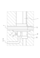
- FIG. 4 is a diagram showing the blocking cap 14 fixed to the structure of the underground structure 3, and is a side view of the blocking cap 14.
- the blocking cap 14 has an insertion portion 147 that is inserted into the metal pipeline 1.
- the outer diameter of the insertion portion 147 is approximately equal to the inner diameter of the metal pipeline 1.
- the blocking cap 14 With the insertion portion 147 inserted into the metal pipeline 1, the blocking cap 14 is fixed to the structure of the underground structure 3 from the inside of the structure (side surface) of the underground structure 3. In this manner, the blocking cap 14 can seal one end 1a and the other end 1b of the metal pipeline 1. Airtightness can be further improved by wrapping security tape 148 or the like around the passage opening 143 and the inner pipe 2 for protection.
- the first member 144 and the second member 145 are connected to form the blocking cap 14, so that the one end 1a and the other end 1b of the metal pipeline 1 can be sealed with the blocking cap 14 while the inner tube 2 is laid inside the metal pipeline 1.
- the blocking cap 14 since an example is used in which the inner pipe 2 is laid inside the metal pipeline 1, the blocking cap 14 has a passage hole 143. However, if the inner pipe 2 is not laid inside the metal pipeline 1, the blocking cap 14 does not need to have a passage hole 143.
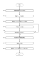
- step S11 remove moisture from inside the metal pipe 1 by spraying an adsorbent inside the metal pipe 1 or by using a suction device.
- a blocking cap 14a is attached to one end 1a of the metal pipeline 1, and a blocking cap 14b is attached to the other end 1b of the metal pipeline 1 (step S12).
- the blocking cap 14 is attached to the metal pipeline 1 when the inner tube 2 has passed through the passage opening 143, and seals one end 1a and the other end 1b of the metal pipeline 1.
- the blocking cap 14 can be attached to the metal pipeline 1 in this state by connecting the first member 144 and the second member 145.
- the inner tube 2 can be placed through the passage opening 143.
- the blocking cap 14 attaching the blocking cap 14 to one end 1a and the other end 1b of the metal pipeline 1, the one end 1a and the other end 1b of the metal pipeline 1 can be sealed with the inner tube 2 passing through the passage opening 143 (first passage opening) of the blocking cap 14a and the passage opening 143 (second passage opening) of the blocking cap 14b.
- the connecting opening 141 of the blocking cap 14 is left open.
- the air supply hose 11a is attached to the connection port 141 of the blocking cap 14a, and the exhaust hose 12a is attached to the connection port 141 of the blocking cap 14b (step S13).
- the supply device 11 supplies the inert gas to the inside of the metal pipeline 1 via the air supply hose 11a (step S14).
- the exhaust device 12 also starts exhausting the gas inside the metal pipeline 1 via the exhaust hose 12a.
- the measuring device 13 measures the oxygen concentration inside the metal pipeline 1 or the oxygen concentration of the gas discharged from the exhaust hose 12a.
- the measuring device 13 determines whether the measured oxygen concentration is below a predetermined value (step S15). By determining whether the oxygen concentration is below a predetermined value, it is possible to determine whether the gas inside the metal pipeline 1 is being replaced from air to inert gas, i.e., whether the filling of the inside of the metal pipeline 1 with inert gas has been completed.
- step S15 No If it is determined that the measured oxygen concentration is not equal to or lower than the predetermined value (step S15: No), the process returns to step S14, and the supply device 11 continues to supply the inert gas.
- step S15 If it is determined that the measured oxygen concentration is equal to or lower than the predetermined value (step S15: Yes), the supply device 11 stops the supply of the inert gas (step S16). In addition, the exhaust device 12 stops exhausting the gas inside the metal pipe 1. In other words, when the filling of the inside of the metal pipe 1 with the inert gas is completed, the supply of the inert gas is stopped.
- connection port 141 (first connection port) of the blocking cap 14a is blocked by the shutoff valve 142 (first shutoff valve), and the connection port 141 (second connection port) of the blocking cap 14b is blocked by the shutoff valve 142 (second shutoff valve) (step S17). In this way, the interior of the metal pipeline 1 can be filled with the inert gas.
- step S18 After the shutoff valve 142 closes the connection port 141, the air supply hose 11a and the exhaust hose 12a are removed (step S18).
- the corrosion prevention method using the corrosion prevention system 10 thus includes the steps of sealing one end 1a of the metal pipeline 1 with a blocking cap 14a and sealing the other end 1b of the metal pipeline 1 with a blocking cap 14b (step S12), connecting the air supply hose 11a to the connection port 141 of the blocking cap 14a, connecting the exhaust hose 12a to the connection port 141 of the blocking cap 14b, and supplying inert gas to the inside of the metal pipeline 1 via the air supply hose 11a (steps S13 and S14), and, after the filling of the inside of the metal pipeline 1 with inert gas is completed, closing the connection port 141 of the blocking cap 14a with the shutoff valve 142 and closing the connection port 141 of the blocking cap 14b with the shutoff valve 142 (step S17).
- the inside of the metal pipeline 1 can be filled with inert gas by sealing one end 1a and the other end 1b of the metal pipeline 1 with a blocking cap 14, supplying inert gas to the inside of the metal pipeline 1 via the air supply hose 11a, and then blocking the connection port 141 of the blocking cap 14.
- the progress of corrosion due to various oxidation reactions caused by contact with the atmosphere, water, or other metals can be suppressed inside the metal pipeline 1.
- the progress of corrosion is suppressed by filling the inside of the metal pipeline 1 with inert gas, so the inner diameter of the metal pipeline 1 is not changed. Therefore, there is no effect on the performance of laying the inner pipe 2 inside the metal pipeline 1.
- a method for preventing corrosion of a metal pipeline buried underground comprising the steps of: one end of the metal conduit is sealed with a first blocking cap having a first connecting port and a first shutoff valve capable of closing the first connecting port, and the other end of the metal conduit is sealed with a second blocking cap having a second connecting port and a second shutoff valve capable of closing the second connecting port; an air supply hose is connected to the first connecting port, an exhaust hose is connected to the second connecting port, and an inert gas is supplied to the inside of the metal pipe via the air supply hose; a first shutoff valve for closing the first connecting port and a second shutoff valve for closing the second connecting port after the inert gas has been filled into the interior of the metal pipeline;
- the corrosion prevention method In the corrosion prevention method according to claim 1, Measure the oxygen concentration inside the metal pipe or the oxygen concentration of the gas discharged from the exhaust hose; The corrosion prevention method further comprises stopping the supply of the inert gas when the measured oxygen concentration becomes equal to or lower than a predetermined value.
- an inner pipe is laid in the metal pipeline, the inner pipe being inserted into one end of the metal pipeline and exposed from the other end of the metal pipeline; the first closure cap has a first passage opening through which the inner tube passes, The second closure cap has a second passage opening through which the inner tube passes.
- a corrosion protection system for an underground buried metal pipeline comprising: a first blocking cap having a first connecting port and a first shutoff valve capable of closing the first connecting port and configured to seal one end of the metal pipe; a second blocking cap having a second connecting port and a second shutoff valve capable of closing the second connecting port and sealing the other end of the metal pipe; a supply device that supplies an inert gas to the inside of the metal pipeline through an air supply hose connected to the first connection port; an exhaust device that exhausts gas from inside the metal pipe through an exhaust hose connected to the second connection port, a corrosion prevention system, wherein after the inert gas has been completely filled into the interior of the metal pipeline, the first connecting port is closed by the first shutoff valve and the second connecting port is closed by the second shutoff valve.
Landscapes
- Engineering & Computer Science (AREA)
- General Engineering & Computer Science (AREA)
- Mechanical Engineering (AREA)
- Pipe Accessories (AREA)
Abstract
Un procédé de prévention de corrosion selon la présente invention comprend : une étape consistant à sceller une extrémité (1a) d'un conduit métallique (1) avec un capuchon de fermeture (14a) et à sceller une autre extrémité (1b) du conduit métallique (1) avec un capuchon de fermeture (14b) ; une étape consistant à relier un tuyau d'alimentation en gaz (11a) à un orifice de raccordement (141) du capuchon de fermeture (14a), à raccorder un tuyau d'évacuation de gaz (12a) à un orifice de raccordement (141) du capuchon de fermeture (14b), et à fournir un gaz inerte à l'intérieur du conduit métallique (1) par l'intermédiaire du tuyau d'alimentation en gaz (11a) ; et une étape consistant à fermer les orifices de raccordement (141) du capuchon de fermeture (14a) et du capuchon de fermeture (14b) avec une soupape d'arrêt (142) une fois que le remplissage du gaz inerte à l'intérieur du conduit métallique (1) est effectué.
Priority Applications (1)
| Application Number | Priority Date | Filing Date | Title |
|---|---|---|---|
| PCT/JP2023/021059 WO2024252532A1 (fr) | 2023-06-06 | 2023-06-06 | Procédé de prévention de la corrosion et système de prévention de la corrosion |
Applications Claiming Priority (1)
| Application Number | Priority Date | Filing Date | Title |
|---|---|---|---|
| PCT/JP2023/021059 WO2024252532A1 (fr) | 2023-06-06 | 2023-06-06 | Procédé de prévention de la corrosion et système de prévention de la corrosion |
Publications (1)
| Publication Number | Publication Date |
|---|---|
| WO2024252532A1 true WO2024252532A1 (fr) | 2024-12-12 |
Family
ID=93795516
Family Applications (1)
| Application Number | Title | Priority Date | Filing Date |
|---|---|---|---|
| PCT/JP2023/021059 Ceased WO2024252532A1 (fr) | 2023-06-06 | 2023-06-06 | Procédé de prévention de la corrosion et système de prévention de la corrosion |
Country Status (1)
| Country | Link |
|---|---|
| WO (1) | WO2024252532A1 (fr) |
Citations (6)
| Publication number | Priority date | Publication date | Assignee | Title |
|---|---|---|---|---|
| JPS499359B1 (fr) * | 1966-08-10 | 1974-03-04 | ||
| JPH09310793A (ja) * | 1996-05-23 | 1997-12-02 | Osaka Gas Co Ltd | 管端用キャップ |
| JP2000310391A (ja) * | 1999-04-28 | 2000-11-07 | Nkk Corp | ベロ−ズ型伸縮継手 |
| JP2004340328A (ja) * | 2003-05-19 | 2004-12-02 | Japan Gas Association | エアパージ装置 |
| JP2009257492A (ja) * | 2008-04-17 | 2009-11-05 | Nippon Steel Corp | ガス配管の補修方法及びその補修構造 |
| US20220112977A1 (en) * | 2020-10-13 | 2022-04-14 | General Air Products, Inc. | Corrosion risk reduction apparatus, corrosion risk reduction detection device and corrosion risk reduction systems and methods |
-
2023
- 2023-06-06 WO PCT/JP2023/021059 patent/WO2024252532A1/fr not_active Ceased
Patent Citations (6)
| Publication number | Priority date | Publication date | Assignee | Title |
|---|---|---|---|---|
| JPS499359B1 (fr) * | 1966-08-10 | 1974-03-04 | ||
| JPH09310793A (ja) * | 1996-05-23 | 1997-12-02 | Osaka Gas Co Ltd | 管端用キャップ |
| JP2000310391A (ja) * | 1999-04-28 | 2000-11-07 | Nkk Corp | ベロ−ズ型伸縮継手 |
| JP2004340328A (ja) * | 2003-05-19 | 2004-12-02 | Japan Gas Association | エアパージ装置 |
| JP2009257492A (ja) * | 2008-04-17 | 2009-11-05 | Nippon Steel Corp | ガス配管の補修方法及びその補修構造 |
| US20220112977A1 (en) * | 2020-10-13 | 2022-04-14 | General Air Products, Inc. | Corrosion risk reduction apparatus, corrosion risk reduction detection device and corrosion risk reduction systems and methods |
Similar Documents
| Publication | Publication Date | Title |
|---|---|---|
| US10718463B2 (en) | System and method for protecting one or more pipes against corrosion and corrosion-protected pipe | |
| CN107339524A (zh) | 一种新型的管件及其管道系统 | |
| CA2354226A1 (fr) | Appareil robotique et methode d'entretien non destructif de canalisations croisees | |
| BR9909078A (pt) | Sistema e aparelho para revestir internamenteuma junta ou outra descontinuidade em umatubulação de gás vivo | |
| Krasovskaya et al. | Designing trenchless technologies in oil and gas engineering | |
| WO2024252532A1 (fr) | Procédé de prévention de la corrosion et système de prévention de la corrosion | |
| KR100696318B1 (ko) | 관로구용 연결관 결속장치 | |
| US12510203B2 (en) | Methods and systems for sealing a service pipe | |
| US20210285590A1 (en) | Methods, systems, and apparatus for providing access for telecommunication cables in utility piping | |
| CN110486532B (zh) | 一种非开挖管道修复施工工艺 | |
| JP7171036B2 (ja) | パイプシステムの漏れ又は漏れのリスクを減少させる方法 | |
| US6505783B1 (en) | Method for rehabilitating low pressure service mains connections | |
| CN205578947U (zh) | 管道对接焊口的补口防腐装置 | |
| CN206875017U (zh) | 一种石油管道应急封堵分流设备 | |
| JPH03249493A (ja) | 地中埋設配管の防食構築物およびその施工方法 | |
| JP6802563B2 (ja) | 更生管の固定具及び更生管の固定具敷設方法 | |
| WO2024252533A1 (fr) | Procédé de pose et système de pose | |
| CN120819709A (zh) | 一种油田内穿插管钢包裹接头的施工方法 | |
| US20230021427A1 (en) | Casing system and method for pipeline reinforcement and repair | |
| Bylin et al. | New measurement data has implications for quantifying natural gas losses from cast iron distribution mains | |
| JP4786227B2 (ja) | 既設管路のライニング工法 | |
| JPH0413485B2 (fr) | ||
| WO2025099915A1 (fr) | Pipeline et procédé d'inspection de pipeline | |
| Konno | Development of the “Gray-Buster-Advance Lining” method for renovation of gray cast-iron pipes | |
| Thomas | 2-Layer Polyethylene Plant Applied Mainline Coating for Use in Water and Wastewater Pipeline Applications |
Legal Events
| Date | Code | Title | Description |
|---|---|---|---|
| 121 | Ep: the epo has been informed by wipo that ep was designated in this application |
Ref document number: 23940637 Country of ref document: EP Kind code of ref document: A1 |
|
| NENP | Non-entry into the national phase |
Ref country code: DE |