WO2024252533A1 - Procédé de pose et système de pose - Google Patents
Procédé de pose et système de pose Download PDFInfo
- Publication number
- WO2024252533A1 WO2024252533A1 PCT/JP2023/021060 JP2023021060W WO2024252533A1 WO 2024252533 A1 WO2024252533 A1 WO 2024252533A1 JP 2023021060 W JP2023021060 W JP 2023021060W WO 2024252533 A1 WO2024252533 A1 WO 2024252533A1
- Authority
- WO
- WIPO (PCT)
- Prior art keywords
- pipeline
- fixing jig
- injection
- pipe
- injection port
- Prior art date
- Legal status (The legal status is an assumption and is not a legal conclusion. Google has not performed a legal analysis and makes no representation as to the accuracy of the status listed.)
- Ceased
Links
Images


Classifications
-
- E—FIXED CONSTRUCTIONS
- E03—WATER SUPPLY; SEWERAGE
- E03F—SEWERS; CESSPOOLS
- E03F3/00—Sewer pipe-line systems
- E03F3/04—Pipes or fittings specially adapted to sewers
Definitions
- This disclosure relates to an installation method and system.
- Non-Patent Document 1 In order to utilize hydrogen energy to achieve carbon neutrality, hydrogen pipelines for transporting hydrogen are being installed (see Non-Patent Document 1). Conventionally, when hydrogen pipelines are installed underground, the pipelines are buried directly in the ground. By burying the pipelines directly in the ground, the load in the soil acts as a restraining force, suppressing deformation due to elongation of the buried pipelines.
- inner pipes for hydrogen pipelines and the like may also be laid inside existing pipelines that are already buried underground, such as communication pipelines.
- flexible pipes are used as the inner pipes to accommodate the unevenness and curves of the existing pipeline.
- the flexible pipe is fixed in place with metal fittings or the like to restrict its extension.
- the purpose of this disclosure is to provide an installation method and installation system that can suppress deformation of the second pipeline installed inside the first pipeline.
- the laying method is a laying method for laying a second pipeline inside a first pipeline buried underground, and includes the steps of: fixing the second pipeline and sealing one end of the first pipeline with a first fixing jig having an injection port and a shutoff valve capable of closing the injection port, while the second pipeline is inserted into one end of the first pipeline and exposed from the other end of the first pipeline, and fixing the second pipeline and sealing the other end of the first pipeline with a second fixing jig; injecting a filler that is inactive with respect to the first pipeline and the second pipeline from a third pipeline inserted into the injection port between the first pipeline and the second pipeline; and, after the filling of the filler between the first pipeline and the second pipeline is completed, pulling out the third pipeline from the first pipeline and closing the injection port with the shutoff valve.
- the installation system is an installation system for laying a second pipeline inside a first pipeline buried underground, and includes a traction device that traction-exposes the second pipeline inserted from one end of the first pipeline from the other end of the first pipeline, an injection port, and a shutoff valve that can shut off and open the injection port, and fixes the second pipeline and seals one end of the first pipeline when the second pipeline is inserted from one end of the first pipeline.
- a first fixing jig for fixing the second pipeline in a state in which the second pipeline is exposed from the other end of the first pipeline and sealing the other end of the first pipeline; an injection device for injecting a filler that is inactive with respect to the first pipeline and the second pipeline from a third pipeline inserted into the injection port between the first pipeline and the second pipeline; and a winding device for pulling out the third pipeline from the first pipeline after the filling of the filler between the first pipeline and the second pipeline is completed.
- the installation method and system disclosed herein can suppress deformation of the second pipeline installed inside the first pipeline.
- FIG. 1 is a diagram illustrating a configuration example of an installation system according to an embodiment of the present disclosure.
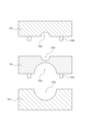
- FIG. 2 is a front view of the fixing jig 15 shown in FIG. 2 is a diagram showing members constituting the fixing jig 15 shown in FIG. 1 before being connected together.
- FIG. 2 is a diagram showing a state in which the fixing jig 15 shown in FIG. 1 is fixed to one end of an existing pipeline.
- FIG. 2 is a front view of the fixing jig 16 shown in FIG. 2 is a diagram showing members constituting the fixing jig 16 shown in FIG. 1 before being connected together.
- 2 is a flowchart for explaining a laying method using the laying system shown in FIG. 1 .
- FIG. 1 is a diagram showing an example of the configuration of an installation system 10 according to an embodiment of the present disclosure.
- the installation system 10 according to this embodiment is for installing an inner pipeline as a second pipeline inside an existing pipeline 1 as a first pipeline, such as a communication pipeline, buried underground.
- the inner pipeline is assumed to be a flexible pipe 2 having flexibility.
- the existing pipeline 1 is provided so as to connect underground structures 4 installed underground, such as manholes, handholes, or tunnels, for example, as shown in FIG. 1.
- the installation system 10 includes a sending device 11, a towing device 12, a winding device 13, an injection device 14, and fixing devices 15 and 16.
- the sending device 11, the towing device 12, the winding device 13, and the injection device 14 are installed, for example, on the ground.
- the delivery device 11 has the function of storing the flexible tube 2.
- the delivery device 11 can deliver the stored flexible tube 2 in accordance with the towing of the flexible tube 2 by the towing device 12 described below.
- the towing device 12 is equipped with a towing jig 12a to which the flexible pipe 2 can be fixed, and can tow the flexible pipe 2 fixed to the towing jig 12a at a speed specified by an operator or the like.
- the towing device 12 tows the flexible pipe 2 inserted from one end 1a of the existing pipeline 1 from the other end 1b of the existing pipeline 1, and exposes it from the other end 1b of the existing pipeline 1.
- the towing device 12 can tow the injection pipe 3 together with the flexible pipe 2.
- the winding device 13 has the function of storing the injection tube 3 as the third pipeline.
- the winding device 13 can feed out the stored injection tube 3 in accordance with the towing device 12 pulling the flexible pipe 2 to which the injection tube 3 is fixed.
- the winding device 13 can also wind up the injection tube 3 pulled out by the towing device 12 at a speed specified by an operator or the like.
- the winding device 13 can pull out the injection tube 3 from the existing pipeline 1 after the injection device 14, described below, has completed filling the space between the existing pipeline 1 and the flexible pipe 2 with the filling material.
- the injection device 14 has a function of containing a filler that is inactive to the existing pipeline 1 and the flexible pipe 2.
- the filler is not particularly limited as long as it is inactive to the existing pipeline 1 and the flexible pipe 2 (i.e., it does not cause corrosion of the existing pipeline 1 and the flexible pipe 2) and can fill the gap between the existing pipeline 1 and the flexible pipe 2.
- the filler is, for example, dry sand. In the following description, the filler is dry sand.
- the injection device 14 injects the dry sand, which is the filler to be contained, from the injection pipe 3 between the existing pipeline 1 and the flexible pipe 2.
- the injection device 14 can discharge the contained dry sand at a speed specified by an operator or the like.
- the injection device 14 may inject at least one of an oxygen scavenger and a desiccant together with the dry sand.
- an oxygen scavenger and a desiccant together with the dry sand.
- Figure 2 is a front view of the fixing jig 15.
- the fixture 15 has a passage port 151, an injection port 152, and a shutoff valve 153.
- the passage port 151 which serves as the first passage port, allows the flexible pipe 2 to pass through and can fix the flexible pipe 2 that has passed through the passage port 151.
- a half fixing plate 151a is provided on the inner periphery of the passage port 151.
- the position of the fixing plate 151a can be adjusted in the radial direction of the passage port 151 by the adjustment screw 151b.
- the flexible pipe 2 that has passed through the passage port 151 can be fixed by adjusting the position of the fixing plate 151a by the adjustment screw 151b to match the thickness of the flexible pipe 2.
- the injection port 152 allows the injection tube 3 to pass through.
- the shutoff valve 153 can close and open the injection port 152.
- the fixing jig 15 includes a first member 154, a second member 155 connectable to the first member 154, and a third member 156 connectable to the second member 155. As shown in FIG. 3, the first member 154, the second member 155, and the third member 156 are provided separately, and the fixing jig 15 is formed by connecting these members. Note that the fixing plate 151a, the adjustment screw 151b, and the shutoff valve 153 are omitted from FIG. 3.
- the first member 154 is a rectangular member in a plan view, and has a semicircular recess 154a on one side.
- the second member 155 is a rectangular member in a plan view, with a semicircular recess 155a on one side and a semicircular recess 155b on the other side opposite the first side.
- the first member 154 and the second member 155 are connected, for example, by a screw 155c, so that the side on which the recess 154a is provided is in contact with the side on which the recess 155a is provided.
- the passage opening 151 is formed by connecting the first member 154 and the second member 155.
- the third member 156 is a rectangular member in a plan view, and has a semicircular recess 156a on one side.
- the second member 155 and the third member 156 are connected, for example, by a screw 156b, so that the side on which the recess 155b is provided is in contact with the side on which the recess 156a is provided.
- the injection port 152 is formed by connecting the second member 155 and the third member 156.
- the fixing jig 15 has a fixing portion 157 for fixing to the frame of the underground structure 4 with an anchor or a screw.
- FIG. 4 shows the state in which the fixing jig 15 is fixed to the frame of the underground structure 4.
- the fixing jig 15 has an insertion portion 158 that is inserted into the existing pipeline 1 from one end 1a of the existing pipeline 1.
- the outer diameter of the insertion portion 158 is approximately equal to the inner diameter of the existing pipeline 1.
- the fixing jig 15 With the insertion portion 158 inserted into the existing pipeline 1, the fixing jig 15 is fixed to the structure of the underground structure 4 from the inside of the structure (side surface) of the underground structure 4. In this way, the fixing jig 15 can seal one end 1a of the existing pipeline 1. Airtightness can be further improved by wrapping security tape 159 or the like around the passage opening 151 and the flexible pipe 2 for protection.
- the fixing jig 15 is formed by connecting the first member 154, the second member 155, and the third member 156, so that after the flexible pipe 2 and the injection pipe 3 are inserted into the existing pipeline 1, the fixing jig 15 can seal one end 1a of the existing pipeline 1 with the flexible pipe 2 passing through the passage port 151 and the injection pipe 3 passing through the injection port 152.
- the fixing jig 16 as the second fixing jig can fix the flexible pipe 2 in a state where the flexible pipe 2 is exposed from the other end 1b of the existing pipeline 1. As shown in FIG. 1, the fixing jig 16 is fixed to the body of the underground structure 4 at the other end 1b of the existing pipeline 1, and seals the other end 1b of the existing pipeline 1.
- Figure 5 is a front view of the fixing jig 16.
- the fixing jig 16 has a passage opening 161.
- the passage opening 161 allows the flexible pipe 2 to pass through and can also fix the flexible pipe 2 that has passed through the passage opening 161.
- a half fixing plate 161a is provided on the inner periphery of the passage opening 161.
- the position of the fixing plate 161a can be adjusted in the radial direction of the passage opening 161 by the adjustment screw 161b.
- the flexible pipe 2 that has passed through the passage opening 161 can be fixed by adjusting the position of the fixing plate 161a by the adjustment screw 161b to match the thickness of the flexible pipe 2.
- the fixing jig 16 includes a fourth member 164 and a fifth member 165 that can be connected to the fourth member 164. As shown in FIG. 6, the fourth member 164 and the fifth member 165 are provided separately, and are connected to form the fixing jig 16.
- the fourth member 164 is a rectangular member in a plan view, and has a semicircular recess 164a on one side.
- the fifth member 165 is a rectangular member in a plan view, and has a semicircular recess 165a on one side.
- the fourth member 164 and the fifth member 165 are connected, for example, by a screw 165c, so that the side on which the recess 164a is provided and the side on which the recess 165a is provided are in contact with each other.
- the passage opening 161 is formed by connecting the fourth member 164 and the fifth member 165.
- the fixing jig 16 has a fixing portion 167 for fixing to the frame of the underground structure 4 with an anchor or a screw.
- the method of fixing to the underground structure 4 is the same as for the fixing jig 15, so a description thereof will be omitted.
- a towing jig 12a is attached to the tip of a flexible pipe 2 inserted from one end 1a of the existing pipeline 1.
- An injection pipe 3 is tied to the flexible pipe 2 near its tip. With the injection pipe 3 tied to the flexible pipe 2, the flexible pipe 2 is towed by the towing device 12, causing the flexible pipe 2 to be sent out from the sending device 11 and the injection pipe 3 to be sent out from the winding device 13, and the flexible pipe 2 and the injection pipe 3 to be pulled into the existing pipeline 1.
- the towing by the towing device 12 is stopped.
- the binding between the flexible pipe 2 and the injection pipe 3 is released.
- the winding device 13 winds up the injection pipe 3 so that the tip of the injection pipe 3 is located inside the existing pipeline 1.
- the flexible pipe 2 is exposed from the other end 1b of the existing pipeline 1, and the injection pipe 3 can be laid in a state where it is placed in the existing pipeline 1. It is preferable that the injection pipe 3 is positioned so that the tip of the injection pipe 3 is located near the other end 1b of the existing pipeline 1.
- fixing jigs 15, 16 are attached to the existing pipeline 1 (step S12). Specifically, the fixing jig 15 fixes the flexible pipe 2 and seals one end 1a of the existing pipeline 1. The fixing jig 16 fixes the flexible pipe 2 and seals the other end 1b of the existing pipeline 1.
- the fixing jig 15 is attached to the existing pipeline 1 with the flexible pipe 2 passing through the passage port 151 and the injection pipe 3 passing through the injection port 152, and seals one end 1a of the existing pipeline 1.
- the fixing jig 15 can be attached to the existing pipeline 1 in this state by sequentially connecting the first member 154, the second member 155, and the third member 156.
- the flexible tube 2 can be placed in a state of passing through the passage port 151.
- the second member 155 and the third member 156 with the injection tube 3 placed in the recess 155b of the second member 155 and the recess 156a of the third member 156, the injection tube 3 can be placed in a state of passing through the injection port 152.
- the fixing jig 15 to one end 1a of the existing pipeline 1 and adjusting the position of the fixing plate 151a with the adjustment screw 151b, the one end 1a of the existing pipeline 1 can be sealed with the flexible pipe 2 fixed by the fixing jig 15.
- the fixing jig 16 is attached to the existing pipeline 1 with the flexible pipe 2 passing through the passage opening 161, and seals the other end 1b of the existing pipeline 1.
- the fixing jig 16 can be attached to the existing pipeline 1 in this state by connecting the fourth member 164 and the fifth member 165.
- the flexible tube 2 can be placed in a state of passing through the passage opening 161.
- the injection device 14 starts injecting dry sand from the injection pipe 3 inserted into the injection port 152 into the space between the existing pipeline 1 and the flexible pipe 2 (step S13).
- the winding device 13 starts winding the injection pipe 3 at a constant speed (step S14).
- the dry sand is injected sequentially toward one end 1a of the existing pipeline 1.
- the speed at which the injection pipe 3 is wound is set so that the space between the existing pipeline 1 and the flexible pipe 2 (between the inner diameter of the existing pipeline 1 and the outer diameter of the flexible pipe 2) is sufficiently filled with dry sand (at least to the extent that the flexible pipe 2 is buried in dry sand).
- the injection device 14 stops injecting the dry sand (step S15).
- step S16 After the injection of the dry sand is stopped, the injection port 152 is closed by the shutoff valve 153 of the fixing jig 15 (step S16). This seals the existing pipeline 1 with the dry sand filled between the existing pipeline 1 and the flexible pipe 2.
- the laying method using the laying system 10 thus includes the steps of: fixing the flexible pipe 2 with the fixing jig 15 and sealing one end 1a of the existing pipeline 1 while the flexible pipe 2 is inserted into one end 1a and exposed from the other end 1b of the existing pipeline 1; fixing the flexible pipe 2 with the fixing jig 15 and sealing the other end 1b of the existing pipeline with the fixing jig 16 (steps S11 and S12); injecting a filler (e.g., dry sand) that is inactive to the existing pipeline 1 and the flexible pipe 2 between the existing pipeline 1 and the flexible pipe 2 from the injection pipe 3 inserted into the injection port 152 (steps S13 and S14); and, after the filling of the filler between the existing pipeline and the flexible pipe 2 is completed, pulling out the injection pipe 3 from the existing pipeline 1 and closing the injection port 152 with the shutoff valve 153 (steps S15 and S16).
- a filler e.g., dry sand
- the second pipeline By filling the gap between the first pipeline (existing pipeline 1) and the second pipeline (flexible pipe 2), the second pipeline is restrained by the reaction force of the filled pipeline, and deformation such as extension and bending of the second pipeline inside the first pipeline can be suppressed. Therefore, deformation of the second pipeline laid inside the first pipeline can be suppressed.
- the existing pipeline 1 already buried underground is used to lay the second pipeline, which reduces the scope of construction such as cutting, making it possible to lay an economical hydrogen pipeline.
- the filler is filled between the first pipeline and the second pipeline, even if gas (e.g., hydrogen) leaks from the second pipeline, the space in which the leaked gas stagnates between the first pipeline and the second pipeline is reduced, so that the stagnation of the leaked gas can be suppressed.
- gas e.g., hydrogen
- a method for laying a second pipeline inside a first pipeline buried underground comprising the steps of: a first fixing jig having an injection port and a shutoff valve capable of closing the injection port, the second pipe is fixed and the first pipe is sealed at one end thereof, and a second fixing jig is used to fix the second pipe and seal the other end thereof, with the second pipe being inserted into the first pipe and exposed from the other end thereof; injecting a filler that is inactive with respect to the first pipeline and the second pipeline from a third pipeline inserted into the injection port between the first pipeline and the second pipeline; the third pipeline is pulled out from the first pipeline, and the injection port is closed by the shutoff valve after the filling of the filler between the first pipeline and the second pipeline is completed.
- the installation method further comprises injecting at least one of an oxygen scavenger and a desiccant between the first pipeline and the second pipeline.
- the first fixing jig has a first member, a second member connectable to the first member, and a third member connectable to the second member, the first member and the second member being connected to each other to form a first passage port through which the first pipeline passes, and the second member and the third member being connected to each other to form the injection port
- the second fixing jig has a fourth member and a fifth member connectable to the fourth member, and a second passage port through which the first pipeline passes is formed by connecting the fourth member and the fifth member; inserting the second pipeline and the third pipeline from one end of the first pipeline, exposing the second pipeline from the other end of the first pipeline, and arranging the third pipeline inside the first pipeline; connecting the first member and the second member with the second pipeline passing through the first passage port, connecting the second member and the third member with the third pipeline passing through the injection port, and connecting the fourth member and the fifth member with the second pipeline passing through the second passage port.
- a system for laying a second pipeline inside a first pipeline buried underground comprising: a pulling device that pulls the second pipeline inserted from one end of the first pipeline from the other end side of the first pipeline to expose the second pipeline from the other end of the first pipeline; a first fixing jig having an injection port and a shutoff valve capable of shutting off and opening the injection port, the first fixing jig fixing the second pipe and sealing the one end of the first pipe in a state in which the second pipe is inserted into the one end of the first pipe; a second fixing jig that fixes the second pipeline and seals the other end of the first pipeline in a state in which the second pipeline is exposed from the other end of the first pipeline; an injection device that injects a filler that is inactive with respect to the first pipeline and the second pipeline from a third pipeline inserted into the injection port between the first pipeline and the second pipeline; and a winding device that pulls out the third pipeline from the first pipeline after the filling of the filler between the first
Landscapes
- Health & Medical Sciences (AREA)
- Life Sciences & Earth Sciences (AREA)
- Engineering & Computer Science (AREA)
- Hydrology & Water Resources (AREA)
- Public Health (AREA)
- Water Supply & Treatment (AREA)
- Underground Structures, Protecting, Testing And Restoring Foundations (AREA)
Abstract
La présente invention concerne un procédé de pose, qui comprend : une étape dans laquelle, dans un état dans lequel une deuxième canalisation est insérée à partir d'une première extrémité d'une première canalisation et est exposée à partir de l'autre extrémité de la première canalisation, un gabarit de fixation (15) est utilisé pour fixer la deuxième canalisation et sceller la première extrémité de la première canalisation et un gabarit de fixation (16) est utilisé pour fixer la deuxième canalisation et sceller l'autre extrémité de la première canalisation ; une étape dans laquelle une charge qui est inerte par rapport à la première canalisation et la deuxième canalisation est injectée dans l'espace entre la première canalisation et la deuxième canalisation à partir d'une troisième canalisation insérée dans un orifice d'injection (152) ; et une étape dans laquelle, après achèvement du garnissage de la charge dans l'espace entre la première canalisation et la deuxième canalisation, la troisième canalisation est retirée de la première canalisation et l'orifice d'injection (152) est fermé au moyen d'une valve d'arrêt (153).
Priority Applications (1)
| Application Number | Priority Date | Filing Date | Title |
|---|---|---|---|
| PCT/JP2023/021060 WO2024252533A1 (fr) | 2023-06-06 | 2023-06-06 | Procédé de pose et système de pose |
Applications Claiming Priority (1)
| Application Number | Priority Date | Filing Date | Title |
|---|---|---|---|
| PCT/JP2023/021060 WO2024252533A1 (fr) | 2023-06-06 | 2023-06-06 | Procédé de pose et système de pose |
Publications (1)
| Publication Number | Publication Date |
|---|---|
| WO2024252533A1 true WO2024252533A1 (fr) | 2024-12-12 |
Family
ID=93795486
Family Applications (1)
| Application Number | Title | Priority Date | Filing Date |
|---|---|---|---|
| PCT/JP2023/021060 Ceased WO2024252533A1 (fr) | 2023-06-06 | 2023-06-06 | Procédé de pose et système de pose |
Country Status (1)
| Country | Link |
|---|---|
| WO (1) | WO2024252533A1 (fr) |
Citations (8)
| Publication number | Priority date | Publication date | Assignee | Title |
|---|---|---|---|---|
| JPS52144823A (en) * | 1976-05-28 | 1977-12-02 | Asahi Giken Kk | Piping method for hydrocarbonic fluid |
| JPS56102929U (fr) * | 1980-01-09 | 1981-08-12 | ||
| JP2001193841A (ja) * | 1999-11-19 | 2001-07-17 | Hilti Ag | 密封装置 |
| JP2001211539A (ja) * | 2000-01-27 | 2001-08-03 | Furukawa Electric Co Ltd:The | 配線管路 |
| JP2002051443A (ja) * | 2000-08-01 | 2002-02-15 | Sumitomo Electric Ind Ltd | 管路内布設ケ−ブル線路及び同ケ−ブル線路の形成方法 |
| JP2006138351A (ja) * | 2004-11-10 | 2006-06-01 | Sekisui Chem Co Ltd | 2重配管システム |
| JP2010101104A (ja) * | 2008-10-24 | 2010-05-06 | Mirai Ind Co Ltd | 管引出口形成具 |
| CN109654303A (zh) * | 2018-12-13 | 2019-04-19 | 中冶天工集团有限公司 | 一种用于综合管廊穿线管的螺栓充气式密封装置及其安装方法 |
-
2023
- 2023-06-06 WO PCT/JP2023/021060 patent/WO2024252533A1/fr not_active Ceased
Patent Citations (8)
| Publication number | Priority date | Publication date | Assignee | Title |
|---|---|---|---|---|
| JPS52144823A (en) * | 1976-05-28 | 1977-12-02 | Asahi Giken Kk | Piping method for hydrocarbonic fluid |
| JPS56102929U (fr) * | 1980-01-09 | 1981-08-12 | ||
| JP2001193841A (ja) * | 1999-11-19 | 2001-07-17 | Hilti Ag | 密封装置 |
| JP2001211539A (ja) * | 2000-01-27 | 2001-08-03 | Furukawa Electric Co Ltd:The | 配線管路 |
| JP2002051443A (ja) * | 2000-08-01 | 2002-02-15 | Sumitomo Electric Ind Ltd | 管路内布設ケ−ブル線路及び同ケ−ブル線路の形成方法 |
| JP2006138351A (ja) * | 2004-11-10 | 2006-06-01 | Sekisui Chem Co Ltd | 2重配管システム |
| JP2010101104A (ja) * | 2008-10-24 | 2010-05-06 | Mirai Ind Co Ltd | 管引出口形成具 |
| CN109654303A (zh) * | 2018-12-13 | 2019-04-19 | 中冶天工集团有限公司 | 一种用于综合管廊穿线管的螺栓充气式密封装置及其安装方法 |
Similar Documents
| Publication | Publication Date | Title |
|---|---|---|
| US8668406B2 (en) | Subsea cable installation | |
| US4979296A (en) | Method for fabricating helical flowline bundles | |
| KR20020056897A (ko) | 지중관로 내에 통신 케이블의 부설 방법과 부설 구조 및부설에 사용되는 부재 | |
| US20240336027A1 (en) | Methods for intelligent composite renewal system for standalone, storage, and renewed pipelines, including for reduced carbon emission and for conversion of in place pipelines for conveyance of hydrogen and other clean fuels | |
| BR112016022137B1 (pt) | desenvolvimento e amarração direta de tubulações submarinas | |
| US20220003336A1 (en) | Method for installing a gas transportation arrangement | |
| WO2024252533A1 (fr) | Procédé de pose et système de pose | |
| JP4490326B2 (ja) | 地中埋設ケーブル等に対する地盤変動時の保護方法及びその保護装置 | |
| US20030103811A1 (en) | Control cable | |
| US20210285590A1 (en) | Methods, systems, and apparatus for providing access for telecommunication cables in utility piping | |
| JP4890312B2 (ja) | 管路橋更生方法 | |
| CN113373922B (zh) | 一种地热能源桩施工设备及其施工方法 | |
| JP6726813B1 (ja) | 既設配管の更新方法 | |
| CN210119617U (zh) | 一种便于光缆敷设更换的管中管结构 | |
| JP7825305B1 (ja) | 配線固定機能付き保護管およびその形成方法 | |
| JP4417891B2 (ja) | 光ファイバーケーブルの敷設方法 | |
| JP4786227B2 (ja) | 既設管路のライニング工法 | |
| WO2024252532A1 (fr) | Procédé de prévention de la corrosion et système de prévention de la corrosion | |
| JP3980258B2 (ja) | 光ファイバーケーブルの敷設方法 | |
| CN217882774U (zh) | 光纤复合架空地线引下光缆防冰冻结构 | |
| JP2007024283A (ja) | ガス漏洩修理方法及びその漏洩修理装置 | |
| KR100904707B1 (ko) | 지중배전선 인입형 절연관 | |
| JPH11198231A (ja) | 光ファイバー敷設対応更生工法、および同更生工事資材 | |
| JP5047913B2 (ja) | ケーブル防護材装着方法及びケーブル防護材装着冶具 | |
| Gillette et al. | Pipe-type cable installation techniques |
Legal Events
| Date | Code | Title | Description |
|---|---|---|---|
| 121 | Ep: the epo has been informed by wipo that ep was designated in this application |
Ref document number: 23940638 Country of ref document: EP Kind code of ref document: A1 |
|
| NENP | Non-entry into the national phase |
Ref country code: DE |