WO2024252534A1 - Modulateur optique - Google Patents
Modulateur optique Download PDFInfo
- Publication number
- WO2024252534A1 WO2024252534A1 PCT/JP2023/021061 JP2023021061W WO2024252534A1 WO 2024252534 A1 WO2024252534 A1 WO 2024252534A1 JP 2023021061 W JP2023021061 W JP 2023021061W WO 2024252534 A1 WO2024252534 A1 WO 2024252534A1
- Authority
- WO
- WIPO (PCT)
- Prior art keywords
- optical waveguide
- type optical
- rib
- type
- width
- Prior art date
- Legal status (The legal status is an assumption and is not a legal conclusion. Google has not performed a legal analysis and makes no representation as to the accuracy of the status listed.)
- Ceased
Links
Images


Classifications
-
- G—PHYSICS
- G02—OPTICS
- G02B—OPTICAL ELEMENTS, SYSTEMS OR APPARATUS
- G02B6/00—Light guides; Structural details of arrangements comprising light guides and other optical elements, e.g. couplings
- G02B6/10—Light guides; Structural details of arrangements comprising light guides and other optical elements, e.g. couplings of the optical waveguide type
- G02B6/12—Light guides; Structural details of arrangements comprising light guides and other optical elements, e.g. couplings of the optical waveguide type of the integrated circuit kind
- G02B6/122—Basic optical elements, e.g. light-guiding paths
- G02B6/125—Bends, branchings or intersections
-
- G—PHYSICS
- G02—OPTICS
- G02F—OPTICAL DEVICES OR ARRANGEMENTS FOR THE CONTROL OF LIGHT BY MODIFICATION OF THE OPTICAL PROPERTIES OF THE MEDIA OF THE ELEMENTS INVOLVED THEREIN; NON-LINEAR OPTICS; FREQUENCY-CHANGING OF LIGHT; OPTICAL LOGIC ELEMENTS; OPTICAL ANALOGUE/DIGITAL CONVERTERS
- G02F1/00—Devices or arrangements for the control of the intensity, colour, phase, polarisation or direction of light arriving from an independent light source, e.g. switching, gating or modulating; Non-linear optics
- G02F1/01—Devices or arrangements for the control of the intensity, colour, phase, polarisation or direction of light arriving from an independent light source, e.g. switching, gating or modulating; Non-linear optics for the control of the intensity, phase, polarisation or colour
Definitions
- This disclosure relates to an optical modulator, and more specifically to an optical modulator using a rib-type optical waveguide.
- multilevel optical modulators using digital coherent technology are playing a major role in realizing high-capacity transceivers that exceed 100 Gbps.
- a multilevel optical modulator splits the input light into two arm optical waveguides, modulates the light propagating through the arm optical waveguides, aligns the phase, and then combines and outputs the resulting interference.
- the multilevel optical modulator has multiple parallel-stage built-in optical modulators (hereafter referred to as MZ modulators: MZMs) capable of zero-chirp drive. This configuration allows independent signals to be added to the amplitude and phase of the light.
- Typical polarization multiplexing IQ optical modulators which are currently being used in communication networks, have a so-called nested structure, in which each arm of a parent MZM is composed of a child MZM.
- Two child MZMs are provided in parallel corresponding to each of the X and Y polarization channels, forming an MZM (Quad-parallel MZM) with a total of four child MZMs.
- the two arms of each child MZM are provided with traveling wave type electrodes to which an RF modulated electrical signal is input to perform a modulation operation on the optical signal propagating in the optical waveguide.
- one of the two such paired child MZMs corresponds to the I channel and the other to the Q channel.
- Such a polarization multiplexed IQ optical modulator applies phase modulation to two optical signals propagating within the optical waveguide of the child MZM by inputting an RF modulated electrical signal to one end of a modulation electrode provided along the arm optical waveguide of the child MZM, thereby generating an electro-optic effect (see, for example, Patent Document 1).
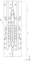
- FIG. 1 shows an example of a high-speed phase modulator using a Mach-Zehnder interferometer, which corresponds to the child MZM that is the basic unit in a polarization multiplexing IQ optical modulator.
- a Mach-Zehnder interferometer which corresponds to the child MZM that is the basic unit in a polarization multiplexing IQ optical modulator.
- the high-mesa type optical waveguides 113a and 113b are connected to rib type optical waveguides 114a and 114b, respectively.
- the rib type optical waveguides 114a and 114b are connected to high-mesa type optical waveguides 115a and 115b, respectively.
- the two rib type optical waveguides 114a and 114b are separated by a separation groove 118.
- the high mesa optical waveguides 115a and 115b are connected to a 2x1 multiplexer 116 having a high mesa optical waveguide structure.
- the 2x1 multiplexer 116 is connected to one high mesa optical waveguide 117.
- the high mesa type optical waveguides 113a, 113b, the rib type optical waveguides 114a, 114b, and the high mesa type optical waveguides 115a, 115b form an arm optical waveguide that connects the 1x2 demultiplexer 112 and the 2x1 multiplexer 116.
- two high-frequency lines 120a, 120b extending in the light propagation direction (x direction) are formed along the arm optical waveguide. The ends of the high-frequency lines 120a, 120b are connected to termination resistors 150a, 150b.
- a plurality of slot electrodes 121a, 121b are formed discretely above the rib type optical waveguides 114a, 114b, respectively, and function as an optical modulator that adds a signal to light by the electro-optic effect.
- the multiple slot electrodes 121a, 121b are connected to the two high-frequency lines 120a, 120b by multiple connection electrodes 122a, 122b, respectively.
- the high mesa optical waveguides 115a, 115b are respectively loaded with thin-film heaters 130a, 130b on the upper side, and function as thermo-optical phase shifters.
- the thin-film heaters 130a, 130b are respectively connected to the two pads 131a, 131b by wiring 132a, 132b.
- the high-speed phase modulator 100 can be divided into a high-mesa optical waveguide region A including a high-mesa optical waveguide 111, a 1 ⁇ 2 splitter 112, and high-mesa optical waveguides 113a and 113b, a high-speed modulation region and rib-type optical waveguide region B including rib-type optical waveguides 114a and 114b, and a high-mesa optical waveguide region C including high-mesa optical waveguides 151 and 115b, a 2 ⁇ 1 multiplexer 116, and a high-mesa optical waveguide 117.
- each optical waveguide has a tapered shape to suppress optical connection loss.
- FIG. 2 shows a cross section taken along line II-II in Figure 1.
- the high mesa optical waveguides 113a and 113b will be described with reference to Figure 2.
- the high mesa optical waveguides 113a and 113b have a structure in which an n-type InP lower cladding layer 202, a p-type InP layer 203, an i-type MQW (Multi Quantum Well) core layer 204, and a high resistance (or non-doped) InP upper cladding layer 205 are stacked on a semi-insulating InP substrate 201.
- the high resistance InP upper cladding layer 205 is formed by etching the n-type InP upper cladding layer and replacing it by regrowth.
- the width W113 of the high-resistance InP upper cladding layer 205 and the i-type MQW core layer 204 in the lateral direction (y direction) perpendicular to the light propagation direction is uniform and is several ⁇ m wide (for example, 2 ⁇ m wide).
- the lateral direction (y direction) of the high mesa optical waveguides 113a and 113b is covered with an organic film (BCB: benzocyclobutene) 206, and the large refractive index difference between the i-type MQW core layer 204 and the organic film 206 realizes lateral light confinement.
- BCB benzocyclobutene
- Figure 3 shows a cross section taken along line III-III in Figure 1.
- the rib type optical waveguides 114a and 114b will be described with reference to Figure 3.
- the InP semiconductor layer structure of the rib type optical waveguides 114a and 114b is similar to that of the high mesa type optical waveguides 113a and 113b described with reference to Figure 2, but the upper cladding layer is different.
- the upper cladding layer of the high mesa type optical waveguides 113a and 113b in Figure 2 is a high resistance (or non-doped) InP upper cladding layer 205
- the upper cladding layer of the rib type optical waveguides 114a and 114b in Figure 3 is an n-type InP upper cladding layer 305, which is different.
- electrical contact is obtained by using an n-type InP upper cladding layer 305 as the upper cladding layer, making it possible to apply an electric field to the i-type MQW core layer 204.
- the width (y direction) of the n-type InP upper cladding layer 305 in the lateral direction (y direction) is narrower than the slab width W114 of the i-type MQW core layer 204, the p-type InP layer 203, and the n-type InP lower cladding layer 202.
- the slab width W114 is uniform.
- the rib-type optical waveguides 114a and 114b confine light by a lateral confinement effect equivalent to the width of the n-type InP upper cladding layer 305.
- the rib-type optical waveguide region B also serves as a high-speed phase modulation region that performs high-speed phase modulation.
- the above-mentioned high-speed phase modulator 100 confines light by a lateral confinement effect equivalent to the width of the high-resistance InP upper cladding layer 305, by making the width of the high-resistance InP upper cladding layer 305 of the rib-type optical waveguides 114a and 114b narrower than the slab width W114 of the i-type MQW core layer 204, the p-type InP layer 203, and the n-type InP lower cladding layer 202 in the high-speed modulation region B.
- the slab width W114 of the i-type MQW core layer 204, the p-type InP layer 203, and the n-type InP lower cladding layer 202 sufficiently wide, the effect of unnecessary modes being spread horizontally and removed is obtained. Therefore, it is desirable to make the slab width W114 wide.
- the high-frequency lines 120a and 120b that propagate high-speed RF modulated electrical signals must be located near the rib-type optical waveguides 114a and 114b, and the slab width W114 of the i-type MQW core layer 204, the p-type InP layer 203, and the n-type InP lower cladding layer 202 cannot be made sufficiently wide.
- the slab width W114 is conventionally designed to be about 13 ⁇ m.
- the slab width W114 in the rib-type optical waveguides 114a and 114b is 13 ⁇ m, if coupling to a higher-order mode occurs due to a misalignment of the mode center of the propagating light at the connection points between the high-mesa optical waveguides 113a and 113b and the rib-type optical waveguides 114a and 114b, the higher-order mode is excited.
- the excited higher-order mode is not a single-peaked mode field, but a mode field with multiple light intensity peaks, and propagates without radiating, remaining within the i-type MQW core layer 204 of the rib-type optical waveguides 114a and 114b.
- the higher-order mode recouples at the connection points between the rib-type optical waveguides 114a and 114b and the high-mesa optical waveguides 115a and 115b, causing problems such as the Mach-Zehnder interferometer no longer extinguishing (deterioration of the extinction ratio).
- This disclosure was made in consideration of these problems, and its purpose is to provide a high-speed optical modulator with excellent optical characteristics.
- an optical modulator includes a first high-mesa optical waveguide, a splitter having a high-mesa optical waveguide structure connected to the first high-mesa optical waveguide, a second high-mesa optical waveguide, a multiplexer having a high-mesa optical waveguide structure connected to the second high-mesa optical waveguide, and two arm optical waveguides connected to the splitter and the multiplexer, each of the two arm optical waveguides including a rib-type optical waveguide and an electrode disposed on the rib-type optical waveguide, the rib-type optical waveguide including a lower cladding layer, a core layer, and an upper cladding layer in that order on a substrate, and in a cross section perpendicular to the light propagation direction, the width of the upper cladding layer is narrower than the widths of the core layer and the lower cladding layer, and the widths of the core layer and the lower cladding layer include two or more different widths including
- one embodiment of the present disclosure can provide a high-speed optical modulator with excellent optical characteristics.
- FIG. 1 is a top view of a conventional high-speed optical modulator.
- 2 is a cross-sectional view of the high-speed optical modulator of FIG. 1 taken along line II-II.
- 3 is a cross-sectional view of the high-speed optical modulator of FIG. 1 taken along line III-III.
- FIG. 2 is a top view of a high-speed optical modulator according to an embodiment of the present disclosure.
- 5 is a cross-sectional view of the high-speed optical modulator taken along line VV in FIG. 4.
- 6 is a cross-sectional view of the high-speed optical modulator taken along line VI-VI of FIG. 4.
- 7 is a cross-sectional view of the high-speed optical modulator taken along line VII-VII in FIG. 8 is a cross-sectional view of the high-speed optical modulator taken along line VIII-VIII in FIG. 4.
- FIG. 2 is a top view of a high-speed optical modulator according to an embodiment of the present disclosure.
- optical modulator according to the embodiment of the present disclosure will be described in detail with reference to the drawings.
- the same or similar symbols indicate the same or similar elements, and repeated explanations may be omitted.
- the numerical values and materials in the following description are examples, and the optical modulator according to the present disclosure can be implemented with other numerical values and materials without departing from the gist of the present disclosure.
- FIG. 4 shows a high-speed optical modulator according to an embodiment of the present disclosure.
- the high-speed optical modulator 400 shown in Fig. 4 is a high-speed phase modulator using a Mach-Zehnder interferometer, which corresponds to a child MZM that is a basic unit in a polarization multiplexing IQ optical modulator.
- the high-speed optical modulator 400 has many similarities to the high-speed phase modulator 100 shown in Fig. 1. The following will mainly explain the differences between the high-speed optical modulator 400 and the high-speed phase modulator 100.
- the high-speed optical modulator 400 can be divided into a high-mesa optical waveguide region A, a high-speed modulation region/rib-type optical waveguide region B, and a high-mesa optical waveguide region C, similar to the high-speed phase modulator 100 in FIG. 1.
- the high-mesa optical waveguide region A in the high-speed optical modulator 400 includes the high-mesa optical waveguide 111, the 1 ⁇ 2 splitter 112, and the high-mesa optical waveguides 113a and 113b, similar to the high-speed phase modulator 100.
- the high-mesa optical waveguide region C in the high-speed optical modulator 400 includes the high-mesa optical waveguides 115a and 115b, the 2 ⁇ 1 multiplexer 116, and the high-mesa optical waveguide 117, similar to the high-speed phase modulator 100.
- the high-speed modulation region and rib-type optical waveguide region B of the high-speed optical modulator 400 includes rib-type optical waveguides 414a and 414b connected to the high mesa optical waveguides 113a and 113b and the high mesa optical waveguides 115a and 115b, respectively. At the boundary between the two regions, each optical waveguide has a tapered shape to suppress optical connection loss.
- a plurality of slot electrodes 121a and 121b are formed discretely above the rib-type optical waveguides 414a and 414b, respectively, and function as an optical modulator that adds a signal to light by the electro-optic effect.
- the plurality of slot electrodes 121a and 121b are connected to the two high-frequency lines 120a and 120b by a plurality of connection electrodes 122a and 122b, respectively.
- the two high-frequency lines 120a, 120b are formed in parallel with the rib-type optical waveguides 414a, 414b above the organic film (e.g., BCB) 206, which is a non-semiconductor material.
- the multiple connection electrodes 122a, 122b are formed at right angles to the rib-type optical waveguides 414a, 414b.
- the layer structure of the InP semiconductor of the rib-type optical waveguides 414a and 414b is similar to the layer structure of the InP semiconductor of the rib-type optical waveguides 114a and 114b described with reference to FIG. 3.
- the slab width W114 in the lateral direction (y direction) perpendicular to the light propagation direction of the rib-type optical waveguides 114a and 114b in the high-speed modulation region and rib-type optical waveguide region B of the high-speed phase modulator 100 is uniform.
- the high-speed optical modulator 400 according to this embodiment differs from the high-speed phase modulator 100 in that the widths of the rib-type optical waveguides 414a and 414b are not uniform but change discontinuously. As will be described later with reference to FIG. 5 and FIG. 6 to FIG.
- the widths of the rib-type optical waveguides 414a and 414b change discontinuously between the relatively wide slab width W414w and the narrow slab width W414n.
- discontinuously is intended to mean that the widths of the rib-type optical waveguides 414a and 414b do not change gradually or smoothly between the wide slab width W414w and the narrow slab width W414n along the light guiding direction. That is, “discontinuously” means that there is an abrupt change from the wide slab width W414w to the narrow slab width W414n.
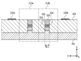
- Figure 5 shows a cross section taken along the cross section line V-V in Figure 4.
- rib type optical waveguides 414a, 414b Near the boundary between high mesa optical waveguide region A, including the connection positions with high mesa optical waveguides 113a, 113b, and high-speed modulation region/rib type optical waveguide region B, rib type optical waveguides 414a, 414b have a wide slab width W414w.
- rib type optical waveguides 414a, 414b near the boundary between high mesa optical waveguide region B, including the connection positions with high mesa optical waveguides 115a, 115b, and high mesa optical waveguide region C, rib type optical waveguides 414a, 414b have a wide slab width W414w.
- the i-type MQW core layer 204, the p-type InP layer 203, and the n-type InP lower cladding layer 202 are located in the range from the separation groove 118 to below the high-frequency lines 120a, 120b.
- the width (y direction) of the high-resistance n-type InP upper cladding layer 205 of the rib-type optical waveguides 414a, 414b is 2 ⁇ m.
- the wide slab width W414w of the i-type MQW core layer 204, p-type InP layer 203, and n-type InP lower cladding layer 202 is 30 ⁇ m.
- the length of the wide slab width W414w in the light propagation direction (x direction) is 100 ⁇ m.
- the thickness of the i-type MQW core layer 204 is 0.5 ⁇ m.
- the fundamental mode of light has a unimodal mode field with maximum intensity at the center of the 2 ⁇ m width of the high-resistance n-type InP upper cladding layer 205.
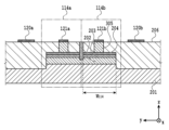
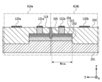
- Figures 6, 7, and 8 show cross sections taken along the lines VI-VI, VII-VII, and VIII-VIII in Figure 4, respectively.
- the rib-type optical waveguides 414a and 414b have a slab width W414n that is narrower than the wide slab width W414w.
- the portions of the rib-type optical waveguides 414a, 414b that are not loaded with the slot electrodes 121a, 121b have a slab width W414n that is narrower than the wide slab width W414w.
- the width (y direction) of the high-resistance n-type InP upper cladding layer 205 of the rib-type optical waveguides 414a, 414b at the position of the cross-sectional line VI-VI in FIG. 4 is 2 ⁇ m.
- the narrow slab width W414n of the i-type MQW core layer 204, the p-type InP layer 203, and the n-type InP lower cladding layer 202 is 13 ⁇ m, which is narrower than the wide width 414 (30 ⁇ m) at the position of the cross-sectional line V-V in FIG. 4 (FIG. 5).
- the thickness of the i-type MQW core layer 204 is 0.5 ⁇ m.
- the fundamental mode of light has a unimodal mode field with maximum intensity at the center of the 2 ⁇ m width of the high-resistance n-type InP upper cladding layer 205.
- the portions of the rib-type optical waveguides 414a, 414b on which the slot electrodes 121a, 121b are loaded have a slab width W414n that is narrower than the wide slab width W414w.
- the portions of the rib-type optical waveguides 414a, 414b have a slab width W414n that is narrower than the wide slab width W414w.
- the width (y direction) of the n-type InP upper cladding layer 305 of the rib-type optical waveguides 414a, 414b is 2 ⁇ m.
- the narrow slab width W414n of the i-type MQW core layer 204, the p-type InP layer 203, and the n-type InP lower cladding layer 202 is 13 ⁇ m, which is narrower than the wide width 414 (30 ⁇ m) at the position of the cross-sectional line V-V in FIG. 4 (FIG. 5).
- the thickness of the i-type MQW core layer 204 is 0.5 ⁇ m.
- the fundamental mode of light has a unimodal mode field with maximum intensity at the center of the 2 ⁇ m width of the n-type InP upper cladding layer 305.
- the rib-type optical waveguides 414a and 414b have a wide slab width W414w at two locations near the boundary between the high-speed modulation region/rib-type optical waveguide region B, which includes the connection positions with the high-mesa optical waveguides 113a, 113b, 115a, and 115b, and the high-mesa optical waveguide regions A and C. The reason for this is explained below.
- the slot electrodes 121a and 121b are not arranged near the boundary side between the high mesa type optical waveguide regions A and C in the high-speed modulation region and rib type optical waveguide region B, an area where the connection electrodes 122a and 122b are not arranged can be secured.
- the i-type MQW core layer 204, p-type InP layer 203, and n-type InP lower cladding layer 202 are not arranged directly below the connection electrodes 122a and 122b.
- connection electrodes 122a and 122b Since high frequency waves also flow in the connection electrodes 122a and 122b, the deterioration of high frequency characteristics is minimized by not providing semiconductors such as the i-type MQW core layer 204, p-type InP layer 203, and n-type InP lower cladding layer 202 directly below the connection electrodes 122a and 122b.
- Figure 9 shows a high-speed optical modulator 900 according to a modified embodiment of the high-speed optical modulator 400 of Figure 4.
- the high-speed modulation region and rib-type optical waveguide region B of the high-speed optical modulator 900 shown in Figure 9 includes rib-type optical waveguides 914a and 914b connected to the high-mesa optical waveguides 113a and 113b and the high-mesa optical waveguides 115a and 115b, respectively.
- each optical waveguide has a tapered shape at the boundary between the two regions to suppress optical connection loss.
- a plurality of slot electrodes 121a and 121b are formed discretely above the rib-type optical waveguides 914a and 914b, respectively, and function as an optical modulator that adds a signal to light by the electro-optic effect.
- the multiple slot electrodes 121a, 121b are connected to the two high-frequency lines 120a, 120b by multiple connection electrodes 122a, 122b, respectively.
- the two high-frequency lines 120a, 120b are formed parallel to the rib-type optical waveguides 914a, 914b above the organic film (e.g., BCB) 206, which is a non-semiconductor material, in order to propagate the RF modulated electrical signal with low loss.
- the multiple connection electrodes 122a, 122b are formed perpendicular to the rib-type optical waveguides 414a, 414b.
- the layer structure of the InP semiconductor of the rib-type optical waveguides 414a and 414b is similar to the layer structure of the InP semiconductor of the rib-type optical waveguides 114a and 114b described with reference to FIG. 3.
- the rib-type optical waveguides 914a, 914b have a wide width not only near the boundary between the high-mesa optical waveguide region A, which includes the connection positions with the high-mesa optical waveguides 113a, 113b, and the high-speed modulation region/rib-type optical waveguide region B, but also between the multiple connection electrodes 122a, 122b arranged in the light propagation direction within the high-speed modulation region/rib-type optical waveguide region B.
- a portion of the rib-type optical waveguide in the high-speed modulation region and rib-type optical waveguide region B is made wide (e.g., 30 ⁇ m), and the remaining portion is made narrow (e.g., 13 ⁇ m).
- This is equivalent to a configuration in which slab waveguides of different widths are connected in series.
- the shape and effective refractive index of the higher-order mode when the core width in the optical waveguide is 13 ⁇ m differs from that of the higher-order mode when the core width is 30 ⁇ m, so mode mismatch occurs at the connection point of the slab waveguide, resulting in loss.
- the fundamental mode which is the main mode
- the fundamental mode is confined to the upper cladding width of about 2 ⁇ m, so it propagates without feeling the width of the slab waveguide, such as 13 ⁇ m or 30 ⁇ m, and is therefore less affected.
- the higher-order mode is removed, and deterioration of the extinction ratio is suppressed.
- the i-type MQW core layer 204, p-type InP layer 203, and n-type InP lower cladding layer 202 are formed below the high-frequency lines 120a, 120b parallel to the rib-type optical waveguides 414a, 414b, the high-frequency characteristics will deteriorate.
- the length of the rib-type optical waveguides 414a, 414b with the wide slab width W414w in the light propagation direction (x direction) is short (for example, 100 ⁇ m), and the deterioration of the high-frequency characteristics is also limited.
- the rib-type optical waveguides 414a, 414b have two different widths (W414w and W414n), but it goes without saying that the same effect can be obtained even if the rib-type optical waveguides 414a, 414b have three or more different widths.
- High-speed phase modulator 111 High mesa type optical waveguide 112 1 ⁇ 2 demultiplexer 113a, 113b High mesa type optical waveguide 114a, 114b, 414a, 414b, 914a, 914b Rib type optical waveguide 115a, 115b High mesa type optical waveguide 116 2 ⁇ 1 multiplexer 117 High mesa type optical waveguide 118 Separation groove 120a, 120b High frequency line 121a, 121b Slot electrode 122a, 122b Connection electrode 130a, 130b Thin film heater 131a, 131b Pad 132a, 132b Wiring 150a, 150b Termination resistor 201 Semi-insulating InP substrate 202 n-type InP lower cladding layer 203 p-type InP layer 204 i-type MQW core layer 205 high-resistance InP upper cladding layer 206 organic film (BCB) 305 High resistance InP upper cladding layer 400, 900 High speed optical modulator
Landscapes
- Physics & Mathematics (AREA)
- General Physics & Mathematics (AREA)
- Optics & Photonics (AREA)
- Engineering & Computer Science (AREA)
- Microelectronics & Electronic Packaging (AREA)
- Nonlinear Science (AREA)
- Optical Modulation, Optical Deflection, Nonlinear Optics, Optical Demodulation, Optical Logic Elements (AREA)
Abstract
L'invention concerne un modulateur optique à grande vitesse ayant d'excellentes propriétés optiques. Le modulateur optique comprend deux guides d'ondes optiques de bras connectés à un démultiplexeur (112), qui a une structure de guide d'ondes optique de type mesa élevé qui est connectée à un premier guide d'ondes optique de type mesa élevé (111), et un multiplexeur (116), qui a une structure de guide d'ondes optique de type mesa élevé qui est connectée à un second guide d'ondes optique de type mesa élevé (117). Les guides d'ondes optiques de bras sont chacun pourvus d'un guide d'ondes optique de type mesa élevé (113a, 113b), d'un guide d'ondes optique de type nervure (414a, 414b), d'un guide d'ondes optique de type mesa élevé (115a, 115b), et d'une électrode (121a, 121b) disposée sur le guide d'ondes optique de type nervure. Chaque guide d'ondes optique de type nervure (414a, 414b) comprend une couche de gainage inférieure (202), une couche centrale (204) et une couche de gainage supérieure (205) dans cet ordre sur un substrat (201). Dans une section transversale orthogonale à la direction de propagation de la lumière, la largeur de la couche de gainage supérieure est inférieure aux largeurs de la couche centrale et de la couche de gainage inférieure, et les largeurs de la couche centrale et de la couche de gainage inférieure comprennent deux largeurs ou plus, comprenant une première largeur (W414n) et une seconde largeur (W414w) qui est supérieure à la première largeur.
Priority Applications (2)
| Application Number | Priority Date | Filing Date | Title |
|---|---|---|---|
| JP2025525504A JPWO2024252534A1 (fr) | 2023-06-06 | 2023-06-06 | |
| PCT/JP2023/021061 WO2024252534A1 (fr) | 2023-06-06 | 2023-06-06 | Modulateur optique |
Applications Claiming Priority (1)
| Application Number | Priority Date | Filing Date | Title |
|---|---|---|---|
| PCT/JP2023/021061 WO2024252534A1 (fr) | 2023-06-06 | 2023-06-06 | Modulateur optique |
Publications (1)
| Publication Number | Publication Date |
|---|---|
| WO2024252534A1 true WO2024252534A1 (fr) | 2024-12-12 |
Family
ID=93795481
Family Applications (1)
| Application Number | Title | Priority Date | Filing Date |
|---|---|---|---|
| PCT/JP2023/021061 Ceased WO2024252534A1 (fr) | 2023-06-06 | 2023-06-06 | Modulateur optique |
Country Status (2)
| Country | Link |
|---|---|
| JP (1) | JPWO2024252534A1 (fr) |
| WO (1) | WO2024252534A1 (fr) |
Citations (5)
| Publication number | Priority date | Publication date | Assignee | Title |
|---|---|---|---|---|
| JPH063708A (ja) * | 1992-06-19 | 1994-01-14 | Nippon Telegr & Teleph Corp <Ntt> | 光スイッチとその製造方法 |
| US20030039447A1 (en) * | 2001-08-27 | 2003-02-27 | Clapp Terry V. | Strip-loaded optical waveguide |
| WO2010100946A1 (fr) * | 2009-03-05 | 2010-09-10 | 日本電気株式会社 | Modulateur optique semi-conducteur, dispositif intégré optique semi-conducteur et leur procédé de fabrication |
| WO2019156189A1 (fr) * | 2018-02-08 | 2019-08-15 | 古河電気工業株式会社 | Élément optique intégré et module optique |
| WO2019211991A1 (fr) * | 2018-05-01 | 2019-11-07 | 日本電信電話株式会社 | Modulateur optique de mach-zehnder à semi-conducteur et modulateur optique iq l'utilisant |
-
2023
- 2023-06-06 JP JP2025525504A patent/JPWO2024252534A1/ja active Pending
- 2023-06-06 WO PCT/JP2023/021061 patent/WO2024252534A1/fr not_active Ceased
Patent Citations (5)
| Publication number | Priority date | Publication date | Assignee | Title |
|---|---|---|---|---|
| JPH063708A (ja) * | 1992-06-19 | 1994-01-14 | Nippon Telegr & Teleph Corp <Ntt> | 光スイッチとその製造方法 |
| US20030039447A1 (en) * | 2001-08-27 | 2003-02-27 | Clapp Terry V. | Strip-loaded optical waveguide |
| WO2010100946A1 (fr) * | 2009-03-05 | 2010-09-10 | 日本電気株式会社 | Modulateur optique semi-conducteur, dispositif intégré optique semi-conducteur et leur procédé de fabrication |
| WO2019156189A1 (fr) * | 2018-02-08 | 2019-08-15 | 古河電気工業株式会社 | Élément optique intégré et module optique |
| WO2019211991A1 (fr) * | 2018-05-01 | 2019-11-07 | 日本電信電話株式会社 | Modulateur optique de mach-zehnder à semi-conducteur et modulateur optique iq l'utilisant |
Also Published As
| Publication number | Publication date |
|---|---|
| JPWO2024252534A1 (fr) | 2024-12-12 |
Similar Documents
| Publication | Publication Date | Title |
|---|---|---|
| US8412008B2 (en) | Semiconductor optical device | |
| US8412005B2 (en) | Mach-Zehnder interferometer type optical modulator | |
| US11275287B2 (en) | Semiconductor Mach-Zehnder optical modulator and IQ optical modulator using same | |
| US10027088B2 (en) | Integrated semiconductor optical element and manufacturing method for same | |
| EP4369082A1 (fr) | Modulateur électro-optique et dispositif électro-optique | |
| US20030091287A1 (en) | Multimode interference (MMI) device | |
| JP6126541B2 (ja) | 半導体マッハツェンダ光変調器 | |
| EP3913425B1 (fr) | Modulateur optique de mach-zehnder à semi-conducteur | |
| JP7356050B2 (ja) | 光スイッチ装置 | |
| JP5917645B2 (ja) | 光スイッチ素子 | |
| JP6348880B2 (ja) | 半導体マッハツェンダ光変調器 | |
| CA3153651C (fr) | Modulateur optique de mach-zehnder a semi-conducteur et modulateur optique iq | |
| WO2024252534A1 (fr) | Modulateur optique | |
| JP2019045666A (ja) | 半導体マッハツェンダ光変調器およびiq変調器 | |
| JP2014191218A (ja) | 光変調器 | |
| WO2019235392A1 (fr) | Dispositif de commutation optique | |
| US20220091472A1 (en) | Optical Switch Element | |
| JP2007094336A (ja) | 光半導体素子および光半導体素子の製造方法 | |
| JP2016114712A (ja) | 半導体マッハツェンダー光変調器 | |
| WO2019176665A1 (fr) | Modulateur optique | |
| JP2011133582A (ja) | 半導体マッハツェンダ型光変調器および半導体マッハツェンダ型光変調器の製造方法 | |
| JP6023028B2 (ja) | 光スイッチ素子 | |
| JP2014191085A (ja) | 光変調器 | |
| JP4209357B2 (ja) | 半導体光変調器 | |
| WO2024247046A1 (fr) | Modulateur optique |
Legal Events
| Date | Code | Title | Description |
|---|---|---|---|
| 121 | Ep: the epo has been informed by wipo that ep was designated in this application |
Ref document number: 23940639 Country of ref document: EP Kind code of ref document: A1 |
|
| ENP | Entry into the national phase |
Ref document number: 2025525504 Country of ref document: JP Kind code of ref document: A |
|
| NENP | Non-entry into the national phase |
Ref country code: DE |