WO2024252571A1 - 回転電機 - Google Patents
回転電機 Download PDFInfo
- Publication number
- WO2024252571A1 WO2024252571A1 PCT/JP2023/021195 JP2023021195W WO2024252571A1 WO 2024252571 A1 WO2024252571 A1 WO 2024252571A1 JP 2023021195 W JP2023021195 W JP 2023021195W WO 2024252571 A1 WO2024252571 A1 WO 2024252571A1
- Authority
- WO
- WIPO (PCT)
- Prior art keywords
- frame
- electric machine
- rotor
- rotating electric
- cooling fan
- Prior art date
- Legal status (The legal status is an assumption and is not a legal conclusion. Google has not performed a legal analysis and makes no representation as to the accuracy of the status listed.)
- Ceased
Links
Images


Classifications
-
- H—ELECTRICITY
- H02—GENERATION; CONVERSION OR DISTRIBUTION OF ELECTRIC POWER
- H02K—DYNAMO-ELECTRIC MACHINES
- H02K9/00—Arrangements for cooling or ventilating
- H02K9/02—Arrangements for cooling or ventilating by ambient air flowing through the machine
- H02K9/04—Arrangements for cooling or ventilating by ambient air flowing through the machine having means for generating a flow of cooling medium
- H02K9/06—Arrangements for cooling or ventilating by ambient air flowing through the machine having means for generating a flow of cooling medium with fans or impellers driven by the machine shaft
Definitions
- This disclosure relates to rotating electrical machines.
- cooling fans are installed on the outside of the frame that surrounds the stator, and the rotating electric machine is cooled by forced air convection using the cooling fans.
- the conventional structure when the amount of heat generated by the rotating electric machine increases, the temperature of the air inside the frame rises, and because the heat transfer area between the frame and the air is small, there is an issue that the heat cannot be sufficiently dissipated. Therefore, with the conventional structure, when the rotation speed of the rotor increases and the amount of heat generated inside the rotating electric machine increases, the number of cooling fans must be increased or cooling fans that can circulate a large amount of air must be installed, which can lead to an increase in the overall size of the rotating electric machine, including the heat dissipation system.
- This disclosure has been made in consideration of the above, and aims to provide a rotating electric machine that has high heat dissipation capabilities as well as being small and lightweight.
- the rotating electric machine has a frame, a rotor disposed inside the frame and rotating, a stator disposed inside the frame, a cooling fan disposed outside the frame, and multiple external fins provided on the outer peripheral surface of the frame.
- An internal air circulation flow path is provided between the frame and the stator to circulate air inside the frame in the direction of the rotation axis of the rotor.
- the air flow path formed by the multiple external fins intersects with the internal air circulation flow path.
- the rotor is surrounded by the stator and has a shaft that serves as the rotation axis, end plates that adjust the rotation balance of the rotor, and internal fins that are provided on the end plates and circulate air inside the frame.
- the rotating electric machine disclosed herein has the advantage of being small and lightweight while also having high heat dissipation capabilities.
- FIG. 1 is a first cross-sectional view of a rotating electric machine according to a first embodiment
- FIG. 2 is a second cross-sectional view of the rotating electric machine according to the first embodiment
- FIG. 1 is a perspective view showing a main portion of a frame of a rotating electric machine according to a first embodiment
- FIG. 13 is a diagram showing a state in which the inside air circulation flow path and a plurality of outer fins are perpendicular to each other in the first embodiment
- FIG. 13 is a diagram showing a state in which a plurality of outer fins are inclined with respect to the inside air circulation flow path in the first embodiment
- FIG. 13 is a perspective view showing a main portion of a frame of a rotating electric machine according to a second embodiment
- FIG. 13 is a perspective view showing a first modified example of a main portion of a frame of a rotating electric machine according to a second embodiment
- FIG. 13 is a perspective view showing a second modified example of a main portion of a frame of a rotating electric machine according to a second embodiment
- FIG. 13 is a perspective view showing the appearance of a rotating electric machine according to a third embodiment.
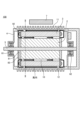
- FIG. 1 is a first cross-sectional view of the rotating electric machine 100 according to the first embodiment.
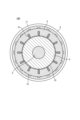
- FIG. 2 is a second cross-sectional view of the rotating electric machine 100 according to the first embodiment.
- FIG. 2 shows a main part in the II-II plane of FIG. 1.
- FIG. 1 and FIG. 2 show a schematic cross-section of the rotating electric machine 100.
- the rotating electric machine 100 has a rotor 2, a stator 3, a frame 4, and a cooling fan 7.
- the rotor 2 is disposed inside the frame 4 and rotates.
- the stator 3 is disposed inside the frame 4.
- the rotor 2 is surrounded by the stator 3.
- the cooling fan 7 is disposed outside the frame 4.
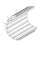
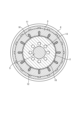
- FIG. 3 is a perspective view showing a main part of the frame 4 of the rotating electric machine 100 according to the first embodiment.
- FIG. 3 shows a schematic view of a main part of the frame 4.
- the rotor 2 has a shaft 5 that serves as the axis of rotation, and an end plate 81 that adjusts the rotational balance of the rotor 2.
- the shaft 5 is disposed so as to pass through the rotor 2, and is rotatably supported by a load side bearing 61 disposed on the load side of the frame 4, and an anti-load side bearing 62 disposed on the anti-load side.
- the direction in which the shaft 5 extends is also referred to as the axial direction.
- the stator 3 is cylindrical and has a coil 91 inside. A portion of the coil 91 protrudes outside the stator 3 as a coil end 92.
- the stator 3 is disposed so as to surround the rotor 2, and an air gap 10 exists between the stator 3 and the rotor 2.
- the central axis of the stator 3 is the same as the rotation axis of the rotor 2.
- the frame 4 is cylindrical, and the stator 3 is disposed inside the frame 4. Between the frame 4 and the stator 3, an internal air circulation flow path 12 is provided for circulating air inside the frame 4 in the axial direction.
- the axial direction is the direction in which the shaft 5 extends. More specifically, the axial direction is the direction of the rotation axis of the rotor 2.
- an external fin 11 is provided that is configured to be integrated with the frame 4. As shown in FIG. 1, a plurality of external fins 11 are disposed at intervals from each other in the axial direction. As shown in FIG. 2, for example, the external fin 11 is provided so as to go around the outer periphery of the cylindrical frame 4.
- FIG. 3 also shows the internal air circulation flow path 12 and the external fin 11.
- the cooling fan 7 is installed outside the frame 4 to send air to the outer fins 11. More specifically, the cooling fan 7 is installed outside the frame 4 at a position facing the circumferential side of the frame 4. The air blown out from the cooling fan 7 flows in the circumferential direction of the frame 4 through a flow path formed by the outer fins 11 provided on the outer peripheral surface of the frame 4. As a result, the air blown out from the cooling fan 7 dissipates the heat transferred to the frame 4 to the outside of the frame 4.
- the air flow path formed by the multiple outer fins 11 intersects with the internal air circulation flow path 12, preferably at right angles.
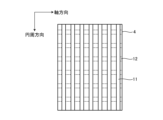
- Figure 4 is a diagram showing a state in which the internal air circulation flow path 12 and the multiple outer fins 11 are perpendicular to each other in the first embodiment.
- Figure 5 is a diagram showing a state in which the multiple outer fins 11 are inclined with respect to the internal air circulation flow path 12 in the first embodiment.
- the end plate 81 is disposed so that it penetrates the shaft 5, and rotates in accordance with the rotation of the rotor 2.
- the rotor 2 further has inner fins 82 provided on the end plate 81.
- the inner fins 82 are components that circulate the air inside the frame 4. When the end plate 81 rotates, the inner fins 82 also rotate, and the inner fins 82 agitate the air inside the frame 4. In FIG. 1, the direction of the agitated air is indicated by an arrow.
- the air inside the frame 4 is prevented from intermingling with the air blown out from the cooling fan 7 by the frame 4.
- the rotating electric machine 100 When the rotating electric machine 100 is operated, the rotor 2 rotates to operate a device installed on the load side at a desired rotational speed. This device is not shown.
- the cooling fan 7 installed on the outside of the frame 4 operates, and air flows in the circumferential direction of the frame 4 to cool the frame 4. As the air flows in the circumferential direction of the frame 4, heat generated by the rotating electric machine 100 dissipates, and the rotating electric machine 100 is cooled.
- the end plate 81 rotates in accordance with the rotation of the rotor 2, and the rotation of the end plate 81 rotates the inner fin 82, which then agitates the air inside the frame 4.
- the air agitated by the inner fin 82 flows through the air gap 10, and heat is transferred to the agitated air from the rotor 2 and the stator 3.
- the agitated air flows through the internal air circulation flow path 12 provided between the stator 3 and the frame 4, and heat is transferred to the agitated air from the stator 3 and the coil end 92.
- the rotating electric machine 100 can transfer the heat of the air whose temperature has increased inside the frame 4 to the frame 4.
- the heat transferred to the frame 4 is cooled by the cooling fan 7 and the outer fins 11. That is, the cooling fan 7 and the outer fins 11 cool the stator 3 and the air flowing through the internal air circulation flow path 12.
- the rotating electric machine 100 can cool the rotor 2 that is not in contact with the frame 4.
- the rotating electric machine 100 can prevent electrical malfunctions and deterioration caused by the rotor 2 becoming too hot.
- the inner fins 82 provided on the end plate 81 that rotates together with the rotor 2 stir the air inside the frame 4, and the stirred air circulates through the air gap 10 and the internal air circulation flow path 12, so that the rotating electric machine 100 transfers the heat of the rotor 2 to the outer fins 11 provided on the frame 4 via the frame 4, and dissipates it to the outside air by the cooling fan 7.
- the rotor 2 can be cooled without installing the cooling fan 7 in the axial direction, and therefore the axial size is suppressed.
- the rotor 2 may be provided with an internal rotor ventilation passage 13 that penetrates in the axial direction. This allows the air inside the frame 4 to circulate inside the rotor 2 as well, so that the rotor 2 can be cooled effectively.
- FIG. 6 is a schematic diagram showing a configuration in which the rotor 2 is provided with an internal rotor ventilation passage 13 that penetrates in the axial direction in the first embodiment.
- the number of internal air circulation passages 12 is 16, but the number of internal air circulation passages 12 can be any number.
- the number of internal rotor ventilation passages 13 is 8, but the number of internal rotor ventilation passages 13 can be any number.
- Embodiment 2 In the following embodiments, the same reference numerals as those in FIGS. 1 to 6 denote the same or similar components, and detailed description of the same or similar components will be omitted.
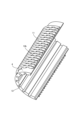
- FIG. 7 is a perspective view showing a main part of the frame 4 of the rotating electric machine 200 according to the second embodiment.
- FIG. 7 shows a schematic of the main part of the frame 4.
- the outer fins 11 are formed with circular ventilation holes 14 in the axial direction so that air can flow in the axial direction.
- the ventilation holes 14 are shown enlarged.
- the axial direction is the direction of the rotation axis of the rotor 2.
- the configuration of the rotating electric machine 200 other than the outer fins 11 is the same as that of the first embodiment.
- the outer fins 11 are formed with ventilation holes 14, the air blown out from the cooling fan 7 flows around the entire outer periphery of the frame 4, in comparison with the first embodiment. This allows the rotating electric machine 200 to efficiently transfer heat from the frame 4 to the outside air.
- the rotating electric machine 200 can efficiently transfer heat transferred to the frame 4 from the high-temperature air flowing through the internal air circulation flow path 12 to the air outside the frame 4. Therefore, the rotating electric machine 200 can suppress the rotor 2 from becoming too hot.
- the outer fin 11 has a circular ventilation hole 14, but the shape of the ventilation hole 14 is not limited to a circular shape.
- a rectangular ventilation hole 14a may be formed at the base portion of the outer fin 11.
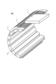
- FIG. 8 is a perspective view showing a first modified example of a main portion of the frame 4 of the rotating electric machine 200 according to the second embodiment.
- FIG. 8 shows a schematic diagram of the first modified example of the main portion of the frame 4.
- the ventilation hole 14a is shown enlarged.
- the base portion is the portion where the outer fin 11 contacts the outer peripheral surface of the frame 4.
- FIG. 9 is a perspective view showing a second modification of the main part of the frame 4 of the rotating electric machine 200 according to the second embodiment.
- FIG. 9 shows a schematic diagram of the second modification of the main part of the frame 4.
- the rotating electric machine 300 according to the third embodiment has all of the components included in the rotating electric machine 100 according to the first embodiment.
- Fig. 10 is a perspective view showing the appearance of the rotating electric machine 300 according to the third embodiment.
- Fig. 10 shows a schematic view of the appearance of the rotating electric machine 300.
- the rotating electric machine 300 further has a flow path cover 15 provided on the outside of the frame 4.
- the flow path cover 15 covers the outer fins 11. More specifically, the flow path cover 15 covers the tip portion of the outer fins 11. The tip portion of the outer fins 11 is the portion opposite the portion of the outer fins 11 that contacts the frame 4. The flow path cover 15 covers the outer fins 11 except for the portion facing the cooling fan 7 of the frame 4, and is formed so that the air blown out from the cooling fan 7 flows in the entire circumferential direction on the outside of the frame 4.
- the configuration of the rotating electric machine 300 other than the flow path cover 15 is the same as the configuration of embodiment 1.
- the rotating electric machine 300 has a flow path cover 15 that allows the air blown out from the cooling fan 7 to flow around the entire circumference of the frame 4, so the frame 4 can be cooled efficiently.
- the temperature difference that occurs around the circumference of the stator 3 can be reduced, making it possible to suppress the need to increase the size or add additional cooling fans 7 due to insufficient cooling capacity, and to prevent the rotating electric machine 300 from becoming larger.
- the outer fin 11 of embodiment 3 may have the ventilation holes 14, 14a, or 14b of embodiment 2 formed therein.
- the rotating electric machine 400 according to the fourth embodiment has all the components of the rotating electric machine 100 according to the first embodiment.
- FIG. 11 is a perspective view showing the appearance of the rotating electric machine 400 according to the fourth embodiment.
- FIG. 11 shows a schematic view of the appearance of the rotating electric machine 400.
- the outer fins 11 are provided on the outer peripheral surface of the frame 4 so that the heat transfer area increases as the air blown out from the cooling fan 7 moves downstream.
- the outer fins 11 are configured so that the heat transfer area is small in the vicinity of the cooling fan 7, and the heat transfer area increases as the air blown out from the cooling fan 7 flows downstream.
- the configuration of the rotating electric machine 400 other than the outer fins 11 is the same as the configuration of the first embodiment.
- the air blown out from the cooling fan 7 has a high heat dissipation capacity due to the turbulence of the air flow near the outlet of the cooling fan 7, but as it flows between the outer fins 11 attached to the outer peripheral surface of the frame 4, the flow is straightened and the heat dissipation capacity of the air blown out from the cooling fan 7 decreases. For this reason, by making the heat transfer area of the outer fins 11 small near the outlet of the cooling fan 7 and increasing the heat transfer area downstream, it is possible to achieve a uniform cooling effect in the circumferential direction.
- the rotating electric machine 400 has outer fins 11 provided on the outer periphery of the frame 4 so that the heat transfer area increases as the air blown out from the cooling fan 7 moves downstream.
- the outer fins 11 allow the rotating electric machine 400 to be cooled efficiently, and in turn, the temperature of the stator 3 can be made uniform, making it possible to prevent electrical malfunctions and deterioration of the stator 3 caused by the occurrence of localized high temperature spots.
- one way to increase the heat transfer area of the outer fins 11 provided on the outer peripheral surface of the frame 4 is to increase the height of the outer fins 11.
- the height of the outer fins 11 located relatively close to the cooling fan 7 is made lower than the height of the outer fins 11 located relatively far from the cooling fan 7.
- Another way to increase the heat transfer area of the outer fins 11 provided on the outer peripheral surface of the frame 4 is to increase the axial thickness of the outer fins 11.
- an outer fin 11 may be additionally installed in the axial direction downstream of the air blown out from the cooling fan 7.
- outer fin 11 of embodiment 4 may be formed with the ventilation holes 14, 14a, or 14b of embodiment 2.
- FIG. 12 is a cross-sectional view of a rotating electric machine 500 according to the fifth embodiment.
- Fig. 12 shows a schematic cross-section of the rotating electric machine 500.
- the rotating electric machine 500 has all the components of the rotating electric machine 100 according to the first embodiment.
- the rotating electric machine 500 further has a second cooling fan 7a disposed outside the frame 4. That is, the rotating electric machine 500 has two cooling fans.
- the second cooling fan 7a faces the cooling fan 7 across the frame 4.
- the configuration of the rotating electric machine 500 other than the second cooling fan 7a is the same as the configuration of the first embodiment.
- the air blown out from the cooling fan 7 flows in the circumferential direction of the frame 4, and the air blown out from the second cooling fan 7a also flows in the circumferential direction of the frame 4.
- the cooling fan 7 and the second cooling fan 7a are positioned opposite each other, the air blown out from the cooling fan 7 and the air blown out from the second cooling fan 7a can flow in the circumferential direction of the frame 4 without interfering with each other. Therefore, the volume of air blown out from one cooling fan can be reduced by more than half.
- the arrows show the direction in which the air blown out from the cooling fan 7 and the air blown out from the second cooling fan 7a flow.
- the rotating electric machine 500 can reduce the amount of heat dissipated by one cooling fan, making it possible to miniaturize the cooling fan 7 and the second cooling fan 7a. Therefore, since the amount of air blown out from each of the cooling fan 7 and the second cooling fan 7a can be reduced, the rotating electric machine 500 can reduce the noise generated by the cooling fan 7 and the second cooling fan 7a.
Landscapes
- Engineering & Computer Science (AREA)
- Power Engineering (AREA)
- Motor Or Generator Cooling System (AREA)
- Motor Or Generator Frames (AREA)
Abstract
回転電機(100)は、フレーム(4)と、フレーム(4)の内部に配置されていて回転する回転子(2)と、フレーム(4)の内部に配置されている固定子(3)と、フレーム(4)の外部に配置されている冷却ファン(7)と、フレーム(4)の外周面に設けられている複数の外側フィン(11)とを有する。フレーム(4)と固定子(3)との間にはフレーム(4)の内側の空気を回転子(2)の回転軸の方向に流通させるための内気循環流路(12)が設けられている。複数の外側フィン(11)が形成する空気の流路は、内気循環流路(12)と交差している。回転子(2)は、固定子(3)に囲われていて、回転軸となるシャフト(5)と、回転子(2)の回転バランスを調整するエンドプレート(81)と、エンドプレート(81)に設けられていてフレーム(4)の内側の空気を循環させる内側フィン(82)とを有する。
Description
本開示は、回転電機に関する。
従来の回転電機では、高速回転及び高負荷駆動の状態で長時間使用すると、温度が上昇し、モータ性能の低下及びモータの故障等が発生し、更には回転電機が組み込まれている機器の運転を停止しなければならないという事態も生じかねない。そのため、従来から、回転電機で発生した熱を冷却ファンによって放散させる方法が採用されている(例えば特許文献1)。
従来、固定子を囲むフレームの外側に冷却ファンを設置して冷却ファンによる空気の強制対流で回転電機を冷却する。しかし、従来の構造では回転電機の発熱量が増加した場合、フレームの内部の空気の温度が上昇し、フレームと空気との伝熱面積が小さいので熱を十分に逃がすことができないという課題が生じる。そのため、従来の構造では、回転子の回転速度が増加して回転電機の内部の発熱量が増加した場合、冷却ファンの個数を増加する又は大量の空気を通流させられる冷却ファンを設置することになるため、放熱系を含めた回転電機の全体の大型化を招き得る。
本開示は、上記に鑑みてなされたものであって、高い放熱能力を有するとともに小型でかつ軽量な回転電機を得ることを目的とする。
上述した課題を解決し、目的を達成するために、本開示に係る回転電機は、フレームと、フレームの内部に配置されていて回転する回転子と、フレームの内部に配置されている固定子と、フレームの外部に配置されている冷却ファンと、フレームの外周面に設けられている複数の外側フィンとを有する。フレームと固定子との間にはフレームの内側の空気を回転子の回転軸の方向に流通させるための内気循環流路が設けられている。複数の外側フィンが形成する空気の流路は、内気循環流路と交差している。回転子は、固定子に囲われていて、回転軸となるシャフトと、回転子の回転バランスを調整するエンドプレートと、エンドプレートに設けられていてフレームの内側の空気を循環させる内側フィンとを有する。
本開示に係る回転電機は、高い放熱能力を有するとともに小型でかつ軽量であるという効果を奏する。
以下に、実施の形態に係る回転電機を図面に基づいて詳細に説明する。
実施の形態1.
図1は、実施の形態1に係る回転電機100の第1の断面図である。図2は、実施の形態1に係る回転電機100の第2の断面図である。図2は、図1のII-II面における要部を示している。図1及び図2は、回転電機100の断面を模式的に示している。回転電機100は、回転子2と、固定子3と、フレーム4と、冷却ファン7とを有する。回転子2は、フレーム4の内部に配置されていて回転する。固定子3は、フレーム4の内部に配置されている。回転子2は、固定子3に囲われている。冷却ファン7は、フレーム4の外部に配置されている。図3は、実施の形態1に係る回転電機100が有するフレーム4の要部を示す斜視図である。図3は、フレーム4の要部を模式的に示している。
図1は、実施の形態1に係る回転電機100の第1の断面図である。図2は、実施の形態1に係る回転電機100の第2の断面図である。図2は、図1のII-II面における要部を示している。図1及び図2は、回転電機100の断面を模式的に示している。回転電機100は、回転子2と、固定子3と、フレーム4と、冷却ファン7とを有する。回転子2は、フレーム4の内部に配置されていて回転する。固定子3は、フレーム4の内部に配置されている。回転子2は、固定子3に囲われている。冷却ファン7は、フレーム4の外部に配置されている。図3は、実施の形態1に係る回転電機100が有するフレーム4の要部を示す斜視図である。図3は、フレーム4の要部を模式的に示している。
回転子2は、回転軸となるシャフト5と、回転子2の回転バランスを調整するエンドプレート81とを有する。シャフト5は、回転子2を貫通して配置されており、フレーム4の負荷側に配置されている負荷側ベアリング61と反負荷側に配置されている反負荷側ベアリング62とによって回転自在に支持される。以下、シャフト5が延伸する方向を軸方向ともいう。
固定子3は、筒状に構成されており、内部にコイル91を有する。コイル91の一部は、コイルエンド92として固定子3の外部に突出している。固定子3は、回転子2を囲うように配置され、固定子3と回転子2との間にはエアギャップ10が存在している。固定子3の中心軸は、回転子2の回転軸と同じである。
フレーム4は筒状に構成されており、フレーム4の内側に固定子3が配置されている。フレーム4と固定子3との間には、フレーム4の内側の空気を軸方向に流通させるための内気循環流路12が設けられている。上述の通り、軸方向は、シャフト5が延伸する方向である。更に言うと、軸方向は、回転子2の回転軸の方向である。フレーム4の外周面には、フレーム4と一体になるように構成された外側フィン11が立設されている。図1に示されるように、外側フィン11は、軸方向に互いに間隔を空けて複数配置されている。図2に示されるように、例えば、外側フィン11は、円筒状のフレーム4の外周を一周するように設けられる。図3には、内気循環流路12及び外側フィン11も示されている。
冷却ファン7は、外側フィン11に空気を送るためにフレーム4の外側に設置される。更に言うと、冷却ファン7は、フレーム4の外側においてフレーム4の周方向の側面と対向する位置に設置される。冷却ファン7から吹き出される空気は、フレーム4の外周面に設けられた外側フィン11によって構成された流路をフレーム4の周方向に流れる。これにより、冷却ファン7から吹き出された空気は、フレーム4に伝わった熱をフレーム4の外部に放散させる。複数の外側フィン11が形成する空気の流路は、内気循環流路12と交差、望ましくは直交している。図4は、実施の形態1において内気循環流路12と複数の外側フィン11とが直交している状態を示す図である。図5は、実施の形態1において複数の外側フィン11が内気循環流路12に対して傾斜している状態を示す図である。
エンドプレート81は、シャフト5に貫通されて配置されており、回転子2の回転に合わせて回転する。回転子2は、エンドプレート81に設けられている内側フィン82を更に有する。内側フィン82は、フレーム4の内側の空気を循環させる構成要素である。エンドプレート81が回転すると、内側フィン82も回転し、内側フィン82はフレーム4の内部の空気を撹拌する。図1には、攪拌された空気の向きが矢印で示されている。フレーム4の内部の空気は、フレーム4により、冷却ファン7から吹き出され空気と交わることはない。
次に、実施の形態1に係る回転電機100の動作を説明する。回転電機100が運転されると、回転子2が回転して負荷側に設置された装置を所望の回転速度で動作させる。当該装置は、図示されていない。フレーム4の外側に設置された冷却ファン7が動作し、フレーム4の周方向にフレーム4を冷却するための空気が流れる。フレーム4の周方向に空気が流れることにより回転電機100から発生される熱が放散し、回転電機100は冷却される。
この時、回転子2の回転に合わせてエンドプレート81が回転し、エンドプレート81の回転により内側フィン82が回転し、内側フィン82はフレーム4の内部の空気を撹拌する。内側フィン82によって撹拌された空気がエアギャップ10を通流し、当該撹拌された空気に回転子2及び固定子3からの熱が伝わる。当該撹拌された空気は、固定子3とフレーム4との間に設けられた内気循環流路12を通流し、当該撹拌された空気に固定子3及びコイルエンド92からの熱が伝わる。
フレーム4の内部で空気が内気循環流路12を通流することで、回転電機100は、フレーム4の内部で温度が上昇した空気の熱をフレーム4に伝えることができる。フレーム4に伝わった熱は、冷却ファン7と外側フィン11とにより冷却される。すなわち、冷却ファン7と外側フィン11とが、固定子3と内気循環流路12を通流する空気とを冷却する。ひいては、回転電機100は、フレーム4に接していない回転子2を冷却することができる。その結果、回転電機100は、回転子2が高温化することによる電気的な不具合及び劣化を防ぐことができる。
このように、回転子2と合わせて回転するエンドプレート81に設けられた内側フィン82がフレーム4の内部の空気を攪拌し、攪拌された空気がエアギャップ10及び内気循環流路12を循環することで、回転電機100は、回転子2の熱を、フレーム4を介してフレーム4に設けられた外側フィン11に伝え、冷却ファン7によって外気に放散させる。これにより、回転子2を効果的に冷却することができるため、冷却ファン7の大型化及び増設による回転電機100の全体の大型化が抑制される。さらに、複数の外側フィン11が形成する空気の流路を内気循環流路12と交差するように構成することで、冷却ファン7を軸方向に設置せずに回転子2を冷却できるようになるため、軸方向の大型化が抑制される。すなわち、実施の形態1によれば、高い放熱能力を有するとともに小型でかつ軽量な回転電機100を得ることができる。
回転子2を冷却する効果を高めるために、図6に示されるように、回転子2に、軸方向に貫通する回転子内通風路13が設けられてもよい。これにより、回転子2の内側もフレーム4の内側の空気が循環することになるため、回転子2を効果的に冷却することができる。図6は、実施の形態1において軸方向に貫通する回転子内通風路13が回転子2に設けられた構成を模式的に示す図である。
なお、図2では内気循環流路12の本数は16本であるが、内気循環流路12の本数は何本でも構わない。さらに、図6では回転子内通風路13の本数は8本であるが、回転子内通風路13の本数は何本でも構わない。
実施の形態2.
以下の実施の形態において、図1から図6までの参照符号と同一の符号は、同一又は同様の構成要素を示すので、同一又は同様の構成要素の詳細な説明は省略する。
以下の実施の形態において、図1から図6までの参照符号と同一の符号は、同一又は同様の構成要素を示すので、同一又は同様の構成要素の詳細な説明は省略する。
実施の形態2に係る回転電機200は、実施の形態1に係る回転電機100が有するすべての構成要素を有する。図7は、実施の形態2に係る回転電機200が有するフレーム4の要部を示す斜視図である。図7は、フレーム4の要部を模式的に示している。実施の形態2では、図7に示されるように、軸方向に空気が流れるように、外側フィン11には軸方向に円形の通風孔14が形成されている。図7では、通風孔14は拡大されて示されている。軸方向は、回転子2の回転軸の方向である。回転電機200の外側フィン11以外の構成は、実施の形態1の構成と同じである。
外側フィン11に通風孔14が形成されているので、実施の形態1に比べて、冷却ファン7から吹き出される空気がフレーム4の外周全体に流れるようになる。これにより、回転電機200は、フレーム4の熱を効率よく外気に伝えることができる。
このように、フレーム4の外周面に設けられた外側フィン11に通風孔14が形成されているので、回転電機200は、内気循環流路12を通流する温度が高い空気からフレーム4に伝えられた熱を効率よくフレーム4の外気に伝えることができる。そのため、回転電機200は、回転子2の高温化を抑制することが可能となる。
実施の形態2では、外側フィン11に円形の通風孔14が形成されているが、通風孔14の形状は円形に限定されない。第1の変形例として、図8に示されるように、外側フィン11の根元部分に矩形の通風孔14aが形成されてもよい。図8は、実施の形態2に係る回転電機200が有するフレーム4の要部の第1の変形例を示す斜視図である。図8は、フレーム4の要部の第1の変形例を模式的に示している。図8では、通風孔14aは拡大されて示されている。根元部分は、外側フィン11がフレーム4の外周面に接する部分である。
実施の形態2の第2の変形例として、図9に示されるように、軸方向に対して角度を有して空気が流れるように通風孔14bが外側フィン11に形成されてもよい。図9は、実施の形態2に係る回転電機200が有するフレーム4の要部の第2の変形例を示す斜視図である。図9は、フレーム4の要部の第2の変形例を模式的に示している。
実施の形態3.
実施の形態3に係る回転電機300は、実施の形態1に係る回転電機100が有するすべての構成要素を有する。図10は、実施の形態3に係る回転電機300の外観を示す斜視図である。図10は、回転電機300の外観を模式的に示している。図10に示されるように、回転電機300は、フレーム4の外側に設けられた流路カバー15を更に有する。
実施の形態3に係る回転電機300は、実施の形態1に係る回転電機100が有するすべての構成要素を有する。図10は、実施の形態3に係る回転電機300の外観を示す斜視図である。図10は、回転電機300の外観を模式的に示している。図10に示されるように、回転電機300は、フレーム4の外側に設けられた流路カバー15を更に有する。
流路カバー15は、外側フィン11を覆っている。更に言うと、流路カバー15は、外側フィン11の先端部分を覆っている。外側フィン11の先端部分は、外側フィン11のフレーム4と接している部分と反対側の部分である。流路カバー15は、フレーム4の冷却ファン7と対向する部分以外の外側フィン11を覆っており、冷却ファン7から吹き出された空気がフレーム4の外側の周方向全体に流れるように形成されている。回転電機300の流路カバー15以外の構成は、実施の形態1の構成と同じである。
このように、回転電機300は、冷却ファン7から吹き出された空気がフレーム4の周方向全体に流れるようにする流路カバー15を有するので、フレーム4を効率よく冷却することができる。その結果、固定子3の周方向に生じる温度の差を小さくすることができ、冷却能力の不足による冷却ファン7の大型化又は増設を抑制し、回転電機300の大型化を防ぐことが可能となる。
実施の形態3の外側フィン11には、実施の形態2の通風孔14、通風孔14a又は通風孔14bが形成されていてもよい。
実施の形態4.
実施の形態4に係る回転電機400は、実施の形態1に係る回転電機100が有するすべての構成要素を有する。図11は、実施の形態4に係る回転電機400の外観を示す斜視図である。図11は、回転電機400の外観を模式的に示している。実施の形態4では、外側フィン11は、冷却ファン7から吹き出された空気が下流方向にいくにつれて伝熱面積が大きくなるようにフレーム4の外周面に設けられている。つまり、外側フィン11は、冷却ファン7の近傍では伝熱面積が小さくなるように構成されており、冷却ファン7から吹き出された空気が下流に流れるにつれて、伝熱面積が大きくなるように構成されている。回転電機400の外側フィン11以外の構成は、実施の形態1の構成と同じである。
実施の形態4に係る回転電機400は、実施の形態1に係る回転電機100が有するすべての構成要素を有する。図11は、実施の形態4に係る回転電機400の外観を示す斜視図である。図11は、回転電機400の外観を模式的に示している。実施の形態4では、外側フィン11は、冷却ファン7から吹き出された空気が下流方向にいくにつれて伝熱面積が大きくなるようにフレーム4の外周面に設けられている。つまり、外側フィン11は、冷却ファン7の近傍では伝熱面積が小さくなるように構成されており、冷却ファン7から吹き出された空気が下流に流れるにつれて、伝熱面積が大きくなるように構成されている。回転電機400の外側フィン11以外の構成は、実施の形態1の構成と同じである。
冷却ファン7から吹き出された空気は、冷却ファン7の吹き出し口の近傍では空気の流れが乱れることにより高い放熱能力を有するが、フレーム4の外周面に設けられた外側フィン11の間を流れるにつれて流れが整流されて、冷却ファン7から吹き出された空気の放熱能力は低下する。このため、冷却ファン7の吹き出し口の近傍では外側フィン11の伝熱面積を小さく、下流方向にいくにつれて伝熱面積を大きくすることで、周方向に均一な冷却効果を発揮することができる。
回転電機400は、冷却ファン7から吹き出された空気が下流方向にいくにつれて伝熱面積が大きくなるようにフレーム4の外周面に設けられた外側フィン11を有する。外側フィン11により回転電機400を効率よく冷却することができ、ひいては、固定子3の温度を均一化することができ、局所的な高温箇所が生じることによる固定子3の電気的な不具合及び劣化を防ぐことが可能となる。
さらに、冷却ファン7の近傍の外側フィン11の伝熱面積を小さくすることで、圧力損失の増大を防ぎ、冷却ファン7から吹き出される空気についての風量の低下をもたらすことなく、固定子3の温度を均一化することが可能となる。
なお、フレーム4の外周面に設けられた外側フィン11の伝熱面積を大きくする手段として、外側フィン11の高さを高くする方法が挙げられる。例えば、冷却ファン7に相対的に近い位置の外側フィン11の高さを、冷却ファン7から相対的に遠い位置の外側フィン11の高さより低くする。フレーム4の外周面に設けられた外側フィン11の伝熱面積を大きくする別の手段として、外側フィン11の軸方向の厚みを大きくする方法が挙げられる。
また、冷却ファン7から吹き出された空気の下流方向において、軸方向に外側フィン11が追加で設置されてもよい。
さらにまた、実施の形態4の外側フィン11には、実施の形態2の通風孔14、通風孔14a又は通風孔14bが形成されていてもよい。
実施の形態5.
図12は、実施の形態5に係る回転電機500の断面図である。図12は、回転電機500の断面を模式的に示している。回転電機500は、実施の形態1に係る回転電機100が有するすべての構成要素を有する。図12に示されるように、回転電機500は、フレーム4の外部に配置されている第2冷却ファン7aを更に有する。すなわち、回転電機500は、2台の冷却ファンを有する。第2冷却ファン7aは、フレーム4を挟んで冷却ファン7と対向している。回転電機500の第2冷却ファン7a以外の構成は、実施の形態1の構成と同じである。
図12は、実施の形態5に係る回転電機500の断面図である。図12は、回転電機500の断面を模式的に示している。回転電機500は、実施の形態1に係る回転電機100が有するすべての構成要素を有する。図12に示されるように、回転電機500は、フレーム4の外部に配置されている第2冷却ファン7aを更に有する。すなわち、回転電機500は、2台の冷却ファンを有する。第2冷却ファン7aは、フレーム4を挟んで冷却ファン7と対向している。回転電機500の第2冷却ファン7a以外の構成は、実施の形態1の構成と同じである。
冷却ファン7から吹き出された空気はフレーム4の周方向に流れ、第2冷却ファン7aから吹き出された空気も同様にフレーム4の周方向に流れる。このとき、冷却ファン7と第2冷却ファン7aとが対向する位置に配置されているため、冷却ファン7から吹き出された空気と第2冷却ファン7aから吹き出された空気とは、干渉することなく、フレーム4の周方向を流れることができる。したがって、1台の冷却ファンから吹き出される空気についての風量を半減以下にすることができる。図12には、冷却ファン7から吹き出された空気が流れる向きと、第2冷却ファン7aから吹き出された空気が流れる向きとが矢印で示されている。
このように、フレーム4の外部で対向する位置に冷却ファン7と第2冷却ファン7aとが配置されているので、回転電機500は、1台の冷却ファンが担う放熱量を小さくすることができるため、冷却ファン7及び第2冷却ファン7aを小型化することが可能となる。したがって、冷却ファン7及び第2冷却ファン7aの各々から吹き出される空気の風量を低減することができるため、回転電機500は、冷却ファン7及び第2冷却ファン7aが発生する音を小さくすることが可能となる。
以上の実施の形態に示した構成は、一例を示すものであり、別の公知の技術と組み合わせることも可能であるし、実施の形態同士を組み合わせることも可能であるし、要旨を逸脱しない範囲で、構成の一部を省略又は変更することも可能である。
2 回転子、3 固定子、4 フレーム、5 シャフト、7 冷却ファン、7a 第2冷却ファン、10 エアギャップ、11 外側フィン、12 内気循環流路、13 回転子内通風路、14,14a,14b 通風孔、15 流路カバー、61 負荷側ベアリング、62 反負荷側ベアリング、81 エンドプレート、82 内側フィン、91 コイル、92 コイルエンド、100,200,300,400,500 回転電機。
Claims (5)
- フレームと、
前記フレームの内部に配置されていて回転する回転子と、
前記フレームの内部に配置されている固定子と、
前記フレームの外部に配置されている冷却ファンと、
前記フレームの外周面に設けられている複数の外側フィンとを備え、
前記フレームと前記固定子との間には前記フレームの内側の空気を前記回転子の回転軸の方向に流通させるための内気循環流路が設けられており、
前記複数の外側フィンが形成する空気の流路は、前記内気循環流路と交差しており、
前記回転子は、
前記固定子に囲われていて、
回転軸となるシャフトと、
前記回転子の回転バランスを調整するエンドプレートと、
前記エンドプレートに設けられていて前記フレームの内側の空気を循環させる内側フィンとを有する
ことを特徴とする回転電機。 - 前記外側フィンには、前記回転子の回転軸の方向に通風孔が形成されている
ことを特徴とする請求項1に記載の回転電機。 - 前記外側フィンを覆う流路カバー
を更に備えることを特徴とする請求項1に記載の回転電機。 - 前記複数の外側フィンのうちの前記冷却ファンに相対的に近い位置の外側フィンの高さは、前記複数の外側フィンのうちの前記冷却ファンから相対的に遠い位置の外側フィンの高さより低い
ことを特徴とする請求項1に記載の回転電機。 - 前記フレームの外部に配置されていて前記フレームを挟んで前記冷却ファンと対向する第2冷却ファン
を更に備えることを特徴とする請求項1に記載の回転電機。
Priority Applications (2)
| Application Number | Priority Date | Filing Date | Title |
|---|---|---|---|
| PCT/JP2023/021195 WO2024252571A1 (ja) | 2023-06-07 | 2023-06-07 | 回転電機 |
| JP2023572888A JP7450836B1 (ja) | 2023-06-07 | 2023-06-07 | 回転電機 |
Applications Claiming Priority (1)
| Application Number | Priority Date | Filing Date | Title |
|---|---|---|---|
| PCT/JP2023/021195 WO2024252571A1 (ja) | 2023-06-07 | 2023-06-07 | 回転電機 |
Publications (1)
| Publication Number | Publication Date |
|---|---|
| WO2024252571A1 true WO2024252571A1 (ja) | 2024-12-12 |
Family
ID=90194691
Family Applications (1)
| Application Number | Title | Priority Date | Filing Date |
|---|---|---|---|
| PCT/JP2023/021195 Ceased WO2024252571A1 (ja) | 2023-06-07 | 2023-06-07 | 回転電機 |
Country Status (2)
| Country | Link |
|---|---|
| JP (1) | JP7450836B1 (ja) |
| WO (1) | WO2024252571A1 (ja) |
Citations (5)
| Publication number | Priority date | Publication date | Assignee | Title |
|---|---|---|---|---|
| JPS52108513U (ja) * | 1976-02-16 | 1977-08-18 | ||
| JPS5644566U (ja) * | 1979-09-17 | 1981-04-22 | ||
| JPH0993865A (ja) * | 1995-09-29 | 1997-04-04 | Hitachi Ltd | 誘導電動機 |
| JP2000308309A (ja) * | 1999-04-15 | 2000-11-02 | Toshiba Corp | 回転電機 |
| JP2013126309A (ja) * | 2011-12-15 | 2013-06-24 | Hitachi Ltd | 回転電機及びそれを備えた鉄道車両並びに電動車両 |
-
2023
- 2023-06-07 WO PCT/JP2023/021195 patent/WO2024252571A1/ja not_active Ceased
- 2023-06-07 JP JP2023572888A patent/JP7450836B1/ja active Active
Patent Citations (5)
| Publication number | Priority date | Publication date | Assignee | Title |
|---|---|---|---|---|
| JPS52108513U (ja) * | 1976-02-16 | 1977-08-18 | ||
| JPS5644566U (ja) * | 1979-09-17 | 1981-04-22 | ||
| JPH0993865A (ja) * | 1995-09-29 | 1997-04-04 | Hitachi Ltd | 誘導電動機 |
| JP2000308309A (ja) * | 1999-04-15 | 2000-11-02 | Toshiba Corp | 回転電機 |
| JP2013126309A (ja) * | 2011-12-15 | 2013-06-24 | Hitachi Ltd | 回転電機及びそれを備えた鉄道車両並びに電動車両 |
Also Published As
| Publication number | Publication date |
|---|---|
| JP7450836B1 (ja) | 2024-03-15 |
| JPWO2024252571A1 (ja) | 2024-12-12 |
Similar Documents
| Publication | Publication Date | Title |
|---|---|---|
| KR100424046B1 (ko) | 완전-폐쇄형모터 | |
| US8226350B2 (en) | Fan apparatus | |
| JP7038074B2 (ja) | 回転電機およびロータシャフト | |
| JP2006174541A (ja) | 回転電機 | |
| JP7687472B2 (ja) | 流体機械 | |
| JP2014033584A (ja) | 回転電機の風冷構造 | |
| WO2019142777A1 (ja) | 放熱部材および電動機組立体 | |
| CN119042235A (zh) | 轴向磁悬浮轴承、磁悬浮旋转机械 | |
| US12292057B2 (en) | Fluid machine | |
| JP2014158342A (ja) | 回転電機 | |
| WO2024252571A1 (ja) | 回転電機 | |
| US10797565B2 (en) | Motor with inner fan | |
| JP5129993B2 (ja) | 回転電機 | |
| JPH0823661A (ja) | 全閉外扇形電動機の冷却構造 | |
| JP4423271B2 (ja) | 電動機 | |
| JP5508704B2 (ja) | 回転電機 | |
| JPH07245914A (ja) | 回転電機の冷却風通風装置 | |
| JP6775715B1 (ja) | ロータおよび回転電機 | |
| JP2021175320A (ja) | モータ及び回転流体機械 | |
| CN114123636A (zh) | 电机平衡板和电机 | |
| WO2025186961A1 (ja) | 回転電機 | |
| JP7329721B1 (ja) | 回転電機 | |
| JP2012200067A (ja) | 回転電機 | |
| JPH1118367A (ja) | モータ | |
| JP2017214834A (ja) | モータ一体型流体機械 |
Legal Events
| Date | Code | Title | Description |
|---|---|---|---|
| WWE | Wipo information: entry into national phase |
Ref document number: 2023572888 Country of ref document: JP |
|
| 121 | Ep: the epo has been informed by wipo that ep was designated in this application |
Ref document number: 23940673 Country of ref document: EP Kind code of ref document: A1 |
|
| NENP | Non-entry into the national phase |
Ref country code: DE |