WO2024252593A1 - Lithium secondary battery - Google Patents
Lithium secondary battery Download PDFInfo
- Publication number
- WO2024252593A1 WO2024252593A1 PCT/JP2023/021245 JP2023021245W WO2024252593A1 WO 2024252593 A1 WO2024252593 A1 WO 2024252593A1 JP 2023021245 W JP2023021245 W JP 2023021245W WO 2024252593 A1 WO2024252593 A1 WO 2024252593A1
- Authority
- WO
- WIPO (PCT)
- Prior art keywords
- negative electrode
- positive electrode
- lithium
- active material
- mass
- Prior art date
- Legal status (The legal status is an assumption and is not a legal conclusion. Google has not performed a legal analysis and makes no representation as to the accuracy of the status listed.)
- Ceased
Links
Images


Classifications
-
- H—ELECTRICITY
- H01—ELECTRIC ELEMENTS
- H01M—PROCESSES OR MEANS, e.g. BATTERIES, FOR THE DIRECT CONVERSION OF CHEMICAL ENERGY INTO ELECTRICAL ENERGY
- H01M10/00—Secondary cells; Manufacture thereof
- H01M10/05—Accumulators with non-aqueous electrolyte
- H01M10/052—Li-accumulators
- H01M10/0525—Rocking-chair batteries, i.e. batteries with lithium insertion or intercalation in both electrodes; Lithium-ion batteries
-
- H—ELECTRICITY
- H01—ELECTRIC ELEMENTS
- H01M—PROCESSES OR MEANS, e.g. BATTERIES, FOR THE DIRECT CONVERSION OF CHEMICAL ENERGY INTO ELECTRICAL ENERGY
- H01M10/00—Secondary cells; Manufacture thereof
- H01M10/05—Accumulators with non-aqueous electrolyte
- H01M10/052—Li-accumulators
-
- H—ELECTRICITY
- H01—ELECTRIC ELEMENTS
- H01M—PROCESSES OR MEANS, e.g. BATTERIES, FOR THE DIRECT CONVERSION OF CHEMICAL ENERGY INTO ELECTRICAL ENERGY
- H01M10/00—Secondary cells; Manufacture thereof
- H01M10/05—Accumulators with non-aqueous electrolyte
- H01M10/056—Accumulators with non-aqueous electrolyte characterised by the materials used as electrolytes, e.g. mixed inorganic/organic electrolytes
- H01M10/0564—Accumulators with non-aqueous electrolyte characterised by the materials used as electrolytes, e.g. mixed inorganic/organic electrolytes the electrolyte being constituted of organic materials only
- H01M10/0566—Liquid materials
- H01M10/0567—Liquid materials characterised by the additives
-
- H—ELECTRICITY
- H01—ELECTRIC ELEMENTS
- H01M—PROCESSES OR MEANS, e.g. BATTERIES, FOR THE DIRECT CONVERSION OF CHEMICAL ENERGY INTO ELECTRICAL ENERGY
- H01M10/00—Secondary cells; Manufacture thereof
- H01M10/05—Accumulators with non-aqueous electrolyte
- H01M10/056—Accumulators with non-aqueous electrolyte characterised by the materials used as electrolytes, e.g. mixed inorganic/organic electrolytes
- H01M10/0564—Accumulators with non-aqueous electrolyte characterised by the materials used as electrolytes, e.g. mixed inorganic/organic electrolytes the electrolyte being constituted of organic materials only
- H01M10/0566—Liquid materials
- H01M10/0568—Liquid materials characterised by the solutes
-
- H—ELECTRICITY
- H01—ELECTRIC ELEMENTS
- H01M—PROCESSES OR MEANS, e.g. BATTERIES, FOR THE DIRECT CONVERSION OF CHEMICAL ENERGY INTO ELECTRICAL ENERGY
- H01M10/00—Secondary cells; Manufacture thereof
- H01M10/05—Accumulators with non-aqueous electrolyte
- H01M10/056—Accumulators with non-aqueous electrolyte characterised by the materials used as electrolytes, e.g. mixed inorganic/organic electrolytes
- H01M10/0564—Accumulators with non-aqueous electrolyte characterised by the materials used as electrolytes, e.g. mixed inorganic/organic electrolytes the electrolyte being constituted of organic materials only
- H01M10/0566—Liquid materials
- H01M10/0569—Liquid materials characterised by the solvents
-
- H—ELECTRICITY
- H01—ELECTRIC ELEMENTS
- H01M—PROCESSES OR MEANS, e.g. BATTERIES, FOR THE DIRECT CONVERSION OF CHEMICAL ENERGY INTO ELECTRICAL ENERGY
- H01M10/00—Secondary cells; Manufacture thereof
- H01M10/42—Methods or arrangements for servicing or maintenance of secondary cells or secondary half-cells
- H01M10/4235—Safety or regulating additives or arrangements in electrodes, separators or electrolyte
-
- H—ELECTRICITY
- H01—ELECTRIC ELEMENTS
- H01M—PROCESSES OR MEANS, e.g. BATTERIES, FOR THE DIRECT CONVERSION OF CHEMICAL ENERGY INTO ELECTRICAL ENERGY
- H01M4/00—Electrodes
- H01M4/02—Electrodes composed of, or comprising, active material
- H01M4/13—Electrodes for accumulators with non-aqueous electrolyte, e.g. for lithium-accumulators; Processes of manufacture thereof
- H01M4/131—Electrodes based on mixed oxides or hydroxides, or on mixtures of oxides or hydroxides, e.g. LiCoOx
-
- H—ELECTRICITY
- H01—ELECTRIC ELEMENTS
- H01M—PROCESSES OR MEANS, e.g. BATTERIES, FOR THE DIRECT CONVERSION OF CHEMICAL ENERGY INTO ELECTRICAL ENERGY
- H01M4/00—Electrodes
- H01M4/02—Electrodes composed of, or comprising, active material
- H01M4/36—Selection of substances as active materials, active masses, active liquids
- H01M4/48—Selection of substances as active materials, active masses, active liquids of inorganic oxides or hydroxides
- H01M4/50—Selection of substances as active materials, active masses, active liquids of inorganic oxides or hydroxides of manganese
- H01M4/505—Selection of substances as active materials, active masses, active liquids of inorganic oxides or hydroxides of manganese of mixed oxides or hydroxides containing manganese for inserting or intercalating light metals, e.g. LiMn2O4 or LiMn2OxFy
-
- H—ELECTRICITY
- H01—ELECTRIC ELEMENTS
- H01M—PROCESSES OR MEANS, e.g. BATTERIES, FOR THE DIRECT CONVERSION OF CHEMICAL ENERGY INTO ELECTRICAL ENERGY
- H01M4/00—Electrodes
- H01M4/02—Electrodes composed of, or comprising, active material
- H01M4/36—Selection of substances as active materials, active masses, active liquids
- H01M4/48—Selection of substances as active materials, active masses, active liquids of inorganic oxides or hydroxides
- H01M4/52—Selection of substances as active materials, active masses, active liquids of inorganic oxides or hydroxides of nickel, cobalt or iron
- H01M4/525—Selection of substances as active materials, active masses, active liquids of inorganic oxides or hydroxides of nickel, cobalt or iron of mixed oxides or hydroxides containing iron, cobalt or nickel for inserting or intercalating light metals, e.g. LiNiO2, LiCoO2 or LiCoOxFy
-
- H—ELECTRICITY
- H01—ELECTRIC ELEMENTS
- H01M—PROCESSES OR MEANS, e.g. BATTERIES, FOR THE DIRECT CONVERSION OF CHEMICAL ENERGY INTO ELECTRICAL ENERGY
- H01M4/00—Electrodes
- H01M4/02—Electrodes composed of, or comprising, active material
- H01M4/64—Carriers or collectors
- H01M4/66—Selection of materials
- H01M4/661—Metal or alloys, e.g. alloy coatings
-
- H—ELECTRICITY
- H01—ELECTRIC ELEMENTS
- H01M—PROCESSES OR MEANS, e.g. BATTERIES, FOR THE DIRECT CONVERSION OF CHEMICAL ENERGY INTO ELECTRICAL ENERGY
- H01M4/00—Electrodes
- H01M4/02—Electrodes composed of, or comprising, active material
- H01M2004/021—Physical characteristics, e.g. porosity, surface area
-
- H—ELECTRICITY
- H01—ELECTRIC ELEMENTS
- H01M—PROCESSES OR MEANS, e.g. BATTERIES, FOR THE DIRECT CONVERSION OF CHEMICAL ENERGY INTO ELECTRICAL ENERGY
- H01M4/00—Electrodes
- H01M4/02—Electrodes composed of, or comprising, active material
- H01M2004/026—Electrodes composed of, or comprising, active material characterised by the polarity
- H01M2004/028—Positive electrodes
-
- H—ELECTRICITY
- H01—ELECTRIC ELEMENTS
- H01M—PROCESSES OR MEANS, e.g. BATTERIES, FOR THE DIRECT CONVERSION OF CHEMICAL ENERGY INTO ELECTRICAL ENERGY
- H01M2300/00—Electrolytes
- H01M2300/0017—Non-aqueous electrolytes
- H01M2300/0025—Organic electrolyte
- H01M2300/0028—Organic electrolyte characterised by the solvent
- H01M2300/0034—Fluorinated solvents
-
- Y—GENERAL TAGGING OF NEW TECHNOLOGICAL DEVELOPMENTS; GENERAL TAGGING OF CROSS-SECTIONAL TECHNOLOGIES SPANNING OVER SEVERAL SECTIONS OF THE IPC; TECHNICAL SUBJECTS COVERED BY FORMER USPC CROSS-REFERENCE ART COLLECTIONS [XRACs] AND DIGESTS
- Y02—TECHNOLOGIES OR APPLICATIONS FOR MITIGATION OR ADAPTATION AGAINST CLIMATE CHANGE
- Y02E—REDUCTION OF GREENHOUSE GAS [GHG] EMISSIONS, RELATED TO ENERGY GENERATION, TRANSMISSION OR DISTRIBUTION
- Y02E60/00—Enabling technologies; Technologies with a potential or indirect contribution to GHG emissions mitigation
- Y02E60/10—Energy storage using batteries
Definitions
- the present invention relates to a lithium secondary battery.
- lithium secondary batteries which charge and discharge by the movement of lithium ions between the positive and negative electrodes, are known to exhibit high voltage and high energy density.
- a typical lithium secondary battery is the lithium-ion secondary battery (LIB), which has active materials capable of retaining lithium elements in the positive and negative electrodes and charges and discharges by the exchange of lithium ions between the positive and negative active materials.
- LIB lithium-ion secondary battery
- Patent Document 1 discloses an electricity storage device comprising an anode, a cathode, at least one separator provided between the anode and the cathode, an electrolyte, at least one thin-film current collector in contact with at least one of the anode and the cathode, and at least one tab attached to the at least one thin-film current collector, the tab being attached to the current collector via a connection means that electrically connects the exposed surface of the tab and the thin-film current collector, one of the anode and the cathode being interposed between at least a portion of the thin-film current collector and the separator, the current collector comprising a conductive material covering a non-conductive material substrate; and at the operating voltage of the electricity storage device, the current collector stops conducting upon short circuit, and the voltage is at least 2.0 volts.
- Patent Document 2 also discloses a current collector having a multi-layer structure in which an insulating layer is sandwiched between conductive layers, the current collector having a folded region in which the end is folded back two or more times in the same direction, the conductive layers sandwiching the insulating layer in the folded region being electrically connected to each other, and the inner surfaces of the current collector ends forming the folded region being separated from each other or partially in contact with each other.
- Patent Document 3 also discloses a lithium ion secondary battery having positive and negative electrodes in which active material is attached to current collectors via a binder, characterized in that at least one of the current collectors of the positive and negative electrodes has a low melting point layer made of a resin that melts when the battery generates abnormal heat, and a metal layer that is interposed between the low melting point layer and the active material and exchanges electric charges with the active material.
- the collectors described in Patent Documents 1 to 3 use a collector film in which metal layers are formed on both sides of a resin film, and the resin film is preferably made of polyethylene terephthalate (PET), which has excellent mechanical properties and processability.
- PET polyethylene terephthalate
- the present invention was made in consideration of the above problems, and aims to provide a lithium secondary battery that has high safety and excellent performance stability at high temperatures.
- a lithium secondary battery comprises a positive electrode having a positive electrode current collector and a positive electrode active material layer, a negative electrode having a negative electrode current collector, an electrolyte, and a separator, wherein the positive electrode current collector and/or the negative electrode current collector has a current collector film including a resin layer containing polyethylene terephthalate and metal layers provided on both sides of the resin layer, and the positive electrode active material layer is a compound represented by the general formula: Li z Ni x Co y M 1-x-y O 2 + ⁇ (wherein 0.5 ⁇ x ⁇ 1.0, 0 ⁇ y ⁇ 0.35, 0.9 ⁇ z ⁇ 1.3, ⁇ 0.2 ⁇ 0.15, and M is one or more elements selected from the group consisting of Mn, Al, V, Mg, Mo, Nb, Ti, Zr, Fe, Cu, Cr, Zn, F, and B), and the electrolyte solution contains a chain carbonate and/or a chain ether, vinylene carbonate, and lithium difluorophosphate.
- a positive electrode current collector and/or a negative electrode current collector has a current collector film including a resin layer containing polyethylene terephthalate and metal layers provided on both sides of the resin layer, thereby providing a high level of safety.
- the positive electrode active material layer contains one or more compounds represented by the general formula: LizNixCoyM1 -x-yO2 + ⁇ (where 0.5 ⁇ x ⁇ 1.0, 0 ⁇ y ⁇ 0.35, 0.9 ⁇ z ⁇ 1.3, ⁇ 0.2 ⁇ 0.15, and M is one or more elements selected from the group consisting of Mn, Al, V, Mg, Mo, Nb, Ti, Zr, Fe, Cu, Cr, Zn, F, and B), and the electrolyte contains a chain carbonate and/or a chain ether, by the electrolyte containing vinylene carbonate and lithium difluorophosphate, it is possible to suppress a chemical reaction between the chain carbonate and/or the chain ether, which are electrolyte components, and PET, even when the charged lithium secondary battery is stored at high temperature, and the high performance of the lithium secondary battery can be maintained. It is therefore presumed that the above-mentioned components allow the lithium secondary battery to have both high safety and excellent performance stability at high temperatures, although
- the positive electrode active material layer preferably contains one or more compounds represented by the general formula: LizNixCoyM1 -x-yO2 + ⁇ , where 0.7 ⁇ x ⁇ 1.0, 0 ⁇ y ⁇ 0.35, 0.9 ⁇ z ⁇ 1.3, ⁇ 0.2 ⁇ 0.15, and M is one or more elements selected from the group consisting of Mn, Al, V, Mg, Mo, Nb, Ti, Zr, Fe, Cu, Cr, Zn, F, and B. According to such an embodiment, the lithium secondary battery tends to have excellent performance stability at high temperatures.
- the electrolyte preferably contains the chain carbonate, and the chain carbonate preferably contains ethyl methyl carbonate and/or dimethyl carbonate. According to such an embodiment, the lithium secondary battery tends to have better performance stability at high temperatures.
- the content of the vinylene carbonate is preferably 0.1 to 5.0 mass % relative to the total amount of the electrolyte
- the content of the lithium difluorophosphate is preferably 0.1 to 5.0 mass % relative to the total amount of the electrolyte. According to such an embodiment, the lithium secondary battery tends to have better performance stability at high temperatures.
- the electrolyte preferably further contains lithium hexafluorophosphate and/or lithium bis(fluorosulfonyl)imide. According to such an embodiment, the lithium secondary battery tends to have better performance stability at high temperatures.
- the present invention provides a lithium secondary battery that combines high safety with excellent performance stability at high temperatures.
- FIG. 1 is a schematic cross-sectional view of a lithium secondary battery according to an embodiment of the present invention
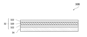
- FIG. 1 is a schematic cross-sectional view of a positive electrode according to an embodiment of the present invention
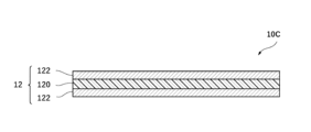
- 1 is a schematic cross-sectional view of a negative electrode according to an embodiment of the present invention
- FIG. 2 is a schematic cross-sectional view of another example of a lithium secondary battery according to an embodiment of the present invention.
- FIG. 2 is a schematic cross-sectional view of another example of a negative electrode according to an embodiment of the present invention.
- the present embodiment an embodiment of the present invention (hereinafter referred to as "the present embodiment") will be described in detail with reference to the drawings as necessary, but the present invention is not limited to this, and various modifications are possible without departing from the gist of the invention.
- the same elements are given the same reference numerals, and duplicated explanations will be omitted.
- positional relationships such as up, down, left, and right will be based on the positional relationships shown in the drawings.
- the dimensional ratios of the drawings are not limited to those shown in the drawings.
- Lithium Secondary Battery The type of the lithium secondary battery of the present embodiment is not particularly limited as long as it is charged and discharged by an oxidation-reduction reaction of lithium, and examples of the battery include an anode-free type lithium secondary battery, a lithium ion battery, a lithium metal battery, a lithium sulfur battery, a lithium oxygen battery, and a lithium air battery.
- the shape of the battery of the lithium secondary battery of this embodiment is not particularly limited, and may be, for example, a sheet type, a laminated sheet type, a thin shape, a cylindrical shape with a bottom, a rectangular shape with a bottom, etc. From the viewpoint of more effectively and reliably achieving the effects of this embodiment, a sheet type, a laminated sheet type, or a thin shape is preferable.
- anode-free lithium secondary battery hereinafter also simply referred to as an “anode-free battery” or “AFB"
- AFB anode-free battery
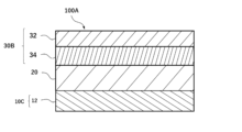
- FIG. 1 is a diagram showing an example of a cross-sectional structure of an anode-free type lithium secondary battery according to one embodiment of the present invention.
- the anode-free type lithium secondary battery 100A includes a positive electrode 30B having a positive electrode current collector 32 and a positive electrode active material layer 34, a negative electrode 10C having a negative electrode current collector 12, an electrolyte, and a separator 20, in which the positive electrode current collector 32 and/or the negative electrode current collector 12 has a current collector film including a resin layer containing polyethylene terephthalate and metal layers provided on both sides of the resin layer, and the positive electrode active material layer 34 is a current collector film having a metal layer represented by the general formula: Li z Ni x Co y M 1-x-y O 2 + ⁇ (wherein 0.5 ⁇ x ⁇ 1.0, 0 ⁇ y ⁇ 0.35, 0.9 ⁇ z ⁇ 1.3, -0.2 ⁇ 0.15, and M is one or more elements selected from the group consisting of Mn, Al, V, Mg, Mo, Nb, Ti, Zr, Fe, Cu, Cr, Zn, F, and B), and the electrolyte contains a
- the positive electrode active material layer 34 may be formed on at least one surface of the positive electrode collector 32 to form the positive electrode 30B, or, although not shown, the positive electrode active material layer 34 may be formed on both surfaces of the positive electrode collector 32 to form the positive electrode 30.
- the positive electrode of this embodiment, including the positive electrode 30B, is referred to as the positive electrode 30.
- the negative electrode of this embodiment which does not have a negative electrode active material layer 14 and includes a negative electrode 10C consisting of only a negative electrode current collector 12, is referred to as a negative electrode 10.
- the positive electrode collector 32 includes a resin layer 320 and a metal layer 322 provided on both sides of the resin layer 320, but the positive electrode collector 32 may include the metal layer 322 without the resin layer 320.
- the negative electrode collector 12 includes a resin layer 120 and a metal layer 122 provided on both sides of the resin layer 120, but the negative electrode collector 12 may include the metal layer 122 without the resin layer 120.
- at least one of the positive electrode collector 32 and the negative electrode collector 12 includes a collector film (hereinafter simply referred to as a "collector film”) including a resin layer and a metal layer provided on both sides of the resin layer.
- the resin layer may melt in the event of abnormal heat generation due to overcharging or high temperature conditions, and may function to cut off the short circuit current inside the battery. This tends to suppress a sudden increase in temperature inside the battery, suppress battery ignition, and contribute to high safety.
- the positive electrode collector and/or the negative electrode collector have a collector film
- the specific gravity is smaller than when they have only a metal layer, so the energy density per unit weight tends to be improved.
- lithium secondary batteries current collector films are often used, taking into consideration the above-mentioned advantages.
- Polyethylene terephthalate (PET) which has excellent mechanical properties and workability, is often used as the material for the resin layer.
- Chain carbonates and/or chain ethers are often used as the electrolyte to improve the performance (energy density, cycle characteristics, capacity retention rate, etc.) of lithium secondary batteries.
- the inventors After extensive research, the inventors have found that by including vinylene carbonate and lithium difluorophosphate, the electrolyte components chain carbonate and/or chain ether can be prevented from chemically reacting with PET, even when a charged lithium secondary battery is stored at high temperatures, and the high performance of the lithium secondary battery can be maintained.
- the reasons for this are presumed to be as follows, but are not limited to these.
- the positive electrode active material is a compound represented by the general formula: Li z Ni x Co y M 1-x-y O 2 + ⁇ (wherein 0.5 ⁇ x ⁇ 1.0, 0 ⁇ y ⁇ 0.35, 0.9 ⁇ z ⁇ 1.3, ⁇ 0.2 ⁇ 0.15, M is one or more elements selected from the group consisting of Mn, Al, V, Mg, Mo, Nb, Ti, Zr, Fe, Cu, Cr, Zn, F, and B), it is speculated that the above-mentioned redox shuttle reaction becomes more prominent.
- the above-mentioned redox shuttle reaction changes the composition of the electrolyte components and reduces the mass of the electrolyte components, which is presumably degrading the performance of the lithium secondary battery, such as the remaining capacity rate.
- the above-mentioned redox shuttle reaction is presumed to occur not only in dimethyl carbonate, but also in chain carbonates such as ethyl methyl carbonate and ethylene carbonate, and chain ethers such as dimethoxyethane, diethoxyethane, dimethoxypropane, dimethoxybutane, and diethylene glycol dimethyl ether.
- the lithium secondary battery of this embodiment can achieve both high safety and excellent performance stability at high temperatures.
- the factors behind this are not limited to those mentioned above.
- the positive electrode 30 of the present embodiment includes a positive electrode current collector 32 and a positive electrode active material layer 34.
- the average thickness of the positive electrode 30 of the anode-free battery is not particularly limited, but is, for example, 20 ⁇ m to 100 ⁇ m, 30 ⁇ m to 80 ⁇ m, or 40 ⁇ m to 70 ⁇ m. However, the average thickness of the positive electrode 30 can be adjusted appropriately depending on the desired battery capacity.
- the positive electrode current collector 32 of the present embodiment may have a current collector film including a resin layer 320 containing polyethylene terephthalate and a metal layer 322 provided on both sides of the resin layer 320, or may have the metal layer 322 without the resin layer 320.
- the metal layer 322 is formed by attaching the metal layer 322 to the surfaces on both sides of the resin layer 320 by vapor deposition, sputtering, electrolytic plating, or with an adhesive.
- the resin layer 320 of the positive electrode current collector 32 of this embodiment is an insulator and prevents the metal layers 322 provided on both sides of the resin layer 320 from being electrically connected to each other.
- the resin constituting the resin layer 320 is not particularly limited, and may be, for example, a sheet-shaped (film-shaped) or fibrous resin.
- the resin may include polyethylene terephthalate (PET) and may further include other resins.
- PET polyethylene terephthalate
- the other resins include polyolefin resins such as polyethylene and polypropylene, and thermoplastic resins such as polystyrene, polyvinyl chloride, or polyamide.
- the other resins may be used alone or in combination of two or more.
- the resin layer 320 may contain other additives as appropriate depending on the desired physical properties.
- additives include, but are not limited to, colorants, flame retardants, surfactants, etc.
- the resin content is not particularly limited, but may be, for example, 60% by mass or more and 100% by mass or less, 80% by mass or more and 100% by mass or less, 90% by mass or more and 100% by mass or less, 95% by mass or more and 100% by mass or less, or 100% by mass, relative to the total amount of the resin layer 320.
- the amount of PET contained is not particularly limited, but may be, for example, 60% by mass or more and 100% by mass or less, 80% by mass or more and 100% by mass or less, 90% by mass or more and 100% by mass or less, 95% by mass or more and 100% by mass or less, or 100% by mass, relative to the total amount of the resin layer 320.
- the amount of PET is not particularly limited, but may be, for example, 80% by mass or more and 100% by mass or less, 85% by mass or more and 100% by mass or less, 90% by mass or more and 100% by mass or less, 95% by mass or more and 100% by mass or less, 98% by mass or more and 100% by mass or less, or 100% by mass, relative to the total amount of resin.
- the thickness of the resin layer 320 is not particularly limited, but is, for example, 2 ⁇ m or more and 15 ⁇ m or less, 3 ⁇ m or more and 12 ⁇ m or less, or 4 ⁇ m or more and 10 ⁇ m or less.
- the metal layer 322 of the positive electrode current collector 32 of this embodiment is in physical and/or electrical contact with the positive electrode active material layer 34 and functions to give and receive electrons to and from the positive electrode active material layer 34.
- the metal layer 322 is made of a conductor such as a metal that does not react with lithium in a battery.
- the metal constituting the metal layer 322 is not particularly limited, but is at least one selected from the group consisting of aluminum, titanium, stainless steel, nickel, and alloys thereof. Among these, aluminum or an aluminum alloy is preferable, and aluminum is particularly preferable.
- the metal may be used alone or in combination of two or more.
- the term "metal that does not react with lithium” means a metal that does not react with lithium ions or lithium metal to form an alloy under the operating conditions of a lithium secondary battery.
- the thickness of the metal layer 322 is not particularly limited, but is, for example, 0.1 ⁇ m to 4.0 ⁇ m, 0.2 ⁇ m to 3.0 ⁇ m, 0.3 ⁇ m to 2.5 ⁇ m, or 0.4 ⁇ m to 2.0 ⁇ m.
- the thickness of the metal layer 322 is not particularly limited, but is, for example, 4.0 ⁇ m or more and 20.0 ⁇ m or less, 6.0 ⁇ m or more and 17.5 ⁇ m or less, or 8.0 ⁇ m or more and 15.0 ⁇ m or less.
- the positive electrode active material of the present embodiment is not particularly limited, but is, for example, contained in a positive electrode active material composition including a binder, a conductive assistant, a sacrificial positive electrode agent, and other additives.
- the positive electrode active material composition is applied to at least one surface or both surfaces of the positive electrode current collector 32, and press-molded to form a positive electrode active material layer 34 on at least one surface or both surfaces of the positive electrode current collector 32.
- the method of disposing the positive electrode active material layer 34 on the positive electrode current collector 32 is not limited to press molding, and examples of the method include a method in which a thermosetting compound is added to the positive electrode active material composition and then heated to harden it, a method in which a photocurable compound is added to the positive electrode active material composition and then irradiated with light to harden it, and a method in which the positive electrode active material composition is a two-component hardening composition and then hardened by mixing the two components, etc.
- the positive electrode active material layer 34 of this embodiment contains one or more compounds represented by the general formula: LizNixCoyM1 -x- yO2 + ⁇ (wherein 0.5 ⁇ x ⁇ 1.0, 0 ⁇ y ⁇ 0.35, 0.9 ⁇ z ⁇ 1.3, ⁇ 0.2 ⁇ 0.15, and M is one or more elements selected from the group consisting of Mn, Al, V, Mg, Mo, Nb, Ti, Zr, Fe, Cu, Cr, Zn, F, and B).
- the positive electrode active material layer 34 contains one or more compounds represented by the general formula: Li z Ni x Co y M 1-x-y O 2 + ⁇ (wherein 0.7 ⁇ x ⁇ 1.0, 0 ⁇ y ⁇ 0.35, 0.9 ⁇ z ⁇ 1.3, ⁇ 0.2 ⁇ 0.15, M is one or more elements selected from the group consisting of Mn, Al, V, Mg, Mo, Nb, Ti, Zr, Fe, Cu, Cr, Zn, F, and B.).
- M is one or more elements selected from the group consisting of Mn, Al, V, Mg, Mo, Nb, Ti, Zr, Fe, Cu, Cr, Zn, F, and B.
- the above-mentioned redox shuttle reaction is more likely to occur, but by containing an additive to be described in detail below in the electrolyte, the reaction is suppressed, and there is a tendency for the electrolyte to have excellent performance stability at high temperatures.
- the positive electrode active material may include other positive electrode active materials other than the above-mentioned compounds.
- the positive electrode active material is a material that causes an electrode reaction, i.e., an oxidation reaction and a reduction reaction, at the positive electrode.
- the other positive electrode active material of this embodiment may include a host material of a lithium element (typically, a lithium ion).
- Such other positive electrode active materials include, but are not limited to, metal oxides and metal phosphates.
- the metal oxides include, but are not limited to, cobalt oxide-based compounds, manganese oxide-based compounds, and nickel oxide-based compounds.
- the metal phosphates include, but are not limited to, iron phosphate-based compounds, and cobalt phosphate-based compounds.
- the other positive electrode active materials may be used alone or in combination of two or more.
- the amount of the positive electrode active material relative to the total amount of the positive electrode active material composition is not particularly limited, but may be, for example, 60% by mass or more and 100% by mass or less, 70% by mass or more and 99% by mass or less, 80% by mass or more and 98% by mass or less, 85% by mass or more and 97% by mass or less, or 90% by mass or more and 96% by mass or less.
- the positive electrode active material composition of the present embodiment may contain a binder.
- a binder By containing a binder, the positive electrode active material layer 34 is more easily bound to the positive electrode current collector 32, and flexibility is improved after the positive electrode active material layer 34 is disposed on the positive electrode current collector 32.
- the binder of this embodiment is not particularly limited, but examples thereof include polyvinylidene fluoride; modified polyvinylidene fluoride obtained by introducing functional groups such as hydroxyl groups, amino groups, carbonyl groups, carboxyl groups, phenyl groups, and methyl groups into polyvinylidene fluoride; polytetrafluoroethylene; modified polytetrafluoroethylene obtained by introducing functional groups such as hydroxyl groups, amino groups, carbonyl groups, carboxyl groups, phenyl groups, and methyl groups into polytetrafluoroethylene; block copolymers, random copolymers, and graft copolymers having tetrafluoroethylene as a constituent unit; styrene butadiene rubber; carboxymethyl cellulose; acrylic resins; polyimide resins, and the like.
- the binder may be used alone or in combination of two or more types.
- the amount of binder contained is not particularly limited relative to the total amount of the positive electrode active material composition, but is, for example, 0.5% by mass to 10.0% by mass, 1.0% by mass to 8.0% by mass, or 2.0% by mass to 6.0% by mass.
- the positive electrode active material composition of the present embodiment may contain a conductive assistant.
- the conductive assistant is not particularly limited, but may be, for example, carbon black, single-walled carbon nanotube (SWCNT), multi-walled carbon nanotube (MWCNT), carbon nanofiber (CF), and acetylene black.
- the conductive assistant may be used alone or in combination of two or more kinds.
- the amount of the conductive additive contained is not particularly limited, but is, for example, 0.5% by mass or more and less than 30.0% by mass relative to the total amount of the positive electrode active material composition.
- the positive electrode active material composition of this embodiment may contain a sacrificial cathode agent.
- the sacrificial cathode agent of this embodiment is a lithium-containing compound that undergoes an oxidation reaction in the charge/discharge potential range of the positive electrode active material and does not substantially undergo a reduction reaction.
- the positive electrode contains a sacrificial cathode agent
- when a lithium secondary battery including the positive electrode is initially charged the positive electrode active material and the sacrificial cathode agent release lithium ions and undergo an oxidation reaction, and release electrons to the negative electrode through an external circuit.
- lithium ions derived from the positive electrode active material and the sacrificial cathode agent are deposited on the surface of the negative electrode.
- the lithium metal deposited on the surface of the negative electrode is electrolytically dissolved, and electrons move from the negative electrode to the positive electrode through an external circuit.
- the positive electrode active material receives lithium ions and undergoes a reduction reaction, while the sacrificial cathode agent does not substantially undergo a reduction reaction within the range of the discharge potential of the positive electrode active material, and it is substantially impossible to return to the state before the oxidation reaction occurred.
- the lithium secondary battery when the lithium secondary battery is discharged after the initial charge, the lithium metal derived from the positive electrode active material is electrolytically dissolved from the negative electrode, whereas most of the lithium metal derived from the sacrificial positive electrode agent remains on the negative electrode, and even after the discharge of the battery is completed, some of the lithium metal remains on the negative electrode.
- the remaining lithium metal serves as a scaffold for further lithium metal to deposit on the negative electrode in the charging step following the initial discharge, so that the lithium metal is more likely to deposit uniformly on the negative electrode in the charging step following the initial discharge. As a result, the lithium secondary battery tends to have better cycle characteristics.
- the sacrificial positive electrode agent examples include, but are not limited to, lithium oxides such as Li 2 O 2 ; lithium nitrides such as Li 3 N; lithium sulfide solid solutions such as Li 2 S-P 2 S 5 , Li 2 S-LiCl, Li 2 S-LiBr, and Li 2 S-LiI; iron-based lithium oxides such as Li 1+x (Ti 1-y Fe y ) 1-x O 2 (0 ⁇ x ⁇ 0.25, 0.4 ⁇ y ⁇ 0.9), Li 2-x Ti 1-z Fe z O 3-y (0 ⁇ x ⁇ 2, 0 ⁇ y ⁇ 1, 0.05 ⁇ z ⁇ 0.95), and Li 5 FeO 4.
- the sacrificial positive electrode agent may be used alone or in combination of two or more types.
- the amount of the sacrificial positive electrode agent relative to the total amount of the positive electrode active material composition is not particularly limited, but may be, for example, 1.0% by mass or more and 30.0% by mass or less, 2.0% by mass or more and 20.0% by mass or less, or 3.0% by mass or more and 15.0% by mass or less.
- the total amount of the positive electrode active material and the sacrificial positive electrode agent is not particularly limited relative to the total amount of the positive electrode active material composition, but may be, for example, 60% by mass or more and 100% by mass or less, 70% by mass or more and 99% by mass or less, 80% by mass or more and 98% by mass or less, 85% by mass or more and 97% by mass or less, or 90% by mass or more and 96% by mass or less.
- the positive electrode 30 of the present embodiment is produced, for example, as follows, but is not particularly limited.
- a metal layer 322 is formed on both surfaces of the resin layer 320 by deposition, sputtering, electrolytic plating, or bonding with an adhesive to form a current collector film, thereby obtaining the positive electrode current collector 32 of the present embodiment.
- the above-mentioned positive electrode active material, binder, sacrificial positive electrode agent, and other additives are mixed to obtain a positive electrode active material composition.
- the positive electrode active material or the obtained positive electrode active material composition is applied to both sides or one side of the positive electrode current collector 32, and press-molded to form a positive electrode active material layer 34 on both sides or one side of the positive electrode current collector 32, thereby obtaining a molded body.
- the obtained molded body is punched out to a predetermined size by punching processing, thereby obtaining the positive electrode 30 of the present embodiment.
- the negative electrode 10 of this embodiment has a negative electrode current collector 12.
- the negative electrode current collector 12 of the present embodiment may have a current collector film including a resin layer 120 containing polyethylene terephthalate and a metal layer 122 provided on both sides of the resin layer 120, or may have the metal layer 122 without the resin layer 120.
- the metal layer 122 is formed by attaching the metal layer 122 to the surfaces on both sides of the resin layer 120 by vapor deposition, sputtering, electrolytic plating, or with an adhesive.
- the resin layer 120 of the negative electrode current collector 12 of this embodiment is an insulator, and prevents the metal layers 122 provided on both sides of the resin layer 120 from being electrically connected to each other.
- the resin constituting the resin layer 120 is not particularly limited, and may be, for example, a sheet-shaped (film-shaped) or fibrous resin.
- the resin may include polyethylene terephthalate (PET) and may further include other resins. Examples of the other resins include those similar to those in the resin layer 320 of the positive electrode current collector 32.
- the resin layer 120 may also include other additives as appropriate depending on the desired physical properties, and examples of the other additives include those similar to those in the resin layer 320 of the positive electrode current collector 32.
- the resin content and PET content may be the same as the resin content and PET content in the positive electrode current collector 32.
- the thickness of the resin layer 120 may be the same as the thickness of the resin layer 320 in the positive electrode collector 32.
- the metal constituting the metal layer 122 of the negative electrode current collector 12 of this embodiment is not particularly limited as long as it can be used as a current collector, and examples thereof include at least one selected from the group consisting of copper, nickel, titanium, iron, other metals that do not react with lithium, alloys thereof, and stainless steel (SUS), and preferably at least one selected from the group consisting of copper, nickel, alloys thereof, and SUS.
- the thickness of the metal layer 122 may be similar to the thickness of the metal layer 322 in the positive electrode current collector 32 having a current collector film.
- the thickness of the metal layer 122 may be similar to the thickness of the metal layer 322 in the positive electrode current collector 32 which does not have a resin layer 320 but has a metal layer 322.
- the negative electrode active material is a material that causes an electrode reaction, i.e., an oxidation reaction and a reduction reaction, at the negative electrode.
- the negative electrode active material of this embodiment includes a host material of lithium metal and lithium element (lithium ion or lithium metal).
- the host material of lithium element means a material provided to hold lithium ion or lithium metal at the negative electrode. Examples of such a holding mechanism include intercalation, alloying, and metal cluster occlusion, and typically, intercalation.
- the negative electrode active material is not particularly limited, but examples thereof include lithium metal and alloys containing lithium metal, carbon-based materials, metal oxides, metals that alloy with lithium and alloys containing said metals, etc.
- the carbon-based materials are not particularly limited, but examples thereof include graphene, graphite, hard carbon, carbon nanotubes, etc.
- the metal oxides are not particularly limited, but examples thereof include titanium oxide-based compounds and cobalt oxide-based compounds, etc.
- the metals that alloy with lithium are not particularly limited, but examples thereof include silicon, germanium, tin, lead, aluminum, and gallium.
- the anode-free lithium secondary battery of this embodiment has a negative electrode 10 made of a negative electrode current collector 12 that does not have a negative electrode active material, and uses the electrolyte solution described below.
- an anode-free battery before the initial charge of the battery, the negative electrode 10 does not have any negative electrode active material and consists only of the negative electrode current collector 12. Therefore, after the initial charge, lithium metal is deposited on the negative electrode 10, and charging and discharging are performed by electrolytic dissolution of the deposited lithium metal. Therefore, an anode-free battery has the advantage that the volume occupied by the negative electrode active material and the mass of the negative electrode active material are reduced, and the volume and mass of the entire battery are reduced, so that the energy density is, in principle, high.
- the negative electrode “has no negative electrode active material” means that the negative electrode does not have or substantially does not have a negative electrode active material.
- the negative electrode substantially does not have a negative electrode active material means that the content of the negative electrode active material in the negative electrode is 10.0 mass% or less with respect to the entire negative electrode.
- the content of the negative electrode active material in the negative electrode 10 of the anode-free battery is preferably 5.0 mass% or less, 1.0 mass% or less, 0.1 mass% or less, or 0.0 mass% with respect to the entire negative electrode 10.
- the battery when the battery is "before the initial charge” it means the state from when the battery is assembled until the first charge. Also, when the battery is “at the end of discharge” it means the state in which the battery voltage is preferably 1.0 V or more and 3.8 V or less, and more preferably 1.0 V or more and 3.0 V or less.
- the lithium metal content when the battery voltage is 1.0 V or more and 3.5 V or less, the lithium metal content may be 10.0 mass % or less (preferably 5.0 mass % or less, 1.0 mass % or less) relative to the entire negative electrode 10; when the battery voltage is 1.0 V or more and 3.0 V or less, the lithium metal content may be 10.0 mass % or less (preferably 5.0 mass % or less, 1.0 mass % or less) relative to the entire negative electrode 10; or when the battery voltage is 1.0 V or more and 2.5 V or less, the lithium metal content may be 10.0 mass % or less (preferably 5.0 mass % or less, 1.0 mass % or less) relative to the entire negative electrode 10.
- the ratio M3.0/ M4.2 of the mass M3.0 of lithium metal deposited on the negative electrode 10 when the battery voltage is 3.0 V to the mass M4.2 of lithium metal deposited on the negative electrode 10 when the battery voltage is 4.2 V is preferably 40.0 % or less, 38.0% or less, or 35.0% or less.
- the ratio M3.0 / M4.2 may be 1.0% or more, 2.0% or more, 3.0% or more , or 4.0% or more.
- the average thickness of the negative electrode 10 of the anode-free battery is not particularly limited, but is, for example, 3.0 ⁇ m or more and 30.0 ⁇ m or less. From the viewpoint of reducing the volume occupied by the negative electrode 10 in the anode-free battery and improving the energy density, the average thickness of the negative electrode 10 is preferably 4.0 ⁇ m or more and 20.0 ⁇ m or less, 5.0 ⁇ m or more and 18.0 ⁇ m or less, or 6.0 ⁇ m or more and 15 ⁇ m or less.
- the negative electrode 10 of the present embodiment is manufactured, for example, as follows, without any particular limitation.
- a metal layer 122 is formed on both surfaces of the resin layer 120 by vapor deposition, sputtering, electrolytic plating, or bonding with an adhesive to form a current collector film, thereby obtaining the negative electrode current collector 12 of the present embodiment. Since an anode-free type lithium secondary battery does not have a negative electrode active material, the above-mentioned negative electrode current collector 12 can be used as the negative electrode 10 of the present embodiment.
- the separator 20 of the present embodiment is not particularly limited as long as it has the function of physically and/or electrically isolating the positive electrode 30 and the negative electrode 10 and the function of ensuring the ion conductivity of lithium ions.
- Examples of such a separator include insulating porous members, polymer electrolytes, gel electrolytes, and inorganic solid electrolytes, and typically includes at least one selected from the group consisting of insulating porous members, polymer electrolytes, and gel electrolytes.
- one type of member may be used alone, or two or more types of members may be used in combination.
- an insulating porous material preferably, a polymer electrolyte, or a gel electrolyte is used alone or in combination of two or more. If an insulating porous material is used alone as the separator 20, the lithium secondary battery must further include an electrolyte.
- the polymer electrolyte is not particularly limited, but examples thereof include solid polymer electrolytes mainly containing a polymer and an electrolyte, and semi-solid polymer electrolytes mainly containing a polymer, an electrolyte, and a plasticizer.
- the gel electrolyte is not particularly limited, but may be, for example, one that mainly contains a polymer and a liquid electrolyte (i.e., a solvent and an electrolyte).
- Polymers that may be included in the polymer electrolyte and gel electrolyte include, but are not limited to, polymers containing functional groups containing oxygen atoms such as ethers and esters, halogen groups, and polar groups such as cyano groups.
- resins having ethylene oxide units in the main chain and/or side chains such as polyethylene oxide (PEO), resins having propylene oxide units in the main chain and/or side chains such as polypropylene oxide (PPO), acrylic resins, vinyl resins, ester resins, nylon resins, polyvinylidene fluoride (PVdF), polyacrylonitrile (PAN), polysiloxane, polyphosphazene, polymethylmethacrylate, polyamide, polyimide, aramid, polylactic acid, polyurethane, polyacetal, polysulfone, polyethylene carbonate, polypropylene carbonate, and polytetrafluoroethylene.
- the above resins may be used alone or in combination of two or more.
- the electrolyte contained in the polymer electrolyte and the gel electrolyte includes salts of Li, Na, K, Ca, and Mg, etc.
- the polymer electrolyte and the gel electrolyte include a lithium salt.
- the lithium salt is not particularly limited, but examples thereof include LiI, LiCl, LiBr , LiF, LiBF4 , LiPF6, LiAsF6 , LiSO3CF3 , LiN ( SO2F ) 2 , LiN ( SO2CF3 ) 2 , LiN( SO2CF3CF3)2, LiB(O2C2H4)2, LiB(C2O4)2 , LiB ( O2C2H4 ) F2 , LiB ( OCOCF3 ) 4 , LiNO3 , and Li2SO4 , and preferably LiPF6 , LiN( SO2F ) 2 , LiN( SO2
- the salt is at least one selected from the group consisting of LiN(SO 2 CF 3 CF 3 ) 2 , and LiN(SO 2 CF 3 CF 3 ) 2.
- the above-mentioned salts or lithium salts may be used alone or in combination of two or more.
- the compounding ratio of the polymer and the lithium salt in the polymer electrolyte and the gel electrolyte may be determined by the ratio of the polar group of the polymer to the lithium atoms of the lithium salt.
- the compounding ratio of the polymer and the lithium salt can be adjusted so that the ratio ([Li]/[O]) is, for example, 0.02 or more and 0.20 or less, 0.03 or more and 0.15 or less, or 0.04 or more and 0.12 or less.
- the solvent contained in the gel electrolyte is not particularly limited, but for example, the solvents that can be contained in the electrolyte solution described later can be used alone or in combination of two or more. Examples of preferred solvents are the same as those in the electrolyte solution described later.
- the plasticizer contained in the semi-solid polymer electrolyte is not particularly limited, but may include, for example, components similar to the solvent that may be contained in the gel electrolyte, and various oligomers.
- the separator 20 includes an insulating porous material
- the pores of the material are filled with a substance having ion conductivity, and the material exhibits ion conductivity. Therefore, in this embodiment, the material is filled with, for example, the electrolyte solution of this embodiment, or a gel electrolyte containing the electrolyte solution of this embodiment.
- the material constituting the insulating porous member is not particularly limited, and examples thereof include insulating polymeric materials, specifically, polyethylene (PE) and polypropylene (PP).
- the separator 20 may be a porous polyethylene (PE) film, a porous polypropylene (PP) film, or a laminated structure thereof.
- the separator 20 may be coated with a separator coating layer.
- the separator coating layer may cover both sides of the separator 20, or only one side. From the viewpoint of improving the cycle characteristics of the lithium secondary battery in this embodiment, it is preferable to coat both sides of the separator 20.
- the separator coating layer in this embodiment is a uniformly continuous film-like coating layer, for example, a film-like coating layer that is uniformly continuous over an area of 50% or more of the separator 20 surface.
- the separator coating layer is not particularly limited, but is preferably one that contains a binder such as polyvinylidene fluoride (PVdF), a mixture of styrene butadiene rubber and carboxymethyl cellulose (SBR-CMC), and polyacrylic acid (PAA).
- the separator coating layer may contain inorganic particles such as silica, alumina, titania, zirconia, and magnesium hydroxide added to the above binder.
- the average thickness of the separator 20 including the separator coating layer is not particularly limited, but is, for example, 3.0 ⁇ m or more and 40.0 ⁇ m or less.
- the average thickness of the separator 20 is preferably 5.0 ⁇ m or more and 30.0 ⁇ m or less, 7.0 ⁇ m or more and 10.0 ⁇ m or less, or 10.0 ⁇ m or more and 20.0 ⁇ m or less.
- Electrolyte The electrolyte of the present embodiment contains a chain carbonate and/or a chain ether, vinylene carbonate, and lithium difluorophosphate.
- the electrolyte may be impregnated into the separator 20, or may be enclosed together with the laminate of the negative electrode 10, the separator 20, and the positive electrode 30.
- the electrolyte of the present embodiment may be one or more of the electrolytes that may be contained in the polymer electrolyte and the gel electrolyte, particularly the lithium salts described above.
- a preferred lithium salt is at least one selected from the group consisting of hexafluorophosphate (LiPF 6 ) and lithium bis(fluorosulfonyl)imide (LiN(SO 2 F) 2 ). Lithium secondary batteries using electrolytic solutions containing these electrolytes tend to have excellent battery performance, such as cycle characteristics.
- the concentration of the electrolyte in the electrolyte solution of this embodiment is not particularly limited, but may be, for example, 0.1 M or more and 6.0 M or less, 0.2 M or more and 5.0 M or less, 0.3 M or more and 4.0 M or less, 0.4 M or more and 3.0 M or less, or 0.5 M or more and 2.0 M or less.
- the solvent of the electrolyte solution of this embodiment includes a chain carbonate and/or a chain ether.
- the chain carbonate is a carbonate that does not have a cyclic structure such as an aromatic ring, an alicyclic ring, a monocyclic ring, or a heterocyclic ring.
- the chain carbonate is not particularly limited, but examples thereof include dimethyl carbonate, diethyl carbonate, ethyl methyl carbonate, ethylene carbonate, propylene carbonate, chloroethylene carbonate, and compounds in which some or all of the hydrogen atoms of these carbonates are replaced with fluorine. Among these, dimethyl carbonate and ethyl methyl carbonate are preferred.
- the chain ether is an ether that does not have a cyclic structure such as an aromatic ring, an alicyclic ring, a monocyclic ring, or a heterocyclic ring.
- the chain ether is not particularly limited, but examples thereof include 1,1,2,2-tetrafluoroethyl-2,2,3,3-tetrafluoropropyl ether, 1,1,2,2-tetrafluoroethyl-2,2,2-trifluoroethyl ether, 1H,1H,5H-octafluoropentyl-1,1,2,2-tetrafluoroethyl ether, triethylene glycol dimethyl ether, tetraethylene glycol dimethyl ether, dimethoxyethane, diethoxyethane, dimethoxypropane, dimethoxybutane, and diethylene glycol dimethyl ether.
- the solvent of the electrolyte solution of this embodiment may contain other solvents in addition to the chain carbonates and chain ethers described above.
- the other solvents are not particularly limited, but examples include non-aqueous solvents having fluorine atoms (hereinafter referred to as "fluorinated solvents") and non-aqueous solvents not having fluorine atoms (hereinafter referred to as “non-fluorinated solvents").
- fluorinated solvents include, but are not limited to, derivatives of 1,1,2,2-tetrafluoroethyl-2,2,3,3-tetrafluoropropyl ether, derivatives of 1,1,2,2-tetrafluoroethyl-2,2,2-trifluoroethyl ether, and derivatives of 1H,1H,5H-octafluoropentyl-1,1,2,2-tetrafluoroethyl ether.
- non-fluorine-containing solvents include, but are not limited to, acetonitrile, methyl acetate, ethyl acetate, propyl acetate, methyl propionate, ethyl propionate, trimethyl phosphate, triethyl phosphate, and 12-crown-4.
- the content of the chain carbonate is preferably 40% by volume or more and 100% by volume or less, 50% by volume or more and 100% by volume or less, 60% by volume or more and 100% by volume or less, or 70% by volume or more and 100% by volume or less, relative to the total amount of the electrolyte. It is also preferably 100% by volume.
- the content of the chain ether is preferably 40% by volume or more and 100% by volume or less, 50% by volume or more and 100% by volume or less, 60% by volume or more and 100% by volume or less, or 70% by volume or more and 100% by volume or less, relative to the total volume of the electrolyte. It is also preferably 100% by volume.
- the total amount of the chain carbonate and the chain ether is preferably 40% by volume or more and 100% by volume or less, 50% by volume or more and 100% by volume or less, 60% by volume or more and 100% by volume or less, or 70% by volume or more and 100% by volume or less, relative to the total amount of the electrolyte. It is also preferably 100% by volume.
- the fluorinated solvent and/or non-fluorinated solvent as the other solvents may be used alone or in any combination of two or more in any ratio.
- the content of the fluorinated solvent and non-fluorinated solvent is not particularly limited, and the ratio of the fluorinated solvent to the total solvent may be 0% by volume or more and 60% by volume or less, and the ratio of the non-fluorinated solvent to the total solvent may be 0% by volume or more and 60% by volume or less.
- the electrolyte solution of the present embodiment contains vinylene carbonate and lithium difluorophosphate.
- the content of vinylene carbonate is preferably 0.1% by mass or more and 5.0% by mass or less, 0.2% by mass or more and 4.5% by mass or less, 0.3% by mass or more and 4.0% by mass or less, 0.4% by mass or more and 3.5% by mass or less, 0.5% by mass or more and 3.0% by mass or less, and 0.6% by mass or more and 2.5% by mass or less, relative to the total amount of the solvent.
- the content of lithium difluorophosphate is preferably 0.1% by mass or more and 5.0% by mass or less, 0.2% by mass or more and 4.5% by mass or less, 0.3% by mass or more and 4.0% by mass or less, 0.4% by mass or more and 3.5% by mass or less, 0.5% by mass or more and 3.0% by mass or less, or 0.6% by mass or more and 2.5% by mass or less, relative to the total amount of the solvent.
- lithium bis(fluorosulfonyl)imide also suppresses the occurrence of the redox shuttle reaction described above, and tends to maintain the high performance of the lithium secondary battery, such as the remaining capacity rate, when the charged lithium secondary battery is stored at high temperatures.
- the content of lithium bis(fluorosulfonyl)imide is preferably 0.1% by mass or more and 12.0% by mass or less, 0.5% by mass or more and 10.0% by mass or less, or 1.0% by mass or more and 6.0% by mass or less, based on the total amount of the solvent.
- a usage mode of a lithium secondary battery including an anode-free battery, will be described.
- a positive terminal and a negative terminal for connecting the battery to an external circuit are respectively joined to the positive electrode collector 32 and the negative electrode collector 12.
- the lithium secondary battery is charged and discharged by connecting the negative terminal to one end of an external circuit and the positive terminal to the other end of the external circuit.
- the lithium secondary battery is charged by applying a voltage to the positive and negative terminals such that a current flows from the negative terminal (negative electrode) through the external circuit to the positive terminal (positive electrode).
- the lithium secondary battery is discharged by connecting the positive and negative terminals via a desired external circuit.
- anode-free battery it is presumed that a solid electrolyte interface layer (SEI layer) is formed on the surface of the negative electrode 10 (the interface between the negative electrode 10 and the separator 20) by initial charging, but the battery does not have to have an SEI layer.
- Charging an anode-free battery causes lithium metal precipitation at the interface between the negative electrode 10 and the SEI layer, the interface between the negative electrode 10 and the separator 20, and/or the interface between the SEI layer and the separator 20.
- the lithium metal precipitation formed on the negative electrode 10 is electrolytically dissolved by discharging. If an SEI layer is formed in the battery, the lithium metal precipitation formed at at least one of the interface between the negative electrode 10 and the SEI layer and/or the interface between the SEI layer and the separator 20 is electrolytically dissolved.
- the manufacturing method of the anode-free type battery is not particularly limited as long as it is a method capable of manufacturing a lithium secondary battery having the above-mentioned configuration, and examples thereof include the following methods.
- the positive electrode 30 of this embodiment is obtained by the positive electrode manufacturing method described above.
- the negative electrode 10 of this embodiment is obtained by the negative electrode manufacturing method described above. Note that the negative electrode 10 of the anode-free battery does not have a negative electrode active material.
- the positive electrode collector 32 and the negative electrode collector 12 may each have a collector film including a resin layer containing polyethylene terephthalate and a metal layer provided on both sides of the resin layer, or only the positive electrode collector 32 may have the collector film and the negative electrode collector 12 may have the metal layer 122 without the resin layer 120, or only the negative electrode collector 12 may have the collector film and the positive electrode collector 32 may have the metal layer 322 without the resin layer 320.
- the separator 20 having the above-mentioned configuration is prepared.
- the separator 20 may be manufactured by a conventional method, or a commercially available product may be used.
- a functional buffer layer that is fibrous or porous and that reduces the volume expansion and contraction caused by the dissolution and precipitation of lithium metal may be provided between the separator 20 and the negative electrode 10.
- the functional buffer layer preferably has ionic conductivity or electrical conductivity, but does not have to have this property.
- the positive electrode 30, separator 20, and negative electrode 10 obtained as described above are stacked in this order so that the positive electrode 30 and the separator 20 face each other to obtain a laminate.
- the resulting laminate is enclosed in a sealed container together with an electrolyte to obtain an anode-free battery.
- the sealed container is not particularly limited, but examples thereof include a laminate film.
- the positive electrode 30 and the negative electrode 10 may be stacked alternately in multiple layers with a separator 20 sandwiched between them, which tends to improve battery performance such as energy density.
- a lithium ion battery 100B which is an example of the lithium secondary battery of this embodiment, includes, for example, a positive electrode 30 having a positive electrode current collector 32 and a positive electrode active material layer 34, a negative electrode 10 having a negative electrode current collector 12 and a negative electrode active material layer 14, an electrolyte, and a separator 20, as shown in FIG.
- the positive electrode current collector 32 and/or the negative electrode current collector 12 has a collector film including a resin layer containing polyethylene terephthalate and metal layers provided on both sides of the resin layer
- the positive electrode active material layer 34 is a compound represented by the general formula: Li z Ni x Co y M 1-x-y O 2 + ⁇ (wherein 0.5 ⁇ x ⁇ 1.0, 0 ⁇ y ⁇ 0.35, 0.9 ⁇ z ⁇ 1.3, ⁇ 0.2 ⁇ 0.15, and M is one or more elements selected from the group consisting of Mn, Al, V, Mg, Mo, Nb, Ti, Zr, Fe, Cu, Cr, Zn, F, and B), and the electrolyte solution contains a chain carbonate and/or a chain ether, vinylene carbonate, and lithium difluorophosphate.
- a lithium ion battery (hereinafter also referred to as "LIB") has a host material of lithium element (lithium ion or lithium metal) in its negative electrode, and when the battery is charged, this material is filled with lithium element, and the battery is discharged when the host material releases the lithium element.
- LIBs differ from anode-free batteries in that the negative electrode has a host material of lithium element.
- the materials, configurations and preferred aspects of the positive electrode 30, electrolyte, separator 20 and negative electrode 10 are the same as those described above, except for the points described below.
- the negative electrode 10 of the LIB is not particularly limited as long as it has a host material of lithium element (lithium ion or lithium metal) as the negative electrode active material, and the above-mentioned materials, configurations, etc. can be used.
- the negative electrode active material layer 14 may be formed on at least one surface of the negative electrode current collector 12 to form the negative electrode 10B, or, although not shown, the negative electrode active material layer 14 may be formed on both surfaces of the negative electrode current collector 12 to form the negative electrode 10.
- the average thickness of the negative electrode 10 of the LIB is not particularly limited, but is, for example, 5.0 ⁇ m or more and 100.0 ⁇ m or less. From the viewpoint of improving the capacity and/or energy density of the battery, it is preferably 8.0 ⁇ m or more and 50.0 ⁇ m or less, 10.0 ⁇ m or more and 40.0 ⁇ m or less, or 10.0 ⁇ m or more and 20.0 ⁇ m or less.
- the LIB may be produced using known materials and known production methods, and may be produced in the same manner as the above-mentioned anode-free battery production method, except that a lithium host material is used for the negative electrode 10.
- the method for producing the negative electrode 10 having the negative electrode active material is not particularly limited, but is, for example, as follows. If necessary, the above-mentioned negative electrode active material is mixed with a binder, a conductive assistant, and other additives, which will be described in detail below, to obtain a negative electrode active material composition. The negative electrode active material or the obtained negative electrode active material composition is applied to both sides or one side of the above-mentioned negative electrode current collector 12, and press molded to form a negative electrode active material layer 14 on both sides or one side of the negative electrode current collector 12, thereby obtaining a molded body. The obtained molded body is punched out to a predetermined size by a punching process, to obtain the negative electrode 10 of this embodiment.
- the amount of the negative electrode active material relative to the total amount of the negative electrode active material composition is not particularly limited, but may be, for example, 60% by mass or more and 100% by mass or less, 70% by mass or more and 99% by mass or less, or 80% by mass or more and 98% by mass or less.
- the binder of the negative electrode active material composition of this embodiment is not particularly limited, but may be, for example, the same as the binder of the positive electrode active material composition.
- the content of the binder in the negative electrode active material composition is not particularly limited, but may be, for example, approximately the same as the content of the binder in the positive electrode active material composition.
- the conductive assistant in the negative electrode active material composition of this embodiment is not particularly limited, but may be, for example, the same as the conductive assistant in the positive electrode active material composition.
- the content of the conductive assistant in the negative electrode active material composition is not particularly limited, but may be, for example, approximately the same as the content of the conductive assistant in the positive electrode active material composition.
- the method of disposing the negative electrode active material layer 14 on the negative electrode current collector 12 is not limited to press molding, and examples of the method include a method in which the negative electrode active material composition contains a thermosetting compound and is heated to harden it, a method in which the negative electrode active material composition contains a photocurable compound and is hardened by irradiating it with light, and a method in which the negative electrode active material composition is a two-component hardening composition and is hardened by mixing the two components, etc.
- Lithium metal battery A lithium metal battery (hereinafter, also referred to as "LMB"), which is an example of a lithium secondary battery of this embodiment, is manufactured using an electrode having lithium metal or a lithium metal alloy on its surface, or lithium metal alone, as the negative electrode.
- LMB lithium metal battery
- the LMB like an anode-free battery, lithium metal is deposited on the surface of the negative electrode, and the deposited lithium is electrolytically dissolved, thereby charging and discharging the LMB.
- LMBs differ from anode-free batteries in that the negative electrode has lithium metal as the negative electrode active material before the battery is initially charged.
- the lithium metal battery of this embodiment includes a positive electrode 30, a negative electrode 10 having lithium metal facing the positive electrode 30, a separator 20 disposed between the positive electrode 30 and the negative electrode 10, and an electrolyte.
- the materials, configurations, and preferred aspects of the positive electrode 30, electrolyte, separator 20, and negative electrode 10 are the same as those described above, except for the points described below.
- the negative electrode 10 of the LMB is not particularly limited as long as it contains lithium metal or a lithium metal alloy as the negative electrode active material, and the above-mentioned materials and configurations can be used. Since the LMB uses a negative electrode 10 having lithium metal or a lithium metal alloy with a large specific capacity and a low redox potential, it generally becomes a battery with a higher energy density than a lithium ion battery. Examples of such a negative electrode 10 include a lithium metal electrode, an electrode in which rolled lithium metal foil is laminated to the surface of a conductive metal foil such as copper to form a clad material, an electrode in which lithium metal is electrochemically deposited on the surface of a metal foil such as copper, and an electrode in which metallic lithium is vacuum-deposited.
- an electrode in which lithium metal foil is laminated to the surface of a conductive metal such as copper, or an electrode in which lithium metal is electrochemically deposited is preferable, and an electrode in which lithium metal foil is laminated to the surface of a conductive metal such as copper is more preferable.
- the negative electrode active material layer 14 may be formed on at least one surface of the negative electrode current collector 12 to form the negative electrode 10B, or, although not shown, the negative electrode active material layer 14 may be formed on both surfaces of the negative electrode current collector 12 to form the negative electrode 10.
- the average thickness of the negative electrode 10 of the LMB is not particularly limited, but is, for example, 5.0 ⁇ m or more and 100.0 ⁇ m or less. From the viewpoint of improving the capacity and/or energy density of the battery, it is preferably 8.0 ⁇ m or more and 50.0 ⁇ m or less, 10.0 ⁇ m or more and 40.0 ⁇ m or less, or 10.0 ⁇ m or more and 20.0 ⁇ m or less.
- the LMB may be produced using known materials and known production methods, and may be produced in the same manner as the anode-free battery described above, except that lithium metal or a lithium metal alloy is used as the negative electrode active material for the negative electrode 10.
- the method for producing the negative electrode 10 having the negative electrode active material is not particularly limited, but is, for example, as follows. If necessary, the above-mentioned negative electrode active material is mixed with a binder, a conductive assistant, and other additives, which will be described in detail below, to obtain a negative electrode active material composition. The negative electrode active material or the obtained negative electrode active material composition is applied to both sides or one side of the above-mentioned negative electrode current collector 12, and press molded to form a negative electrode active material layer 14 on both sides or one side of the negative electrode current collector 12, thereby obtaining a molded body. The obtained molded body is punched out to a predetermined size by a punching process, to obtain the negative electrode 10 of this embodiment.
- the amount of the negative electrode active material relative to the total amount of the negative electrode active material composition is not particularly limited, but may be, for example, 60% by mass or more and 100% by mass or less, 70% by mass or more and 99% by mass or less, or 80% by mass or more and 98% by mass or less.
- the binder of the negative electrode active material composition of this embodiment is not particularly limited, but may be, for example, the same as the binder of the positive electrode active material composition.
- the content of the binder in the negative electrode active material composition is not particularly limited, but may be, for example, approximately the same as the content of the binder in the positive electrode active material composition.
- the conductive assistant in the negative electrode active material composition of this embodiment is not particularly limited, but may be, for example, the same as the conductive assistant in the positive electrode active material composition.
- the content of the conductive assistant in the negative electrode active material composition is not particularly limited, but may be, for example, approximately the same as the content of the conductive assistant in the positive electrode active material composition.
- the method of disposing the negative electrode active material layer 14 on the negative electrode current collector 12 is not limited to press molding, and examples of the method include a method in which the negative electrode active material composition contains a thermosetting compound and is heated to harden it, a method in which the negative electrode active material composition contains a photocurable compound and is hardened by irradiating it with light, and a method in which the negative electrode active material composition is a two-component hardening composition and is hardened by mixing the two components, etc.
- Lithium ion secondary batteries of the examples and comparative examples were fabricated as follows.
- a current collector film was prepared by depositing 1.0 ⁇ m of Cu as the metal layer 122 on both sides of a 6 ⁇ m-thick film-like polyethylene terephthalate (PET) resin layer 120. Then, a negative electrode active material composition was prepared by mixing 97.0 parts by mass of graphite as the negative electrode active material, 0.5 parts by mass of carbon black as a conductive assistant, and 1.5 parts by mass of carboxymethyl cellulose (CMC) and 1.0 parts by mass of styrene-butadiene rubber (SBR) as binders in water as a solvent.
- CMC carboxymethyl cellulose
- SBR styrene-butadiene rubber
- This negative electrode active material composition was applied to one side of the negative electrode current collector 12 so that the basis weight was 15 mg/cm 2 , and pressed to form a negative electrode active material layer 14 on one side of the negative electrode current collector 12, and a molded body was obtained. This molded body was cut out to a predetermined size (4 ⁇ 4 cm). As a result, a negative electrode 10 was obtained. In Table 1, this negative electrode 10 is referred to as a "current collector film type.”
- a copper foil with a thickness of 8 ⁇ m was prepared as the negative electrode current collector 12, and the above-mentioned negative electrode active material composition was applied to one side of the copper foil in the same manner as above, and pressed to form a negative electrode active material layer 14 on one side of the negative electrode current collector 12, thereby obtaining a molded body.
- This molded body was cut to a specified size (4 x 4 cm). In this way, a negative electrode 10 was obtained.
- this negative electrode 10 is referred to as the "metal type".
- a collector film was used in which 1.0 ⁇ m of Al was vapor-deposited on both sides of a 6.0 ⁇ m-thick film-like PET resin layer 320.
- a positive electrode active material composition was prepared by mixing 96 parts by mass of LiNi 0.8 Co 0.15 Al 0.05 O 2 as a positive electrode active material, 2 parts by mass of carbon black as a conductive assistant, and 2 parts by mass of polyvinylidene fluoride (PVDF) as a binder in N-methyl-pyrrolidone (NMP) as a solvent.
- PVDF polyvinylidene fluoride
- This positive electrode active material composition was applied to one side of the positive electrode collector 32 with a basis weight of 23 mg/cm 2 and pressed to form a positive electrode active material layer 34 on one side of the positive electrode collector 32, and a molded body was obtained. This molded body was cut out to a predetermined size (4 ⁇ 4 cm). As a result, a positive electrode 30 was obtained. In Table 1, this positive electrode 30 is referred to as a "current collector film type.”
- Electrolyte One or more selected from the group consisting of lithium hexafluorophosphate (LiPF 6 ) and lithium bis(fluorosulfonyl)imide (LiFSI) were dissolved in a solvent prepared by mixing one or more selected from the group consisting of ethylene carbonate ( EC ), dimethyl carbonate (DMC), and ethyl methyl carbonate (EMC) in the volume ratios shown in Table 1.
- EC ethylene carbonate
- DMC dimethyl carbonate
- EMC ethyl methyl carbonate
- LiPO 2 F 2 lithium difluorophosphate
- VC vinylene carbonate
- the positive electrode 30, separator 20, and negative electrode 10 obtained as above were stacked in this order so that the positive electrode 30 faced the separator 20 to obtain a laminate. Furthermore, a 100 ⁇ m Al terminal and a 100 ⁇ m Ni terminal were joined to the positive electrode collector 32 and the negative electrode collector 12, respectively, by ultrasonic welding, and then inserted into a laminate exterior body. Next, the electrolyte solution obtained as described above was injected into the exterior body. The exterior body was sealed to obtain lithium ion secondary batteries of the examples and comparative examples.
- the lithium ion secondary batteries of the examples and comparative examples were then CC-charged in a thermostatic chamber at 25°C with a current of 6 mA until the voltage reached 4.2 V, and then CV-charged while maintaining the voltage at 4.2 V until the charging current reached 3 mA. After that, tape was attached to the terminals to prevent short circuits, and the batteries were removed from the thermostatic chamber at 25°C and placed in a thermostatic chamber at 60°C. After being left in the thermostatic chamber at 60°C for two weeks, the lithium ion secondary batteries of the examples and comparative examples were removed from the thermostatic chamber at 60°C and CC-discharged with a current of 6 mA until the voltage reached 2.7 V.
- the discharge capacity thus obtained was taken as the remaining capacity (mAh), and [remaining capacity]/[rated capacity] ⁇ 100 was taken as the capacity remaining rate (%) after high-temperature storage, and is shown in the capacity remaining rate column in Table 1.
- a positive electrode 30 having a positive electrode collector 32 and a positive electrode active material layer 34, a negative electrode 10 having a negative electrode collector 12, an electrolyte, and a separator 20 are included, and the positive electrode collector 32 and/or the negative electrode collector 12 have a collector film including a resin layer containing polyethylene terephthalate and metal layers provided on both sides of the resin layer, and the positive electrode active material layer 34 has a structure represented by the general formula: Li z Ni x Co y M 1-x-y O 2 + ⁇ (wherein 0.5 ⁇ x ⁇ 1.0, 0 ⁇ y ⁇ 0.35, 0.9 ⁇ z ⁇ 1.3, ⁇ 0.2 ⁇ 0.15, and M is one or more elements selected from the group consisting of Mn, Al, V, Mg, Mo, Nb, Ti, Zr, Fe, Cu, Cr, Zn, F, and B), and the electrolyte solution contains a chain carbonate and/or a chain ether, vinylene carbonate, and lithium difluorophosphate, and it is
- the lithium secondary battery of the present invention has excellent capacity retention even when stored at high temperatures, and therefore has industrial applicability as an electricity storage device for a variety of applications.
Landscapes
- Chemical & Material Sciences (AREA)
- General Chemical & Material Sciences (AREA)
- Chemical Kinetics & Catalysis (AREA)
- Electrochemistry (AREA)
- Engineering & Computer Science (AREA)
- Inorganic Chemistry (AREA)
- Manufacturing & Machinery (AREA)
- General Physics & Mathematics (AREA)
- Condensed Matter Physics & Semiconductors (AREA)
- Physics & Mathematics (AREA)
- Materials Engineering (AREA)
- Battery Electrode And Active Subsutance (AREA)
- Secondary Cells (AREA)
- Cell Electrode Carriers And Collectors (AREA)
Abstract
Description
本発明は、リチウム2次電池に関する。 The present invention relates to a lithium secondary battery.
近年、太陽光又は風力等の自然エネルギーを電気エネルギーに変換する技術が注目されている。これに伴い、安全性が高く、かつ多くの電気エネルギーを蓄えることができる蓄電デバイスとして、様々な2次電池が開発されている。 In recent years, technology that converts natural energy such as solar or wind power into electrical energy has been attracting attention. As a result, various secondary batteries have been developed as energy storage devices that are highly safe and can store large amounts of electrical energy.
その中でも、正極及び負極の間をリチウムイオンが移動することで充放電を行うリチウム2次電池は、高電圧及び高エネルギー密度を示すことが知られている。典型的なリチウム2次電池として、正極及び負極にリチウム元素を保持することのできる活物質を有し、当該正極活物質及び負極活物質の間でのリチウムイオンの授受によって充放電をおこなうリチウムイオン2次電池(LIB:Lithium-ion battery)が知られている。 Among these, lithium secondary batteries, which charge and discharge by the movement of lithium ions between the positive and negative electrodes, are known to exhibit high voltage and high energy density. A typical lithium secondary battery is the lithium-ion secondary battery (LIB), which has active materials capable of retaining lithium elements in the positive and negative electrodes and charges and discharges by the exchange of lithium ions between the positive and negative active materials.
例えば、特許文献1には、アノードと、カソードと、アノードおよびカソードの間に設けられた、少なくとも一つのセパレーターと、電解物と、アノードおよびカソードのうち、少なくとも一方に接触する、少なくとも一つの薄膜状の集電体と、少なくとも一つの薄膜状の集電体に取り付けられた、少なくとも一つのタブと、を備え、タブは、接続手段を介して、集電体に取り付けられ、接続手段は、タブの露出面および薄膜状の集電体の間を、電気的に接続し、アノードおよびカソードのうち、いずれか一方は、薄膜状の集電体の少なくとも一部およびセパレーターの間に介在し、集電体は、非導電材料基材を覆う導電材を備え;蓄電装置の動作電圧において、短絡時に、集電体は伝導を停止し、電圧は、少なくとも2.0ボルトである、ことを特徴とする、蓄電装置が開示されている。 For example, Patent Document 1 discloses an electricity storage device comprising an anode, a cathode, at least one separator provided between the anode and the cathode, an electrolyte, at least one thin-film current collector in contact with at least one of the anode and the cathode, and at least one tab attached to the at least one thin-film current collector, the tab being attached to the current collector via a connection means that electrically connects the exposed surface of the tab and the thin-film current collector, one of the anode and the cathode being interposed between at least a portion of the thin-film current collector and the separator, the current collector comprising a conductive material covering a non-conductive material substrate; and at the operating voltage of the electricity storage device, the current collector stops conducting upon short circuit, and the voltage is at least 2.0 volts.
また、特許文献2には、絶縁層を導電層で挟んだ多層構造を有する集電体であって、その端部を2回以上同方向に折り返した折り返し領域を有し、折り返し領域において絶縁層を挟む各導電層が互いに電気的に接続されており、折り返し領域を形成する集電体端部の内面同士が、離間している、または、一部で接触していることを特徴とする、集電体が開示されている。 Patent Document 2 also discloses a current collector having a multi-layer structure in which an insulating layer is sandwiched between conductive layers, the current collector having a folded region in which the end is folded back two or more times in the same direction, the conductive layers sandwiching the insulating layer in the folded region being electrically connected to each other, and the inner surfaces of the current collector ends forming the folded region being separated from each other or partially in contact with each other.
また、特許文献3には、活物質を結着材を介して集電体に付着させてなる正極および負極を備えるリチウムイオン二次電池において、正極および負極のうち少なくとも一方の集電体が、電池の異常発熱時に溶融する樹脂からなる低融点層と、低融点層と活物質との間に介在し活物質と電荷のやり取りを行う金属層と、を備えていることを特徴とするリチウムイオン二次電池が開示されている。 Patent Document 3 also discloses a lithium ion secondary battery having positive and negative electrodes in which active material is attached to current collectors via a binder, characterized in that at least one of the current collectors of the positive and negative electrodes has a low melting point layer made of a resin that melts when the battery generates abnormal heat, and a metal layer that is interposed between the low melting point layer and the active material and exchanges electric charges with the active material.
安全性や軽量性の観点から、特許文献1~3に記載の集電体において、樹脂フィルムの両面に金属層が形成された集電体フィルムが用いられており、該樹脂フィルムの材料としては、機械的特性及び加工性に優れるポリエチレンテレフタラート(PET)が好ましい。 From the viewpoint of safety and light weight, the collectors described in Patent Documents 1 to 3 use a collector film in which metal layers are formed on both sides of a resin film, and the resin film is preferably made of polyethylene terephthalate (PET), which has excellent mechanical properties and processability.
しかしながら、充電状態のリチウム2次電池を高温下で保存している際に、電解液成分である鎖状カーボネート及び/又は鎖状エーテルとPETが化学反応し、リチウム2次電池の性能が劣化するという問題が発生することを見出した。特に、ニッケル比率が一定以上に高い正極活物質を用いた場合に、上記劣化が顕著になるという問題が発生することを見出した。 However, it was found that when a charged lithium secondary battery is stored at high temperatures, a chemical reaction occurs between the electrolyte components, chain carbonate and/or chain ether, and PET, causing a problem of deterioration in the performance of the lithium secondary battery. In particular, it was found that the above-mentioned deterioration becomes more pronounced when a positive electrode active material with a nickel ratio higher than a certain level is used.
本発明は、上記課題に鑑みてなされたものであり、リチウム2次電池において、高い安全性、高温における優れた性能安定性を有するリチウム2次電池を提供することを目的とする。 The present invention was made in consideration of the above problems, and aims to provide a lithium secondary battery that has high safety and excellent performance stability at high temperatures.
本発明の一実施形態に係るリチウム2次電池は、正極集電体と正極活物質層とを有する正極と、負極集電体を有する負極と、電解液と、セパレータとを有し、上記正極集電体及び/又は上記負極集電体が、ポリエチレンテレフタラートを含む樹脂層と、当該樹脂層の両面に設けられた金属層とを備える集電体フィルムを有し、上記正極活物質層が、一般式:LizNixCoyM1-x-yO2+α(ただし、0.5≦x≦1.0、0≦y≦0.35、0.9≦z≦1.3、-0.2≦α≦0.15、Mは、Mn、Al、V、Mg、Mo、Nb、Ti、Zr、Fe、Cu、Cr、Zn、F、及びBからなる群より選ばれる1種以上の元素である。)で表される化合物を1種以上含み、上記電解液が、鎖状カーボネート及び/又は鎖状エーテル、ビニレンカーボネート、並びにジフルオロリン酸リチウムを含む。 A lithium secondary battery according to one embodiment of the present invention comprises a positive electrode having a positive electrode current collector and a positive electrode active material layer, a negative electrode having a negative electrode current collector, an electrolyte, and a separator, wherein the positive electrode current collector and/or the negative electrode current collector has a current collector film including a resin layer containing polyethylene terephthalate and metal layers provided on both sides of the resin layer, and the positive electrode active material layer is a compound represented by the general formula: Li z Ni x Co y M 1-x-y O 2 + α (wherein 0.5≦x≦1.0, 0≦y≦0.35, 0.9≦z≦1.3, −0.2≦α≦0.15, and M is one or more elements selected from the group consisting of Mn, Al, V, Mg, Mo, Nb, Ti, Zr, Fe, Cu, Cr, Zn, F, and B), and the electrolyte solution contains a chain carbonate and/or a chain ether, vinylene carbonate, and lithium difluorophosphate.
本発明者らは、リチウム2次電池において、正極集電体及び/又は負極集電体が、ポリエチレンテレフタラートを含む樹脂層と、当該樹脂層の両面に設けられた金属層とを備える集電体フィルムを有することにより、高い安全性を有することを見出した。また、正極活物質層が、一般式:LizNixCoyM1-x-yO2+α(ただし、0.5≦x≦1.0、0≦y≦0.35、0.9≦z≦1.3、-0.2≦α≦0.15、Mは、Mn、Al、V、Mg、Mo、Nb、Ti、Zr、Fe、Cu、Cr、Zn、F、及びBからなる群より選ばれる1種以上の元素である。)で表される化合物を1種以上含み、電解液が、鎖状カーボネート及び/又は鎖状エーテルを含む場合であっても、電解液が、ビニレンカーボネート及びジフルオロリン酸リチウムを含むことにより、充電状態のリチウム2次電池を高温下で保存している際であっても、電解液成分である鎖状カーボネート及び/又は鎖状エーテルとPETが化学反応することを抑制し、リチウム2次電池の高い性能を維持できることを見出した。よって、上述した各成分がリチウム2次電池の高い安全性、高温における優れた性能安定性を両立させると推測される。但し、その要因は上述のものに限定されない。 The present inventors have discovered that in a lithium secondary battery, a positive electrode current collector and/or a negative electrode current collector has a current collector film including a resin layer containing polyethylene terephthalate and metal layers provided on both sides of the resin layer, thereby providing a high level of safety. In addition, it has been found that even when the positive electrode active material layer contains one or more compounds represented by the general formula: LizNixCoyM1 -x-yO2 +α (where 0.5≦x≦1.0, 0≦y≦0.35, 0.9≦z≦1.3, −0.2≦α≦0.15, and M is one or more elements selected from the group consisting of Mn, Al, V, Mg, Mo, Nb, Ti, Zr, Fe, Cu, Cr, Zn, F, and B), and the electrolyte contains a chain carbonate and/or a chain ether, by the electrolyte containing vinylene carbonate and lithium difluorophosphate, it is possible to suppress a chemical reaction between the chain carbonate and/or the chain ether, which are electrolyte components, and PET, even when the charged lithium secondary battery is stored at high temperature, and the high performance of the lithium secondary battery can be maintained. It is therefore presumed that the above-mentioned components allow the lithium secondary battery to have both high safety and excellent performance stability at high temperatures, although the reasons for this are not limited to those mentioned above.
本発明の一実施形態に係るリチウム2次電池において、好ましくは、上記正極活物質層が、一般式:LizNixCoyM1-x-yO2+α(ただし、0.7≦x≦1.0、0≦y≦0.35、0.9≦z≦1.3、-0.2≦α≦0.15、Mは、Mn、Al、V、Mg、Mo、Nb、Ti、Zr、Fe、Cu、Cr、Zn、F、及びBからなる群より選ばれる1種以上の元素である。)で表される化合物を1種以上含む。そのような態様によれば、リチウム2次電池は、高温における優れた性能安定性を有する傾向にある。 In the lithium secondary battery according to one embodiment of the present invention, the positive electrode active material layer preferably contains one or more compounds represented by the general formula: LizNixCoyM1 -x-yO2 + α , where 0.7≦x≦1.0, 0≦y≦0.35, 0.9≦z≦1.3, −0.2≦α≦0.15, and M is one or more elements selected from the group consisting of Mn, Al, V, Mg, Mo, Nb, Ti, Zr, Fe, Cu, Cr, Zn, F, and B. According to such an embodiment, the lithium secondary battery tends to have excellent performance stability at high temperatures.
本発明の一実施形態に係るリチウム2次電池において、好ましくは、上記電解液が、上記鎖状カーボネートを含み、上記鎖状カーボネートが、エチルメチルカーボネート及び/又はジメチルカーボネートを含む。そのような態様によれば、リチウム2次電池は、高温におけるより優れた性能安定性を有する傾向にある。 In the lithium secondary battery according to one embodiment of the present invention, the electrolyte preferably contains the chain carbonate, and the chain carbonate preferably contains ethyl methyl carbonate and/or dimethyl carbonate. According to such an embodiment, the lithium secondary battery tends to have better performance stability at high temperatures.
本発明の一実施形態に係るリチウム2次電池において、好ましくは、上記ビニレンカーボネートの含有量が、上記電解液の総量に対して、0.1~5.0質量%であり、上記ジフルオロリン酸リチウムの含有量が、上記電解液の総量に対して、0.1~5.0質量%である。そのような態様によれば、リチウム2次電池は、高温におけるより優れた性能安定性を有する傾向にある。 In the lithium secondary battery according to one embodiment of the present invention, the content of the vinylene carbonate is preferably 0.1 to 5.0 mass % relative to the total amount of the electrolyte, and the content of the lithium difluorophosphate is preferably 0.1 to 5.0 mass % relative to the total amount of the electrolyte. According to such an embodiment, the lithium secondary battery tends to have better performance stability at high temperatures.
本発明の一実施形態に係るリチウム2次電池において、好ましくは、上記電解液が、六フッ化リン酸リチウム及び/又はリチウムビス(フルオロスルホニル)イミドを更に含む。そのような態様によれば、リチウム2次電池は、高温におけるより優れた性能安定性を有する傾向にある。 In the lithium secondary battery according to one embodiment of the present invention, the electrolyte preferably further contains lithium hexafluorophosphate and/or lithium bis(fluorosulfonyl)imide. According to such an embodiment, the lithium secondary battery tends to have better performance stability at high temperatures.
本発明によれば、高い安全性及び高温における優れた性能安定性を両立させるリチウム2次電池を提供することができる。 The present invention provides a lithium secondary battery that combines high safety with excellent performance stability at high temperatures.
以下、必要に応じて図面を参照しつつ、本発明の実施の形態(以下、「本実施形態」という。)について詳細に説明するが、本発明はこれに限定されるものではなく、その要旨を逸脱しない範囲で様々な変形が可能である。なお、図面中、同一要素には同一符号を付すこととし、重複する説明は省略する。また、上下左右などの位置関係は、特に断らない限り、図面に示す位置関係に基づくものとする。さらに、図面の寸法比率は図示の比率に限られるものではない。 Below, an embodiment of the present invention (hereinafter referred to as "the present embodiment") will be described in detail with reference to the drawings as necessary, but the present invention is not limited to this, and various modifications are possible without departing from the gist of the invention. Note that in the drawings, the same elements are given the same reference numerals, and duplicated explanations will be omitted. Furthermore, unless otherwise specified, positional relationships such as up, down, left, and right will be based on the positional relationships shown in the drawings. Furthermore, the dimensional ratios of the drawings are not limited to those shown in the drawings.
1.リチウム2次電池
本実施形態のリチウム2次電池の種類としては、リチウムの酸化還元反応により充放電が行われるものであれば特に限定されないが、例えば、アノードフリー型リチウム2次電池、リチウムイオン電池、リチウム金属電池、リチウム硫黄電池、リチウム酸素電池、リチウム空気電池等が挙げられる。
1. Lithium Secondary Battery The type of the lithium secondary battery of the present embodiment is not particularly limited as long as it is charged and discharged by an oxidation-reduction reaction of lithium, and examples of the battery include an anode-free type lithium secondary battery, a lithium ion battery, a lithium metal battery, a lithium sulfur battery, a lithium oxygen battery, and a lithium air battery.
本実施形態のリチウム2次電池が有する電池の形状は、特に限定されず、例えば、シート型、積層シート型、薄型形状、有底筒型形状、有底角型形状等であってもよい。本実施形態による効果を一層有効かつ確実に奏する観点からは、シート型、積層シート型、又は薄型形状であることが好ましい。 The shape of the battery of the lithium secondary battery of this embodiment is not particularly limited, and may be, for example, a sheet type, a laminated sheet type, a thin shape, a cylindrical shape with a bottom, a rectangular shape with a bottom, etc. From the viewpoint of more effectively and reliably achieving the effects of this embodiment, a sheet type, a laminated sheet type, or a thin shape is preferable.
以下、必要に応じて、本実施形態のリチウム2次電池の一例であるアノードフリー型リチウム2次電池(以下、単に「アノードフリー型電池」や「AFB」ともいう。)を例として、本実施形態のリチウム2次電池について詳説する。 Below, as necessary, the lithium secondary battery of this embodiment will be described in detail using an anode-free lithium secondary battery (hereinafter also simply referred to as an "anode-free battery" or "AFB"), which is an example of the lithium secondary battery of this embodiment.
[アノードフリー型リチウム2次電池]
図1は、本発明の一実施形態に係るアノードフリー型リチウム2次電池の断面構造の一例を示す図である。
[Anode-free lithium secondary battery]
FIG. 1 is a diagram showing an example of a cross-sectional structure of an anode-free type lithium secondary battery according to one embodiment of the present invention.
図1に示す本発明の一実施形態に係るアノードフリー型リチウム2次電池100Aは、正極集電体32と正極活物質層34とを有する正極30Bと、負極集電体12を有する負極10Cと、電解液と、セパレータ20とを有し、上記正極集電体32及び/又は上記負極集電体12が、ポリエチレンテレフタラートを含む樹脂層と、当該樹脂層の両面に設けられた金属層とを備える集電体フィルムを有し、上記正極活物質層34が、一般式:LizNixCoyM1-x-yO2+α(ただし、0.5≦x≦1.0、0≦y≦0.35、0.9≦z≦1.3、-0.2≦α≦0.15、Mは、Mn、Al、V、Mg、Mo、Nb、Ti、Zr、Fe、Cu、Cr、Zn、F、及びBからなる群より選ばれる1種以上の元素である。)で表される化合物を1種以上含み、上記電解液が、鎖状カーボネート及び/又は鎖状エーテル、ビニレンカーボネート、並びにジフルオロリン酸リチウムを含む。なお、アノードフリー型リチウム2次電池100Aを含む、本実施形態のリチウム2次電池を、リチウム2次電池100と称する。
The anode-free type lithium
図2に示すように、正極活物質層34を、正極集電体32の少なくとも一面に形成して正極30Bとしてもよく、図示しないが、正極活物質層34を、正極集電体32の両面に形成して正極30としてもよい。なお、本明細書において、正極30Bを含む、本実施形態の正極を、正極30と称する。
As shown in FIG. 2, the positive electrode
図3に示すように、負極活物質層14を有さず、負極集電体12のみからなる負極10Cを含む、本実施形態の負極を、負極10と称する。
As shown in FIG. 3, the negative electrode of this embodiment, which does not have a negative electrode
図2は、正極集電体32が、樹脂層320と、当該樹脂層320の両面に設けられた金属層322とを備えるが、正極集電体32は、樹脂層320を有さずに金属層322を有してもよい。また、図3では、負極集電体12が、樹脂層120と、当該樹脂層120の両面に設けられた金属層122とを備えるが、負極種電体12は、樹脂層120を有さずに金属層122を有してもよい。また、正極集電体32及び負極集電体12の少なくとも一方は、樹脂層と、当該樹脂層の両面に設けられた金属層とを備える集電体フィルム(以下、単に「集電体フィルム」ともいう。)を有する。
2, the
正極集電体及び/又は負極集電体が、集電体フィルムを有する場合、過充電状態や高温状態で異常発熱が発生した場合等に樹脂層が溶融し、電池内部の短絡電流を遮断するように機能し得る。これにより、電池内部の急激な温度上昇を抑制し、電池の発火を抑制し、高い安全性に寄与する傾向にある。 If the positive electrode current collector and/or the negative electrode current collector have a current collector film, the resin layer may melt in the event of abnormal heat generation due to overcharging or high temperature conditions, and may function to cut off the short circuit current inside the battery. This tends to suppress a sudden increase in temperature inside the battery, suppress battery ignition, and contribute to high safety.
また、正極集電体及び/又は負極集電体が、金属層のみを有する場合と比較して、集電体フィルムを有する場合、比重が小さくなるため、単位重量あたりのエネルギー密度が向上する傾向にある。 In addition, when the positive electrode collector and/or the negative electrode collector have a collector film, the specific gravity is smaller than when they have only a metal layer, so the energy density per unit weight tends to be improved.
リチウム2次電池においては、上述の利点等を考慮し、集電体フィルムがよく用いられる。また、樹脂層の材料としては、機械的特性及び加工性に優れるポリエチレンテレフタラート(PET)がよく用いられる。また、電解液としては、リチウム2次電池の性能(エネルギー密度、サイクル特性、容量残存率等)を向上させるために、鎖状カーボネート及び/又は鎖状エーテルがよく用いられる。 In lithium secondary batteries, current collector films are often used, taking into consideration the above-mentioned advantages. Polyethylene terephthalate (PET), which has excellent mechanical properties and workability, is often used as the material for the resin layer. Chain carbonates and/or chain ethers are often used as the electrolyte to improve the performance (energy density, cycle characteristics, capacity retention rate, etc.) of lithium secondary batteries.
しかしながら、充電状態のリチウム2次電池を高温下で保存している際に、電解液成分である鎖状カーボネート及び/又は鎖状エーテルとPETが化学反応し、リチウム2次電池の性能が劣化する傾向にある。特に、ニッケル比率が一定以上に高い正極活物質を用いた場合に、上記劣化が顕著になる傾向にある。 However, when a charged lithium secondary battery is stored at high temperatures, the electrolyte components (chain carbonate and/or chain ether) react chemically with PET, tending to deteriorate the performance of the lithium secondary battery. This deterioration tends to be particularly noticeable when a positive electrode active material with a high nickel ratio is used.
本発明者らは、鋭意検討した結果、ビニレンカーボネート及びジフルオロリン酸リチウムを含むことにより、充電状態のリチウム2次電池を高温下で保存した場合にも、電解液成分である鎖状カーボネート及び/又は鎖状エーテルとPETが化学反応することを抑制し、リチウム2次電池の高い性能を維持できることを見出した。その要因は、以下のように推測されるが、これに限定されない。 After extensive research, the inventors have found that by including vinylene carbonate and lithium difluorophosphate, the electrolyte components chain carbonate and/or chain ether can be prevented from chemically reacting with PET, even when a charged lithium secondary battery is stored at high temperatures, and the high performance of the lithium secondary battery can be maintained. The reasons for this are presumed to be as follows, but are not limited to these.
PETと、電解液成分である鎖状カーボネートの一例であるジメチルカーボネートとは、正極及び負極において、以下のようなレドックスシャトル反応が起きていると推測される。 It is speculated that the following redox shuttle reaction occurs at the positive and negative electrodes between PET and dimethyl carbonate, an example of a chain carbonate that is a component of the electrolyte.
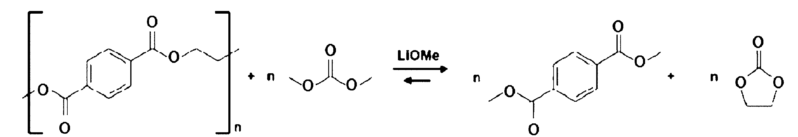
上述のレドックスシャトル反応は、特に、充電状態のリチウム2次電池を高温下で保存している際に顕著になると推測される。また、正極活物質が、一般式:LizNixCoyM1-x-yO2+α(ただし、0.5≦x≦1.0、0≦y≦0.35、0.9≦z≦1.3、-0.2≦α≦0.15、Mは、Mn、Al、V、Mg、Mo、Nb、Ti、Zr、Fe、Cu、Cr、Zn、F、及びBからなる群より選ばれる1種以上の元素である。)で表される化合物である場合、上述のレドックスシャトル反応がより顕著になると推測される。 It is speculated that the above-mentioned redox shuttle reaction becomes more prominent when a charged lithium secondary battery is stored at high temperature. In addition, when the positive electrode active material is a compound represented by the general formula: Li z Ni x Co y M 1-x-y O 2 + α (wherein 0.5≦x≦1.0, 0≦y≦0.35, 0.9≦z≦1.3, −0.2≦α≦0.15, M is one or more elements selected from the group consisting of Mn, Al, V, Mg, Mo, Nb, Ti, Zr, Fe, Cu, Cr, Zn, F, and B), it is speculated that the above-mentioned redox shuttle reaction becomes more prominent.
上述のレドックスシャトル反応により、電解液成分の組成が変化し、且つ、電解液成分の質量が減少するため、容量残存率等のリチウム2次電池の性能が劣化すると推測される。なお、上述のレドックスシャトル反応は、ジメチルカーボネートに限らず、エチルメチルカーボネート及びエチレンカーボネート等の鎖状カーボネート、並びにジメトキシエタン、ジエトキシエタン、ジメトキシプロパン、ジメトキシブタン、及びジエチレングリコールジメチルエーテル等の鎖状エーテルにおいても発生すると推測される。 The above-mentioned redox shuttle reaction changes the composition of the electrolyte components and reduces the mass of the electrolyte components, which is presumably degrading the performance of the lithium secondary battery, such as the remaining capacity rate. Note that the above-mentioned redox shuttle reaction is presumed to occur not only in dimethyl carbonate, but also in chain carbonates such as ethyl methyl carbonate and ethylene carbonate, and chain ethers such as dimethoxyethane, diethoxyethane, dimethoxypropane, dimethoxybutane, and diethylene glycol dimethyl ether.
ここで、ビニレンカーボネートを電解液に添加剤として添加することにより、ビニレンカーボネートが負極で分解し、負極に被膜を生成し、負極において上述のレドックスシャトル反応が発生することを抑制すると推測される。また、ジフルオロリン酸リチウムを電解液に添加剤として添加することにより、ジフルオロリン酸リチウムが正極で分解し、正極に被膜を生成し、正極において上述のレドックスシャトル反応が発生することを抑制すると推測される。その結果、電解液成分の組成が変化し、質量が減少することを抑制できると推測される。したがって、充電状態のリチウム2次電池を高温下で保存した場合にも、容量残存率等のリチウム2次電池の高い性能を維持できると推測される。 Here, it is speculated that by adding vinylene carbonate as an additive to the electrolyte, the vinylene carbonate decomposes at the negative electrode, forming a film on the negative electrode, and inhibiting the above-mentioned redox shuttle reaction from occurring at the negative electrode. Also, it is speculated that by adding lithium difluorophosphate as an additive to the electrolyte, the lithium difluorophosphate decomposes at the positive electrode, forming a film on the positive electrode, and inhibiting the above-mentioned redox shuttle reaction from occurring at the positive electrode. As a result, it is speculated that it is possible to inhibit the composition of the electrolyte components from changing and the mass from decreasing. Therefore, it is speculated that the high performance of the lithium secondary battery, such as the capacity retention rate, can be maintained even when a charged lithium secondary battery is stored at high temperatures.
したがって、本実施形態のリチウム2次電池は、高い安全性、高温における優れた性能安定性を両立させることが可能になると考えられる。但し、その要因は上述のものに限定されない。 Therefore, it is believed that the lithium secondary battery of this embodiment can achieve both high safety and excellent performance stability at high temperatures. However, the factors behind this are not limited to those mentioned above.
1.1.正極
本実施形態の正極30は、正極集電体32と正極活物質層34とを有する。
1.1 Positive Electrode The positive electrode 30 of the present embodiment includes a positive electrode
アノードフリー型電池の正極30の平均厚さは、特に限定されないが、例えば、20μm以上100μm以下であり、30μm以上80μm以下であり、40μm以上70μm以下である。ただし、正極30の平均厚さは、所望する電池の容量に応じて適宜調整することができる。 The average thickness of the positive electrode 30 of the anode-free battery is not particularly limited, but is, for example, 20 μm to 100 μm, 30 μm to 80 μm, or 40 μm to 70 μm. However, the average thickness of the positive electrode 30 can be adjusted appropriately depending on the desired battery capacity.
1.1.1.正極集電体
本実施形態の正極集電体32は、ポリエチレンテレフタラートを含む樹脂層320と、当該樹脂層320の両面に設けられた金属層322とを備える集電体フィルムを有してもよく、樹脂層320を有さず金属層322を有してもよい。集電体フィルムを備える場合、金属層322は、樹脂層320の両側の表面に、蒸着、スパッタリング、電解めっき、又は接着剤などで貼り合わせることで形成される。
The positive electrode
1.1.1.1.樹脂層
本実施形態の正極集電体32の樹脂層320は、絶縁体であり、当該樹脂層320の両面に設けられた金属層322同士が導通することを防止する。樹脂層320を構成する樹脂は、特に限定されないが、例えば、シート状(フィルム状)又は繊維状の樹脂で構成されてもよい。樹脂としては、ポリエチレンテレフタラート(PET)を含み、その他の樹脂を更に含んでもよい。その他の樹脂としては、ポリエチレン、ポリプロピレン等のポリオレフィン樹脂、ポリスチレン、ポリ塩化ビニル又はポリアミド等の熱可塑性樹脂が挙げられる。その他の樹脂は、1種単独で、又は2種以上を組み合わせて用いてもよい。
1.1.1.1. Resin layer The
樹脂層320は、上述の樹脂のほか、所望の物性に応じて適宜その他の添加剤を含んでもよい。添加剤としては、特に限定されないが、例えば、着色剤、難燃剤、界面活性剤等が挙げられる。
In addition to the resins described above, the
樹脂の含有量は、特に限定されないが、例えば、樹脂層320の総量に対して、60質量%以上100質量%以下であってよく、80質量%以上100質量%以下であってよく、90質量%以上100質量%以下であってよく、95質量%以上100質量%以下であってよく、100質量%であってよい。
The resin content is not particularly limited, but may be, for example, 60% by mass or more and 100% by mass or less, 80% by mass or more and 100% by mass or less, 90% by mass or more and 100% by mass or less, 95% by mass or more and 100% by mass or less, or 100% by mass, relative to the total amount of the
PETの含有量は、特に限定されないが、例えば、樹脂層320の総量に対して、60質量%以上100質量%以下であってよく、80質量%以上100質量%以下であってよく、90質量%以上100質量%以下であってよく、95質量%以上100質量%以下であってよく、100質量%であってよい。
The amount of PET contained is not particularly limited, but may be, for example, 60% by mass or more and 100% by mass or less, 80% by mass or more and 100% by mass or less, 90% by mass or more and 100% by mass or less, 95% by mass or more and 100% by mass or less, or 100% by mass, relative to the total amount of the
PETの含有量は、特に限定されないが、例えば、樹脂の総量に対して、80質量%以上100質量%以下であってよく、85質量%以上100質量%以下であってよく、90質量%以上100質量%以下であってよく、95質量%以上100質量%以下であってよく、98質量%以上100質量%以下であってよく、100質量%であってよい。 The amount of PET is not particularly limited, but may be, for example, 80% by mass or more and 100% by mass or less, 85% by mass or more and 100% by mass or less, 90% by mass or more and 100% by mass or less, 95% by mass or more and 100% by mass or less, 98% by mass or more and 100% by mass or less, or 100% by mass, relative to the total amount of resin.
樹脂層320の厚さは、特に限定されないが、例えば、2μm以上15μm以下であり、3μm以上12μm以下であり、4μm以上10μm以下である。
The thickness of the
1.1.1.2.金属層
本実施形態の正極集電体32の金属層322は、正極活物質層34に物理的及び/又は電気的に接触し、正極活物質層34に対して電子を授受するように機能する。金属層322は、電池においてリチウムと反応しない金属などの導電体から構成される。金属層322を構成する金属としては、特に限定されないが、アルミニウム、チタン、ステンレス、ニッケル及びこれらの合金からなる群から選択される少なくとも一種である。このなかでも、アルミニウム又はアルミニウム合金が好ましく、アルミニウムが特に好ましい。金属としては、1種単独で、又は2種以上を組み合わせて用いてもよい。なお、本明細書中、「リチウムと反応しない金属」とは、リチウム2次電池の動作条件においてリチウムイオン又はリチウム金属と反応して合金化することがない金属を意味する。
1.1.1.2. Metal layer The
正極集電体32が集電体フィルムを有するとき、金属層322の厚さは、特に限定されないが、例えば、0.1μm以上4.0μm以下であり、0.2μm以上3.0μm以下であり、0.3μm以上2.5μm以下であり、0.4μm以上2.0μm以下である。
When the
正極集電体32が、樹脂層320を有さず金属層322を有するとき、金属層322の厚さは、特に限定されないが、例えば、4.0μm以上20.0μm以下であり、6.0μm以上17.5μm以下であり、8.0μm以上15.0μm以下である。
When the
1.1.2.正極活物質
本実施形態の正極活物質は、特に限定されないが、例えば、バインダー、導電助剤、犠牲正極剤、その他の添加剤を含む正極活物質組成物に含まれ、正極活物質組成物が、正極集電体32上の少なくとも一面、又は、両面に塗布され、プレス成形されることにより、正極活物質層34が、正極集電体32上の少なくとも一面、又は両面に配置される。
The positive electrode active material of the present embodiment is not particularly limited, but is, for example, contained in a positive electrode active material composition including a binder, a conductive assistant, a sacrificial positive electrode agent, and other additives. The positive electrode active material composition is applied to at least one surface or both surfaces of the positive electrode
正極集電体32上に正極活物質層34を配置する方法としては、プレス成形に限定されず、例えば、正極活物質組成物に熱硬化性化合物を含ませて加熱することで硬化させる方法、正極活物質組成物に光硬化性化合物を含ませて光照射することで硬化させる方法、正極活物質組成物を2液硬化型組成物として、2液混合することで硬化させる方法、等が挙げられる。
The method of disposing the positive electrode
本実施形態の正極活物質層34は、一般式:LizNixCoyM1-x-yO2+α(ただし、0.5≦x≦1.0、0≦y≦0.35、0.9≦z≦1.3、-0.2≦α≦0.15、Mは、Mn、Al、V、Mg、Mo、Nb、Ti、Zr、Fe、Cu、Cr、Zn、F、及びBからなる群より選ばれる1種以上の元素である。)で表される化合物を1種以上含む。
The positive electrode
また、好ましくは、正極活物質層34は、一般式:LizNixCoyM1-x-yO2+α(ただし、0.7≦x≦1.0、0≦y≦0.35、0.9≦z≦1.3、-0.2≦α≦0.15、Mは、Mn、Al、V、Mg、Mo、Nb、Ti、Zr、Fe、Cu、Cr、Zn、F、及びBからなる群より選ばれる1種以上の元素である。)で表される化合物を1種以上含む。ニッケル比率が高い上述の化合物を正極活物質として含むことにより、リチウム2次電池のエネルギー密度がより向上する傾向にある。また、ニッケル比率が高くなると、上述のレドックスシャトル反応がより起こりやすくなるが、電解液が下記で詳説する添加剤を含むことにより、該反応を抑制し、高温における優れた性能安定性を有する傾向にある。
Also, preferably, the positive electrode
正極活物質としては、上述の化合物以外の、その他の正極活物質を含んでもよい。正極活物質とは、正極において電極反応、すなわち酸化反応及び還元反応を生じる物質である。具体的には、本実施形態のその他の正極活物質としてはリチウム元素(典型的には、リチウムイオン)のホスト物質が挙げられる。そのようなその他の正極活物質としては、特に限定されないが、例えば、金属酸化物及び金属リン酸塩が挙げられる。上記金属酸化物としては、特に限定されないが、例えば、酸化コバルト系化合物、酸化マンガン系化合物、及び酸化ニッケル系化合物等が挙げられる。上記金属リン酸塩としては、特に限定されないが、例えば、リン酸鉄系化合物、及びリン酸コバルト系化合物が挙げられる。典型的なその他の正極活物質としては、LiCoO2、LiNixMnyO(x+y=1)、LiNiO2、LiMn2O4、LiFePO、LiCoPO、LiFeOF、LiNiOF、及びTiS2が挙げられる。その他の正極活物質は、1種単独で、又は2種以上を組み合わせて用いてもよい。 The positive electrode active material may include other positive electrode active materials other than the above-mentioned compounds. The positive electrode active material is a material that causes an electrode reaction, i.e., an oxidation reaction and a reduction reaction, at the positive electrode. Specifically, the other positive electrode active material of this embodiment may include a host material of a lithium element (typically, a lithium ion). Such other positive electrode active materials include, but are not limited to, metal oxides and metal phosphates. The metal oxides include, but are not limited to, cobalt oxide-based compounds, manganese oxide-based compounds, and nickel oxide-based compounds. The metal phosphates include, but are not limited to, iron phosphate-based compounds, and cobalt phosphate-based compounds. Typical other positive electrode active materials include LiCoO 2 , LiNi x Mn y O (x + y = 1), LiNiO 2 , LiMn 2 O 4 , LiFePO, LiCoPO, LiFeOF, LiNiOF, and TiS 2 . The other positive electrode active materials may be used alone or in combination of two or more.
正極活物質の含有量は、正極活物質組成物の総量に対して、特に限定されないが、例えば、60質量%以上100質量%以下であり、70質量%以上99質量%以下であり、80質量%以上98質量%以下であり、85質量%以上97質量%以下であり、90質量%以上96質量%以下である。 The amount of the positive electrode active material relative to the total amount of the positive electrode active material composition is not particularly limited, but may be, for example, 60% by mass or more and 100% by mass or less, 70% by mass or more and 99% by mass or less, 80% by mass or more and 98% by mass or less, 85% by mass or more and 97% by mass or less, or 90% by mass or more and 96% by mass or less.
1.1.3.バインダー
本実施形態の正極活物質組成物は、バインダーを含んでもよい。バインダーを含むことにより、正極活物質層34が正極集電体32により結着しやすくなり、また、正極活物質層34を正極集電体32上に配置した後に、柔軟性が向上する。
The positive electrode active material composition of the present embodiment may contain a binder. By containing a binder, the positive electrode
本実施形態のバインダーとしては、特に限定されないが、例えば、ポリビニリデンフロライド;ポロビニリデンフロライドに水酸基、アミノ基、カルボニル基、カルボキシル基、フェニル基、メチル基等の官能基を導入した変性ポリビニリデンフロライド;ポリテトラフルオロエチレン;ポリテトラフルオロエチレンに水酸基、アミノ基、カルボニル基、カルボキシル基、フェニル基、メチル基等の官能基を導入した変性ポリテトラフルオロエチレン;テトラフルオロエチレンを構成単位として有するブロック共重合体、ランダム共重合体、又はグラフト共重合体;スチレンブタジエンゴム;カルボキシメチルセルロース;アクリル樹脂;ポリイミド樹脂等が挙げられる。バインダーは、1種単独で、又は2種以上を組み合わせて用いてもよい。 The binder of this embodiment is not particularly limited, but examples thereof include polyvinylidene fluoride; modified polyvinylidene fluoride obtained by introducing functional groups such as hydroxyl groups, amino groups, carbonyl groups, carboxyl groups, phenyl groups, and methyl groups into polyvinylidene fluoride; polytetrafluoroethylene; modified polytetrafluoroethylene obtained by introducing functional groups such as hydroxyl groups, amino groups, carbonyl groups, carboxyl groups, phenyl groups, and methyl groups into polytetrafluoroethylene; block copolymers, random copolymers, and graft copolymers having tetrafluoroethylene as a constituent unit; styrene butadiene rubber; carboxymethyl cellulose; acrylic resins; polyimide resins, and the like. The binder may be used alone or in combination of two or more types.
バインダーの含有量は、正極活物質組成物の総量に対して、特に限定されないが、例えば、0.5質量%以上10.0質量%以下であり、1.0質量%以上8.0質量%以下であり、2.0質量%以上6.0質量%以下である。 The amount of binder contained is not particularly limited relative to the total amount of the positive electrode active material composition, but is, for example, 0.5% by mass to 10.0% by mass, 1.0% by mass to 8.0% by mass, or 2.0% by mass to 6.0% by mass.
1.1.4.導電助剤
本実施形態の正極活物質組成物は、導電助剤を含んでもよい。導電助剤としては、特に限定されないが、例えば、カーボンブラック、シングルウォールカーボンナノチューブ(SWCNT)、マルチウォールカーボンナノチューブ(MWCNT)、カーボンナノファイバー(CF)、及びアセチレンブラックが挙げられる。導電助剤は、1種単独で、又は2種以上を組み合わせて用いてもよい。
1.1.4. Conductive assistant The positive electrode active material composition of the present embodiment may contain a conductive assistant. The conductive assistant is not particularly limited, but may be, for example, carbon black, single-walled carbon nanotube (SWCNT), multi-walled carbon nanotube (MWCNT), carbon nanofiber (CF), and acetylene black. The conductive assistant may be used alone or in combination of two or more kinds.
導電助剤の含有量は、正極活物質組成物の総量に対して、特に限定されないが、例えば、0.5質量%以上30.0質量%未満である。 The amount of the conductive additive contained is not particularly limited, but is, for example, 0.5% by mass or more and less than 30.0% by mass relative to the total amount of the positive electrode active material composition.
1.1.5.犠牲正極剤
本実施形態の正極活物質組成物は、犠牲正極剤を含んでもよい。本実施形態の犠牲正極剤とは、正極活物質の充放電電位範囲において酸化反応を生じ、かつ、還元反応を実質的に生じないリチウム含有化合物である。正極が犠牲正極剤を含む場合、該正極を備えるリチウム2次電池を初期充電すると、正極活物質及び犠牲正極剤はリチウムイオンを放出すると共に酸化反応を生じ、外部回路を通じて負極に電子を放出する。その結果、正極活物質及び犠牲正極剤に由来するリチウムイオンは、負極の表面に析出する。また、そのようなリチウム2次電池を初期充電完了後に放電する(すなわち、初期放電する)と、負極表面に析出したリチウム金属が電解溶出し、外部回路を通じて負極から正極に電子が移動する。それに伴い、正極活物質は、リチウムイオンを受け取ると共に還元反応を生じる一方で、犠牲正極剤は、正極活物質の放電電位の範囲内では還元反応を実質的に生じず、酸化反応を生じる前の状態に戻ることが実質的に不可能である。したがって、上記リチウム2次電池を初期充電の後に放電させると、正極活物質に由来するリチウム金属が負極上から電解溶出するのに対し、犠牲正極剤に由来するリチウム金属は、そのほとんどが負極上に残留することとなり、電池の放電完了後においても、負極上に一部のリチウム金属が残留することとなる。当該残留リチウム金属は、初期放電に続く充電ステップにおいて、更なるリチウム金属が負極上に析出する際の足場となるため、初期放電後の充電ステップにおいてリチウム金属が負極上に均一に析出しやすくなる。その結果、リチウム2次電池はサイクル特性により優れる傾向にある。
1.1.5. Sacrificial Cathode Agent The positive electrode active material composition of this embodiment may contain a sacrificial cathode agent. The sacrificial cathode agent of this embodiment is a lithium-containing compound that undergoes an oxidation reaction in the charge/discharge potential range of the positive electrode active material and does not substantially undergo a reduction reaction. When the positive electrode contains a sacrificial cathode agent, when a lithium secondary battery including the positive electrode is initially charged, the positive electrode active material and the sacrificial cathode agent release lithium ions and undergo an oxidation reaction, and release electrons to the negative electrode through an external circuit. As a result, lithium ions derived from the positive electrode active material and the sacrificial cathode agent are deposited on the surface of the negative electrode. In addition, when such a lithium secondary battery is discharged after the initial charge is completed (i.e., initially discharged), the lithium metal deposited on the surface of the negative electrode is electrolytically dissolved, and electrons move from the negative electrode to the positive electrode through an external circuit. Accordingly, the positive electrode active material receives lithium ions and undergoes a reduction reaction, while the sacrificial cathode agent does not substantially undergo a reduction reaction within the range of the discharge potential of the positive electrode active material, and it is substantially impossible to return to the state before the oxidation reaction occurred. Therefore, when the lithium secondary battery is discharged after the initial charge, the lithium metal derived from the positive electrode active material is electrolytically dissolved from the negative electrode, whereas most of the lithium metal derived from the sacrificial positive electrode agent remains on the negative electrode, and even after the discharge of the battery is completed, some of the lithium metal remains on the negative electrode. The remaining lithium metal serves as a scaffold for further lithium metal to deposit on the negative electrode in the charging step following the initial discharge, so that the lithium metal is more likely to deposit uniformly on the negative electrode in the charging step following the initial discharge. As a result, the lithium secondary battery tends to have better cycle characteristics.
犠牲正極剤としては、特に限定されないが、例えば、Li2O2のようなリチウム酸化物;Li3Nのようなリチウム窒化物;Li2S-P2S5、Li2S-LiCl、Li2S-LiBr、及びLi2S-LiIのようなリチウム硫化物系固溶体;Li1+x(Ti1-yFey)1-xO2(0<x≦0.25、0.4<y≦0.9)、Li2-xTi1-zFezO3-y(0≦x<2、0≦y≦1、0.05≦z≦0.95)、Li5FeO4のような鉄系リチウム酸化物等が挙げられる。犠牲正極剤は、1種単独で、又は2種以上を組み合わせて用いてもよい。 Examples of the sacrificial positive electrode agent include, but are not limited to, lithium oxides such as Li 2 O 2 ; lithium nitrides such as Li 3 N; lithium sulfide solid solutions such as Li 2 S-P 2 S 5 , Li 2 S-LiCl, Li 2 S-LiBr, and Li 2 S-LiI; iron-based lithium oxides such as Li 1+x (Ti 1-y Fe y ) 1-x O 2 (0<x≦0.25, 0.4<y≦0.9), Li 2-x Ti 1-z Fe z O 3-y (0≦x<2, 0≦y≦1, 0.05≦z≦0.95), and Li 5 FeO 4. The sacrificial positive electrode agent may be used alone or in combination of two or more types.
犠牲正極剤の含有量は、正極活物質組成物の総量に対して、特に限定されないが、例えば、1.0質量%以上30.0質量%以下であり、2.0質量%以上20.0質量%以下であり、3.0質量%以上15.0質量%以下である。 The amount of the sacrificial positive electrode agent relative to the total amount of the positive electrode active material composition is not particularly limited, but may be, for example, 1.0% by mass or more and 30.0% by mass or less, 2.0% by mass or more and 20.0% by mass or less, or 3.0% by mass or more and 15.0% by mass or less.
また、正極活物質と犠牲正極剤の総量は、正極活物質組成物の総量に対して、特に限定されないが、例えば、60質量%以上100質量%以下であり、70質量%以上99質量%以下であり、80質量%以上98質量%以下であり、85質量%以上97質量%以下であり、90質量%以上96質量%以下である。 The total amount of the positive electrode active material and the sacrificial positive electrode agent is not particularly limited relative to the total amount of the positive electrode active material composition, but may be, for example, 60% by mass or more and 100% by mass or less, 70% by mass or more and 99% by mass or less, 80% by mass or more and 98% by mass or less, 85% by mass or more and 97% by mass or less, or 90% by mass or more and 96% by mass or less.
1.1.6.正極の製造方法
本実施形態の正極30は、特に限定されないが、例えば、以下のようにして製造する。樹脂層320の両側の表面に、蒸着、スパッタリング、電解めっき、又は接着剤によって貼り合わせることで金属層322を形成して集電体フィルムを形成し、本実施形態の正極集電体32を得る。そして、必要に応じて、上述した正極活物質と、バインダーと、犠牲正極剤と、その他の添加剤とを混合し、正極活物質組成物を得る。正極活物質又は得られた正極活物質組成物を、上記正極集電体32の両面又は片面に塗布し、プレス成形して、正極集電体32の両面又は片面に正極活物質層34を形成し、成型体を得る。得られた成形体を打ち抜き加工により、所定のサイズに打ち抜き、本実施形態の正極30を得る。
1.1.6. Method for Producing Positive Electrode The positive electrode 30 of the present embodiment is produced, for example, as follows, but is not particularly limited. A
また、上述の製造方法において、集電体フィルムを有する正極集電体32の代わりに、樹脂層320を有さず金属層322を有する正極集電体32を用いることも可能である。
In addition, in the above-mentioned manufacturing method, it is also possible to use a
1.2.負極
本実施形態の負極10は、負極集電体12を有する。
1.2 Negative Electrode The negative electrode 10 of this embodiment has a negative electrode
1.2.1.負極集電体
本実施形態の負極集電体12は、ポリエチレンテレフタラートを含む樹脂層120と、当該樹脂層120の両面に設けられた金属層122とを備える集電体フィルムを有してもよく、樹脂層120を有さず金属層122を有してもよい。集電体フィルムを備える場合、金属層122は、樹脂層120の両側の表面に、蒸着、スパッタリング、電解めっき、又は接着剤などで貼り合わせることで形成される。
The negative electrode
1.2.1.1.樹脂層
本実施形態の負極集電体12の樹脂層120は、絶縁体であり、当該樹脂層120の両面に設けられた金属層122同士が導通することを防止する。樹脂層120を構成する樹脂は、特に限定されないが、例えば、シート状(フィルム状)又は繊維状の樹脂で構成されてもよい。樹脂としては、ポリエチレンテレフタラート(PET)を含み、その他の樹脂を更に含んでもよい。その他の樹脂としては、正極集電体32の樹脂層320と同様のものが挙げられる。また、樹脂層120は、上述の樹脂のほか、所望の物性に応じて適宜その他の添加剤を含んでもよく、その他の添加剤としては、正極集電体32の樹脂層320と同様のものが挙げられる。
1.2.1.1. Resin layer The
樹脂の含有量及びPETの含有量は、正極集電体32における樹脂の含有量及びPETの含有量と同様であってよい。
The resin content and PET content may be the same as the resin content and PET content in the positive electrode
樹脂層120の厚さは、正極集電体32における樹脂層320の厚さと同様であってよい。
The thickness of the
1.2.1.2.金属層
本実施形態の負極集電体12の金属層122を構成する金属としては、集電体として用いることができるものであれば特に限定されず、例えば、銅、ニッケル、チタン、鉄、その他リチウムと反応しない金属、及びこれらの合金、並びにステンレス鋼(SUS)からなる群より選択される少なくとも1種からなるものが挙げられ、好ましくは、銅、ニッケル、及びこれらの合金、並びにSUSからなる群より選択される少なくとも1種からなるものが挙げられる。
1.2.1.2. Metal Layer The metal constituting the
負極集電体12が集電体フィルムを有するとき、金属層122の厚さは、集電体フィルムを有する正極集電体32における金属層322の厚さと同様であってよい。
When the negative electrode
負極集電体12が、樹脂層120を有さず金属層122を有するとき、金属層122の厚さは、樹脂層320を有さず金属層322を有する正極集電体32における金属層322の厚さと同様であってよい。
When the negative electrode
1.2.2.負極活物質
負極活物質とは、負極において電極反応、すなわち酸化反応及び還元反応を生じる物質である。具体的には、本実施形態の負極活物質としては、リチウム金属、及びリチウム元素(リチウムイオン又はリチウム金属)のホスト物質が挙げられる。リチウム元素のホスト物質とは、リチウムイオン又はリチウム金属を負極に保持するために設けられる物質を意味する。そのような保持の機構としては、例えば、インターカレーション、合金化、及び金属クラスターの吸蔵等が挙げられ、典型的には、インターカレーションである。
1.2.2. Negative electrode active material The negative electrode active material is a material that causes an electrode reaction, i.e., an oxidation reaction and a reduction reaction, at the negative electrode. Specifically, the negative electrode active material of this embodiment includes a host material of lithium metal and lithium element (lithium ion or lithium metal). The host material of lithium element means a material provided to hold lithium ion or lithium metal at the negative electrode. Examples of such a holding mechanism include intercalation, alloying, and metal cluster occlusion, and typically, intercalation.
負極活物質としては、特に限定されないが、例えば、リチウム金属及びリチウム金属を含む合金、炭素系物質、金属酸化物、並びにリチウムと合金化する金属及び該金属を含む合金等が挙げられる。上記炭素系物質としては、特に限定されず、例えば、グラフェン、グラファイト、ハードカーボン、カーボンナノチューブ等が挙げられる。上記金属酸化物としては、特に限定されず、例えば、酸化チタン系化合物、酸化コバルト系化合物等が挙げられる。上記リチウムと合金化する金属としては、特に限定されず、例えば、ケイ素、ゲルマニウム、スズ、鉛、アルミニウム、及びガリウムが挙げられる。 The negative electrode active material is not particularly limited, but examples thereof include lithium metal and alloys containing lithium metal, carbon-based materials, metal oxides, metals that alloy with lithium and alloys containing said metals, etc. The carbon-based materials are not particularly limited, but examples thereof include graphene, graphite, hard carbon, carbon nanotubes, etc. The metal oxides are not particularly limited, but examples thereof include titanium oxide-based compounds and cobalt oxide-based compounds, etc. The metals that alloy with lithium are not particularly limited, but examples thereof include silicon, germanium, tin, lead, aluminum, and gallium.
本実施形態のアノードフリー型リチウム2次電池は、その負極10が、負極活物質を有しない負極集電体12からなるものであり、電解液として後述のものを用いる。
The anode-free lithium secondary battery of this embodiment has a negative electrode 10 made of a negative electrode
アノードフリー型電池は、電池の初期充電前において、負極10が負極活物質を有せず、負極集電体12のみからなる。よって、その初期充電後に、負極10上にリチウム金属が析出し、及び、その析出したリチウム金属が電解溶出することにより充放電が行われる。したがって、アノードフリー型電池は、負極活物質が占める体積及び負極活物質の質量が削減され、電池全体の体積及び質量が小さくなるため、エネルギー密度が原理的に高いという利点がある。
In an anode-free battery, before the initial charge of the battery, the negative electrode 10 does not have any negative electrode active material and consists only of the negative electrode
本明細書のアノードフリー型電池において、負極が「負極活物質を有しない」とは、負極が負極活物質を有しないか、実質的に有しないことを意味する。負極が負極活物質を実質的に有しないとは、負極における負極活物質の含有量が、負極全体に対して10.0質量%以下であることを意味する。アノードフリー型電池の負極10における負極活物質の含有量は、負極10全体に対して、好ましくは、5.0質量%以下であり、1.0質量%以下であり、0.1質量%以下であり、0.0質量%である。負極10が負極活物質を有せず、又は、負極10における負極活物質の含有量が上記の範囲内にあることにより、リチウム2次電池のエネルギー密度が高いものとなる。 In the anode-free battery of this specification, the negative electrode "has no negative electrode active material" means that the negative electrode does not have or substantially does not have a negative electrode active material. The negative electrode substantially does not have a negative electrode active material means that the content of the negative electrode active material in the negative electrode is 10.0 mass% or less with respect to the entire negative electrode. The content of the negative electrode active material in the negative electrode 10 of the anode-free battery is preferably 5.0 mass% or less, 1.0 mass% or less, 0.1 mass% or less, or 0.0 mass% with respect to the entire negative electrode 10. When the negative electrode 10 has no negative electrode active material or the content of the negative electrode active material in the negative electrode 10 is within the above range, the energy density of the lithium secondary battery is high.
また、本明細書のアノードフリー型電池において、電池が「初期充電前である」とは、電池が組み立てられてから第1回目の充電をするまでの状態を意味する。また、電池が「放電終了時である」とは、電池の電圧が、好ましくは、1.0V以上3.8V以下であり、1.0V以上3.0V以下である状態を意味する。 In addition, in the anode-free battery of this specification, when the battery is "before the initial charge" it means the state from when the battery is assembled until the first charge. Also, when the battery is "at the end of discharge" it means the state in which the battery voltage is preferably 1.0 V or more and 3.8 V or less, and more preferably 1.0 V or more and 3.0 V or less.
本実施形態のアノードフリー型電池は、電池の電圧が1.0V以上3.5V以下である場合において、リチウム金属の含有量が、負極10全体に対して、10.0質量%以下であってもよく(好ましくは、5.0質量%以下であり、1.0質量%以下である。);電池の電圧が1.0V以上3.0V以下である場合において、リチウム金属の含有量が、負極10全体に対して、10.0質量%以下であってもよく(好ましくは、5.0質量%以下であり、1.0質量%以下である。);又は、電池の電圧が1.0V以上2.5V以下である場合において、リチウム金属の含有量が、負極10全体に対して、10.0質量%以下であってもよい(好ましくは、5.0質量%以下であり、1.0質量%以下であってもよい。)。 In the anode-free battery of this embodiment, when the battery voltage is 1.0 V or more and 3.5 V or less, the lithium metal content may be 10.0 mass % or less (preferably 5.0 mass % or less, 1.0 mass % or less) relative to the entire negative electrode 10; when the battery voltage is 1.0 V or more and 3.0 V or less, the lithium metal content may be 10.0 mass % or less (preferably 5.0 mass % or less, 1.0 mass % or less) relative to the entire negative electrode 10; or when the battery voltage is 1.0 V or more and 2.5 V or less, the lithium metal content may be 10.0 mass % or less (preferably 5.0 mass % or less, 1.0 mass % or less) relative to the entire negative electrode 10.
また、本実施形態のアノードフリー型電池において、電池の電圧が4.2Vの状態において負極10上に析出しているリチウム金属の質量M4.2に対する、電池の電圧が3.0Vの状態において負極10上に析出しているリチウム金属の質量M3.0の比M3.0/M4.2は、好ましくは、40.0%以下であり、38.0%以下であり、35.0%以下である。比M3.0/M4.2は、1.0%以上であってもよく、2.0%以上であってもよく、3.0%以上であってもよく、4.0%以上であってもよい。 In the anode-free battery of this embodiment, the ratio M3.0/ M4.2 of the mass M3.0 of lithium metal deposited on the negative electrode 10 when the battery voltage is 3.0 V to the mass M4.2 of lithium metal deposited on the negative electrode 10 when the battery voltage is 4.2 V is preferably 40.0 % or less, 38.0% or less, or 35.0% or less. The ratio M3.0 / M4.2 may be 1.0% or more, 2.0% or more, 3.0% or more , or 4.0% or more.
アノードフリー型電池の負極10の平均厚さは、特に限定されないが、例えば、3.0μm以上30.0μm以下である。アノードフリー型電池における負極10の占める体積を減少させ、エネルギー密度を向上させる観点から、負極10の平均厚さは、好ましくは、4.0μm以上20.0μm以下であり、5.0μm以上18.0μm以下であり、6.0μm以上15μm以下である。 The average thickness of the negative electrode 10 of the anode-free battery is not particularly limited, but is, for example, 3.0 μm or more and 30.0 μm or less. From the viewpoint of reducing the volume occupied by the negative electrode 10 in the anode-free battery and improving the energy density, the average thickness of the negative electrode 10 is preferably 4.0 μm or more and 20.0 μm or less, 5.0 μm or more and 18.0 μm or less, or 6.0 μm or more and 15 μm or less.
1.2.3.負極の製造方法
本実施形態の負極10は、特に限定されないが、例えば、以下のようにして製造する。樹脂層120の両側の表面に、蒸着、スパッタリング、電解めっき、又は接着剤によって貼り合わせることで金属層122を形成して集電体フィルムを形成し、本実施形態の負極集電体12を得る。アノードフリー型リチウム2次電池においては、負極活物質を有しないため、上記負極集電体12をもって本実施形態の負極10とすることができる。
1.2.3. Method for Manufacturing Negative Electrode The negative electrode 10 of the present embodiment is manufactured, for example, as follows, without any particular limitation. A
また、上述の製造方法において、集電体フィルムを有する負極集電体12の代わりに、樹脂層120を有さず金属層122を有する負極集電体12を用いることも可能である。
In addition, in the above-mentioned manufacturing method, it is also possible to use a
1.3.セパレータ
本実施形態のセパレータ20としては、正極30と負極10とを物理的及び/又は電気的に隔離する機能、及びリチウムイオンのイオン伝導性を確保する機能を有するものであれば、特に限定されない。そのようなものとしては、例えば、絶縁性の多孔質部材、ポリマー電解質、ゲル電解質、及び無機固体電解質が挙げられ、典型的には絶縁性を有する多孔質の部材、ポリマー電解質、及びゲル電解質からなる群より選択される少なくとも1種が挙げられる。また、セパレータ20として、1種の部材を単独で用いてもよく、2種以上の部材を組み合わせて用いてもよい。
1.3. Separator The
セパレータ20としては、好ましくは絶縁性の多孔質部材、ポリマー電解質、又はゲル電解質を1種単独で又は2種以上を組み合わせて用いる。なお、セパレータ20として絶縁性の多孔質部材を単独で用いる場合、リチウム2次電池は電解液を更に備える必要がある。
As the
上記のポリマー電解質としては、特に限定されないが、例えば高分子及び電解質を主に含む固体ポリマー電解質、並びに高分子、電解質、及び可塑剤を主に含む半固体ポリマー電解質が挙げられる。
上記のゲル電解質としては、特に限定されないが、例えば高分子及び液体電解質(すなわち、溶媒と電解質)を主に含むものが挙げられる。
The polymer electrolyte is not particularly limited, but examples thereof include solid polymer electrolytes mainly containing a polymer and an electrolyte, and semi-solid polymer electrolytes mainly containing a polymer, an electrolyte, and a plasticizer.
The gel electrolyte is not particularly limited, but may be, for example, one that mainly contains a polymer and a liquid electrolyte (i.e., a solvent and an electrolyte).
ポリマー電解質及びゲル電解質が含み得る高分子としては、特に限定されないが、例えばエーテル及びエステル等の酸素原子を含む官能基、ハロゲン基、並びにシアノ基のような極性基を含む高分子が挙げられる。具体的には、ポリエチレンオキサイド(PEO)のような主鎖及び/又は側鎖にエチレンオキサイドユニットを有する樹脂、ポリプロピレンオキサイド(PPO)のような主鎖及び/又は側鎖にプロピレンオキサイドユニットを有する樹脂、アクリル樹脂、ビニル樹脂、エステル樹脂、ナイロン樹脂、ポリビニリデンフロライド(PVdF)、ポリアクリロニトリル(PAN)、ポリシロキサン、ポリホスファゼン、ポリメタクリル酸メチル、ポリアミド、ポリイミド、アラミド、ポリ乳酸、ポリウレタン、ポリアセタール、ポリスルホン、ポリエチレンカーボネート、ポリプロピレンカーボネート、及びポリテトラフロロエチレンが挙げられる。上記のような樹脂は、1種単独で、又は2種以上を組み合わせて用いてもよい。 Polymers that may be included in the polymer electrolyte and gel electrolyte include, but are not limited to, polymers containing functional groups containing oxygen atoms such as ethers and esters, halogen groups, and polar groups such as cyano groups. Specific examples include resins having ethylene oxide units in the main chain and/or side chains such as polyethylene oxide (PEO), resins having propylene oxide units in the main chain and/or side chains such as polypropylene oxide (PPO), acrylic resins, vinyl resins, ester resins, nylon resins, polyvinylidene fluoride (PVdF), polyacrylonitrile (PAN), polysiloxane, polyphosphazene, polymethylmethacrylate, polyamide, polyimide, aramid, polylactic acid, polyurethane, polyacetal, polysulfone, polyethylene carbonate, polypropylene carbonate, and polytetrafluoroethylene. The above resins may be used alone or in combination of two or more.
ポリマー電解質及びゲル電解質に含まれる電解質としては、Li、Na、K、Ca、及びMgの塩等が挙げられる。典型的には本実施形態において、ポリマー電解質及びゲル電解質はリチウム塩を含む。
リチウム塩としては、特に限定されないが、例えば、LiI、LiCl、LiBr、LiF、LiBF4、LiPF6、LiAsF6、LiSO3CF3、LiN(SO2F)2、LiN(SO2CF3)2、LiN(SO2CF3CF3)2、LiB(O2C2H4)2、LiB(C2O4)2、LiB(O2C2H4)F2、LiB(OCOCF3)4、LiNO3、及びLi2SO4が挙げられ、好ましくはLiPF6、LiN(SO2F)2、LiN(SO2CF3)2、及びLiN(SO2CF3CF3)2からなる群より選択される少なくとも1種である。上記のような塩、又はリチウム塩は、1種単独で、又は2種以上を組み合わせて用いてもよい。
The electrolyte contained in the polymer electrolyte and the gel electrolyte includes salts of Li, Na, K, Ca, and Mg, etc. Typically, in this embodiment, the polymer electrolyte and the gel electrolyte include a lithium salt.
The lithium salt is not particularly limited, but examples thereof include LiI, LiCl, LiBr , LiF, LiBF4 , LiPF6, LiAsF6 , LiSO3CF3 , LiN ( SO2F ) 2 , LiN ( SO2CF3 ) 2 , LiN( SO2CF3CF3)2, LiB(O2C2H4)2, LiB(C2O4)2 , LiB ( O2C2H4 ) F2 , LiB ( OCOCF3 ) 4 , LiNO3 , and Li2SO4 , and preferably LiPF6 , LiN( SO2F ) 2 , LiN( SO2 The salt is at least one selected from the group consisting of LiN(SO 2 CF 3 CF 3 ) 2 , and LiN(SO 2 CF 3 CF 3 ) 2. The above-mentioned salts or lithium salts may be used alone or in combination of two or more.
ポリマー電解質及びゲル電解質における高分子とリチウム塩との配合比は、高分子の有する極性基と、リチウム塩の有するリチウム原子の比によって定めてもよい。例えば高分子が酸素原子を有する場合、高分子の有する酸素原子の数と、リチウム塩の有するリチウム原子の数の比([Li]/[O])によって定めてもよい。ポリマー電解質及びゲル電解質において、高分子とリチウム塩との配合比は、上記比([Li]/[O])が、例えば、0.02以上0.20以下、0.03以上0.15以下、又は0.04以上0.12以下になるように調整することができる。 The compounding ratio of the polymer and the lithium salt in the polymer electrolyte and the gel electrolyte may be determined by the ratio of the polar group of the polymer to the lithium atoms of the lithium salt. For example, when the polymer has oxygen atoms, it may be determined by the ratio ([Li]/[O]) of the number of oxygen atoms of the polymer to the number of lithium atoms of the lithium salt. In the polymer electrolyte and the gel electrolyte, the compounding ratio of the polymer and the lithium salt can be adjusted so that the ratio ([Li]/[O]) is, for example, 0.02 or more and 0.20 or less, 0.03 or more and 0.15 or less, or 0.04 or more and 0.12 or less.
ゲル電解質に含まれる溶媒としては、特に限定されないが、例えば後述する電解液に含まれ得る溶媒を、1種単独で又は2種以上を組み合わせて用いることができる。好ましい溶媒の例についても後述する電解液におけるものと同様である。
半固体ポリマー電解質に含まれる可塑剤としては、特に限定されないが、例えばゲル電解質に含まれ得る溶媒と同様の成分、及び種々のオリゴマーが挙げられる。
The solvent contained in the gel electrolyte is not particularly limited, but for example, the solvents that can be contained in the electrolyte solution described later can be used alone or in combination of two or more. Examples of preferred solvents are the same as those in the electrolyte solution described later.
The plasticizer contained in the semi-solid polymer electrolyte is not particularly limited, but may include, for example, components similar to the solvent that may be contained in the gel electrolyte, and various oligomers.
セパレータ20が絶縁性の多孔質部材を含む場合、かかる部材の細孔にイオン伝導性を有する物質が充填されることにより、かかる部材はイオン伝導性を発揮する。よって、本実施形態においては、例えば本実施形態の電解液、及び本実施形態の電解液を含むゲル電解質等が充填される。
When the
絶縁性の多孔質部材を構成する材料としては、特に限定されず、例えば絶縁性高分子材料が挙げられ、具体的には、ポリエチレン(PE)、及びポリプロピレン(PP)が挙げられる。すなわち、セパレータ20は、多孔質のポリエチレン(PE)膜、多孔質のポリプロピレン(PP)膜、又はこれらの積層構造であってよい。
The material constituting the insulating porous member is not particularly limited, and examples thereof include insulating polymeric materials, specifically, polyethylene (PE) and polypropylene (PP). In other words, the
セパレータ20は、セパレータ被覆層により被覆(コーティング)されていてもよい。セパレータ被覆層は、セパレータ20の両面を被覆していてもよく、片面のみを被覆していてもよい。本実施形態におけるリチウム2次電池のサイクル特性を向上させる観点からは、セパレータ20の両面を被覆することが好ましい。なお、本実施形態におけるセパレータ被覆層は、均一に連続する膜状の被覆層であって、例えば、セパレータ20表面の50%以上の面積において均一に連続する膜状の被覆層である。
The
セパレータ被覆層としては、特に限定されず、例えば、ポリビニリデンフロライド(PVdF)、スチレンブタジエンゴムとカルボキシメチルセルロースの合材(SBR-CMC)、及びポリアクリル酸(PAA)のようなバインダーを含むものが好ましい。セパレータ被覆層は、上記バインダーにシリカ、アルミナ、チタニア、ジルコニア、水酸化マグネシウム等の無機粒子を添加させてもよい。 The separator coating layer is not particularly limited, but is preferably one that contains a binder such as polyvinylidene fluoride (PVdF), a mixture of styrene butadiene rubber and carboxymethyl cellulose (SBR-CMC), and polyacrylic acid (PAA). The separator coating layer may contain inorganic particles such as silica, alumina, titania, zirconia, and magnesium hydroxide added to the above binder.
セパレータ被覆層を含めたセパレータ20の平均厚さとしては、特に限定されないが、例えば、3.0μm以上40.0μm以下である。リチウム2次電池において、正極30と負極10とを確実に隔離しつつ、電池におけるセパレータ20の占める体積を減少させる観点から、セパレータ20の平均厚さは、好ましくは、5.0μm以上30.0μm以下であり、7.0μm以上10.0μm以下であり、10.0μm以上20.0μm以下である。
The average thickness of the
1.4.電解液
本実施形態の電解液は、鎖状カーボネート及び/又は鎖状エーテル、ビニレンカーボネート、並びにジフルオロリン酸リチウムを含む。電解液は、セパレータ20に浸潤させてもよく、負極10、セパレータ20、正極30の積層体と共に電解液を封入してもよい。
1.4. Electrolyte The electrolyte of the present embodiment contains a chain carbonate and/or a chain ether, vinylene carbonate, and lithium difluorophosphate. The electrolyte may be impregnated into the
1.4.1.電解質
本実施形態の電解質は、ポリマー電解質及びゲル電解質に含まれ得る電解質、特に上述のリチウム塩を1種単独で又は2種以上組み合わせて用いることができる。好ましいリチウム塩は、六フッ化リン酸(LiPF6)、リチウムビス(フルオロスルホニル)イミド(LiN(SO2F)2)からなる群より選択される少なくとも1種である。これらの電解質を含む電解液を用いたリチウム2次電池は、サイクル特性等の電池性能に優れる傾向にある。
1.4.1. Electrolyte The electrolyte of the present embodiment may be one or more of the electrolytes that may be contained in the polymer electrolyte and the gel electrolyte, particularly the lithium salts described above. A preferred lithium salt is at least one selected from the group consisting of hexafluorophosphate (LiPF 6 ) and lithium bis(fluorosulfonyl)imide (LiN(SO 2 F) 2 ). Lithium secondary batteries using electrolytic solutions containing these electrolytes tend to have excellent battery performance, such as cycle characteristics.
本実施形態の電解質の、電解液における濃度は、特に限定されないが、例えば、0.1M以上6.0M以下であり、0.2M以上5.0M以下であり、0.3M以上4.0M以下であり、0.4M以上3.0M以下であり、0.5M以上2.0M以下である。 The concentration of the electrolyte in the electrolyte solution of this embodiment is not particularly limited, but may be, for example, 0.1 M or more and 6.0 M or less, 0.2 M or more and 5.0 M or less, 0.3 M or more and 4.0 M or less, 0.4 M or more and 3.0 M or less, or 0.5 M or more and 2.0 M or less.
1.4.2.溶媒
本実施形態の電解液の溶媒は、鎖状カーボネート及び/又は鎖状エーテルを含む。鎖状カーボネートとは、芳香環、脂環、単素環、複素環等の環状構造を有さないカーボネートである。鎖状カーボネートとしては、特に限定されないが、例えば、ジメチルカーボネート、ジエチルカーボネート、エチルメチルカーボネート、エチレンカーボネート、プロピレンカーボネート、クロロエチレンカーボネート、及びこれらのカーボネートの水素の一部又は全てがフッ素に置換した化合物が挙げられる。この中でも、ジメチルカーボネート、エチルメチルカーボネートが好ましい。鎖状エーテルとは、芳香環、脂環、単素環、複素環等の環状構造を有さないエーテルである。鎖状エーテルとしては、特に限定されないが、例えば、1,1,2,2-テトラフルオロエチル-2,2,3,3-テトラフルオロプロピルエーテル、1,1,2,2-テトラフルオロエチル-2,2,2-トリフルオロエチルエーテル、1H,1H,5H-オクタフルオロペンチル-1,1,2,2-テトラフルオロエチルエーテル、トリエチレングリコールジメチルエーテル、テトラエチレングリコールジメチルエーテル、ジメトキシエタン、ジエトキシエタン、ジメトキシプロパン、ジメトキシブタン、ジエチレングリコールジメチルエーテルが挙げられる。
1.4.2. Solvent The solvent of the electrolyte solution of this embodiment includes a chain carbonate and/or a chain ether. The chain carbonate is a carbonate that does not have a cyclic structure such as an aromatic ring, an alicyclic ring, a monocyclic ring, or a heterocyclic ring. The chain carbonate is not particularly limited, but examples thereof include dimethyl carbonate, diethyl carbonate, ethyl methyl carbonate, ethylene carbonate, propylene carbonate, chloroethylene carbonate, and compounds in which some or all of the hydrogen atoms of these carbonates are replaced with fluorine. Among these, dimethyl carbonate and ethyl methyl carbonate are preferred. The chain ether is an ether that does not have a cyclic structure such as an aromatic ring, an alicyclic ring, a monocyclic ring, or a heterocyclic ring. The chain ether is not particularly limited, but examples thereof include 1,1,2,2-tetrafluoroethyl-2,2,3,3-tetrafluoropropyl ether, 1,1,2,2-tetrafluoroethyl-2,2,2-trifluoroethyl ether, 1H,1H,5H-octafluoropentyl-1,1,2,2-tetrafluoroethyl ether, triethylene glycol dimethyl ether, tetraethylene glycol dimethyl ether, dimethoxyethane, diethoxyethane, dimethoxypropane, dimethoxybutane, and diethylene glycol dimethyl ether.
本実施形態の電解液の溶媒は、上述の鎖状カーボネート及び鎖状エーテル以外のその他の溶媒を含んでもよい。その他の溶媒としては、特に限定されないが、例えば、フッ素原子を有する非水溶媒(以下、「フッ素化溶媒」という。)及びフッ素原子を有しない非水溶媒(以下、「非フッ素溶媒」という。)が挙げられる。 The solvent of the electrolyte solution of this embodiment may contain other solvents in addition to the chain carbonates and chain ethers described above. The other solvents are not particularly limited, but examples include non-aqueous solvents having fluorine atoms (hereinafter referred to as "fluorinated solvents") and non-aqueous solvents not having fluorine atoms (hereinafter referred to as "non-fluorinated solvents").
その他の溶媒としてのフッ素化溶媒としては、特に限定されないが、例えば、1,1,2,2-テトラフルオロエチル-2,2,3,3-テトラフルオロプロピルエーテルの誘導体、1,1,2,2-テトラフルオロエチル-2,2,2-トリフルオロエチルエーテルの誘導体、及び1H,1H,5H-オクタフルオロペンチル-1,1,2,2-テトラフルオロエチルエーテルの誘導体等が挙げられる。 Other fluorinated solvents include, but are not limited to, derivatives of 1,1,2,2-tetrafluoroethyl-2,2,3,3-tetrafluoropropyl ether, derivatives of 1,1,2,2-tetrafluoroethyl-2,2,2-trifluoroethyl ether, and derivatives of 1H,1H,5H-octafluoropentyl-1,1,2,2-tetrafluoroethyl ether.
その他の溶媒としての非フッ素溶媒としては、特に限定されないが、例えば、アセトニトリル、メチルアセテート、エチルアセテート、プロピルアセテート、メチルプロピオネート、エチルプロピオネート、リン酸トリメチル、リン酸トリエチル、及び12-クラウン-4等が挙げられる。 Other non-fluorine-containing solvents include, but are not limited to, acetonitrile, methyl acetate, ethyl acetate, propyl acetate, methyl propionate, ethyl propionate, trimethyl phosphate, triethyl phosphate, and 12-crown-4.
溶媒が鎖状エーテルを含まず、鎖状カーボネートを含むとき、鎖状カーボネートの含有量は、電解液の総量に対して、好ましくは、40体積%以上100体積%以下であり、50体積%以上100体積%以下であり、60体積%以上100体積%以下であり、70体積%以上100体積%以下である。また、100体積%であることが好ましい。 When the solvent does not contain a chain ether but does contain a chain carbonate, the content of the chain carbonate is preferably 40% by volume or more and 100% by volume or less, 50% by volume or more and 100% by volume or less, 60% by volume or more and 100% by volume or less, or 70% by volume or more and 100% by volume or less, relative to the total amount of the electrolyte. It is also preferably 100% by volume.
溶媒が鎖状カーボネートを含まず、鎖状エーテルを含むとき、鎖状エーテルの含有量は、電解液の総量に対して、好ましくは、40体積%以上100体積%以下であり、50体積%以上100体積%以下であり、60体積%以上100体積%以下であり、70体積%以上100体積%以下である。また、100体積%であることが好ましい。 When the solvent does not contain a chain carbonate but does contain a chain ether, the content of the chain ether is preferably 40% by volume or more and 100% by volume or less, 50% by volume or more and 100% by volume or less, 60% by volume or more and 100% by volume or less, or 70% by volume or more and 100% by volume or less, relative to the total volume of the electrolyte. It is also preferably 100% by volume.
溶媒が鎖状カーボネート及び鎖状エーテルを含むとき、鎖状カーボネート及び鎖状エーテルの総量は、電解液の総量に対して、好ましくは、40体積%以上100体積%以下であり、50体積%以上100体積%以下であり、60体積%以上100体積%以下であり、70体積%以上100体積%以下である。また、100体積%であることが好ましい。 When the solvent contains a chain carbonate and a chain ether, the total amount of the chain carbonate and the chain ether is preferably 40% by volume or more and 100% by volume or less, 50% by volume or more and 100% by volume or less, 60% by volume or more and 100% by volume or less, or 70% by volume or more and 100% by volume or less, relative to the total amount of the electrolyte. It is also preferably 100% by volume.
上記その他の溶媒としてのフッ素化溶媒及び/又は非フッ素溶媒は1種を単独で、又は2種以上を任意の割合で自由に組み合わせて用いることができる。フッ素化溶媒と非フッ素溶媒の含有量は特に限定されず、溶媒全体に対するフッ素化溶媒の割合が0体積%以上60体積%以下であってもよく、溶媒全体に対する非フッ素溶媒の割合が0体積%以上60体積%以下であってもよい。 The fluorinated solvent and/or non-fluorinated solvent as the other solvents may be used alone or in any combination of two or more in any ratio. The content of the fluorinated solvent and non-fluorinated solvent is not particularly limited, and the ratio of the fluorinated solvent to the total solvent may be 0% by volume or more and 60% by volume or less, and the ratio of the non-fluorinated solvent to the total solvent may be 0% by volume or more and 60% by volume or less.
1.4.3.添加剤
本実施形態の電解液は、ビニレンカーボネート及びジフルオロリン酸リチウムを含む。ビニレンカーボネートの含有量は、溶媒の総量に対して、好ましくは、0.1質量%以上5.0質量%以下であり、0.2質量%以上4.5質量%以下であり、0.3質量%以上4.0質量%以下であり、0.4質量%以上3.5質量%以下であり、0.5質量%以上3.0質量%以下であり、0.6質量%以上2.5質量%以下である。ビニレンカーボネートの含有量が上記範囲内であることにより、高温におけるより優れた性能安定性を有する傾向にある。
1.4.3 Additives The electrolyte solution of the present embodiment contains vinylene carbonate and lithium difluorophosphate. The content of vinylene carbonate is preferably 0.1% by mass or more and 5.0% by mass or less, 0.2% by mass or more and 4.5% by mass or less, 0.3% by mass or more and 4.0% by mass or less, 0.4% by mass or more and 3.5% by mass or less, 0.5% by mass or more and 3.0% by mass or less, and 0.6% by mass or more and 2.5% by mass or less, relative to the total amount of the solvent. By having the content of vinylene carbonate within the above range, there is a tendency for the electrolyte solution to have better performance stability at high temperatures.
また、ジフルオロリン酸リチウムの含有量は、溶媒の総量に対して、好ましくは、0.1質量%以上5.0質量%以下であり、0.2質量%以上4.5質量%以下であり、0.3質量%以上4.0質量%以下であり、0.4質量%以上3.5質量%以下であり、0.5質量%以上3.0質量%以下であり、0.6質量%以上2.5質量%以下である。ジフルオロリン酸リチウムの含有量が上記範囲内であることにより、高温におけるより優れた性能安定性を有する傾向にある。 The content of lithium difluorophosphate is preferably 0.1% by mass or more and 5.0% by mass or less, 0.2% by mass or more and 4.5% by mass or less, 0.3% by mass or more and 4.0% by mass or less, 0.4% by mass or more and 3.5% by mass or less, 0.5% by mass or more and 3.0% by mass or less, or 0.6% by mass or more and 2.5% by mass or less, relative to the total amount of the solvent. By having the content of lithium difluorophosphate within the above range, there is a tendency for the performance stability at high temperatures to be superior.
リチウムビス(フルオロスルホニル)イミドを添加することによっても、上述のレドックスシャトル反応が発生することを抑制し、充電状態のリチウム2次電池を高温下で保存した場合に、容量残存率等のリチウム2次電池の高い性能を維持できる傾向にある。 The addition of lithium bis(fluorosulfonyl)imide also suppresses the occurrence of the redox shuttle reaction described above, and tends to maintain the high performance of the lithium secondary battery, such as the remaining capacity rate, when the charged lithium secondary battery is stored at high temperatures.
リチウムビス(フルオロスルホニル)イミドの含有量は、溶媒の総量に対して、好ましくは、0.1質量%以上12.0質量%以下であり、0.5質量%以上10.0質量%以下であり、1.0質量%以上6.0質量%以下である。 The content of lithium bis(fluorosulfonyl)imide is preferably 0.1% by mass or more and 12.0% by mass or less, 0.5% by mass or more and 10.0% by mass or less, or 1.0% by mass or more and 6.0% by mass or less, based on the total amount of the solvent.
1.5.使用態様
アノードフリー型電池をはじめとするリチウム2次電池の1つの使用態様について説明する。リチウム2次電池の1つの使用態様においては、正極集電体32及び負極集電体12に、電池を外部回路に接続するための正極端子および負極端子がそれぞれ接合される。リチウム2次電池は、負極端子を外部回路の一端に、正極端子を外部回路のもう一端に接続して充放電が行われる。正極端子及び負極端子において、負極端子(負極)から外部回路を通り正極端子(正極)へと電流が流れるような電圧を印加することでリチウム2次電池が充電される。充電後のリチウム2次電池については、所望の外部回路を介して正極端子及び負極端子を接続するとリチウム2次電池が放電される。
1.5. Usage A usage mode of a lithium secondary battery, including an anode-free battery, will be described. In one usage mode of a lithium secondary battery, a positive terminal and a negative terminal for connecting the battery to an external circuit are respectively joined to the
アノードフリー型電池では、初期充電により、負極10の表面(負極10とセパレータ20との界面)に固体電解質界面層(SEI層)が形成されると推察されるが、電池はSEI層を有していなくてもよい。アノードフリー型電池を充電することにより、負極10とSEI層との界面、負極10とセパレータ20との界面、及び/又はSEI層とセパレータ20との界面にリチウム金属の析出が生じる。また、アノードフリー型電池は、放電により、負極10上に生じたリチウム金属の析出が電解溶出する。電池にSEI層が形成されている場合、負極10とSEI層との界面、及び/又はSEI層とセパレータ20との界面の少なくともいずれかに生じたリチウム金属の析出が電解溶出する。
In an anode-free battery, it is presumed that a solid electrolyte interface layer (SEI layer) is formed on the surface of the negative electrode 10 (the interface between the negative electrode 10 and the separator 20) by initial charging, but the battery does not have to have an SEI layer. Charging an anode-free battery causes lithium metal precipitation at the interface between the negative electrode 10 and the SEI layer, the interface between the negative electrode 10 and the
1.6.製造方法
アノードフリー型電池の製造方法としては、上述の構成を備えるリチウム2次電池を製造することができる方法であれば特に限定されず、例えば、以下の方法が挙げられる。
1.6. Manufacturing Method The manufacturing method of the anode-free type battery is not particularly limited as long as it is a method capable of manufacturing a lithium secondary battery having the above-mentioned configuration, and examples thereof include the following methods.
まず、上述した正極の製造方法により本実施形態の正極30を得る。 First, the positive electrode 30 of this embodiment is obtained by the positive electrode manufacturing method described above.
次に、上述した負極の製造方法により本実施形態の負極10を得る。なお、アノードフリー型電池の負極10は負極活物質を有しない。 Next, the negative electrode 10 of this embodiment is obtained by the negative electrode manufacturing method described above. Note that the negative electrode 10 of the anode-free battery does not have a negative electrode active material.
本実施形態の正極集電体32及び負極集電体12は、いずれもポリエチレンテレフタラートを含む樹脂層と、当該樹脂層の両面に設けられた金属層とを備える集電体フィルムを有してもよく、正極集電体32のみが該集電体フィルムを有し、負極集電体12は樹脂層120を有さず金属層122を有してもよく、負極集電体12のみが該集電体フィルムを有し、正極集電体32は樹脂層320を有さず金属層322を有してもよい。
In this embodiment, the
次に、上述した構成を有するセパレータ20を準備する。セパレータ20は従来公知の方法で製造してもよく、市販のものを用いてもよい。また、セパレータ20と負極10との間にはファイバ状又は多孔質状のものであり、リチウム金属の溶解・析出に伴う体積膨張・収縮を緩和する機能緩衝層を設けてもよい。機能緩衝層はイオン伝導性、または、電気伝導性を有していることが好ましいが、有していなくとも良い。
Next, the
以上のようにして得られる、正極30、セパレータ20、負極10を、正極30とセパレータ20とが対向するように、この順に積層することで積層体を得る。得られた積層体を、電解液と共に密閉容器に封入することでアノードフリー型電池を得ることができる。密閉容器としては、特に限定されないが、例えば、ラミネートフィルムが挙げられる。
The positive electrode 30,
正極30と負極10との間にセパレータ20を挟むようにして、正極30及び負極10を、交互に複数枚積層してもよく、そうすることにより、エネルギー密度等の電池性能がより向上する傾向にある。
The positive electrode 30 and the negative electrode 10 may be stacked alternately in multiple layers with a
[リチウムイオン電池]
本実施形態のリチウム2次電池の一例であるリチウムイオン電池100Bは、例えば、図4に示すように、正極集電体32と正極活物質層34とを有する正極30と、負極集電体12と負極活物質層14とを有する負極10と、電解液と、セパレータ20とを有し、上記正極集電体32及び/又は上記負極集電体12が、ポリエチレンテレフタラートを含む樹脂層と、当該樹脂層の両面に設けられた金属層とを備える集電体フィルムを有し、上記正極活物質層34が、一般式:LizNixCoyM1-x-yO2+α(ただし、0.5≦x≦1.0、0≦y≦0.35、0.9≦z≦1.3、-0.2≦α≦0.15、Mは、Mn、Al、V、Mg、Mo、Nb、Ti、Zr、Fe、Cu、Cr、Zn、F、及びBからなる群より選ばれる1種以上の元素である。)で表される化合物を1種以上含み、上記電解液が、鎖状カーボネート及び/又は鎖状エーテル、ビニレンカーボネート、並びにジフルオロリン酸リチウムを含む。
[Lithium-ion battery]
A
リチウムイオン電池(以下、「LIB」ともいう。)は、その負極において、リチウム元素(リチウムイオン又はリチウム金属)のホスト物質を有し、電池の充電によりかかる物質にリチウム元素が充填され、ホスト物質がリチウム元素を放出することにより電池の放電が行われる。LIBは、特に負極がリチウム元素のホスト物質を有する点で、アノードフリー型電池とは異なる。正極30、電解液、セパレータ20、負極10の材料、構成及びその好ましい態様は後述する点を除き、上述のものと同様である。
A lithium ion battery (hereinafter also referred to as "LIB") has a host material of lithium element (lithium ion or lithium metal) in its negative electrode, and when the battery is charged, this material is filled with lithium element, and the battery is discharged when the host material releases the lithium element. LIBs differ from anode-free batteries in that the negative electrode has a host material of lithium element. The materials, configurations and preferred aspects of the positive electrode 30, electrolyte,
LIBの負極10としては、負極活物質としてリチウム元素(リチウムイオン又はリチウム金属)のホスト物質を有するものであれば特に限定されず、上述の材料、構成等を用いることができる。 The negative electrode 10 of the LIB is not particularly limited as long as it has a host material of lithium element (lithium ion or lithium metal) as the negative electrode active material, and the above-mentioned materials, configurations, etc. can be used.
図5に示すように、負極活物質層14を、負極集電体12の少なくとも一面に形成して負極10Bとしてもよく、図示しないが、負極活物質層14を、負極集電体12の両面に形成して負極10としてもよい。
As shown in FIG. 5, the negative electrode
LIBの負極10の平均厚さは、特に限定されないが、例えば、5.0μm以上100.0μm以下である。電池の容量及び/又はエネルギー密度の向上の観点からは、好ましくは、8.0μm以上50.0μm以下であり、10.0μm以上40.0μm以下であり、10.0μm以上20.0μm以下である。 The average thickness of the negative electrode 10 of the LIB is not particularly limited, but is, for example, 5.0 μm or more and 100.0 μm or less. From the viewpoint of improving the capacity and/or energy density of the battery, it is preferably 8.0 μm or more and 50.0 μm or less, 10.0 μm or more and 40.0 μm or less, or 10.0 μm or more and 20.0 μm or less.
LIBは、公知の材料及び公知の作製方法により作製してもよく、負極10にリチウム元素のホスト物質を用いる以外、上述したアノードフリー型電池の製造方法と同様にして作製してもよい。 The LIB may be produced using known materials and known production methods, and may be produced in the same manner as the above-mentioned anode-free battery production method, except that a lithium host material is used for the negative electrode 10.
負極活物質を有する負極10の製造方法は、特に限定されないが、例えば、以下のとおりである。必要に応じて、上述した負極活物質と、下記で詳説するバインダーと、導電助剤と、その他の添加剤とを混合し、負極活物質組成物を得る。負極活物質又は得られた負極活物質組成物を、上記負極集電体12の両面又は片面に塗布し、プレス成形して、負極集電体12の両面又は片面に負極活物質層14を形成し、成型体を得る。得られた成形体を打ち抜き加工により、所定のサイズに打ち抜き、本実施形態の負極10を得る。
The method for producing the negative electrode 10 having the negative electrode active material is not particularly limited, but is, for example, as follows. If necessary, the above-mentioned negative electrode active material is mixed with a binder, a conductive assistant, and other additives, which will be described in detail below, to obtain a negative electrode active material composition. The negative electrode active material or the obtained negative electrode active material composition is applied to both sides or one side of the above-mentioned negative electrode
また、上述の製造方法において、集電体フィルムを有する負極集電体12の代わりに、金属層122のみからなる負極集電体12を用いることも可能である。
In addition, in the above-mentioned manufacturing method, it is also possible to use a
負極活物質の含有量は、負極活物質組成物の総量に対して、特に限定されないが、例えば、60質量%以上100質量%以下であり、70質量%以上99質量%以下であり、80質量%以上98質量%以下である。 The amount of the negative electrode active material relative to the total amount of the negative electrode active material composition is not particularly limited, but may be, for example, 60% by mass or more and 100% by mass or less, 70% by mass or more and 99% by mass or less, or 80% by mass or more and 98% by mass or less.
本実施形態の負極活物質組成物のバインダーとしては、特に限定されないが、例えば、正極活物質組成物のバインダーと同様のものが挙げられる。また、負極活物質組成物のバインダーの含有量は、特に限定されないが、例えば、正極活物質組成物のバインダーの含有量と同程度である。 The binder of the negative electrode active material composition of this embodiment is not particularly limited, but may be, for example, the same as the binder of the positive electrode active material composition. The content of the binder in the negative electrode active material composition is not particularly limited, but may be, for example, approximately the same as the content of the binder in the positive electrode active material composition.
本実施形態の負極活物質組成物の導電助剤としては、特に限定されないが、例えば、正極活物質組成物の導電助剤と同様のものが挙げられる。また、負極活物質組成物の導電助剤の含有量は、特に限定されないが、例えば、正極活物質組成物の導電助剤の含有量と同程度である。 The conductive assistant in the negative electrode active material composition of this embodiment is not particularly limited, but may be, for example, the same as the conductive assistant in the positive electrode active material composition. The content of the conductive assistant in the negative electrode active material composition is not particularly limited, but may be, for example, approximately the same as the content of the conductive assistant in the positive electrode active material composition.
負極集電体12上に負極活物質層14を配置する方法としては、プレス成形に限定されず、例えば、負極活物質組成物に熱硬化性化合物を含ませて加熱することで硬化させる方法、負極活物質組成物に光硬化性化合物を含ませて光照射することで硬化させる方法、負極活物質組成物を2液硬化型組成物として、2液混合することで硬化させる方法、等が挙げられる。
The method of disposing the negative electrode
[リチウム金属電池]
本実施形態のリチウム2次電池の一例であるリチウム金属電池(以下、「LMB」ともいう。)は、その表面にリチウム金属又はリチウム金属合金を有する電極か、或いはリチウム金属単体を負極として用いて製造されるものである。LMBは、アノードフリー型電池と同様に、負極の表面にリチウム金属が析出し、及び、その析出したリチウムが電解溶出することにより充放電が行われる。
[Lithium metal battery]
A lithium metal battery (hereinafter, also referred to as "LMB"), which is an example of a lithium secondary battery of this embodiment, is manufactured using an electrode having lithium metal or a lithium metal alloy on its surface, or lithium metal alone, as the negative electrode. In the LMB, like an anode-free battery, lithium metal is deposited on the surface of the negative electrode, and the deposited lithium is electrolytically dissolved, thereby charging and discharging the LMB.
LMBは、電池の初期充電前に、負極が負極活物質であるリチウム金属を有する点で、アノードフリー型電池とは異なる。 LMBs differ from anode-free batteries in that the negative electrode has lithium metal as the negative electrode active material before the battery is initially charged.
本実施形態のリチウム金属電池は、正極30と、正極30と対向するリチウム金属を有する負極10と、正極30及び負極10の間に配置されるセパレータ20と、電解液と、を備える。正極30、電解液、セパレータ20、負極10の材料、構成及びその好ましい態様は後述する点を除き、上述のものと同様である。
The lithium metal battery of this embodiment includes a positive electrode 30, a negative electrode 10 having lithium metal facing the positive electrode 30, a
LMBの負極10としては、負極活物質としてリチウム金属又はリチウム金属合金を含むものであれば特に限定されず、上述の材料、構成等を用いることができる。LMBは、比容量が大きく、酸化還元電位の低いリチウム金属又はリチウム金属合金を有する負極10を用いるため、一般にリチウムイオン電池よりも高いエネルギー密度を有する電池となる。そのような負極10としては、例えば、リチウム金属電極、銅のような導電性の金属箔の表面に圧延したリチウム金属箔を貼り合わせクラッド材とした電極、予め電気化学的にリチウム金属を銅のような金属箔表面に析出させた電極、金属リチウムを真空蒸着した電極等が挙げられる。本実施形態の効果を一層向上させる観点からは、銅のような導電性の金属の表面にリチウム金属箔を貼り合わせた電極、又は電気化学的にリチウム金属を析出させた電極が好ましく、銅のような導電性の金属の表面にリチウム金属箔を貼り合わせた電極がより好ましい。 The negative electrode 10 of the LMB is not particularly limited as long as it contains lithium metal or a lithium metal alloy as the negative electrode active material, and the above-mentioned materials and configurations can be used. Since the LMB uses a negative electrode 10 having lithium metal or a lithium metal alloy with a large specific capacity and a low redox potential, it generally becomes a battery with a higher energy density than a lithium ion battery. Examples of such a negative electrode 10 include a lithium metal electrode, an electrode in which rolled lithium metal foil is laminated to the surface of a conductive metal foil such as copper to form a clad material, an electrode in which lithium metal is electrochemically deposited on the surface of a metal foil such as copper, and an electrode in which metallic lithium is vacuum-deposited. From the viewpoint of further improving the effect of this embodiment, an electrode in which lithium metal foil is laminated to the surface of a conductive metal such as copper, or an electrode in which lithium metal is electrochemically deposited is preferable, and an electrode in which lithium metal foil is laminated to the surface of a conductive metal such as copper is more preferable.
図5に示すように、負極活物質層14を、負極集電体12の少なくとも一面に形成して負極10Bとしてもよく、図示しないが、負極活物質層14を、負極集電体12の両面に形成して負極10としてもよい。
As shown in FIG. 5, the negative electrode
LMBの負極10の平均厚さは、特に限定されないが、例えば、5.0μm以上100.0μm以下である。電池の容量及び/又はエネルギー密度の向上の観点からは、好ましくは、8.0μm以上50.0μm以下であり、10.0μm以上40.0μm以下であり、10.0μm以上20.0μm以下である。 The average thickness of the negative electrode 10 of the LMB is not particularly limited, but is, for example, 5.0 μm or more and 100.0 μm or less. From the viewpoint of improving the capacity and/or energy density of the battery, it is preferably 8.0 μm or more and 50.0 μm or less, 10.0 μm or more and 40.0 μm or less, or 10.0 μm or more and 20.0 μm or less.
LMBは、公知の材料及び公知の作製方法により作製してもよく、負極10に負極活物質としてリチウム金属又はリチウム金属合金を用いる以外、上述したアノードフリー型電池の作製方法と同様にして作製してもよい。 The LMB may be produced using known materials and known production methods, and may be produced in the same manner as the anode-free battery described above, except that lithium metal or a lithium metal alloy is used as the negative electrode active material for the negative electrode 10.
負極活物質を有する負極10の製造方法は、特に限定されないが、例えば、以下のとおりである。必要に応じて、上述した負極活物質と、下記で詳説するバインダーと、導電助剤と、その他の添加剤とを混合し、負極活物質組成物を得る。負極活物質又は得られた負極活物質組成物を、上記負極集電体12の両面又は片面に塗布し、プレス成形して、負極集電体12の両面又は片面に負極活物質層14を形成し、成型体を得る。得られた成形体を打ち抜き加工により、所定のサイズに打ち抜き、本実施形態の負極10を得る。
The method for producing the negative electrode 10 having the negative electrode active material is not particularly limited, but is, for example, as follows. If necessary, the above-mentioned negative electrode active material is mixed with a binder, a conductive assistant, and other additives, which will be described in detail below, to obtain a negative electrode active material composition. The negative electrode active material or the obtained negative electrode active material composition is applied to both sides or one side of the above-mentioned negative electrode
また、上述の製造方法において、集電体フィルムを有する負極集電体12の代わりに、金属層122のみからなる負極集電体12を用いることも可能である。
In addition, in the above-mentioned manufacturing method, it is also possible to use a
負極活物質の含有量は、負極活物質組成物の総量に対して、特に限定されないが、例えば、60質量%以上100質量%以下であり、70質量%以上99質量%以下であり、80質量%以上98質量%以下である。 The amount of the negative electrode active material relative to the total amount of the negative electrode active material composition is not particularly limited, but may be, for example, 60% by mass or more and 100% by mass or less, 70% by mass or more and 99% by mass or less, or 80% by mass or more and 98% by mass or less.
本実施形態の負極活物質組成物のバインダーとしては、特に限定されないが、例えば、正極活物質組成物のバインダーと同様のものが挙げられる。また、負極活物質組成物のバインダーの含有量は、特に限定されないが、例えば、正極活物質組成物のバインダーの含有量と同程度である。 The binder of the negative electrode active material composition of this embodiment is not particularly limited, but may be, for example, the same as the binder of the positive electrode active material composition. The content of the binder in the negative electrode active material composition is not particularly limited, but may be, for example, approximately the same as the content of the binder in the positive electrode active material composition.
本実施形態の負極活物質組成物の導電助剤としては、特に限定されないが、例えば、正極活物質組成物の導電助剤と同様のものが挙げられる。また、負極活物質組成物の導電助剤の含有量は、特に限定されないが、例えば、正極活物質組成物の導電助剤の含有量と同程度である。 The conductive assistant in the negative electrode active material composition of this embodiment is not particularly limited, but may be, for example, the same as the conductive assistant in the positive electrode active material composition. The content of the conductive assistant in the negative electrode active material composition is not particularly limited, but may be, for example, approximately the same as the content of the conductive assistant in the positive electrode active material composition.
負極集電体12上に負極活物質層14を配置する方法としては、プレス成形に限定されず、例えば、負極活物質組成物に熱硬化性化合物を含ませて加熱することで硬化させる方法、負極活物質組成物に光硬化性化合物を含ませて光照射することで硬化させる方法、負極活物質組成物を2液硬化型組成物として、2液混合することで硬化させる方法、等が挙げられる。
The method of disposing the negative electrode
以下、本発明を実施例及び比較例を用いてより具体的に説明する。本発明は、以下の実施例によって何ら限定されるものではない。また、特に記載がない限り、室温(25℃)、105Paで行われた。 The present invention will be described in more detail below using examples and comparative examples. The present invention is not limited to the following examples. In addition, the experiments were carried out at room temperature (25° C.) and 10 5 Pa unless otherwise specified.
1.リチウムイオン2次電池の作製
以下のようにして、実施例及び比較例のリチウムイオン2次電池を作製した。
1. Fabrication of Lithium Ion Secondary Batteries Lithium ion secondary batteries of the examples and comparative examples were fabricated as follows.
1.1.負極の作製
負極集電体12として、樹脂層120である6μm厚のフィルム状のポリエチレンテレフタレート(PET)の両面に金属層122であるCuを1.0μm蒸着した集電体フィルムを準備した。そして溶剤としての水に、負極活物質としてグラファイトを97.0質量部、導電助剤としてカーボンブラックを0.5質量部、およびバインダーとして、カルボキシメチルセルロース(CMC)を1.5質量部、スチレン-ブタジエンゴム(SBR)を1.0質量部混合した負極活物質組成物を準備した。この負極活物質組成物を負極集電体12の片面にそれぞれ目付が15mg/cm2となるように塗布、押圧して、負極集電体12の片面に負極活物質層14を形成し、成型体を得た。この成型体を所定のサイズ(4×4cm)に切り抜いた。これにより負極10を得た。なお、表1中、この負極10を「集電体フィルムタイプ」と称する。
1.1. Preparation of the negative electrode A current collector film was prepared by depositing 1.0 μm of Cu as the
または、負極集電体12として、8μm厚の銅箔を準備し、これの片面に上記負極活物質組成物を、上記同様に塗布、押圧して、負極集電体12の片面に負極活物質層14を形成し、成型体を得た。この成型体を所定のサイズ(4×4cm)に切り抜いた。これにより負極10を得た。なお、表1中、この負極10を「金属タイプ」と称する。
Alternatively, a copper foil with a thickness of 8 μm was prepared as the negative electrode
1.2.正極の作製
正極集電体32として、樹脂層320である6.0μm厚のフィルム状のPETの両面に金属層322であるAlを1.0μm蒸着した集電体フィルムを用いた。そして溶剤としてのN-メチル-ピロリドン(NMP)に、正極活物質としてLiNi0.8Co0.15Al0.05O2を96質量部、導電助剤としてカーボンブラックを2質量部、及びバインダーとしてポリビニリデンフロライド(PVDF)を2質量部混合した正極活物質組成物を準備した。この正極活物質組成物を正極集電体32の片面にそれぞれ目付が23mg/cm2で塗布、押圧して、正極集電体32の片面に正極活物質層34を形成し、成型体を得た。この成型体を所定のサイズ(4×4cm)に切り抜いた。これにより正極30を得た。なお、表1中、この正極30を「集電体フィルムタイプ」と称する。
1.2. Preparation of Positive Electrode As the
1.3.セパレータの準備
ポリビニリデンフロライド(PVDF)及びAl2O3の混合物で表面がコーティングされたポリエチレン微多孔膜のシート(厚み:15μm、4×4cm)をセパレータ20として準備した。
1.3. Preparation of Separator A sheet of polyethylene microporous membrane (thickness: 15 μm, 4×4 cm) whose surface was coated with a mixture of polyvinylidene fluoride (PVDF) and Al 2 O 3 was prepared as a
1.4.電解液の調製
エチレンカーボネート(EC)、ジメチルカーボネート(DMC)、及びエチルメチルカーボネート(EMC)からなる群より選ばれる1種以上を表1に記載の体積割合で混合した溶媒に、六フッ化リン酸リチウム(LiPF6)及びリチウムビス(フルオロスルホニル)イミド(LiFSI)からなる群より選ばれる1種以上を表1に記載の濃度で溶解した。また、上記溶媒の総量(LiPF6及びLiFSIを含まない、EC、DMC、及びEMCからなる群より選ばれる1種以上の総質量)に対する含有量割合が表1に記載の値となるように、ジフルオロリン酸リチウム(LiPO2F2)及びビニレンカーボネート(VC)からなる群より選ばれる1種以上を溶媒に添加した。こうして、電解液を調整した。
1.4. Preparation of Electrolyte One or more selected from the group consisting of lithium hexafluorophosphate (LiPF 6 ) and lithium bis(fluorosulfonyl)imide (LiFSI) were dissolved in a solvent prepared by mixing one or more selected from the group consisting of ethylene carbonate ( EC ), dimethyl carbonate (DMC), and ethyl methyl carbonate (EMC) in the volume ratios shown in Table 1. In addition, one or more selected from the group consisting of lithium difluorophosphate (LiPO 2 F 2 ) and vinylene carbonate (VC) were added to the solvent so that the content ratio relative to the total amount of the solvent (the total mass of one or more selected from the group consisting of EC, DMC, and EMC, not including LiPF 6 and LiFSI ) was the value shown in Table 1. Thus, the electrolyte was prepared.
1.5.電池の組み立て
以上のようにして得られた正極30、セパレータ20、及び負極10を、この順に、正極30がセパレータ20と対向するように積層することで積層体を得た。更に、正極集電体32及び負極集電体12に、それぞれ100μmのAl端子及び100μmのNi端子を超音波溶接で接合した後、ラミネートの外装体に挿入した。次いで、上記のようにして得られた電解液を上記の外装体に注入した。外装体を封止することにより、実施例及び比較例のリチウムイオン2次電池を得た。
1.5. Assembly of the Battery The positive electrode 30,
2.評価
2.1.容量残存率(高温における性能安定性)
実施例及び比較例のリチウムイオン2次電池を、25℃の恒温槽内で、6mAの電流で、電圧が4.2VになるまでCC充電した後、4.2Vで保持して、充電電流が3mAになるまでCV充電した。その後、6mAの電流で、電圧が2.7VになるまでCC放電し、得られた放電容量を定格容量(mAh)とした。なお、CC充電とは、一定の電流値で行う充電であり、CC放電とは、一定の電流値で行う放電であり、CV充電とは、一定の電圧で行う充電である。
2. Evaluation 2.1. Capacity retention rate (performance stability at high temperatures)
The lithium ion secondary batteries of the examples and comparative examples were CC charged in a thermostatic chamber at 25° C. at a current of 6 mA until the voltage reached 4.2 V, and then CV charged while maintaining the voltage at 4.2 V until the charging current reached 3 mA. Thereafter, the batteries were CC discharged at a current of 6 mA until the voltage reached 2.7 V, and the resulting discharge capacity was taken as the rated capacity (mAh). Note that CC charging is charging at a constant current value, CC discharging is discharging at a constant current value, and CV charging is charging at a constant voltage.
次に、実施例及び比較例のリチウムイオン2次電池を、25℃の恒温槽内で、6mAの電流で、電圧が4.2VになるまでCC充電した後、4.2Vで保持して、充電電流が3mAになるまでCV充電した。その後、端子に短絡防止用のテープを貼って、25℃の恒温槽から取り出し、60℃の恒温槽内に入れた。60℃の恒温槽内で2週間静置後、実施例及び比較例のリチウムイオン2次電池を60℃の恒温槽から取り出して、6mAの電流で、電圧が2.7VになるまでCC放電し、得られた放電容量を残存容量(mAh)とし、[残存容量]/[定格容量]×100を高温保存後の容量残存率(%)とし、表1中の、容量残存率の欄に記載した。 The lithium ion secondary batteries of the examples and comparative examples were then CC-charged in a thermostatic chamber at 25°C with a current of 6 mA until the voltage reached 4.2 V, and then CV-charged while maintaining the voltage at 4.2 V until the charging current reached 3 mA. After that, tape was attached to the terminals to prevent short circuits, and the batteries were removed from the thermostatic chamber at 25°C and placed in a thermostatic chamber at 60°C. After being left in the thermostatic chamber at 60°C for two weeks, the lithium ion secondary batteries of the examples and comparative examples were removed from the thermostatic chamber at 60°C and CC-discharged with a current of 6 mA until the voltage reached 2.7 V. The discharge capacity thus obtained was taken as the remaining capacity (mAh), and [remaining capacity]/[rated capacity]×100 was taken as the capacity remaining rate (%) after high-temperature storage, and is shown in the capacity remaining rate column in Table 1.
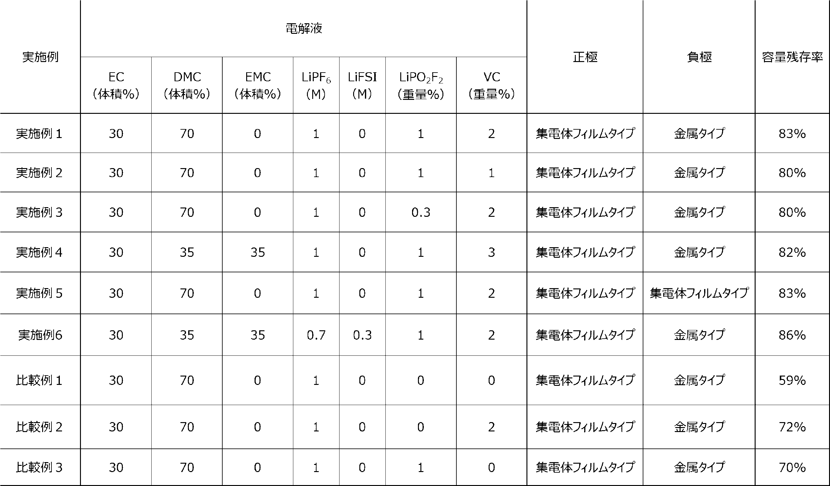
3.評価結果
表1から、正極集電体32と正極活物質層34とを有する正極30と、負極集電体12を有する負極10と、電解液と、セパレータ20とを有し、上記正極集電体32及び/又は上記負極集電体12が、ポリエチレンテレフタラートを含む樹脂層と、当該樹脂層の両面に設けられた金属層とを備える集電体フィルムを有し、上記正極活物質層34が、一般式:LizNixCoyM1-x-yO2+α(ただし、0.5≦x≦1.0、0≦y≦0.35、0.9≦z≦1.3、-0.2≦α≦0.15、Mは、Mn、Al、V、Mg、Mo、Nb、Ti、Zr、Fe、Cu、Cr、Zn、F、及びBからなる群より選ばれる1種以上の元素である。)で表される化合物を1種以上含み、上記電解液が、鎖状カーボネート及び/又は鎖状エーテル、ビニレンカーボネート、並びにジフルオロリン酸リチウムを含む、リチウム2次電池での実施例1~6が、そうでないリチウム2次電池での比較例と比較して、充電状態のリチウム2次電池を高温下で保存した場合にも、優れた容量残存率を示すことがわかる。
3. Evaluation Results From Table 1, a positive electrode 30 having a positive electrode collector 32 and a positive electrode active material layer 34, a negative electrode 10 having a negative electrode collector 12, an electrolyte, and a separator 20 are included, and the positive electrode collector 32 and/or the negative electrode collector 12 have a collector film including a resin layer containing polyethylene terephthalate and metal layers provided on both sides of the resin layer, and the positive electrode active material layer 34 has a structure represented by the general formula: Li z Ni x Co y M 1-x-y O 2 + α (wherein 0.5≦x≦1.0, 0≦y≦0.35, 0.9≦z≦1.3, −0.2≦α≦0.15, and M is one or more elements selected from the group consisting of Mn, Al, V, Mg, Mo, Nb, Ti, Zr, Fe, Cu, Cr, Zn, F, and B), and the electrolyte solution contains a chain carbonate and/or a chain ether, vinylene carbonate, and lithium difluorophosphate, and it is clear that Examples 1 to 6, which are lithium secondary batteries, show excellent capacity residual rates even when the lithium secondary batteries are stored in a charged state at high temperatures, as compared with Comparative Example 1, which is a lithium secondary battery that does not do so.
本発明に係るリチウム2次電池は、高温下で保存した場合にも、優れた容量残存率を示すため、様々な用途に用いられる蓄電デバイスとして、産業上の利用可能性を有する。 The lithium secondary battery of the present invention has excellent capacity retention even when stored at high temperatures, and therefore has industrial applicability as an electricity storage device for a variety of applications.
100,100A,100B…リチウム2次電池、10,10B,10C…負極、12…負極集電体、120…樹脂層、122…金属層、14…負極活物質層、20…セパレータ、30,30B…正極、32…正極集電体、320…樹脂層、322…金属層、34…正極活物質層 100, 100A, 100B...Lithium secondary battery, 10, 10B, 10C...Anode, 12...Anode current collector, 120...Resin layer, 122...Metal layer, 14...Anode active material layer, 20...Separator, 30, 30B...Cathode, 32...Cathode current collector, 320...Resin layer, 322...Metal layer, 34...Cathode active material layer
Claims (5)
前記正極集電体及び/又は前記負極集電体が、ポリエチレンテレフタラートを含む樹脂層と、当該樹脂層の両面に設けられた金属層とを備える集電体フィルムを有し、
前記正極活物質層が、一般式:LizNixCoyM1-x-yO2+α(ただし、0.5≦x≦1.0、0≦y≦0.35、0.9≦z≦1.3、-0.2≦α≦0.15、Mは、Mn、Al、V、Mg、Mo、Nb、Ti、Zr、Fe、Cu、Cr、Zn、F、及びBからなる群より選ばれる1種以上の元素である。)で表される化合物を1種以上含み、
前記電解液が、鎖状カーボネート及び/又は鎖状エーテル、ビニレンカーボネート、並びにジフルオロリン酸リチウムを含む、
リチウム2次電池。 a positive electrode having a positive electrode current collector and a positive electrode active material layer, a negative electrode having a negative electrode current collector, an electrolyte, and a separator;
the positive electrode current collector and/or the negative electrode current collector has a current collector film including a resin layer containing polyethylene terephthalate and metal layers provided on both sides of the resin layer,
The positive electrode active material layer contains one or more compounds represented by the general formula: Li z Ni x Co y M 1-x-y O 2 + α (wherein 0.5≦x≦1.0, 0≦y≦0.35, 0.9≦z≦1.3, −0.2≦α≦0.15, and M is one or more elements selected from the group consisting of Mn, Al, V, Mg, Mo, Nb, Ti, Zr, Fe, Cu, Cr, Zn, F, and B),
The electrolyte solution contains a chain carbonate and/or a chain ether, vinylene carbonate, and lithium difluorophosphate;
Lithium secondary battery.
請求項1に記載のリチウム2次電池。 The positive electrode active material layer contains one or more compounds represented by the general formula: Li z Ni x Co y M 1-x-y O 2 + α (wherein 0.7≦x≦1.0, 0≦y≦0.35, 0.9≦z≦1.3, −0.2≦α≦0.15, and M is one or more elements selected from the group consisting of Mn, Al, V, Mg, Mo, Nb, Ti, Zr, Fe, Cu, Cr, Zn, F, and B).
2. The lithium secondary battery according to claim 1.
前記鎖状カーボネートが、エチルメチルカーボネート及び/又はジメチルカーボネートを含む、
請求項1に記載のリチウム2次電池。 The electrolyte solution contains the chain carbonate,
The chain carbonate includes ethyl methyl carbonate and/or dimethyl carbonate.
2. The lithium secondary battery according to claim 1.
前記ジフルオロリン酸リチウムの含有量が、前記電解液に含まれる溶媒の総量に対して、0.1質量%以上5.0質量%以下である、
請求項1に記載のリチウム2次電池。 The content of the vinylene carbonate is 0.1% by mass or more and 5.0% by mass or less with respect to the total amount of the solvent contained in the electrolytic solution,
The content of the lithium difluorophosphate is 0.1% by mass or more and 5.0% by mass or less with respect to the total amount of the solvent contained in the electrolyte solution.
2. The lithium secondary battery according to claim 1.
請求項1に記載のリチウム2次電池。 The electrolyte further contains lithium hexafluorophosphate and/or lithium bis(fluorosulfonyl)imide;
2. The lithium secondary battery according to claim 1.
Priority Applications (6)
| Application Number | Priority Date | Filing Date | Title |
|---|---|---|---|
| PCT/JP2023/021245 WO2024252593A1 (en) | 2023-06-07 | 2023-06-07 | Lithium secondary battery |
| JP2025525555A JPWO2024252593A1 (en) | 2023-06-07 | 2023-06-07 | |
| EP23940694.5A EP4726836A1 (en) | 2023-06-07 | 2023-06-07 | Lithium secondary battery |
| KR1020257041682A KR20260010441A (en) | 2023-06-07 | 2023-06-07 | lithium secondary battery |
| CN202380098287.3A CN121127992A (en) | 2023-06-07 | 2023-06-07 | Lithium secondary batteries |
| US19/396,978 US20260081208A1 (en) | 2023-06-07 | 2025-11-21 | Lithium secondary battery |
Applications Claiming Priority (1)
| Application Number | Priority Date | Filing Date | Title |
|---|---|---|---|
| PCT/JP2023/021245 WO2024252593A1 (en) | 2023-06-07 | 2023-06-07 | Lithium secondary battery |
Related Child Applications (1)
| Application Number | Title | Priority Date | Filing Date |
|---|---|---|---|
| US19/396,978 Continuation US20260081208A1 (en) | 2023-06-07 | 2025-11-21 | Lithium secondary battery |
Publications (1)
| Publication Number | Publication Date |
|---|---|
| WO2024252593A1 true WO2024252593A1 (en) | 2024-12-12 |
Family
ID=93795646
Family Applications (1)
| Application Number | Title | Priority Date | Filing Date |
|---|---|---|---|
| PCT/JP2023/021245 Ceased WO2024252593A1 (en) | 2023-06-07 | 2023-06-07 | Lithium secondary battery |
Country Status (6)
| Country | Link |
|---|---|
| US (1) | US20260081208A1 (en) |
| EP (1) | EP4726836A1 (en) |
| JP (1) | JPWO2024252593A1 (en) |
| KR (1) | KR20260010441A (en) |
| CN (1) | CN121127992A (en) |
| WO (1) | WO2024252593A1 (en) |
Citations (9)
| Publication number | Priority date | Publication date | Assignee | Title |
|---|---|---|---|---|
| JPH01102711A (en) | 1987-10-15 | 1989-04-20 | Canon Electron Inc | Thin film magnetic head |
| JPH09283149A (en) * | 1996-04-10 | 1997-10-31 | Japan Storage Battery Co Ltd | Current collector of electrode plate for battery and battery using the current collector |
| JPH1167270A (en) * | 1997-08-21 | 1999-03-09 | Sanyo Electric Co Ltd | Nonaqueous electrolyte secondary battery |
| JP2013016321A (en) | 2011-07-01 | 2013-01-24 | Sharp Corp | Collector and nonaqueous secondary battery |
| CN111211353A (en) * | 2020-01-07 | 2020-05-29 | 天津市捷威动力工业有限公司 | Lithium ion battery electrolyte for high-voltage system |
| WO2021131258A1 (en) * | 2019-12-26 | 2021-07-01 | パナソニック株式会社 | Lithium ion battery |
| CN114122493A (en) * | 2020-08-31 | 2022-03-01 | 深圳新宙邦科技股份有限公司 | Lithium-ion battery non-aqueous electrolyte and lithium-ion battery |
| US20220255120A1 (en) * | 2019-07-31 | 2022-08-11 | Shenzhen Capchem Technology Co., Ltd. | Non-aqueous electrolyte for a lithium ion battery and lithium ion battery comprising the electrolyte |
| CN116207351A (en) * | 2023-05-05 | 2023-06-02 | 宁德时代新能源科技股份有限公司 | Electrolyte, lithium secondary battery and electricity utilization device |
Family Cites Families (2)
| Publication number | Priority date | Publication date | Assignee | Title |
|---|---|---|---|---|
| JPH11102711A (en) | 1997-09-25 | 1999-04-13 | Denso Corp | Lithium ion secondary battery |
| WO2020197981A1 (en) | 2019-03-22 | 2020-10-01 | Soteria Battery Innovation Group Inc. | Battery connections and metallized film components in energy storage devices having internal fuses |
-
2023
- 2023-06-07 CN CN202380098287.3A patent/CN121127992A/en active Pending
- 2023-06-07 JP JP2025525555A patent/JPWO2024252593A1/ja active Pending
- 2023-06-07 KR KR1020257041682A patent/KR20260010441A/en active Pending
- 2023-06-07 WO PCT/JP2023/021245 patent/WO2024252593A1/en not_active Ceased
- 2023-06-07 EP EP23940694.5A patent/EP4726836A1/en active Pending
-
2025
- 2025-11-21 US US19/396,978 patent/US20260081208A1/en active Pending
Patent Citations (9)
| Publication number | Priority date | Publication date | Assignee | Title |
|---|---|---|---|---|
| JPH01102711A (en) | 1987-10-15 | 1989-04-20 | Canon Electron Inc | Thin film magnetic head |
| JPH09283149A (en) * | 1996-04-10 | 1997-10-31 | Japan Storage Battery Co Ltd | Current collector of electrode plate for battery and battery using the current collector |
| JPH1167270A (en) * | 1997-08-21 | 1999-03-09 | Sanyo Electric Co Ltd | Nonaqueous electrolyte secondary battery |
| JP2013016321A (en) | 2011-07-01 | 2013-01-24 | Sharp Corp | Collector and nonaqueous secondary battery |
| US20220255120A1 (en) * | 2019-07-31 | 2022-08-11 | Shenzhen Capchem Technology Co., Ltd. | Non-aqueous electrolyte for a lithium ion battery and lithium ion battery comprising the electrolyte |
| WO2021131258A1 (en) * | 2019-12-26 | 2021-07-01 | パナソニック株式会社 | Lithium ion battery |
| CN111211353A (en) * | 2020-01-07 | 2020-05-29 | 天津市捷威动力工业有限公司 | Lithium ion battery electrolyte for high-voltage system |
| CN114122493A (en) * | 2020-08-31 | 2022-03-01 | 深圳新宙邦科技股份有限公司 | Lithium-ion battery non-aqueous electrolyte and lithium-ion battery |
| CN116207351A (en) * | 2023-05-05 | 2023-06-02 | 宁德时代新能源科技股份有限公司 | Electrolyte, lithium secondary battery and electricity utilization device |
Also Published As
| Publication number | Publication date |
|---|---|
| EP4726836A1 (en) | 2026-04-15 |
| JPWO2024252593A1 (en) | 2024-12-12 |
| KR20260010441A (en) | 2026-01-20 |
| CN121127992A (en) | 2025-12-12 |
| US20260081208A1 (en) | 2026-03-19 |
Similar Documents
| Publication | Publication Date | Title |
|---|---|---|
| US7326493B2 (en) | Lithium electrochemical generator comprising at least a bipolar electrode with conductive aluminium or aluminium alloy substrates | |
| JP7551169B2 (en) | Lithium secondary battery | |
| KR20190033448A (en) | Nonaqueous electrolyte for lithium secondary battery and lithium secondary battery comprising the same | |
| CN112447941B (en) | Nonaqueous electrolyte secondary battery | |
| CN114616709A (en) | Electrolyte additive for secondary battery, nonaqueous electrolyte for lithium secondary battery, and lithium secondary battery comprising same | |
| KR20190012364A (en) | Additive for nonaqueous electrolyte, nonaqueous electrolyte for lithium secondary battery comprising the same, and lithium secondary battery | |
| KR102846661B1 (en) | Electrolyte additives for secondary battery, non-aqueous electrolyte for lithium secondary battery comprising same and secondary battery | |
| CN110582883A (en) | Non-aqueous electrolyte solution for lithium secondary battery and lithium secondary battery containing the same | |
| JP4582684B2 (en) | Non-aqueous secondary battery | |
| US20230028203A1 (en) | Production method for solid-state battery, and solid-state battery | |
| WO2025126407A1 (en) | Lithium secondary battery and method for manufacturing lithium secondary battery | |
| US20260081208A1 (en) | Lithium secondary battery | |
| US20260074192A1 (en) | Positive electrode for lithium secondary battery, and lithium secondary battery | |
| JP7546999B1 (en) | Lithium secondary battery and method of manufacturing the same | |
| KR102881373B1 (en) | lithium secondary battery | |
| JP2006228602A (en) | battery | |
| JP7804089B2 (en) | Electrolyte additive for secondary battery, non-aqueous electrolyte for lithium secondary battery containing the same, and lithium secondary battery | |
| KR102580309B1 (en) | Electrolyte additives for secondary battery, non-aqueous electrolyte for secondary battery comprising same and secondary battery | |
| JP7587888B2 (en) | Lithium secondary battery, its use, and manufacturing method | |
| WO2025126484A1 (en) | Lithium secondary battery | |
| WO2025141819A1 (en) | Lithium secondary battery | |
| WO2025057309A1 (en) | Electrolyte for lithium secondary battery and lithium secondary battery | |
| WO2025141848A1 (en) | Lithium secondary battery | |
| WO2025057310A1 (en) | Electrolyte for lithium secondary battery and lithium secondary battery | |
| JP2026509667A (en) | Electrolyte additive, electrolyte for lithium secondary battery containing the same, and lithium secondary battery |
Legal Events
| Date | Code | Title | Description |
|---|---|---|---|
| 121 | Ep: the epo has been informed by wipo that ep was designated in this application |
Ref document number: 23940694 Country of ref document: EP Kind code of ref document: A1 |
|
| ENP | Entry into the national phase |
Ref document number: 2025525555 Country of ref document: JP Kind code of ref document: A |
|
| WWE | Wipo information: entry into national phase |
Ref document number: 2025525555 Country of ref document: JP |
|
| WWE | Wipo information: entry into national phase |
Ref document number: 202517119127 Country of ref document: IN |
|
| WWE | Wipo information: entry into national phase |
Ref document number: 1020257041682 Country of ref document: KR |
|
| WWP | Wipo information: published in national office |
Ref document number: 202517119127 Country of ref document: IN |
|
| WWE | Wipo information: entry into national phase |
Ref document number: 2023940694 Country of ref document: EP |
|
| NENP | Non-entry into the national phase |
Ref country code: DE |
|
| ENP | Entry into the national phase |
Ref document number: 2023940694 Country of ref document: EP Effective date: 20260107 |
|
| ENP | Entry into the national phase |
Ref document number: 2023940694 Country of ref document: EP Effective date: 20260107 |
|
| WWP | Wipo information: published in national office |
Ref document number: 1020257041682 Country of ref document: KR |
|
| ENP | Entry into the national phase |
Ref document number: 2023940694 Country of ref document: EP Effective date: 20260107 |
|
| ENP | Entry into the national phase |
Ref document number: 2023940694 Country of ref document: EP Effective date: 20260107 |
|
| ENP | Entry into the national phase |
Ref document number: 2023940694 Country of ref document: EP Effective date: 20260107 |
|
| WWP | Wipo information: published in national office |
Ref document number: 2023940694 Country of ref document: EP |