WO2024252612A1 - 制御部、移動体、移動ロボット装置、制御方法及び記憶媒体 - Google Patents
制御部、移動体、移動ロボット装置、制御方法及び記憶媒体 Download PDFInfo
- Publication number
- WO2024252612A1 WO2024252612A1 PCT/JP2023/021333 JP2023021333W WO2024252612A1 WO 2024252612 A1 WO2024252612 A1 WO 2024252612A1 JP 2023021333 W JP2023021333 W JP 2023021333W WO 2024252612 A1 WO2024252612 A1 WO 2024252612A1
- Authority
- WO
- WIPO (PCT)
- Prior art keywords
- arm
- moving
- unit
- arm unit
- control unit
- Prior art date
- Legal status (The legal status is an assumption and is not a legal conclusion. Google has not performed a legal analysis and makes no representation as to the accuracy of the status listed.)
- Ceased
Links
Images


Classifications
-
- B—PERFORMING OPERATIONS; TRANSPORTING
- B25—HAND TOOLS; PORTABLE POWER-DRIVEN TOOLS; MANIPULATORS
- B25J—MANIPULATORS; CHAMBERS PROVIDED WITH MANIPULATION DEVICES
- B25J13/00—Controls for manipulators
-
- B—PERFORMING OPERATIONS; TRANSPORTING
- B25—HAND TOOLS; PORTABLE POWER-DRIVEN TOOLS; MANIPULATORS
- B25J—MANIPULATORS; CHAMBERS PROVIDED WITH MANIPULATION DEVICES
- B25J5/00—Manipulators mounted on wheels or on carriages
Definitions
- the present invention relates to a control unit, a mobile body, a mobile robot device, a control method, and a storage medium.
- Patent Document 1 Technology relating to an automatic transport device equipped with a robot arm has been disclosed (see, for example, Patent Document 1).
- One embodiment of the present invention is a control unit that controls a mobile robot device that includes a mobile body and an arm unit attached to the mobile body, and controls the mobile body to move in response to a reaction force generated by a driving force of the arm unit.
- One embodiment of the present invention is a control unit that controls a mobile robot device that includes a mobile body and an arm unit attached to the mobile body, and controls the mobile body to move in a direction opposite to the movement direction of the arm unit so as to cancel out a reaction force generated by the driving force of the arm unit.
- One embodiment of the present invention is a control unit that controls a mobile robot device that includes a mobile body and an arm unit attached to the mobile body, and controls the mobile body to move freely in response to a reaction force generated by the driving force of the arm unit.
- One embodiment of the present invention is a moving object equipped with the above-mentioned control unit.
- One embodiment of the present invention is a mobile robot device that includes the above-mentioned control unit, mobile body, and arm unit.
- One embodiment of the present invention is a control method for controlling a mobile robot device that includes a mobile body and an arm unit attached to the mobile body, and controls the mobile body to move in response to a reaction force generated by a driving force of the arm unit.
- One embodiment of the present invention is a control method for controlling a mobile robot device that includes a mobile body and an arm unit attached to the mobile body, and the control method causes the mobile body to move freely in response to a reaction force generated by a driving force of the arm unit.
- One embodiment of the present invention is a control method for controlling a mobile robot device that includes a mobile body and an arm section attached to the mobile body, and the control method moves the mobile body in a direction opposite to the direction of movement of the arm section so as to cancel out a reaction force generated by the driving force of the arm section.
- One embodiment of the present invention is a control method for controlling a mobile robot device having a mobile body and an arm section attached to the mobile body, the control method being a computer-readable storage medium that stores a program for controlling the mobile body so that it moves in response to a reaction force generated by the driving force of the arm section.
- One embodiment of the present invention is a control method for controlling a mobile robot device having a mobile body and an arm section attached to the mobile body, and is a computer-readable storage medium that stores a program for causing the mobile body to move freely in response to a reaction force generated by the driving force of the arm section.
- One embodiment of the present invention is a control method for controlling a mobile robot device having a mobile body and an arm section attached to the mobile body, the control method being a computer-readable storage medium that stores a program for moving the mobile body in a direction opposite to the direction of movement of the arm section so as to counteract a reaction force generated by a driving force of the arm section.
- FIG. 2 is a diagram showing an example of a side view of the mobile robot device according to the embodiment.
- FIG. 2 is a diagram showing an example of a top view of the mobile robot device according to the embodiment.
- FIG. 2 is a diagram illustrating an example of a wheel portion of the embodiment.
- FIG. 2 is a diagram illustrating an example of a functional configuration of a control device according to an embodiment.
- FIG. 2 is a diagram illustrating an example of an outline of control by a moving object control unit according to an embodiment.
- FIG. 11 is a diagram illustrating an example of an operation of a moving object control unit according to the embodiment.
- FIG. 2 is a diagram illustrating an example of an outline of control by a moving object control unit according to an embodiment.
- the mobile robot device 30 is, for example, an AGV (Automatic Guided Vehicle), which is a device that transports objects under computer control.
- AGV Automatic Guided Vehicle
- FIG. 1 is a diagram showing an example of a side view of a mobile robot device 30 according to the present embodiment.
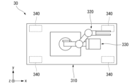
- FIG. 2 is a diagram showing an example of a top view of the mobile robot device 30 according to the present embodiment.
- the mobile robot device 30 includes a moving body 310 , an arm unit 320 , a wheel unit 340 , and a position detection unit 350 .
- the mobile body 310 is a base portion on which each part of the mobile robot device 30 is placed, and is movable in a predetermined direction or any direction by means of wheels 340 .
- the wheel unit 340 is provided on the bottom surface of the moving body 310 and moves the moving body 310.
- the wheel unit 340 can be configured in various shapes.
- the wheel unit 340 is provided at each of the four corners of the bottom surface of the moving body 310, and each wheel is a drive wheel with a variable steering angle.
- the steering angle, rotational speed, rotational force, etc. of the wheel unit 340 are controlled by the control device 1 described later. It is sufficient that one of the multiple wheel units 340 is a driving wheel, and the others may be driven wheels without driving force.
- the mobile robot device 30 is a device that moves on a floor surface, the wheel unit 340 may be guided by rails laid on the floor surface. If the mobile robot device 30 is a device that moves while suspended from a ceiling surface, the wheel unit 340 may be guided by rails installed on the ceiling surface.
- the wheel unit 340 does not need to have a variable steering angle.
- An example of a wheel portion 340 is shown in FIG.
- the arm unit 320 grasps and moves (or processes) an object using an end effector attached to the hand.
- the arm unit 320 is composed of joints and links that connect the joints to each other.
- the arm unit 320 changes the position and posture of the hand by displacing the links due to rotation around the rotation axis of the joint.
- the arm unit 320 is a robot arm with multiple degrees of freedom that is equipped with multiple joints, and is mounted on the moving body 310.
- the arm unit 320 is equipped with a rotary encoder (not shown) for each joint that detects the rotation angle of the joint. Arm unit 320 is displaced relative to mobile body 310, which is the base.
- coordinates expressing the space in which mobile robot device 30 moves by wheel unit 340 are also referred to as global coordinates.
- Coordinates expressing the space in which arm unit 320 moves relative to mobile body 310, which is the base, are also referred to as local coordinates.
- the mobile robot device 30 may also include a counterweight 330.
- the counterweight 330 reduces changes in the center of gravity of the mobile robot device 30 caused by displacement of the arm unit 320 in the local coordinate system.
- the position and orientation of the counterweight 330 may be controlled by an actuator (not shown) in response to the displacement of the arm unit 320 in the local coordinate system.
- the position detection unit 350 detects the position of the moving body 310.
- the position detection unit 350 includes a rotary encoder (not shown) that detects the number of rotations of the wheel of the wheel unit 340, and a rotary encoder (not shown) that detects the steering angle of the wheel unit 340.
- the position detection unit 350 detects the position of the moving body 310 in the global coordinate system by calculating the direction and distance of movement of the moving body 310 based on the results detected by the rotary encoder.
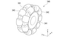
- FIG. 3 is a diagram showing an example of the wheel unit 340 of this embodiment.
- the wheel unit 340 may be configured such that multiple secondary wheels 342 are arranged on the circumference of the wheel 341.
- the secondary wheel 342 has a secondary rotation axis in a direction different from the rotation axis of the wheel 341, and rotates freely around the secondary rotation axis.
- the wheel unit 340 can move the moving body 310 in multiple directions (e.g., the x-axis direction and the y-axis direction) without changing the steering angle by the rotation of the wheel 341 around the rotation axis and the free rotation of the secondary wheel 342 around the secondary rotation axis.
- FIG. 4 is a diagram illustrating an example of a functional configuration of the control device 1 according to the present embodiment.
- the control device 1 controls the behavior of the mobile robot device 30 and each of its components.
- the control device 1 is a device equipped with a calculation function using a microcomputer or the like, and includes a mobile body control unit 10 and an arm control unit 20 as its functional units.
- the mobile body control unit 10 and the arm control unit 20 may be realized as a single device, or may be realized as separate devices.
- the control device 1 may be a computer device mounted on the mobile robot device 30, or may be a computer device not mounted on the mobile robot device 30.
- the control device 1 may be capable of communicating with a device outside the mobile robot device 30 by wired communication or wireless communication.
- the wireless communication may be a method using radio waves such as a wireless LAN (Local Area Network), a public switched telephone network, or microwave communication, or may be a method using light such as laser communication or infrared communication.
- the moving body control unit 10 includes a target position acquisition unit 110 and a position control unit 120 as its functional units.
- Information indicating the target position of the moving body 310 is provided to the moving body control unit 10 from a higher-level device (not shown).
- the target position of the moving body 310 is a position where the moving body 310 should be located so as to be an optimal position when the arm unit 320 operates.
- the information indicating the target position of the moving body 310 is also referred to as moving body target position information.
- the target position acquisition unit 110 acquires moving object target position information from a higher-level device and outputs the acquired moving object target position information to the position control unit 120.
- the position control unit 120 performs feedback control (e.g., position servo control) so that the moving body 310 is positioned at the target position indicated by the moving body target position information.
- feedback control is a control that compares the position of the moving body 310 with the target position and performs a correction operation to match them, and is also called closed-loop control.
- the position control unit 120 feedback controls the position of the moving body 310 based on the moving body target position information acquired by the target position acquisition unit 110 and the position of the moving body 310 detected by the position detection unit 350.
- the position control of the moving body 310 performed by the position control unit 120 is also referred to as positioning control.
- the servo stiffness of the position control of the moving body 310 performed by the position control unit 120 is also referred to as positioning force.
- position control refers to control in which the target value of the servo mechanism is a position or an angle.
- the servo stiffness is the ratio between an external force and a position deviation when position control is performed by a servo mechanism.
- the arm control unit 20 includes an arm target position acquisition unit 210 and an arm drive control unit 220 as its functional units.
- Information indicating a position for the hand (e.g., an end effector) of the arm unit 320 to process an object (e.g., a pallet) is provided to the arm control unit 20 from a higher-level device (not shown).
- information indicating a position for the hand of the arm unit 320 to process an object is also referred to as arm target position information.
- the target position of the hand of the arm unit 320 indicated by the arm target position information is also referred to as arm target position.
- the arm target position acquisition unit 210 acquires arm target position information from a higher-level device and outputs the acquired arm target position information to the arm drive control unit 220.
- the arm drive control unit 220 performs feedback control (e.g., position servo control) to match the position of the hand of the arm unit 320 with the target position indicated by the arm target position information. More specifically, the arm drive control unit 220 feedback controls the position and attitude of the arm unit 320 based on the arm target position information acquired by the arm target position acquisition unit 210 and the rotation angle of each joint output from a rotary encoder of each joint of the arm unit 320. In the following description, controlling the position and controlling the attitude of the arm unit 320 will be collectively referred to as simply "controlling the position.”
- feedback control e.g., position servo control
- the positioning force reduction control of the moving body 310 by the moving body control unit 10 will be described.
- the driving reaction force is a reaction force to the driving force of the arm section 320.
- the moving body control section 10 positions the moving body 310 with a predetermined servo stiffness, if the moving body 310 is affected by the driving reaction force of the arm section 320, vibrations due to servo stiffness may occur in the moving body 310.
- the arm section 320 also vibrates, which may result in a decrease in the positioning accuracy of the end effector of the arm section 320.
- the magnitude of the vibration of the moving body 310 caused by the driving reaction force of the arm portion 320 depends on the magnitude of the servo stiffness (positioning force) of the moving body 310 .
- the moving body control unit 10 of this embodiment reduces the servo stiffness (positioning force) of the moving body 310 when the arm unit 320 is driven, thereby reducing the vibration of the moving body 310 caused by the driving reaction force of the arm unit 320.
- the control that reduces the servo stiffness (positioning force) of the moving body 310 is also referred to as positioning force reduction control.
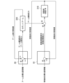
- FIG. 5 is a diagram showing an example of an outline of control by the moving object control unit 10 of this embodiment.
- the moving object control unit 10 performs feedback control of the position of the moving object 310 based on moving object target position information provided from a higher-level device (not shown) and the amount of movement of the moving object 310.
- the amount of movement is the difference between the target position indicated by the moving object target position information and the position of the moving object 310.
- the moving object control unit 10 acquires the moving direction and moving distance of the moving object 310 detected by the position detection unit 350.
- the moving object control unit 10 calculates, as the amount of movement, the relative position of the moving object 310 when the target position indicated by the moving object target position information is set as the origin.
- the arm control unit 20 feedback controls the position of the arm unit 320 based on arm target position information provided by a higher-level device (not shown) and the amount of movement of the arm unit 320 .
- the mobile body control unit 10 performs feedback control of the position of the mobile body 310.
- the mobile body control unit 10 outputs the magnitude of the positioning force in the feedback control to the mobile body 310 as a mobile body drive command.
- the mobile body drive command includes a "normal mobile body drive command” that commands a positioning force of normal magnitude, and a “mobile body drive command with reduced positioning force” that commands a positioning force of reduced magnitude than normal.
- the normal magnitude of positioning force is, for example, a positioning force that does not cause the mobile body 310 to move in the global coordinate system due to the drive reaction force of the arm unit 320 when the arm unit 320 is displaced in the local coordinate system.
- the moving body control unit 10 outputs a moving body drive command with a reduced positioning force to the moving body 310.
- the moving body 310 operates the wheel unit 340 based on the moving body drive command output by the moving body control unit 10.
- the moving body 310 that receives the moving body drive command with the reduced positioning force has a weak positioning force against the driving reaction force of the arm unit 320. Therefore, when the arm unit 320 is displaced in the local coordinate system, the moving body 310 receives the driving reaction force of the arm unit 320 and moves from the target position in the global coordinate system.
- the amount of movement of the moving body 310 in the global coordinate system corresponds to the mass M of the moving body 310.
- the arm control unit 20 of this embodiment obtains the amount of movement of the moving body 310 from the position detection unit 350 of the moving body 310, and controls the position of the arm unit 320 by moving the arm unit 320 in the local coordinates by the amount of movement of the moving body 310.
- the control device 1 of this embodiment is capable of switching between normal positioning control in which the positioning force is not reduced and positioning force reduced control in which the positioning force is reduced to perform positioning control of the moving body 310.
- the control mode in which normal positioning control in which the positioning force is not reduced is also referred to as a first control state
- the control mode in which positioning force reduced control is also referred to as a second control state.
- the operation of the moving object control unit 10 capable of switching between the first control state and the second control state will be described with reference to FIG.
- FIG. 6 is a diagram showing an example of the operation of the moving object control unit 10 of this embodiment.
- Step S10 The moving object control unit 10 acquires moving object target position information from a higher-level device.
- Step S20 The moving object control unit 10 determines the control mode.
- the control mode is given to the moving body control unit 10 by, for example, a higher-level device (not shown).
- the higher-level device sets the first control state (i.e., a positioning control mode with a normal positioning force) when not driving the arm unit 320.
- the higher-level device sets the second control state (i.e., a positioning control mode with a reduced positioning force) when driving the arm unit 320. If the moving object control unit 10 determines that the control mode is the first control state, the process proceeds to step S30. If the moving object control unit 10 determines that the control mode is the second control state, the process proceeds to step S40.
- Step S30 First control state
- the moving body control unit 10 performs positioning control of the moving body 310 using a normal positioning force, and proceeds to step S50.
- Step S40 Second control state
- the moving body control unit 10 performs positioning control of the moving body 310 using the reduced positioning force, and proceeds to step S50.
- Step S50 The mobile body control unit 10 determines whether to end the positioning control. If the mobile body control unit 10 determines not to end the positioning control (Step S50; NO), the process returns to Step S10 and the positioning control is repeated. If the mobile body control unit 10 determines to end the positioning control (Step S50; YES), the process ends.
- the control device 1 controls a mobile robot device 30.
- the mobile robot device 30 includes a mobile body 310 and an arm unit 320 that is attached to the mobile body 310 and whose position relative to the mobile body 310 changes.
- the control device 1 controls the moving body 310 in a first control state in which a target position of the moving body 310 is controlled using a predetermined first positioning force, and a second control state in which the positioning force is reduced below the first positioning force.
- control device 1 is a control unit that controls a mobile robot device 30 that has a moving body 310 and an arm unit 320 provided on the moving body 310, and controls the moving body 310 to move in response to a reaction force generated by the driving force of the arm unit 320.
- the control device 1 configured in this manner performs positioning force reduction control of the moving body 310, thereby making it possible to reduce vibration of the moving body 310 caused by the movement of the arm unit 320 and the position servo stiffness of the moving body 310. Therefore, the control device 1 configured in this manner can reduce vibration of the hand of the arm unit 320 caused by vibration of the moving body 310.
- control device 1 may be a control unit that controls a mobile robot device 30 that has a moving body 310 and an arm unit 320 provided on the moving body 310, and may control the moving body 310 to move freely in response to a reaction force generated by the driving force of the arm unit 320.
- control device 1 may be a control unit that controls a mobile robot device 30 that has a moving body 310 and an arm unit 320 provided on the moving body 310, and controls the moving body 310 to move in a direction opposite to the movement direction of the arm unit 320 so as to cancel out the reaction force generated by the driving force of the arm unit 320.
- the control device 1 controls the position of the hand of the arm section 320 by moving the arm section 320 in the local coordinates by an amount corresponding to the movement of the movable body 310 in the global coordinates due to the arm drive reaction force. That is, when the control device 1 moves the movable body 310 in the direction opposite to the movement direction of the arm section 320, the control device 1 changes the relative position of the hand of the arm section 320 with respect to the movable body 310 based on the amount of movement of the movable body 310 in the global coordinates.
- the servo stiffness is reduced by the positioning force reduction control of the moving body 310, and the position of the hand of the arm unit 320 is corrected by the amount of the change in the position of the moving body 310, so that the position of the hand of the arm unit 320 can be brought closer to the target position.
- the control device 1 configured in this manner it is possible to reduce vibration of the hand of the arm unit 320 caused by the driving reaction force of the arm unit 320 and the position servo stiffness of the moving body 310 without reducing the accuracy of the position control of the arm unit 320.
- the control device 1 may control the target position of the mobile body 310 using a second positioning force obtained by reducing the positioning force in accordance with the drive state of the arm unit 320.
- the drive state of the arm unit 320 includes the presence or absence of movement of the arm unit 320, the movement speed, the movement amount, the movement direction, the state of change in posture, the change in the center of gravity of the arm unit 320, the change in the center of gravity of the mobile robot device 30 due to the movement of the arm unit 320, and the like.
- the force that moves the movable body 310 in the direction opposite to the movement direction of the arm unit 320 may be determined according to the degree of change in the relative position of the hand of the arm unit 320 with respect to the movable body 310 .
- the control device 1 configured in this manner, the amount of change in the position of the moving body 310 can be controlled with higher precision in accordance with the driving state of the arm portion 320 .
- reducing the positioning force of the movable body 310 also includes reducing the positioning force to zero.
- Reducing the positioning force to zero means bringing the movable body 310 into a state in which it can move freely against a force (i.e., an external force) applied to the movable body 310 from outside the movable body 310. That is, the control device 1 may reduce the positioning force of the movable body 310 to zero in the second control state.
- Reducing the positioning force to zero also includes stopping the target position control of the movable body 310. In this case, the control device 1 may reduce the positioning force by stopping the target position control of the movable body 310 in the second control state. According to the control device 1 configured in this manner, it is possible to reduce vibrations caused by the position servo stiffness of the moving body 310 through simpler control.
- the control device 1a of this embodiment includes a mobile object control unit 10a instead of the mobile object control unit 10 described above.
- This embodiment differs from the above-described first embodiment in that the second positioning force, which is a reduced positioning force, is determined based on the driving force of the arm unit 320 and the mass of the moving body 310.
- the force that moves the moving body 310 in the direction opposite to the moving direction of the arm unit 320 is determined based on the driving force of the arm unit 320 and the mass of the moving body 310.
- the same components as those in the first embodiment described above are denoted by the same reference numerals and the description thereof will be omitted.
- the moving body control unit 10a refers to the driving force of the arm unit 320 output by the arm control unit 20.
- the moving body control unit 10a calculates the second positioning force based on the acceleration of the moving body 310, which is obtained by dividing the driving force of the arm unit 320 by the mass M of the moving body 310.
- the control device 1a configured in this manner, the driving reaction force of the arm unit 320 can be cancelled out by the movement of the moving body 310. Therefore, according to the control device 1a, it is possible to reduce vibrations of the hand of the arm unit 320 caused by the position servo stiffness of the moving body 310 with high precision.
- the position detector 350 detects the amount of movement of the moving body 310, but this is not limiting.
- the control device 1 (or the control device 1a; in the following description, these are also collectively referred to as the control device 1) may control the position of the moving body 310 by so-called visual servoing.
- the control device 1 may change the position of the arm section 320 in the local coordinates by calculating the amount of movement of the moving body 310 based on the results of imaging the moving body 310.
- control device 1 may change the position of the arm unit 320 in the local coordinate system by calculating the amount of movement of the moving body 310 based on an image captured by an imaging unit mounted on the mobile robot device 30.
- the control device 1 may calculate the amount of movement of the moving body 310 based on an image of a position detection mark attached to an object to be grasped by the arm unit 320 or an image of a characteristic part of the object. According to the control device 1 configured in this manner, the amount of movement of the moving body 310 due to the displacement of the arm portion 320 can be grasped more precisely, and the accuracy of the position control of the arm portion 320 can be further improved.
- the wheel unit 340 of the moving body 310 may be equipped with a suspension that absorbs displacement in the direction of gravity (for example, in the direction of the z-axis).
- This suspension includes a suspension that can change the rigidity of the displacement in the direction of gravity by an actuator (so-called variable damping force suspension) and a suspension that actively absorbs the displacement in the direction of gravity by an actuator (so-called active suspension).
- the control device 1 may reduce the positioning force of the moving body 310 in the direction of gravity by the actuator when moving the moving body 310 in the direction opposite to the moving direction of the arm unit 320.
- the mobile robot device 30 is equipped with an acceleration sensor (not shown), and the control device 1 may reduce the positioning force of the mobile body 310 in the direction of gravity by calculating the displacement of the mobile body 310 in the direction of gravity due to the driving reaction force of the arm section 320 based on the acceleration in the direction of gravity detected by the acceleration sensor.
- the moving body 310 may also be equipped with wheel units 340 with variable steering angles, or wheel units 340 that can move in multiple directions as shown in FIG. 3.
- the control device 1 may reduce the positioning force in at least two of the movement directions of the wheel units 340.
- the moving body 310 may be configured to be able to rotate around at least an axis in the direction of gravity (e.g., the z-axis) by being driven by the wheel unit 340.
- the control device 1 may reduce the positioning force around the axis in the direction of gravity, which is one of the movement directions of the wheel unit 340.
- the movement direction of the moving body 310 may be limited to one direction along the rails.
- the control device 1 may be configured to reduce the positioning force in one direction determined as the movement direction of the moving body 310 when moving the moving body 310 in the direction opposite to the movement direction of the arm unit 320.
- the mobile robot device 30 has been described as a single-arm robot, but this is not limited to the above.
- the mobile robot device 30 may have multiple arm units 320.
- the mobile robot device 30 may be a dual-arm robot having two arm units 320.
- the mobile body 310 has multiple arm units 320.
- the control device 1 may be configured to reduce the change in the center of gravity caused by the displacement of some of the multiple arm units 320 by the displacement of the other arm units 320 when moving the mobile body 310 in the direction opposite to the movement direction of the arm units 320.
- Mobile robot device 30 may also be provided with a counterweight (not shown) that reduces the rotational moment around the rotation axis of arm unit 320 (e.g., around the z-axis).
- the moving body 310 includes a movable part (counterweight) whose relative position with respect to the moving body 310 changes at least around the gravity direction axis.
- the control device 1 may be configured to reduce the moment around the gravity direction axis caused by the displacement of the arm unit 320 by the displacement of the movable part in the second control state.
- This counterweight moves following the change in the position of the center of gravity of the arm unit 320 caused by the displacement of the arm unit 320 based on the control of the control device 1, thereby reducing the moment around the gravity direction axis caused by the displacement of the arm unit 320.
- the counterweight functions as a counterweight for the displacement of the arm unit 320.
- the position of the arm unit 320 can be controlled with higher accuracy. That is, the moving body 310 is provided with a counterweight that reduces the change in the center of gravity caused by the displacement of the arm portion 320 .
- each unit of each device in the above embodiments may be realized by dedicated hardware, or may be realized by a memory and a microprocessor.
- each unit of each device may be configured with a memory and a CPU (Central Processing Unit), and the functions of each unit of each device may be realized by loading a program (instructions) for realizing the function of the unit into the memory and executing the program.
- a program instructions
- a program for implementing the functions of each unit of each device may be recorded on a computer-readable recording medium, and the program recorded on the recording medium may be read into a computer system and executed to perform processing by each unit of the control unit.
- computer system here includes hardware such as the OS and peripheral devices.
- “computer system” utilizes a WWW system, it also includes the home page providing environment (or display environment).
- “computer-readable recording medium” refers to portable media such as flexible disks, optical magnetic disks, ROMs, and CD-ROMs, as well as storage devices such as hard disks built into computer systems.
- “computer-readable recording medium” also includes devices that dynamically store a program for a short period of time, such as communication lines when transmitting a program via a network such as the Internet or a communication line such as a telephone line, and devices that store a program for a certain period of time, such as volatile memory inside a computer system that serves as a server or client in such cases.
- the above-mentioned program may be one that realizes part of the above-mentioned functions, or may be one that can realize the above-mentioned functions in combination with a program already recorded in the computer system.
Landscapes
- Engineering & Computer Science (AREA)
- Robotics (AREA)
- Mechanical Engineering (AREA)
- Control Of Position, Course, Altitude, Or Attitude Of Moving Bodies (AREA)
Abstract
制御部は、移動体と、前記移動体に設けられるアーム部とを備える移動ロボット装置を制御する制御部であって、前記アーム部の駆動力によって生じる反力に伴って前記移動体が移動するように制御を行う。
Description
本発明は、制御部、移動体、移動ロボット装置、制御方法及び記憶媒体に関する。
従来、ロボットアームを備えた自動搬送装置に関する技術が開示されている(例えば、特許文献1を参照)。
本発明の一実施形態は、移動体と、前記移動体に設けられるアーム部とを備える移動ロボット装置を制御する制御部であって、前記アーム部の駆動力によって生じる反力に伴って前記移動体が移動するように制御を行う制御部である。
本発明の一実施形態は、移動体と、前記移動体に設けられるアーム部とを備える移動ロボット装置を制御する制御部であって、前記アーム部の駆動力によって生じる反力を打ち消すように前記移動体を前記アーム部の移動方向と逆方向に移動させるように制御を行う制御部である。
本発明の一実施形態は、移動体と、前記移動体に設けられるアーム部とを備える移動ロボット装置を制御する制御部であって、前記アーム部の駆動力によって生じる反力に伴って前記移動体を自由移動させるように制御を行う制御部である。
本発明の一実施形態は、上述の制御部を備える移動体である。
本発明の一実施形態は、上述の制御部と移動体とアーム部とを備える移動ロボット装置である。
本発明の一実施形態は、移動体と、前記移動体に設けられるアーム部とを備える移動ロボット装置を制御する制御方法であって、前記アーム部の駆動力によって生じる反力に伴って前記移動体が移動するように制御を行う制御方法である。
本発明の一実施形態は、移動体と、前記移動体に設けられるアーム部とを備える移動ロボット装置を制御する制御方法であって、前記アーム部の駆動力によって生じる反力に伴って前記移動体を自由移動させる制御方法である。
本発明の一実施形態は、移動体と、前記移動体に設けられるアーム部とを備える移動ロボット装置を制御する制御方法であって、前記アーム部の駆動力によって生じる反力を打ち消すように前記移動体を前記アーム部の移動方向と逆方向に移動させる制御方法である。
本発明の一実施形態は、移動体と、前記移動体に設けられるアーム部とを備える移動ロボット装置を制御する制御方法であって、前記アーム部の駆動力によって生じる反力に伴って前記移動体が移動するように制御を行うようにさせるプログラムを記憶しているコンピュータ読み取り可能な記憶媒体である。
本発明の一実施形態は、移動体と、前記移動体に設けられるアーム部とを備える移動ロボット装置を制御する制御方法であって、前記アーム部の駆動力によって生じる反力に伴って前記移動体を自由移動させるようにさせるプログラムを記憶しているコンピュータ読み取り可能な記憶媒体である。
本発明の一実施形態は、移動体と、前記移動体に設けられるアーム部とを備える移動ロボット装置を制御する制御方法であって、前記アーム部の駆動力によって生じる反力を打ち消すように前記移動体を前記アーム部の移動方向と逆方向に移動させるようにさせるプログラムを記憶しているコンピュータ読み取り可能な記憶媒体である。
[第1の実施形態]
以下、図面を参照して、実施形態を説明する。
なお、以下の説明において必要な場合には、x軸、y軸およびz軸からなる三次元直交座標を用いて説明する。x軸及びy軸を含む平面は、移動ロボット装置30が移動する平面を表す。z軸は、移動ロボット装置30の鉛直方向を表す。
移動ロボット装置30は、例えばAGV(Automatic Guided Vehicle;無人搬送車)であり、コンピュータ制御によって物体を搬送する装置である。移動ロボット装置30の具体的な構成について、図1および図2を参照して説明する。
以下、図面を参照して、実施形態を説明する。
なお、以下の説明において必要な場合には、x軸、y軸およびz軸からなる三次元直交座標を用いて説明する。x軸及びy軸を含む平面は、移動ロボット装置30が移動する平面を表す。z軸は、移動ロボット装置30の鉛直方向を表す。
移動ロボット装置30は、例えばAGV(Automatic Guided Vehicle;無人搬送車)であり、コンピュータ制御によって物体を搬送する装置である。移動ロボット装置30の具体的な構成について、図1および図2を参照して説明する。
図1は、本実施形態の移動ロボット装置30の側面視の一例を示す図である。
図2は、本実施形態の移動ロボット装置30の上面視の一例を示す図である。
図1および図2に示すように、移動ロボット装置30は、移動体310と、アーム部320と、車輪部340と、位置検出部350とを備えている。
移動体310は、移動ロボット装置30が備える各部を載置する台座部分であり、車輪部340によって所定の方向、または任意の方向に移動可能である。
車輪部340は、移動体310の底面に備えられており、移動体310を移動させる。車輪部340は、種々の形状に構成することができる。一例として、車輪部340は、移動体310の底面の四隅にそれぞれ備えられている、いずれも舵角可変の駆動輪である。車輪部340は、後述する制御装置1によって舵角、回転速度、回転力などが制御される。
なお、複数ある車輪部340のうち、いずれかが駆動輪であればよく、他は駆動力のない従動輪であってもよい。また、移動ロボット装置30が床面上を移動する装置である場合には、車輪部340は、当該床面に敷かれたレールによって案内されるものであってもよい。また、移動ロボット装置30が天井面から懸垂されて移動する装置である場合には、車輪部340は、当該天井面に設置されたレールによって案内されるものであってもよい。車輪部340は、舵角可変でなくてもよい。
車輪部340の一例を図3に示す。
アーム部320は、手先につけるエンドエフェクタによって物を掴んで移動させる(または、加工する)ものである。アーム部320は、関節(ジョイント)と、関節どうしを接続するリンクとによって構成される。アーム部320は、関節の回転軸まわりの回転によってリンクが変位することにより、手先の位置および姿勢を変化させる。アーム部320は、一例として、複数の関節を備える多自由度のロボットアームであり、移動体310に載置される。アーム部320は、関節の回転角度を検出するロータリーエンコーダ(不図示)を関節ごとに備えている。
アーム部320は、台座部分である移動体310に対して相対的に変位する。以下の説明において、移動ロボット装置30が車輪部340によって移動する空間を表現する座標をグローバル座標とも記載する。また、アーム部320が台座部分である移動体310に対して相対的に移動する空間を表現する座標をローカル座標とも記載する。
アーム部320は、台座部分である移動体310に対して相対的に変位する。以下の説明において、移動ロボット装置30が車輪部340によって移動する空間を表現する座標をグローバル座標とも記載する。また、アーム部320が台座部分である移動体310に対して相対的に移動する空間を表現する座標をローカル座標とも記載する。
なお、移動ロボット装置30は、カウンタウエイト330を備えていてもよい。カウンタウエイト330は、アーム部320のローカル座標における変位による移動ロボット装置30の重心の変化を低減する。カウンタウエイト330は、アーム部320のローカル座標における変位に応じて、アクチュエータ(不図示)によって位置や姿勢を制御されてもよい。
位置検出部350は、移動体310の位置を検出する。例えば、車輪部340が舵角可変の駆動輪である場合には、位置検出部350は、車輪部340の車輪の回転数を検出するロータリーエンコーダ(不図示)と、車輪部340の舵角を検出するロータリーエンコーダ(不図示)を備える。位置検出部350は、ロータリーエンコーダが検出した結果に基づいて、移動体310の移動方向および移動距離を算出することにより、移動体310のグローバル座標における位置を検出する。
図3は、本実施形態の車輪部340の一例を示す図である。図3に示すように、車輪部340は、車輪341の円周上に、副車輪342が複数配置されている構成であってもよい。この構成の場合、副車輪342は、車輪341の回転軸とは異なる方向の副回転軸を有し、副回転軸まわりに自由回転する。車輪部340は、車輪341の回転軸周りの回転と、副車輪342の副回転軸まわりの自由回転とによって、舵角を変化させることなく複数の方向(例えば、x軸方向及びy軸方向)に移動体310を移動させることができる。
図4は、本実施形態の制御装置1の機能構成の一例を示す図である。
制御装置1は、移動ロボット装置30およびその各部の挙動を制御する。制御装置1は、マイクロコンピュータなどによる演算機能を備える装置であり、移動体制御部10と、アーム制御部20とを、その機能部として備える。移動体制御部10とアーム制御部20とは、1つの装置として実現されていてもよいし、互いに別の装置として実現されていてもよい。また、制御装置1は、移動ロボット装置30に搭載されているコンピュータ装置であってもよいし、移動ロボット装置30に搭載されていないコンピュータ装置であってもよい。また、制御装置1は、有線通信、または無線通信によって移動ロボット装置30の外部の装置との通信が可能であってもよい。ここで、無線通信は、無線LAN(Local Area Network)、公衆交換電話網、マイクロ波通信などの電波を利用する方式であってもよく、レーザー通信、赤外線通信などの光を利用する方式であってもよい。
制御装置1は、移動ロボット装置30およびその各部の挙動を制御する。制御装置1は、マイクロコンピュータなどによる演算機能を備える装置であり、移動体制御部10と、アーム制御部20とを、その機能部として備える。移動体制御部10とアーム制御部20とは、1つの装置として実現されていてもよいし、互いに別の装置として実現されていてもよい。また、制御装置1は、移動ロボット装置30に搭載されているコンピュータ装置であってもよいし、移動ロボット装置30に搭載されていないコンピュータ装置であってもよい。また、制御装置1は、有線通信、または無線通信によって移動ロボット装置30の外部の装置との通信が可能であってもよい。ここで、無線通信は、無線LAN(Local Area Network)、公衆交換電話網、マイクロ波通信などの電波を利用する方式であってもよく、レーザー通信、赤外線通信などの光を利用する方式であってもよい。
移動体制御部10は、目標位置取得部110と、位置制御部120とを、その機能部として備える。移動体制御部10には、上位装置(不図示)から移動体310の目標位置を示す情報が与えられる。ここで、移動体310の目標位置とは、アーム部320が動作する際に最適な位置となるように、移動体310が定位すべき位置である。以下の説明において、移動体310の目標位置を示す情報を、移動体目標位置情報とも記載する。
目標位置取得部110は、上位装置から移動体目標位置情報を取得する。目標位置取得部110は、取得した移動体目標位置情報を位置制御部120に出力する。
位置制御部120は、移動体目標位置情報が示す目標位置に移動体310が定位するようにフィードバック制御(例えば、位置サーボ制御)を行う。ここで、フィードバック制御とは、移動体310の位置と目標位置とを比較し、それらを一致させるように訂正動作を行う制御であり、閉ループ制御ともいう。より具体的には、位置制御部120は、目標位置取得部110が取得した移動体目標位置情報と、位置検出部350が検出した移動体310の位置とに基づいて、移動体310の位置をフィードバック制御する。
以下の説明において、位置制御部120が行う移動体310の位置制御を、位置決め制御ともいう。また、位置制御部120が行う移動体310の位置制御のサーボ剛性を、位置決め力ともいう。ここで、位置制御とは、サーボ機構の目標値が位置または角度である制御である。また、サーボ剛性とは、サーボ機構によって位置の制御を行う場合の外力と位置偏差の比である。
アーム制御部20は、アーム目標位置取得部210と、アーム駆動制御部220とを、その機能部として備える。アーム制御部20には、上位装置(不図示)からアーム部320の手先(例えば、エンドエフェクタ)が対象物(例えば、パレット等)に対して処理を行うための位置を示す情報が与えられる。以下の説明において、アーム部320の手先が対象物に対して処理を行うための位置を示す情報をアーム目標位置情報ともいう。また、アーム目標位置情報が示す、アーム部320の手先の目標位置のことを、アーム目標位置ともいう。
アーム目標位置取得部210は、上位装置からアーム目標位置情報を取得する。アーム目標位置取得部210は、取得したアーム目標位置情報をアーム駆動制御部220に出力する。
アーム駆動制御部220は、アーム目標位置情報が示す目標位置にアーム部320の手先の位置を一致させるようにフィードバック制御(例えば、位置サーボ制御)を行う。より具体的には、アーム駆動制御部220は、アーム目標位置取得部210が取得したアーム目標位置情報と、アーム部320の各関節のロータリーエンコーダから出力される各関節の回転角度とに基づいて、アーム部320の位置や姿勢をフィードバック制御する。
なお、以下の説明において、アーム部320について、位置制御することと、姿勢を制御することとを総称して、単に「位置制御する」とも記載する。
[位置決め力低減制御]
ここで、移動体制御部10による移動体310の位置決め力低減制御について説明する。
一般に、アーム部320が駆動されると、移動体310は、アーム部320の駆動反力の影響を受ける。ここで、駆動反力とは、アーム部320の駆動力の反力である。移動体制御部10が移動体310を所定のサーボ剛性で位置決めしている場合に、移動体310がアーム部320の駆動反力の影響を受けると、移動体310には、サーボ剛性に起因する振動が発生することがある。移動体310が振動すると、アーム部320も振動するため、アーム部320のエンドフェクタの位置精度が低下してしまうことがある。
このアーム部320の駆動反力による移動体310の振動の大きさは、移動体310のサーボ剛性(位置決め力)の大きさに依っている。
本実施形態の移動体制御部10は、アーム部320が駆動される際に、移動体310のサーボ剛性(位置決め力)を低減することで、アーム部320の駆動反力による移動体310の振動を低減させる。以下の説明において、移動体310のサーボ剛性(位置決め力)を低減させた制御を、位置決め力低減制御ともいう。
図5は、本実施形態の移動体制御部10による制御の概要の一例を示す図である。
移動体制御部10は、上位装置(不図示)から与えられる移動体目標位置情報と、移動体310の移動量とに基づいて、移動体310の位置をフィードバック制御する。ここで、移動量とは、移動体目標位置情報が示す目標位置と、移動体310の位置との差分である。具体的には、移動体制御部10は、位置検出部350が検出する移動体310の移動方向および移動距離を取得する。移動体制御部10は、取得した移動体310の移動方向および移動距離に基づいて、移動体目標位置情報が示す目標位置を原点とした場合の移動体310の相対位置を、移動量として算出する。
アーム制御部20は、上位装置(不図示)から与えられるアーム目標位置情報と、アーム部320の移動量とに基づいて、アーム部320の位置をフィードバック制御する。
上述したように、移動体制御部10は、移動体310の位置をフィードバック制御する。ここで移動体制御部10は、フィードバック制御における位置決め力の大きさを、移動体駆動指令として移動体310に出力する。移動体駆動指令には、通常の大きさの位置決め力を指令する「通常の移動体駆動指令」と、通常よりも低減された大きさの位置決め力を指令する「位置決め力を低減させた移動体駆動指令」とがある。ここで通常の大きさの位置決め力とは、例えば、アーム部320がローカル座標において変位した場合のアーム部320の駆動反力によって、移動体310がグローバル座標において移動しない程度の位置決め力である。
位置決め力低減制御においては、移動体制御部10は、位置決め力を低減させた移動体駆動指令を移動体310に対して出力する。移動体310は、移動体制御部10が出力する移動体駆動指令に基づき、車輪部340を動作させる。
位置決め力を低減させた移動体駆動指令を受けた移動体310は、アーム部320の駆動反力に対する位置決め力が弱い。このため、アーム部320がローカル座標において変位した場合、移動体310は、アーム部320の駆動反力を受けて、グローバル座標における目標位置から移動する。この移動体310のグローバル座標における移動量は、移動体310の質量Mに応じている。
位置決め力低減制御においては、移動体制御部10は、位置決め力を低減させた移動体駆動指令を移動体310に対して出力する。移動体310は、移動体制御部10が出力する移動体駆動指令に基づき、車輪部340を動作させる。
位置決め力を低減させた移動体駆動指令を受けた移動体310は、アーム部320の駆動反力に対する位置決め力が弱い。このため、アーム部320がローカル座標において変位した場合、移動体310は、アーム部320の駆動反力を受けて、グローバル座標における目標位置から移動する。この移動体310のグローバル座標における移動量は、移動体310の質量Mに応じている。
アーム部320の駆動反力を受けて移動体310がグローバル座標において移動すると、移動体310に載置されたアーム部320もグローバル座標において移動する。このため、アーム部320の位置は、移動体310のグローバル座標における移動量の分、アーム部320の手先の位置が目標位置(すなわち、アーム目標位置)からずれる。
そこで、本実施形態のアーム制御部20は、移動体310の位置検出部350から移動体の移動量を取得し、移動体310の移動量の分、アーム部320をローカル座標において移動させることにより、アーム部320を位置制御する。
そこで、本実施形態のアーム制御部20は、移動体310の位置検出部350から移動体の移動量を取得し、移動体310の移動量の分、アーム部320をローカル座標において移動させることにより、アーム部320を位置制御する。
本実施形態の制御装置1は、位置決め力を低減させない通常の位置決め制御と、位置決め力を低減させた位置決め力低減制御とを切り替えて、移動体310の位置決め制御をすることが可能である。以下の説明において、位置決め力を低減させない通常の位置決め制御を行う制御モードのことを第1制御状態とも記載し、位置決め力低減制御を行う制御モードのことを第2制御状態とも記載する。
これら第1制御状態と第2制御状態とを切り替え可能な移動体制御部10の動作について、図6を参照して説明する。
これら第1制御状態と第2制御状態とを切り替え可能な移動体制御部10の動作について、図6を参照して説明する。
[移動体制御部10の動作]
図6は、本実施形態の移動体制御部10の動作の一例を示す図である。
(ステップS10)移動体制御部10は、上位装置から移動体目標位置情報を取得する。
図6は、本実施形態の移動体制御部10の動作の一例を示す図である。
(ステップS10)移動体制御部10は、上位装置から移動体目標位置情報を取得する。
(ステップS20)移動体制御部10は、制御モードを判定する。
制御モードは、例えば、上位装置(不図示)が、移動体制御部10に対して与える。一例として、上位装置は、アーム部320を駆動しない場合には、第1制御状態(つまり、通常の位置決め力による位置決め制御モード)とする。また、上位装置は、アーム部320を駆動する場合には、第2制御状態(つまり、低減された位置決め力による位置決め制御モード)とする。
移動体制御部10は、制御モードが第1制御状態であると判定すると、処理をステップS30に進める。移動体制御部10は、制御モードが第2制御状態であると判定すると、処理をステップS40に進める。
制御モードは、例えば、上位装置(不図示)が、移動体制御部10に対して与える。一例として、上位装置は、アーム部320を駆動しない場合には、第1制御状態(つまり、通常の位置決め力による位置決め制御モード)とする。また、上位装置は、アーム部320を駆動する場合には、第2制御状態(つまり、低減された位置決め力による位置決め制御モード)とする。
移動体制御部10は、制御モードが第1制御状態であると判定すると、処理をステップS30に進める。移動体制御部10は、制御モードが第2制御状態であると判定すると、処理をステップS40に進める。
(ステップS30:第1制御状態)移動体制御部10は、通常の位置決め力による移動体310の位置決め制御を行い、処理をステップS50に進める。
(ステップS40:第2制御状態)移動体制御部10は、低減させた位置決め力による移動体310の位置決め制御を行い、処理をステップS50に進める。
(ステップS40:第2制御状態)移動体制御部10は、低減させた位置決め力による移動体310の位置決め制御を行い、処理をステップS50に進める。
(ステップS50)移動体制御部10は、位置決め制御の終了判定を行う。移動体制御部10は、位置決め制御を終了させないと判定した場合(ステップS50;NO)には、処理をステップS10に戻して、位置決め制御を繰り返す。移動体制御部10は、位置決め制御を終了させる判定した場合(ステップS50;YES)には、処理を終了する。
[第1の実施形態のまとめ]
制御装置1は、移動ロボット装置30を制御する。この移動ロボット装置30は、移動体310と、移動体310に取り付けられ、移動体310との相対位置が変化するアーム部320とを備える。
上述したように、制御装置1は、所定の第1の位置決め力によって移動体310の目標位置制御を行う第1制御状態と、第1の位置決め力よりも位置決め力を低減した第2制御状態とによって移動体310を制御する。
すなわち、制御装置1(制御部)は、移動体310と、移動体310に設けられるアーム部320とを備える移動ロボット装置30を制御する制御部であって、アーム部320の駆動力によって生じる反力に伴って移動体310が移動するように制御を行う。
このように構成された制御装置1によれば、移動体310の位置決め力低減制御を行うことにより、アーム部320の移動と移動体310の位置サーボ剛性とに起因する移動体310の振動を低減することができる。したがって、このように構成された制御装置1によれば、移動体310の振動に起因するアーム部320の手先の振動を低減することができる。
なお、制御装置1(制御部)は、移動体310と、移動体310に設けられるアーム部320とを備える移動ロボット装置30を制御する制御部であって、アーム部320の駆動力によって生じる反力に伴って移動体310を自由移動させるように制御を行うものであってもよい。
また、制御装置1(制御部)は、移動体310と、移動体310に設けられるアーム部320とを備える移動ロボット装置30を制御する制御部であって、アーム部320の駆動力によって生じる反力を打ち消すように移動体310をアーム部320の移動方向と逆方向に移動させるように制御を行うものであってもよい。
また、上述したように、制御装置1は、移動体310がアーム駆動反力によってグローバル座標において移動した分、アーム部320をローカル座標において移動させることにより、アーム部320の手先の位置を位置制御する。すなわち、制御装置1は、移動体310をアーム部320の移動方向と逆方向に移動させる際、移動体310のグローバル座標における移動量に基づいて、アーム部320の手先の移動体310に対する相対位置を変化させる。
このように構成された制御装置1によれば、移動体310の位置決め力低減制御によりサーボ剛性が低下して、移動体310の位置が変化した分、アーム部320の手先の位置を補正するため、アーム部320の手先の位置を目標位置により近づけることができる。すなわち、このように構成された制御装置1によれば、アーム部320の位置制御の精度を低下させることなく、アーム部320の駆動反力と移動体310の位置サーボ剛性に起因するアーム部320の手先の振動を低減することができる。
このように構成された制御装置1によれば、移動体310の位置決め力低減制御によりサーボ剛性が低下して、移動体310の位置が変化した分、アーム部320の手先の位置を補正するため、アーム部320の手先の位置を目標位置により近づけることができる。すなわち、このように構成された制御装置1によれば、アーム部320の位置制御の精度を低下させることなく、アーム部320の駆動反力と移動体310の位置サーボ剛性に起因するアーム部320の手先の振動を低減することができる。
なお、制御装置1は、第2制御状態において、アーム部320の駆動状態に応じて位置決め力を低減させた第2の位置決め力によって移動体310の目標位置制御を行ってもよい。ここで、アーム部320の駆動状態には、アーム部320の移動の有無、移動速度、移動量、移動方向、姿勢の変化の状態、アーム部320の重心の変化、アーム部320の移動による移動ロボット装置30の重心の変化、などが含まれる。
例えば、移動体310をアーム部320の移動方向と逆方向に移動させる力、すなわち第2の位置決め力は、アーム部320の手先の移動体310に対する相対位置の変化の程度に応じて定められていてもよい。
このように構成された制御装置1によれば、アーム部320の駆動状態に応じて、移動体310の位置の変化量を、より高精度に制御することができる。
例えば、移動体310をアーム部320の移動方向と逆方向に移動させる力、すなわち第2の位置決め力は、アーム部320の手先の移動体310に対する相対位置の変化の程度に応じて定められていてもよい。
このように構成された制御装置1によれば、アーム部320の駆動状態に応じて、移動体310の位置の変化量を、より高精度に制御することができる。
[変形例]
ここで、移動体310の位置決め力を低減させることには、位置決め力をゼロにすることも含まれる。ここで、位置決め力をゼロにするとは、移動体310の外部から移動体310に対して加えられた力(すなわち、外力)に対して、移動体310が自由に移動する状態にすることをいう。すなわち、制御装置1は、第2制御状態において、移動体310の位置決め力をゼロに低減させてもよい。また、位置決め力をゼロにすることには、移動体310の目標位置制御を停止することも含まれる。この場合、制御装置1は、第2制御状態において、移動体310の目標位置制御を停止することにより、位置決め力を低減させてもよい。
このように構成された制御装置1によれば、より簡易な制御によって、移動体310の位置サーボ剛性に起因する振動を低減することができる。
[第2の実施形態]
本実施形態の制御装置1aは、上述した移動体制御部10に代えて、移動体制御部10aを備えている。
本実施形態においては、位置決め力を低減させた第2の位置決め力が、アーム部320の駆動力と、移動体310の質量とに基づいて定められている点において、上述した第1の実施形態と異なる。すなわち、移動体310をアーム部320の移動方向と逆方向に移動させる力は、アーム部320の駆動力と、移動体310の質量とに基づいて定められる。
なお、上述した第1の実施形態と同様の構成については、同一の符号を付してその説明を省略する。
本実施形態の制御装置1aは、上述した移動体制御部10に代えて、移動体制御部10aを備えている。
本実施形態においては、位置決め力を低減させた第2の位置決め力が、アーム部320の駆動力と、移動体310の質量とに基づいて定められている点において、上述した第1の実施形態と異なる。すなわち、移動体310をアーム部320の移動方向と逆方向に移動させる力は、アーム部320の駆動力と、移動体310の質量とに基づいて定められる。
なお、上述した第1の実施形態と同様の構成については、同一の符号を付してその説明を省略する。
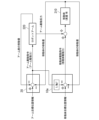
図7は、本実施形態の移動体制御部10aによる制御の概要の一例を示す図である。移動体制御部10aは、位置決め力を低減させた第2の位置決め力を算出する際に、アーム制御部20が出力するアーム部320の駆動力を参照する。移動体制御部10aは、アーム部320の駆動力を移動体310の質量Mで除した、移動体310の加速度に基づいて、第2の位置決め力を算出する。
このように構成された制御装置1aによれば、アーム部320の駆動反力を移動体310の移動によって打ち消すことができる。したがって、制御装置1aによれば、移動体310の位置サーボ剛性に起因するアーム部320の手先の振動をより高精度に低減することができる。
このように構成された制御装置1aによれば、アーム部320の駆動反力を移動体310の移動によって打ち消すことができる。したがって、制御装置1aによれば、移動体310の位置サーボ剛性に起因するアーム部320の手先の振動をより高精度に低減することができる。
[変形例]
上述した各実施形態において、移動体310の移動量を位置検出部350が検出するものとして説明したが、これに限られない。例えば、制御装置1(または制御装置1a。以下の説明においては、これらを総称して制御装置1とも記載する。)は、いわゆるビジュアルサーボによって移動体310の位置を制御してもよい。
すなわち、制御装置1は、移動体310をアーム部320の移動方向と逆方向に移動させる際、移動体310を撮像した結果に基づいて移動体310の移動量を算出することにより、アーム部320のローカル座標における位置を変化させてもよい。
また、制御装置1は、移動ロボット装置30に搭載した撮像部によって撮像された画像に基づいて移動体310の移動量を算出することにより、アーム部320のローカル座標における位置を変化させてもよい。この場合、制御装置1は、アーム部320の把持対象である対象物に付された位置検出用マークの画像や、対象物の特徴部分の画像に基づいて移動体310の移動量を算出してもよい。
このように構成された制御装置1によれば、アーム部320の変位による移動体310の移動量をより精密に把握することができ、アーム部320の位置制御の精度をより高めることができる。
また、移動体310の車輪部340が重力方向(例えば、z軸の方向)の変位を吸収するサスペンションを備えている場合がある。このサスペンションには、重力方向の変位の剛性をアクチュエータによって変化できるもの(いわゆる減衰力可変サスペンション)や、重力方向の変位をアクチュエータによって能動的に吸収するもの(いわゆるアクティブ・サスペンション)などが含まれる。このように、移動体310が、重力方向の変位量を制御するアクチュエータを備えている場合には、制御装置1は、移動体310をアーム部320の移動方向と逆方向に移動させる際、アクチュエータによる移動体310の重力方向の位置決め力を低減させてもよい。
なお、この場合において、移動ロボット装置30は、加速度センサ(不図示)を備えており、制御装置1は、加速度センサが検出した重力方向の加速度に基づいて、アーム部320の駆動反力による移動体310の重力方向の変位を算出することにより、移動体310の重力方向の位置決め力を低減させてもよい。
なお、この場合において、移動ロボット装置30は、加速度センサ(不図示)を備えており、制御装置1は、加速度センサが検出した重力方向の加速度に基づいて、アーム部320の駆動反力による移動体310の重力方向の変位を算出することにより、移動体310の重力方向の位置決め力を低減させてもよい。
また、移動体310が、舵角可変の車輪部340、または図3に示したような複数の方向に移動可能な車輪部340を備えている場合がある。この場合には、制御装置1は、移動体310をアーム部320の移動方向と逆方向に移動させる際、車輪部340による移動方向のうち、少なくとも2方向への位置決め力を低減させてもよい。
また、移動体310が、車輪部340の駆動によって、少なくとも重力方向の軸(例えば、z軸)周りに回転移動できるように構成されている場合がある。この場合には、制御装置1は、移動体310をアーム部320の移動方向と逆方向に移動させる際、車輪部340による移動方向のうち、重力方向軸周り方向の位置決め力を低減させてもよい。
また、車輪部340が床上や天井のレールに案内される構成の場合において、移動体310の移動方向がレールに沿った1方向に制限されている場合がある。この場合、制御装置1は、移動体310をアーム部320の移動方向と逆方向に移動させる際、移動体310の移動方向として定められた1方向への位置決め力を低減させるように構成されていてもよい。
また、上述した各実施形態において移動ロボット装置30が単腕ロボットであるとして説明したがこれに限られない。移動ロボット装置30は複数のアーム部320を備えていてもよい、例えば、移動ロボット装置30は、2つのアーム部320を備える双腕ロボットであってもよい。すなわち、移動体310は、アーム部320を複数備えている。この場合、制御装置1は、移動体310をアーム部320の移動方向と逆方向に移動させる際、複数のアーム部320のうち一部のアーム部320の変位による重心の変化を、他のアーム部320の変位により低減させるように構成されていてもよい。
また、移動ロボット装置30は、アーム部320の回転軸周り(例えば、z軸周り)の回転モーメントを低減させるカウンタウエイト(不図示)を備えていてもよい。
例えば、移動体310は、移動体310との相対位置が少なくとも重力方向軸周りに変化する可動部(カウンタウエイト)を備えている。この場合、制御装置1は、第2制御状態において、アーム部320の変位による重力方向軸周りのモーメントを、可動部の変位により低減させるように構成されていてもよい。このカウンタウエイトは、制御装置1の制御に基づいて、アーム部320の変位によるアーム部320の重心位置の変化に追従して移動することにより、アーム部320の変位による重力方向軸周りのモーメントを低減させる。すなわち、カウンタウエイトがアーム部320の変位に対する釣合い重りとして機能する。このように構成された制御装置1によれば、アーム部320の位置をより高精度に制御することができる。
すなわち、移動体310は、アーム部320の変位による重心の変化を低減する釣合い重り(カウンタウエイト)を備える。
以上、本発明の実施形態を図面を参照して詳述してきたが、具体的な構成はこの実施形態に限られるものではなく、本発明の趣旨を逸脱しない範囲で適宜変更を加えることができる。上述した各実施形態に記載の構成を組み合わせてもよい。
なお、上記の実施形態における各装置が備える各部は、専用のハードウェアにより実現されるものであってもよく、また、メモリおよびマイクロプロセッサにより実現させるものであってもよい。
なお、各装置が備える各部は、メモリおよびCPU(中央演算装置)により構成され、各装置が備える各部の機能を実現するためのプログラム(命令)をメモリにロードして実行することによりその機能を実現させるものであってもよい。
また、各装置が備える各部の機能を実現するためのプログラムをコンピュータ読み取り可能な記録媒体に記録して、この記録媒体に記録されたプログラムをコンピュータシステムに読み込ませ、実行することにより、制御部が備える各部による処理を行ってもよい。なお、ここでいう「コンピュータシステム」とは、OSや周辺機器等のハードウェアを含むものとする。
また、「コンピュータシステム」は、WWWシステムを利用している場合であれば、ホームページ提供環境(あるいは表示環境)も含むものとする。
また、「コンピュータ読み取り可能な記録媒体」とは、フレキシブルディスク、光磁気ディスク、ROM、CD-ROM等の可搬媒体、コンピュータシステムに内蔵されるハードディスク等の記憶装置のことをいう。さらに「コンピュータ読み取り可能な記録媒体」とは、インターネット等のネットワークや電話回線等の通信回線を介してプログラムを送信する場合の通信線のように、短時間の間、動的にプログラムを保持するもの、その場合のサーバやクライアントとなるコンピュータシステム内部の揮発性メモリのように、一定時間プログラムを保持しているものも含むものとする。また上記プログラムは、前述した機能の一部を実現するためのものであってもよく、さらに前述した機能をコンピュータシステムにすでに記録されているプログラムとの組み合わせで実現できるものであってもよい。
また、「コンピュータ読み取り可能な記録媒体」とは、フレキシブルディスク、光磁気ディスク、ROM、CD-ROM等の可搬媒体、コンピュータシステムに内蔵されるハードディスク等の記憶装置のことをいう。さらに「コンピュータ読み取り可能な記録媒体」とは、インターネット等のネットワークや電話回線等の通信回線を介してプログラムを送信する場合の通信線のように、短時間の間、動的にプログラムを保持するもの、その場合のサーバやクライアントとなるコンピュータシステム内部の揮発性メモリのように、一定時間プログラムを保持しているものも含むものとする。また上記プログラムは、前述した機能の一部を実現するためのものであってもよく、さらに前述した機能をコンピュータシステムにすでに記録されているプログラムとの組み合わせで実現できるものであってもよい。
1…制御装置、10…移動体制御部、20…アーム制御部、30…移動ロボット装置、310…移動体、320…アーム部、330…カウンタウエイト、340…車輪部、350…位置検出部
Claims (21)
- 移動体と、前記移動体に設けられるアーム部とを備える移動ロボット装置を制御する制御部であって、
前記アーム部の駆動力によって生じる反力に伴って前記移動体が移動するように制御を行う
制御部。 - 移動体と、前記移動体に設けられるアーム部とを備える移動ロボット装置を制御する制御部であって、
前記アーム部の駆動力によって生じる反力に伴って前記移動体を自由移動させるように制御を行う
制御部。 - 移動体と、前記移動体に設けられるアーム部とを備える移動ロボット装置を制御する制御部であって、
前記アーム部の駆動力によって生じる反力を打ち消すように前記移動体を前記アーム部の移動方向と逆方向に移動させるように制御を行う
制御部。 - 前記移動体を前記アーム部の移動方向と逆方向に移動させる力は、前記アーム部の駆動力と、前記移動体の質量とに基づいて定められる
請求項3の制御部。 - 前記移動体を前記アーム部の移動方向と逆方向に移動させる力は、前記アーム部の相対位置の変化に応じて定められる
請求項3の制御部。 - 前記移動体を前記アーム部の移動方向と逆方向に移動させる際、前記移動体の移動量に基づいて、前記アーム部の相対位置を変化させる
請求項3の制御部。 - 前記移動体を前記アーム部の移動方向と逆方向に移動させる際、前記移動体を撮像した結果に基づいて前記移動体の移動量を算出することにより、前記アーム部を駆動させる
請求項6の制御部。 - 前記移動体は、重力方向の変位量を制御するアクチュエータを備えており、
前記移動体を前記アーム部の移動方向と逆方向に移動させる際、前記アクチュエータによる前記移動体の重力方向の位置決め力を低減させる
請求項3の制御部。 - 前記移動体は、複数の方向に移動可能な車輪部を備えており、
前記移動体を前記アーム部の移動方向と逆方向に移動させる際、前記車輪部による移動方向のうち、少なくとも2方向への位置決め力を低減させる
請求項3の制御部。 - 前記移動体を前記アーム部の移動方向と逆方向に移動させる際、前記車輪部による移動方向のうち、重力方向軸周り方向の位置決め力を低減させる
請求項9の制御部。 - 前記移動体は、前記アーム部を複数備えており、
前記移動体を前記アーム部の移動方向と逆方向に移動させる際、複数の前記アーム部のうち一部の前記アーム部の変位による重心の変化を、他の前記アーム部の変位により低減させる
請求項3の制御部。 - 前記移動体は、前記移動体との相対位置が少なくとも重力方向軸周りに変化する可動部を備えており、
前記移動体を前記アーム部の移動方向と逆方向に移動させる際、前記アーム部の変位による重力方向軸周りのモーメントを、前記可動部の変位により低減させる
請求項3の制御部。 - 請求項1から請求項12のいずれか一項の制御部
を備える移動体。 - 請求項1から請求項12のいずれか一項の制御部と、
前記移動体と、
前記アーム部と、
を備える移動ロボット装置。 - 前記移動体は、前記アーム部の変位による重心の変化を低減する釣合い重りを備える
請求項14の移動ロボット装置。 - 移動体と、前記移動体に設けられるアーム部とを備える移動ロボット装置を制御する制御方法であって、
前記アーム部の駆動力によって生じる反力に伴って前記移動体が移動するように制御を行う
制御方法。 - 移動体と、前記移動体に設けられるアーム部とを備える移動ロボット装置を制御する制御方法であって、
前記アーム部の駆動力によって生じる反力に伴って前記移動体を自由移動させる
制御方法。 - 移動体と、前記移動体に設けられるアーム部とを備える移動ロボット装置を制御する制御方法であって、
前記アーム部の駆動力によって生じる反力を打ち消すように前記移動体を前記アーム部の移動方向と逆方向に移動させる
制御方法。 - 移動体と、前記移動体に設けられるアーム部とを備える移動ロボット装置を制御する制御方法であって、
前記アーム部の駆動力によって生じる反力に伴って前記移動体が移動するように制御を行う
ようにさせるプログラムを記憶しているコンピュータ読み取り可能な記憶媒体。 - 移動体と、前記移動体に設けられるアーム部とを備える移動ロボット装置を制御する制御方法であって、
前記アーム部の駆動力によって生じる反力に伴って前記移動体を自由移動させる
ようにさせるプログラムを記憶しているコンピュータ読み取り可能な記憶媒体。 - 移動体と、前記移動体に設けられるアーム部とを備える移動ロボット装置を制御する制御方法であって、
前記アーム部の駆動力によって生じる反力を打ち消すように前記移動体を前記アーム部の移動方向と逆方向に移動させる
ようにさせるプログラムを記憶しているコンピュータ読み取り可能な記憶媒体。
Priority Applications (1)
| Application Number | Priority Date | Filing Date | Title |
|---|---|---|---|
| PCT/JP2023/021333 WO2024252612A1 (ja) | 2023-06-08 | 2023-06-08 | 制御部、移動体、移動ロボット装置、制御方法及び記憶媒体 |
Applications Claiming Priority (1)
| Application Number | Priority Date | Filing Date | Title |
|---|---|---|---|
| PCT/JP2023/021333 WO2024252612A1 (ja) | 2023-06-08 | 2023-06-08 | 制御部、移動体、移動ロボット装置、制御方法及び記憶媒体 |
Publications (1)
| Publication Number | Publication Date |
|---|---|
| WO2024252612A1 true WO2024252612A1 (ja) | 2024-12-12 |
Family
ID=93795597
Family Applications (1)
| Application Number | Title | Priority Date | Filing Date |
|---|---|---|---|
| PCT/JP2023/021333 Ceased WO2024252612A1 (ja) | 2023-06-08 | 2023-06-08 | 制御部、移動体、移動ロボット装置、制御方法及び記憶媒体 |
Country Status (1)
| Country | Link |
|---|---|
| WO (1) | WO2024252612A1 (ja) |
Citations (10)
| Publication number | Priority date | Publication date | Assignee | Title |
|---|---|---|---|---|
| JPH01289683A (ja) * | 1988-05-12 | 1989-11-21 | Mitsubishi Electric Corp | 人工衛星 |
| JPH02141398A (ja) * | 1988-11-24 | 1990-05-30 | Fujitsu Ltd | 宇宙装置の姿勢保持制御方式 |
| US5214749A (en) * | 1991-06-12 | 1993-05-25 | Massachusetts Institute Of Technology | Dynamic control of a robot with its center of mass decoupled from an end effector by a redundant linkage |
| JP2011173218A (ja) * | 2010-02-25 | 2011-09-08 | Toyota Motor Corp | 搬送装置及びその位置決め方法 |
| WO2013038998A1 (ja) * | 2011-09-13 | 2013-03-21 | 株式会社安川電機 | 自走ロボットおよび自走台車 |
| JP2013094947A (ja) * | 2011-11-04 | 2013-05-20 | Honda Motor Co Ltd | ロボットアーム |
| JP2013193198A (ja) * | 2012-03-23 | 2013-09-30 | National Institute Of Advanced Industrial Science & Technology | 壁面走行用ロボット |
| JP2018008320A (ja) * | 2016-07-11 | 2018-01-18 | 国立大学法人広島大学 | 多関節ロボットアーム及びuav |
| JP2020163482A (ja) * | 2019-03-28 | 2020-10-08 | セイコーエプソン株式会社 | ロボットの制御方法およびロボットシステム |
| JP2020192620A (ja) * | 2019-05-24 | 2020-12-03 | 株式会社デンソーウェーブ | ロボットシステム |
-
2023
- 2023-06-08 WO PCT/JP2023/021333 patent/WO2024252612A1/ja not_active Ceased
Patent Citations (10)
| Publication number | Priority date | Publication date | Assignee | Title |
|---|---|---|---|---|
| JPH01289683A (ja) * | 1988-05-12 | 1989-11-21 | Mitsubishi Electric Corp | 人工衛星 |
| JPH02141398A (ja) * | 1988-11-24 | 1990-05-30 | Fujitsu Ltd | 宇宙装置の姿勢保持制御方式 |
| US5214749A (en) * | 1991-06-12 | 1993-05-25 | Massachusetts Institute Of Technology | Dynamic control of a robot with its center of mass decoupled from an end effector by a redundant linkage |
| JP2011173218A (ja) * | 2010-02-25 | 2011-09-08 | Toyota Motor Corp | 搬送装置及びその位置決め方法 |
| WO2013038998A1 (ja) * | 2011-09-13 | 2013-03-21 | 株式会社安川電機 | 自走ロボットおよび自走台車 |
| JP2013094947A (ja) * | 2011-11-04 | 2013-05-20 | Honda Motor Co Ltd | ロボットアーム |
| JP2013193198A (ja) * | 2012-03-23 | 2013-09-30 | National Institute Of Advanced Industrial Science & Technology | 壁面走行用ロボット |
| JP2018008320A (ja) * | 2016-07-11 | 2018-01-18 | 国立大学法人広島大学 | 多関節ロボットアーム及びuav |
| JP2020163482A (ja) * | 2019-03-28 | 2020-10-08 | セイコーエプソン株式会社 | ロボットの制御方法およびロボットシステム |
| JP2020192620A (ja) * | 2019-05-24 | 2020-12-03 | 株式会社デンソーウェーブ | ロボットシステム |
Similar Documents
| Publication | Publication Date | Title |
|---|---|---|
| US11738456B2 (en) | Palletizing boxes | |
| US9452532B2 (en) | Robot, device and method for controlling robot, and computer-readable non-transitory recording medium | |
| JP4716392B2 (ja) | ペイロードの被安定化プラットホーム装置 | |
| US9889562B1 (en) | Smart kickstand for balancing a mobile robotic arm | |
| JP4490997B2 (ja) | 移動ロボット | |
| JP7143633B2 (ja) | ロボットシステム、制御装置および制御方法 | |
| CN113631324A (zh) | 多主体控制器和机器人 | |
| JP7549340B2 (ja) | ロボット | |
| EP3839464B1 (en) | Multiple degree of freedom force sensor | |
| JP7091733B2 (ja) | 位置推定システム、位置検出方法、およびプログラム | |
| CN111278610A (zh) | 用于运行可移动机器人的方法和系统 | |
| KR102236139B1 (ko) | 이동 로봇의 보행 제어 시스템과 방법 및 이를 위한 컴퓨터 프로그램 | |
| WO2020012710A1 (ja) | マニピュレータ制御装置、マニピュレータ制御方法、及びマニピュレータ制御プログラム | |
| JP5454333B2 (ja) | 移動体装置及び移動制御プログラム | |
| CN117426872A (zh) | 包括支承结构和机器人定位器的系统 | |
| JP7537075B2 (ja) | 移動ロボット | |
| US11519550B2 (en) | Stabilization device and method for stabilizing an attachment component | |
| JP5758777B2 (ja) | ロボット | |
| JP2020146794A (ja) | ロボットシステム、制御装置、および制御方法 | |
| WO2024252612A1 (ja) | 制御部、移動体、移動ロボット装置、制御方法及び記憶媒体 | |
| JP4613539B2 (ja) | ロボットの動作計画方法 | |
| US20210146542A1 (en) | Control method for robot system | |
| JP2020131388A (ja) | ロボットシステム、制御装置、および制御方法 | |
| JP7789148B1 (ja) | 作業ロボット、作業ロボットの制御方法 | |
| KR102863414B1 (ko) | 김블 컨트롤러의 동작 방법, 및 이를 이용하는 장치 및 프로그램 |
Legal Events
| Date | Code | Title | Description |
|---|---|---|---|
| 121 | Ep: the epo has been informed by wipo that ep was designated in this application |
Ref document number: 23940711 Country of ref document: EP Kind code of ref document: A1 |
|
| NENP | Non-entry into the national phase |
Ref country code: DE |