WO2024252641A1 - Station placement design device, station placement design method, and program - Google Patents
Station placement design device, station placement design method, and program Download PDFInfo
- Publication number
- WO2024252641A1 WO2024252641A1 PCT/JP2023/021429 JP2023021429W WO2024252641A1 WO 2024252641 A1 WO2024252641 A1 WO 2024252641A1 JP 2023021429 W JP2023021429 W JP 2023021429W WO 2024252641 A1 WO2024252641 A1 WO 2024252641A1
- Authority
- WO
- WIPO (PCT)
- Prior art keywords
- design
- value
- station
- received power
- result evaluation
- Prior art date
- Legal status (The legal status is an assumption and is not a legal conclusion. Google has not performed a legal analysis and makes no representation as to the accuracy of the status listed.)
- Pending
Links
Images


Classifications
-
- H—ELECTRICITY
- H04—ELECTRIC COMMUNICATION TECHNIQUE
- H04W—WIRELESS COMMUNICATION NETWORKS
- H04W16/00—Network planning, e.g. coverage or traffic planning tools; Network deployment, e.g. resource partitioning or cells structures
- H04W16/18—Network planning tools
-
- H—ELECTRICITY
- H04—ELECTRIC COMMUNICATION TECHNIQUE
- H04W—WIRELESS COMMUNICATION NETWORKS
- H04W24/00—Supervisory, monitoring or testing arrangements
- H04W24/06—Testing, supervising or monitoring using simulated traffic
Definitions
- This disclosure relates to design techniques for installing wireless communication base stations.
- station placement design is carried out to determine the installation location of base stations and the direction of antennas.
- methods such as the ray tracing method (Non-Patent Document 1) are used to perform a simulation evaluation of the coverage area. This method is based on received power, and the design results are evaluated linearly using the obtained received power values.
- the range of transmission speeds that can be obtained when the received power changes is predetermined as the transmission characteristics of the wireless communication method, and when the received power value exceeds a specified upper limit (e.g., -59 dBm), the transmission speed does not increase in proportion to the received power value but reaches a plateau.
- a specified upper limit e.g., -59 dBm
- the transmission speed does not increase in proportion to the received power value but reaches a plateau.
- a specified upper limit e.g., -59 dBm
- the transmission speed does not increase in proportion to the received power value but reaches a plateau.
- a specified lower limit e.g., -82 dBM
- communication is impossible regardless of the received power value because radio waves of sufficient strength for communication do not reach the receiving position (evaluation position).
- conventional station placement design methods sometimes obtained design results with a received power that allows communication, albeit unstable, even when communication is actually impossible.
- the present invention was made in consideration of the above points, and aims to perform station placement design according to the transmission characteristics of a wireless communication system.
- the invention of claim 1 is a station location design device that designs the installation of a wireless communication base station, and has a derivation unit that derives a first design result evaluation value that is a constant value when the value of the received power at the evaluation position during the design is equal to or greater than a first predetermined value.
- the present invention has the effect of enabling station placement design according to the transmission characteristics of a wireless communication system.
- FIG. 1 is an overall configuration diagram of a communication system according to an embodiment.
- FIG. 2 is an electrical hardware configuration diagram of the station design apparatus according to the embodiment.
- FIG. 2 is a diagram illustrating an electrical hardware configuration of a communication terminal according to the embodiment.
- FIG. 2 is a functional configuration diagram of a station design device according to an embodiment.
- FIG. 1 is a conceptual diagram of an area subject to station placement design.
- FIG. 13 is a conceptual diagram illustrating a conversion table.
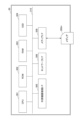
- Fig. 1 is a diagram showing the overall configuration of a communication system according to the embodiment.
- the communication system 10 of the embodiment is constructed by a station placement design device 30 and a communication terminal 50.
- the communication terminal 50 is managed and used by a user.
- the user refers to the output result of the station placement design device 30 and decides on the next action to be taken.
- the station design device 30 and the communication terminal 50 can communicate with each other via a communication network 100 such as the Internet.
- the connection form of the communication network 100 may be either wireless or wired.
- the station placement design device 30 is composed of one or more computers. When the station placement design device 30 is composed of multiple computers, it may be referred to as a "station placement design device” or a "station placement design system.”
- the station placement design device 30 is a device that designs the installation of wireless communication base stations.
- the communication terminal 50 is a computer, and FIG. 1 shows a notebook computer as an example.
- a user operates the communication terminal 50.
- the station design device 30 may perform processing alone, without using the communication terminal 50.
- FIG. 2 is a diagram showing the electrical hardware configuration of the station placement design device.
- the station design device 30 is a computer equipped with a processor such as a CPU (Central Processing Unit) 301, a ROM (Read Only Memory) 302, a RAM (Random Access Memory) 303, an SSD (Solid State Drive) 304, an external device connection I/F (Interface) 305, a network I/F 306, a media I/F 309, and a bus line 310.
- a processor such as a CPU (Central Processing Unit) 301, a ROM (Read Only Memory) 302, a RAM (Random Access Memory) 303, an SSD (Solid State Drive) 304, an external device connection I/F (Interface) 305, a network I/F 306, a media I/F 309, and a bus line 310.
- a processor such as a CPU (Central Processing Unit) 301, a ROM (Read Only Memory) 302, a RAM (Random Access Memory) 303, an SSD (Solid State Drive) 304, an external device connection I/F (
- CPU 301 controls the operation of the entire station design device 30.
- ROM 302 stores programs used to drive CPU 301, such as IPL (Initial Program Loader).
- RAM 303 is used as a work area for CPU 301.
- the SSD 304 reads and writes various data according to the control of the CPU 301. Note that a HDD (Hard Disk Drive) may be used instead of the SSD 304.
- HDD Hard Disk Drive
- the external device connection I/F 305 is an interface for connecting various external devices.
- the external devices include a display, a speaker, a keyboard, a mouse, a USB (Universal Serial Bus) memory, and a printer.
- USB Universal Serial Bus
- the network I/F 306 is an interface for data communication via the communication network 100.
- the media I/F 309 controls the reading and writing (storing) of data to a recording medium 309m such as a flash memory.
- Recording media 309m includes DVDs (Digital Versatile Discs) and Blu-ray Discs (registered trademarks).
- the bus line 310 is an address bus, a data bus, etc., for electrically connecting each component such as the CPU 301 shown in FIG. 2.
- Fig. 3 is a diagram showing the electrical hardware configuration of the communication terminal.
- the communication terminal 50 is a computer and includes a CPU 501, a ROM 502, a RAM 503, an SSD 504, an external device connection I/F (Interface) 505, a network I/F 506, a display 507, an input device 508, a media I/F 509, and a bus line 510.
- CPU 501 controls the overall operation of communication terminal 50.
- ROM 502 stores programs used to drive CPU 501, such as IPL.
- RAM 503 is used as a work area for CPU 501.
- the SSD 504 reads and writes various data under the control of the CPU 501. Note that a HDD (Hard Disk Drive) may be used instead of the SSD 504.
- HDD Hard Disk Drive
- the external device connection I/F 505 is an interface for connecting various external devices.
- the external devices include a display, a speaker, a keyboard, a mouse, a USB memory, and a printer.
- the network I/F 506 is an interface for data communication via the communication network 100.
- Display 507 is a type of display means such as liquid crystal or organic EL (Electro Luminescence) that displays various images.
- the input device 508 is a keyboard, pointing device, etc., and is a type of input means for selecting and executing various instructions, selecting a processing target, moving the cursor, etc.
- the pointing device function may be turned off.
- the media I/F 509 controls the reading and writing (storing) of data from and to a recording medium 509m such as a flash memory.
- Recording media 509m includes DVDs and Blu-ray Discs (registered trademarks).
- the bus line 510 is an address bus, a data bus, etc., for electrically connecting each component such as the CPU 501 shown in FIG. 3.
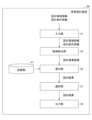
- FIG. 4 is a functional configuration diagram of a station design device according to the embodiment.
- the station design device 30 has an input unit 31, a candidate extraction unit 33, a derivation unit 35, a selection unit 37, and an output unit 39. Each of these units has a function that is realized by an instruction from the CPU 301 in FIG. 2 based on a program.
- the station design device 30 also has a storage unit 41 constructed from a RAM 303 or an SSD 304.
- the input unit 31 inputs design environment information and design condition information from the communication terminal 50 .
- the "design environment information” includes information showing the size of the area for which the station is designed, the size and location of structures, whether or not there is obstruction, a 3D map of the area, etc.
- the "design condition information” includes information indicating the type of wireless communication method (5G, Wi-Fi, etc.) to be installed as a base station, the number of base stations that can be installed (inventory number, etc.), the positions (candidate base station installation positions) and directions in which base stations can be installed within the area targeted for station design, and the evaluation positions for communication quality (signal strength) within the area targeted for station design.
- the "wireless communication method” may also be simply referred to as the "communication method.”
- the area for which station placement is designed may, for example, be one floor of a building or a location section of an outdoor exhibition hall. Also, for example, one floor may be divided into multiple areas, with different modes set for each area.
- the information included in the design environment information and the design condition information may be other than the examples given above.
- FIG. 5 is a conceptual diagram of the station placement design target area.
- an indoor area is described, but an outdoor area may also be used.
- multiple installation position candidates c1 to c6 are set at various points on the ceiling, radio wave quality evaluation positions e1 at various points on the floor, and structures s1, etc.
- installation position candidates c1 to c6 are collectively referred to as “installation position candidates c.”
- the evaluation position e1 and the like are collectively referred to as “evaluation position e.”
- structure s1 and the like are collectively referred to as “structure s.”
- the numbers of installation position candidates c, evaluation positions e, and structures s shown in FIG. 5 are merely examples, and are not limited to the numbers shown in FIG. 5.
- the station placement design device 30 of the embodiment selects one or more optimal installation position candidates c for the 5G base station from the multiple installation position candidates c.
- the station placement design device 30 may also select one or more optimal installation position candidates c for the Wi-Fi base station from the multiple installation position candidates c.
- the candidate extraction unit 33 estimates the received power (radio wave intensity) by performing radio wave propagation estimation (simulation) such as ray tracing using a 3D model. Specifically, the candidate extraction unit 33 estimates the received power at each evaluation position for each combination by performing radio wave propagation estimation for each evaluation position at which 5G radio waves can be received from each base station related to each combination of 5G antennas of a predetermined type when installed in a predetermined installation direction at a predetermined installation position candidate based on the design environment information and design condition information.
- radio wave propagation estimation simulation
- the throughput may be predicted from a conversion table of received power and throughput that is prepared in advance by acquiring experimental data or by link level simulation, for example.
- the derivation unit 35 uses the evaluation function f to derive a design result evaluation value by using a conversion table corresponding to each wireless communication method based on the estimated received power value of each wireless communication method included in the design result candidate d i according to the following (Equation 1).
- the derivation unit 35 calculates the sum of the design result evaluation values at each evaluation position for each design result candidate di . Instead of calculating the sum, the minimum value of the design result evaluation value at each evaluation position may be derived for each design result candidate di.
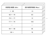
- FIG. 6 is a diagram showing a conversion table for each wireless communication method.
- the wireless communication methods include Wi-Fi (wireless LAN) standards such as 2.4 GHz band, 5 GHz band, and 6 GHz band, and cellular standards such as 4G, 5G, and 6G.
- Wi-Fi wireless LAN
- cellular standards such as 4G, 5G, and 6G.
- the reception power range and the design result evaluation value r i are associated and managed. Therefore, when different bands are used even if the same standard is used, such as a conversion table for the Wi-Fi standard in the 2.4 GHz band and a conversion table for the Wi-Fi standard in the 5 GHz band, the derivation unit 35 refers to different conversion tables.
- the present embodiment treats them as different wireless communication methods, and the conversion tables are also different.
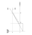
- FIG. 7 is a graph of the values in the conversion table.
- the solid line indicates the values according to the proposal of this embodiment (present proposal), and the dashed line indicates the values according to the conventional technology.
- the design result evaluation value becomes a constant value of - ⁇ .
- a lower limit specified value e.g., -82 dBm
- a single design result evaluation value corresponds to each of the predetermined ranges that differ in stages.
- the design result evaluation value corresponds to a constant value of 78 Mbps.
- the upper limit specified value is an example of a first specified value
- the corresponding design result evaluation value is an example of a first design result evaluation value
- the lower limit specified value is an example of a second specified value
- the corresponding design result evaluation value is an example of a second design result evaluation value.
- the selection unit 37 selects as design results a top predetermined number of design result candidates di having the highest sum of the design result evaluation value ri from among the design result candidates di extracted by the candidate extraction unit 33. Note that when the derivation unit 35 derives the minimum value of the design result evaluation value without calculating the sum of the design result evaluation value, the selection unit 37 selects the design result having the largest minimum value of the design result evaluation value.
- the output unit 39 outputs the final design result. Examples of the output include displaying on a display connected to the station design device 30, printing on a printer or the like connected to the station design device 30, or transmitting to the communication terminal 50 via the communication network 100.
- Fig. 8 is a flowchart showing a station placement design method executed by the station placement design device according to the embodiment.
- the input unit 31 inputs design environment information and design condition information from a communication terminal 50 or the like.
- the derivation unit 35 derives each design result evaluation value ri based on the value of the received power included in the design result candidate d i using the evaluation function f, and calculates the sum of the design result evaluation values ri at each evaluation position for each design result candidate d i .
- the selection unit 37 selects, as design results, a top predetermined number of design result candidates d i having high design result evaluation values r i from among the extracted design result candidates d i .
- the present invention is not limited to the above-described embodiment, and may have the following configurations or processes (operations).
- the station design device 30 can be realized by a computer and a program, but this program can also be recorded on a (non-temporary) recording medium or provided via the communication network 100.
- a notebook computer is shown as an example of a communication terminal 50, but this is not limited thereto.
- the communication terminal 50 may be a desktop computer, a tablet terminal, a smartphone, a smartwatch, a car navigation device, a refrigerator, a microwave oven, etc.
- Each CPU 301, 501 may be multiple, not just single.
- the candidate extraction unit 33 estimates the received power at each evaluation position e by radio wave propagation estimation (simulation) such as ray tracing using a 3D model, but this is not limited to this.
- the radio wave propagation estimation unit 32 may, for example, actually measure and predict the received power (radio wave intensity) by calibrating the radio wave propagation estimation result based on actual measurement data at each evaluation position (part of it).
Landscapes
- Engineering & Computer Science (AREA)
- Computer Networks & Wireless Communication (AREA)
- Signal Processing (AREA)
- Mobile Radio Communication Systems (AREA)
Abstract
Description
本開示は、無線通信の基地局を設置する際の設計技術に関する。 This disclosure relates to design techniques for installing wireless communication base stations.
一般的に、セルラーや無線LAN(Local Area Network)等の無線通信のカバーエリアを構築するため、基地局の設置位置やアンテナ方向を決める置局設計が行われる。置局設計では、基地局の配置を選定した上で、カバーエリアのシミュレーション評価を行う際、レイトレーシング法(非特許文献1)などの方法が用いられる。この方法は受信電力を基準としており、得られた受信電力の値をリニア(線形)に用いて設計結果の評価が行われていた。 Generally, to build a coverage area for wireless communication such as cellular or wireless LAN (Local Area Network), station placement design is carried out to determine the installation location of base stations and the direction of antennas. In station placement design, after selecting the location of the base stations, methods such as the ray tracing method (Non-Patent Document 1) are used to perform a simulation evaluation of the coverage area. This method is based on received power, and the design results are evaluated linearly using the obtained received power values.
ところが、実際には受信電力が変化した際に得られる伝送速度の範囲は無線通信方式の伝送特性として予め定められており、受信電力の値が上限の所定値(例えば、-59dBm)以上になった場合には、伝送速度は受信電力の値に比例して速くなる訳ではなく頭打ちとなる。そのため、従来の置局設計方法では、本来必要な受信電力よりも過剰な受信電力にする設計結果が得られることがあった。逆に、受信電力の値が下限の所定値(例えば、-82dBM)未満になった場合には、どのような受信電力の値であっても、受信位置(評価位置)まで通信可能な強度の電波が届かないために通信不可になってしまう。そのため、従来の置局設計方法では、実際には通信不可にも関わらず、通信が不安定ではあるが通信可能な受信電力として設計結果が得られることがあった。 However, in reality, the range of transmission speeds that can be obtained when the received power changes is predetermined as the transmission characteristics of the wireless communication method, and when the received power value exceeds a specified upper limit (e.g., -59 dBm), the transmission speed does not increase in proportion to the received power value but reaches a plateau. For this reason, conventional station placement design methods sometimes obtained design results that result in a received power that is greater than the actually required received power. Conversely, when the received power value falls below a specified lower limit (e.g., -82 dBM), communication is impossible regardless of the received power value because radio waves of sufficient strength for communication do not reach the receiving position (evaluation position). For this reason, conventional station placement design methods sometimes obtained design results with a received power that allows communication, albeit unstable, even when communication is actually impossible.
上述のように、実際の状況に合った置局設計を行うことができないという課題があった。 As mentioned above, there was an issue of not being able to design stations to suit actual conditions.
本発明は、上述の点に鑑みてなされたものであって、無線通信方式の伝送特性に応じた置局設計を行うことを目的とする。 The present invention was made in consideration of the above points, and aims to perform station placement design according to the transmission characteristics of a wireless communication system.
上記課題を解決するため、請求項1に係る発明は、無線通信の基地局の設置に関する設計を行う置局設計装置であって、前記設計の際の評価位置における受信電力の値が第1の所定値以上の場合には、一定値となる第1の設計結果評価値を導出する導出部を有する置局設計装置である。 In order to solve the above problem, the invention of claim 1 is a station location design device that designs the installation of a wireless communication base station, and has a derivation unit that derives a first design result evaluation value that is a constant value when the value of the received power at the evaluation position during the design is equal to or greater than a first predetermined value.
以上説明したように本発明によれば、無線通信方式の伝送特性に応じた置局設計を行うことができるという効果を奏する。 As described above, the present invention has the effect of enabling station placement design according to the transmission characteristics of a wireless communication system.
以下、図面に基づいて本発明の実施形態を説明する。 Below, an embodiment of the present invention will be explained with reference to the drawings.
〔実施形態のシステム構成〕
まず、図1を用いて、実施形態の通信システムの全体構成について説明する。図1は、本施形態に係る通信システムの全体構成図である。
[System configuration of the embodiment]
First, the overall configuration of a communication system according to an embodiment will be described with reference to Fig. 1. Fig. 1 is a diagram showing the overall configuration of a communication system according to the embodiment.
図1に示されているように、実施形態の通信システム10は、置局設計装置30、及び通信端末50によって構築されている。通信端末50は、ユーザによって管理及び使用される。ユーザは、置局設計装置30の出力結果を参照して、その後の対応を判断する者である。
As shown in FIG. 1, the communication system 10 of the embodiment is constructed by a station
また、置局設計装置30と通信端末50は、インターネット等の通信ネットワーク100を介して通信することができる。通信ネットワーク100の接続形態は、無線又は有線のいずれでも良い。
The
置局設計装置30は、単数又は複数のコンピュータによって構成されている。置局設計装置30が複数のコンピュータによって構成されている場合には、「置局設計装置」と示しても良いし、「置局設計システム」と示しても良い。置局設計装置30は、無線通信の基地局の設置に関する設計を行う装置である。
The station
通信端末50は、コンピュータであり、図1では、一例としてノート型パソコンが示されている。図1では、ユーザが、通信端末50を操作する。なお、通信端末50を用いずに、置局設計装置30単独で処理をしてもよい。
The
〔ハードウェア構成〕
<置局設計装置のハードウェア構成>
次に、図2を用いて、置局設計装置30の電気的なハードウェア構成を説明する。図2は、置局設計装置の電気的なハードウェア構成図である。
[Hardware configuration]
<Hardware configuration of station design device>
Next, the electrical hardware configuration of the station
置局設計装置30は、コンピュータとして、図2に示されているように、プロセッサとしてのCPU(Central Processing Unit)301、ROM(Read Only Memory)302、RAM(Random Access Memory)303、SSD(Solid State Drive)304、外部機器接続I/F(Interface)305、ネットワークI/F306、メディアI/F309、及びバスライン310を備えている。
As shown in FIG. 2, the
これらのうち、CPU301は、置局設計装置30全体の動作を制御する。ROM302は、IPL(Initial Program Loader)等のCPU301の駆動に用いられるプログラムを記憶する。RAM303は、CPU301のワークエリアとして使用される。
Of these,
SSD304は、CPU301の制御に従って各種データの読み出し又は書き込みを行う。なお、SSD304の代わりに、HDD(Hard Disk Drive)を用いても良い。
The
外部機器接続I/F305は、各種の外部機器を接続するためのインターフェースである。この場合の外部機器は、ディスプレイ、スピーカ、キーボード、マウス、USB(Universal Serial Bus)メモリ、及びプリンタ等である。 The external device connection I/F 305 is an interface for connecting various external devices. In this case, the external devices include a display, a speaker, a keyboard, a mouse, a USB (Universal Serial Bus) memory, and a printer.
ネットワークI/F306は、通信ネットワーク100を介してデータ通信をするためのインターフェースである。
The network I/F 306 is an interface for data communication via the
メディアI/F309は、フラッシュメモリ等の記録メディア309mに対するデータの読み出し又は書き込み(記憶)を制御する。記録メディア309mには、DVD(Digital Versatile Disc)やBlu-ray Disc(登録商標)等も含まれる。
The media I/
バスライン310は、図2に示されているCPU301等の各構成要素を電気的に接続するためのアドレスバスやデータバス等である。
The
<通信端末のハードウェア構成>
次に、図3を用いて、通信端末50の電気的なハードウェア構成を説明する。図3は、通信端末の電気的なハードウェア構成図である。
<Hardware configuration of communication terminal>
Next, the electrical hardware configuration of the
通信端末50は、コンピュータとして、図3に示されているように、CPU501、ROM502、RAM503、SSD504、外部機器接続I/F(Interface)505、ネットワークI/F506、ディスプレイ507、入力デバイス508、メディアI/F509、及びバスライン510を備えている。
As shown in FIG. 3, the
これらのうち、CPU501は、通信端末50全体の動作を制御する。ROM502は、IPL等のCPU501の駆動に用いられるプログラムを記憶する。RAM503は、CPU501のワークエリアとして使用される。
Of these,
SSD504は、CPU501の制御に従って各種データの読み出し又は書き込みを行う。なお、SSD504の代わりに、HDD(Hard Disk Drive)を用いてもよい。
The SSD 504 reads and writes various data under the control of the
外部機器接続I/F505は、各種の外部機器を接続するためのインターフェースである。この場合の外部機器は、ディスプレイ、スピーカ、キーボード、マウス、USBメモリ、及びプリンタ等である。
The external device connection I/
ネットワークI/F506は、通信ネットワーク100を介してデータ通信をするためのインターフェースである。
The network I/F 506 is an interface for data communication via the
ディスプレイ507は、各種画像を表示する液晶や有機EL(Electro Luminescence)などの表示手段の一種である。
入力デバイス508は、キーボード、ポインティングデバイス等であり、各種指示の選択や実行、処理対象の選択、カーソルの移動などを行う入力手段の一種である。なお、ユーザがキーボードを使う場合は、ポインティングデバイスの機能をOFFにしてもよい。
The
メディアI/F509は、フラッシュメモリ等の記録メディア509mに対するデータの読み出し又は書き込み(記憶)を制御する。記録メディア509mには、DVDやBlu-ray Disc(登録商標)等も含まれる。
The media I/
バスライン510は、図3に示されているCPU501等の各構成要素を電気的に接続するためのアドレスバスやデータバス等である。
The
〔実施形態の機能構成〕
図4は、実施形態に係る置局設計装置の機能構成図である。
[Functional configuration of the embodiment]
FIG. 4 is a functional configuration diagram of a station design device according to the embodiment.
図4に示すように、置局設計装置30は、入力部31、候補抽出部33、導出部35、選択部37、及び出力部39を有している。これら各部は、プログラムに基づき図2のCPU301による命令によって実現される機能である。また、置局設計装置30は、RAM303又はSSD304によって構築された記憶部41を有している。
As shown in FIG. 4, the
<入力部>
入力部31は、通信端末50から、設計環境情報、及び設計条件情報を入力する。
<Input section>
The
「設計環境情報」には、置局設計対象エリアの広さ、構造物の大きさや位置、遮蔽の有無、エリアの3Dマップ等を示す情報が含まれている。 The "design environment information" includes information showing the size of the area for which the station is designed, the size and location of structures, whether or not there is obstruction, a 3D map of the area, etc.
「設計条件情報」には、基地局として設置される無線通信方式の種類(5G、Wi-Fi等)、基地局の設置可能数(在庫数等)、置局設計対象エリア内で基地局を設置可能な位置(基地局の設置位置候補)及び方向、並びに置局設計対象エリア内における通信品質(電波強度)の評価位置を示す情報等が含まれている。なお、本実施形態では、「無線通信方式」は単に「通信方式」と示す場合もある。 The "design condition information" includes information indicating the type of wireless communication method (5G, Wi-Fi, etc.) to be installed as a base station, the number of base stations that can be installed (inventory number, etc.), the positions (candidate base station installation positions) and directions in which base stations can be installed within the area targeted for station design, and the evaluation positions for communication quality (signal strength) within the area targeted for station design. Note that in this embodiment, the "wireless communication method" may also be simply referred to as the "communication method."
なお、置局設計対象エリアは、例えば、ビルの1フロア、野外の展示場の位置区画等を示す。また、例えば、1フロアを複数のエリアに分割し、エリア毎に異なるモードが設定されていてもよい。設計環境情報、及び設計条件情報に含まれている各情報は、上記の例以外であってもよい。 The area for which station placement is designed may, for example, be one floor of a building or a location section of an outdoor exhibition hall. Also, for example, one floor may be divided into multiple areas, with different modes set for each area. The information included in the design environment information and the design condition information may be other than the examples given above.
<候補抽出部>
候補抽出部33は、入力部31から取得した設計環境情報及び設計条件情報に基づき、置局設計対象エリア内において、どの設置位置候補にどの無線通信装置を設置すると、どの程度の通信品質になるかを算出(評価)することで、複数(i=1,2,…,I)の置局設計結果候補を算出する。
<Candidate Extraction Unit>
The
ここで、図5を用いて、置局設計対象エリアについて説明する。図5は、置局設計対象エリアの概念図である。図5では、屋内のエリアについて説明するが、屋外のエリアであってもよい。図5に示すように、置局設計対象エリア内には、天井の各所における複数の設置位置候補c1~c6、床の各所における電波品質の評価位置e1等、及び構造物s1等が設定されている。 Here, the station placement design target area will be described using FIG. 5. FIG. 5 is a conceptual diagram of the station placement design target area. In FIG. 5, an indoor area is described, but an outdoor area may also be used. As shown in FIG. 5, within the station placement design target area, multiple installation position candidates c1 to c6 are set at various points on the ceiling, radio wave quality evaluation positions e1 at various points on the floor, and structures s1, etc.
なお、設置位置候補c1~c6の総称を「設置位置候補c」と示す。評価位置e1等の総称を「評価位置e」と示す。また、構造物s1等の総称を「構造物s」と示す。また、図5に示す設置位置候補c、評価位置e、及び構造物sの各数は一例であって、図5に示されている数に限らない。 Note that the installation position candidates c1 to c6 are collectively referred to as "installation position candidates c." The evaluation position e1 and the like are collectively referred to as "evaluation position e." Furthermore, the structure s1 and the like are collectively referred to as "structure s." Furthermore, the numbers of installation position candidates c, evaluation positions e, and structures s shown in FIG. 5 are merely examples, and are not limited to the numbers shown in FIG. 5.
実施形態の置局設計装置30は、複数の設置位置候補cから、5Gの基地局に最適な設置位置候補cを1つ又は複数選択する。また、置局設計装置30は、複数の設置位置候補cから、Wi-Fiの基地局に最適な設置位置候補cを1つ又は複数選択してもよい。
The station
続いて、図4に戻り、候補抽出部33は、3Dモデルを用いたレイトレーシング等の電波伝搬推定(シミュレーション)を行うことで、受信電力(電波強度)を推定する。具体的には、候補抽出部33は、設計環境情報及び設計条件情報に基づいて、所定の設置位置候補で所定の設置方向に設置された場合の所定の種類の5Gのアンテナの各組合せに係る各基地局から、5Gの電波が受信可能な各評価位置に対する電波伝搬推定を行うことで、各組合せに対する各評価位置での受信電力を推定する。または、候補抽出部33は、設計環境情報及び設計条件情報に基づいて、所定の設置位置候補で所定の設置方向に設置された場合の所定の種類のAPの装置の各組合せに係る基地局から、Wi-Fiの電波が受信可能な各評価位置に対する電波伝搬推定を行うことで、各組合せに対する各評価位置での受信電力を推定する。例えば、天井の設置位置候補が6つで、設置方向が4方向で、5Gのアンテナの種類が2つで、床の評価位置が10カ所の場合、候補抽出部33は、480回(=6×4×2×10)の計算により受信電力を推定する。また、天井の設置位置候補が6つで、設置方向が4方向で、APの装置の種類が3で、床の評価位置が10カ所の場合、候補抽出部33は、720回(=6×4×3×10)の計算により受信電力を推定する。
Next, returning to FIG. 4, the
なお、電波伝搬推定部32が受信電力ではなく、スループットを算出する場合は、例えば、実験データの取得又はリンクレベルシミュレーションにより予め用意した受信電力とスループットの換算表からスループットを予測してもよい。 In addition, when the radio wave propagation estimation unit 32 calculates the throughput instead of the received power, the throughput may be predicted from a conversion table of received power and throughput that is prepared in advance by acquiring experimental data or by link level simulation, for example.
<導出部>
導出部35は、評価関数fを用いて、以下に示す(式1)により、設計結果候補diに含まれる推定された各無線通信方式の受信電力の値に基づき、各無線通信方式に応じた変換テーブルを用いて設計結果評価値を導出する。
<Outlet part>
The
ri = f(di)・・・(式1)
そして、導出部35は、設計結果候補di毎に各評価位置における設計結果評価値の和を算出する。なお、導出部35は、設計結果候補di毎に各評価位置における設計結果評価値の和を算出せずに、設計結果候補di毎に各評価位置における設計結果評価値の最小値を導出してもよい。
r i = f(d i )...(Formula 1)
Then, the
ここで、図6を用いて、変換テーブルについて説明する。 Here, we will explain the conversion table using Figure 6.
(変換テーブル)
図6は、無線通信方式毎の変換テーブルを示した図である。各変換テーブルは記憶部41に記憶されている。無線通信方式には、2.4GHz帯、5GHz帯、6GHz帯等の各Wi-Fi(無線LAN)規格、及び4G、5G、6G等の各セルラー規格がある。各変換テーブルでは、受信電力範囲と設計結果評価値riが関連付けて管理されている。そのため、2.4GHz帯のWi-Fi規格用の変換テーブル、5GHz帯のWi-Fi規格用の変換テーブルのように、同じ規格であっても異なる帯域を利用する場合には、導出部35は異なる変換テーブルを参照する。また、例えば、同じ5Gのセルラー規格であっても基地局のアンテナ数が異なる場合には、本実施形態では異なる無線通信方式として扱い、変換テーブルも異なる。
(Conversion table)
FIG. 6 is a diagram showing a conversion table for each wireless communication method. Each conversion table is stored in the
図6では、一例として、受信電力範囲が2.4GHz帯のWi-Fi規格の変換テーブルが示されている。 In Figure 6, as an example, a conversion table for a Wi-Fi standard with a reception power range of 2.4 GHz is shown.
また、図7は、変換テーブルの値をグラフ化した図である。図7において、実線が本実施形態の案(本案)による値を示し、破線が従来技術による値を示す。 FIG. 7 is a graph of the values in the conversion table. In FIG. 7, the solid line indicates the values according to the proposal of this embodiment (present proposal), and the dashed line indicates the values according to the conventional technology.
図7に示すように、受信電力が下限の所定値(例えば-82dBm)未満になると設計結果評価値が一定値である-∞になる。受信電力が-82dBm以上からは、段階的に異なる所定の範囲毎に単一の設計結果評価値が対応する。そして、受信電力が上限の所定値(例えば-59dBm)以上では、設計結果評価値が一定値である78Mbpsが対応する。 As shown in Figure 7, when the received power falls below a lower limit specified value (e.g., -82 dBm), the design result evaluation value becomes a constant value of -∞. When the received power is -82 dBm or higher, a single design result evaluation value corresponds to each of the predetermined ranges that differ in stages. Then, when the received power is above the upper limit specified value (e.g., -59 dBm), the design result evaluation value corresponds to a constant value of 78 Mbps.
なお、上限の所定値は第1の所定値の一例であり、これに対応する設計結果評価値が第1の設計結果評価値の一例である。また、下限の所定値は第2の所定値の一例であり、これに対応する設計結果評価値が第2の設計結果評価値の一例である。 The upper limit specified value is an example of a first specified value, and the corresponding design result evaluation value is an example of a first design result evaluation value. The lower limit specified value is an example of a second specified value, and the corresponding design result evaluation value is an example of a second design result evaluation value.
<選択部>
図4に戻り、選択部37は、候補抽出部33によって抽出された設計結果候補diのうち、設計結果評価値riの和が高い上位所定数の設計結果候補diを設計結果として選択する。なお、導出部35が、設計結果評価値の和を算出せずに、設計結果評価値の最小値を導出する場合、選択部37は、設計結果評価値の最小値が最大となる設計結果を選択する。
<Selection section>
4, the
<出力部>
出力部39は、最終的な設計結果を出力する。出力の例としては、置局設計装置30に接続されたディスプレイへの表示、置局設計装置30に接続されたプリンタ等での印刷、又は、通信ネットワーク100を介して通信端末50への送信等が挙げられる。
<Output section>
The
〔実施形態の処理又は動作〕
続いて、図8を用いて、置局設計装置30の処理又は動作について説明する。図8は、実施形態に係る置局設計装置が実行する置局設計方法を示すフローチャートである。
[Processing or Operation of the Embodiment]
Next, the process or operation of the station
S10:入力部31は、通信端末50等から、設計環境情報、及び設計条件情報を入力する。
S10: The
S11:候補抽出部33は、設計環境情報、設計条件情報に基づき、複数(i=1,2,…,I)の設計結果候補を抽出する。
S11: The
S12:導出部35は、評価関数fを用いて、設計結果候補diに含まれる受信電力の値に基づいて各設計結果評価値riを導出し、設計結果候補di毎に各評価位置における設計結果評価値riの和を算出する。
S12: The
S13:選択部37は、抽出された設計結果候補diのうち、設計結果評価値riが高い上位所定数の設計結果候補diを設計結果として選択する。
S13: The
S14:出力部39は、設定結果を出力する。
S14: The
〔実施形態の効果〕
以上説明したように本実施形態によれば、無線通信方式の伝送特性に応じた置局設計を行うことができるという効果を奏する。
[Effects of the embodiment]
As described above, according to this embodiment, it is possible to perform station placement design in accordance with the transmission characteristics of a wireless communication system.
〔補足〕
本発明は上述の実施形態に限定されるものではなく、以下に示すような構成又は処理(動作)であってもよい。
〔supplement〕
The present invention is not limited to the above-described embodiment, and may have the following configurations or processes (operations).
(1)置局設計装置30はコンピュータとプログラムによっても実現できるが、このプログラムを(非一時的な)記録媒体に記録することも、通信ネットワーク100を介して提供することも可能である。
(1) The
(2)上記実施形態では、通信端末50の一例としてノート型パソコンが示されているが、これに限るものではなく、例えば、デスクトップパソコン、タブレット端末、スマートフォン、スマートウォッチ、カーナビゲーション装置、冷蔵庫、電子レンジ等であってもよい。
(2) In the above embodiment, a notebook computer is shown as an example of a
(3)各CPU301,501は、単一だけでなく、複数であってもよい。
(3) Each
(4)上記各実施形態では、候補抽出部33は、3Dモデルを用いたレイトレーシングなどの電波伝搬推定(シミュレーション)により各評価位置eでの受信電力を推定したが、これに限るものではない。電波伝搬推定部32は、例えば、各評価位置(の一部)における実測定データに基づいて、電波伝搬推定結果をキャリブレーションすることで、受信電力(電波強度)の実測及び予測を行ってもよい。
(4) In each of the above embodiments, the
10 通信システム
30 置局設計装置
31 入力部
33 候補抽出部
35 導出部
37 選択部
39 出力部
41 記憶部
10
Claims (8)
前記設計の際の評価位置における受信電力の値が第1の所定値以上の場合には、一定値となる第1の設計結果評価値を導出する導出部を有する置局設計装置。 A station placement design device for designing the placement of a wireless communication base station,
The station design device has a derivation unit that derives a first design result evaluation value that is a constant value when a value of received power at an evaluation position during the design is equal to or greater than a first predetermined value.
前記受信電力の範囲と前記設計結果評価値との関係を示し、前記受信電力の値が前記第1の所定値以上の場合には前記第1の設計結果評価値が関連付けて管理されている変換テーブルが記憶された記憶部を有し、
前記導出部は、前記変換テーブルを用いて、前記設計結果評価値を導出する、
置局設計装置。 The station placement design device according to claim 1,
a storage unit that stores a conversion table that indicates a relationship between the range of the received power and the design result evaluation value, and that manages the first design result evaluation value in association with a value of the received power equal to or greater than the first predetermined value;
The derivation unit derives the design result evaluation value by using the conversion table.
Station placement design device.
前記設計の際の評価位置における受信電力の値が第2の所定値未満の場合には、一定値となる第2の設計結果評価値を導出する導出部を有する置局設計装置。 A station placement design device for designing the placement of a wireless communication base station,
The station design device has a derivation unit that derives a second design result evaluation value that is a constant value when the value of the received power at the evaluation position during the design is less than a second predetermined value.
前記受信電力の範囲と前記設計結果評価値との関係を示し、前記受信電力の値が前記第2の所定値未満の場合には前記第2の設計結果評価値が関連付けて管理されている変換テーブルが記憶された記憶部を有し、
前記導出部は、前記変換テーブルを用いて、前記設計結果評価値を導出する、
置局設計装置。 The station placement design device according to claim 3,
a storage unit that stores a conversion table that indicates a relationship between the range of the received power and the design result evaluation value, and that manages the second design result evaluation value in association with the value of the received power being less than the second predetermined value;
The derivation unit derives the design result evaluation value by using the conversion table.
Station placement design device.
前記設計の際の評価位置における受信電力の値が第1の所定値以上の場合には、一定値となる第1の設計結果評価値を導出し、前記設計の際の評価位置における受信電力の値が前記第1の所定値より低い第2の所定値未満の場合には、前記第1の設計結果評価値より低い一定値となる第2の設計結果評価値を導出する導出部を有する置局設計装置。 A station placement design device for designing the placement of a wireless communication base station,
a derivation unit that derives a first design result evaluation value that is a constant value when the value of the received power at the evaluation position during the design is equal to or greater than a first predetermined value, and derives a second design result evaluation value that is a constant value lower than the first design result evaluation value when the value of the received power at the evaluation position during the design is less than a second predetermined value that is lower than the first predetermined value.
前記受信電力の範囲と前記設計結果評価値との関係を示し、前記受信電力の値が前記第1の所定値以上の場合には前記第1の設計結果評価値が関連付けて管理されており、前記受信電力の値が前記第2の所定値未満の場合には前記第2の設計結果評価値が関連付けて管理されている変換テーブルが記憶された記憶部を有し、
前記導出部は、前記変換テーブルを用いて、前記設計結果評価値を導出する、
置局設計装置。 The station placement design device according to claim 5,
a storage unit that stores a conversion table that indicates a relationship between the range of the received power and the design result evaluation value, and in which, when the value of the received power is equal to or greater than the first predetermined value, the first design result evaluation value is associated and managed, and when the value of the received power is less than the second predetermined value, the second design result evaluation value is associated and managed,
The derivation unit derives the design result evaluation value by using the conversion table.
Station placement design device.
置局設計装置は、前記設計の際の評価位置における受信電力の値が第1の所定値以上の場合には、一定値となる第1の設計結果評価値を導出する、置局設計方法。 A station placement design method executed by a station placement design device that designs installation of a wireless communication base station,
the station design device derives a first design result evaluation value that is a constant value when a value of received power at an evaluation position during the design is equal to or greater than a first predetermined value.
Priority Applications (2)
| Application Number | Priority Date | Filing Date | Title |
|---|---|---|---|
| JP2025525886A JPWO2024252641A1 (en) | 2023-06-08 | 2023-06-08 | |
| PCT/JP2023/021429 WO2024252641A1 (en) | 2023-06-08 | 2023-06-08 | Station placement design device, station placement design method, and program |
Applications Claiming Priority (1)
| Application Number | Priority Date | Filing Date | Title |
|---|---|---|---|
| PCT/JP2023/021429 WO2024252641A1 (en) | 2023-06-08 | 2023-06-08 | Station placement design device, station placement design method, and program |
Publications (1)
| Publication Number | Publication Date |
|---|---|
| WO2024252641A1 true WO2024252641A1 (en) | 2024-12-12 |
Family
ID=93795728
Family Applications (1)
| Application Number | Title | Priority Date | Filing Date |
|---|---|---|---|
| PCT/JP2023/021429 Pending WO2024252641A1 (en) | 2023-06-08 | 2023-06-08 | Station placement design device, station placement design method, and program |
Country Status (2)
| Country | Link |
|---|---|
| JP (1) | JPWO2024252641A1 (en) |
| WO (1) | WO2024252641A1 (en) |
Citations (4)
| Publication number | Priority date | Publication date | Assignee | Title |
|---|---|---|---|---|
| JP2001285923A (en) * | 2000-03-31 | 2001-10-12 | Mitsubishi Electric Corp | Base station layout pattern determination method |
| JP2006246016A (en) * | 2005-03-03 | 2006-09-14 | Nippon Telegr & Teleph Corp <Ntt> | Transmission speed evaluation system, transmission speed evaluation method, transmission speed evaluation program, and recording medium |
| JP2019033441A (en) * | 2017-08-09 | 2019-02-28 | 富士通株式会社 | Management device, wireless communication system, and management method |
| JP2020170932A (en) * | 2019-04-02 | 2020-10-15 | 日本電信電話株式会社 | Wireless performance evaluation method and wireless performance evaluation system |
-
2023
- 2023-06-08 JP JP2025525886A patent/JPWO2024252641A1/ja active Pending
- 2023-06-08 WO PCT/JP2023/021429 patent/WO2024252641A1/en active Pending
Patent Citations (4)
| Publication number | Priority date | Publication date | Assignee | Title |
|---|---|---|---|---|
| JP2001285923A (en) * | 2000-03-31 | 2001-10-12 | Mitsubishi Electric Corp | Base station layout pattern determination method |
| JP2006246016A (en) * | 2005-03-03 | 2006-09-14 | Nippon Telegr & Teleph Corp <Ntt> | Transmission speed evaluation system, transmission speed evaluation method, transmission speed evaluation program, and recording medium |
| JP2019033441A (en) * | 2017-08-09 | 2019-02-28 | 富士通株式会社 | Management device, wireless communication system, and management method |
| JP2020170932A (en) * | 2019-04-02 | 2020-10-15 | 日本電信電話株式会社 | Wireless performance evaluation method and wireless performance evaluation system |
Also Published As
| Publication number | Publication date |
|---|---|
| JPWO2024252641A1 (en) | 2024-12-12 |
Similar Documents
| Publication | Publication Date | Title |
|---|---|---|
| US11227082B2 (en) | Installation location determination device and method for installation location determination of radio device | |
| US8233910B2 (en) | Wireless communication device, wireless communication method and program | |
| US10295649B2 (en) | Wireless signal identification | |
| JP6635902B2 (en) | Base stations, communication terminals, drones, programs | |
| US8731561B2 (en) | Area detection apparatus, area detection method and area detection recording medium | |
| US12004110B2 (en) | Automated detection of a radio node location change | |
| JP7823769B2 (en) | Station placement design device and program | |
| WO2022172332A1 (en) | Base station placement supporting device, base station placement supporting method and program | |
| JP2019205127A (en) | Radio wave propagation estimation apparatus and radio wave propagation estimation method | |
| WO2024252641A1 (en) | Station placement design device, station placement design method, and program | |
| JP6998724B2 (en) | Evaluation device for wireless communication system | |
| WO2024252523A1 (en) | Station placement design device, station placement design method, and program | |
| CN110120851B (en) | A method, device and system for reporting channel quality information | |
| CN108307485A (en) | wireless network scanning method, device, terminal device and storage medium | |
| CN114071623A (en) | A method, apparatus, device and storage medium for fast switching of 5G beams | |
| WO2025120855A1 (en) | Station placement design device, station placement design method, and program | |
| WO2024100810A1 (en) | Station placement design apparatus and program | |
| JP7068807B2 (en) | Evaluation device for wireless communication system | |
| WO2024236756A1 (en) | Station placement design device, station placement design method, and program | |
| WO2019010777A1 (en) | Frequency point selection method and related product | |
| JP5953562B2 (en) | Wireless relay system and wireless relay device | |
| JP6998721B2 (en) | Evaluation device for wireless communication system | |
| US12463696B2 (en) | Cellular network over the air user equipment beam management emulation and testing | |
| WO2025120824A1 (en) | Station installation design system, station installation design device, station installation design method, and program | |
| WO2024252684A1 (en) | Station placement design device, station placement design method, and program |
Legal Events
| Date | Code | Title | Description |
|---|---|---|---|
| 121 | Ep: the epo has been informed by wipo that ep was designated in this application |
Ref document number: 23940739 Country of ref document: EP Kind code of ref document: A1 |
|
| ENP | Entry into the national phase |
Ref document number: 2025525886 Country of ref document: JP Kind code of ref document: A |
|
| NENP | Non-entry into the national phase |
Ref country code: DE |