WO2024252641A1 - Dispositif de conception de placement de station, procédé de conception de placement de station et programme - Google Patents
Dispositif de conception de placement de station, procédé de conception de placement de station et programme Download PDFInfo
- Publication number
- WO2024252641A1 WO2024252641A1 PCT/JP2023/021429 JP2023021429W WO2024252641A1 WO 2024252641 A1 WO2024252641 A1 WO 2024252641A1 JP 2023021429 W JP2023021429 W JP 2023021429W WO 2024252641 A1 WO2024252641 A1 WO 2024252641A1
- Authority
- WO
- WIPO (PCT)
- Prior art keywords
- design
- value
- station
- received power
- result evaluation
- Prior art date
- Legal status (The legal status is an assumption and is not a legal conclusion. Google has not performed a legal analysis and makes no representation as to the accuracy of the status listed.)
- Pending
Links
Images


Classifications
-
- H—ELECTRICITY
- H04—ELECTRIC COMMUNICATION TECHNIQUE
- H04W—WIRELESS COMMUNICATION NETWORKS
- H04W16/00—Network planning, e.g. coverage or traffic planning tools; Network deployment, e.g. resource partitioning or cells structures
- H04W16/18—Network planning tools
-
- H—ELECTRICITY
- H04—ELECTRIC COMMUNICATION TECHNIQUE
- H04W—WIRELESS COMMUNICATION NETWORKS
- H04W24/00—Supervisory, monitoring or testing arrangements
- H04W24/06—Testing, supervising or monitoring using simulated traffic
Definitions
- This disclosure relates to design techniques for installing wireless communication base stations.
- station placement design is carried out to determine the installation location of base stations and the direction of antennas.
- methods such as the ray tracing method (Non-Patent Document 1) are used to perform a simulation evaluation of the coverage area. This method is based on received power, and the design results are evaluated linearly using the obtained received power values.
- the range of transmission speeds that can be obtained when the received power changes is predetermined as the transmission characteristics of the wireless communication method, and when the received power value exceeds a specified upper limit (e.g., -59 dBm), the transmission speed does not increase in proportion to the received power value but reaches a plateau.
- a specified upper limit e.g., -59 dBm
- the transmission speed does not increase in proportion to the received power value but reaches a plateau.
- a specified upper limit e.g., -59 dBm
- the transmission speed does not increase in proportion to the received power value but reaches a plateau.
- a specified lower limit e.g., -82 dBM
- communication is impossible regardless of the received power value because radio waves of sufficient strength for communication do not reach the receiving position (evaluation position).
- conventional station placement design methods sometimes obtained design results with a received power that allows communication, albeit unstable, even when communication is actually impossible.
- the present invention was made in consideration of the above points, and aims to perform station placement design according to the transmission characteristics of a wireless communication system.
- the invention of claim 1 is a station location design device that designs the installation of a wireless communication base station, and has a derivation unit that derives a first design result evaluation value that is a constant value when the value of the received power at the evaluation position during the design is equal to or greater than a first predetermined value.
- the present invention has the effect of enabling station placement design according to the transmission characteristics of a wireless communication system.
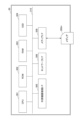
- FIG. 1 is an overall configuration diagram of a communication system according to an embodiment.
- FIG. 2 is an electrical hardware configuration diagram of the station design apparatus according to the embodiment.
- FIG. 2 is a diagram illustrating an electrical hardware configuration of a communication terminal according to the embodiment.
- FIG. 2 is a functional configuration diagram of a station design device according to an embodiment.
- FIG. 1 is a conceptual diagram of an area subject to station placement design.
- FIG. 13 is a conceptual diagram illustrating a conversion table.
- Fig. 1 is a diagram showing the overall configuration of a communication system according to the embodiment.
- the communication system 10 of the embodiment is constructed by a station placement design device 30 and a communication terminal 50.
- the communication terminal 50 is managed and used by a user.
- the user refers to the output result of the station placement design device 30 and decides on the next action to be taken.
- the station design device 30 and the communication terminal 50 can communicate with each other via a communication network 100 such as the Internet.
- the connection form of the communication network 100 may be either wireless or wired.
- the station placement design device 30 is composed of one or more computers. When the station placement design device 30 is composed of multiple computers, it may be referred to as a "station placement design device” or a "station placement design system.”
- the station placement design device 30 is a device that designs the installation of wireless communication base stations.
- the communication terminal 50 is a computer, and FIG. 1 shows a notebook computer as an example.
- a user operates the communication terminal 50.
- the station design device 30 may perform processing alone, without using the communication terminal 50.
- FIG. 2 is a diagram showing the electrical hardware configuration of the station placement design device.
- the station design device 30 is a computer equipped with a processor such as a CPU (Central Processing Unit) 301, a ROM (Read Only Memory) 302, a RAM (Random Access Memory) 303, an SSD (Solid State Drive) 304, an external device connection I/F (Interface) 305, a network I/F 306, a media I/F 309, and a bus line 310.
- a processor such as a CPU (Central Processing Unit) 301, a ROM (Read Only Memory) 302, a RAM (Random Access Memory) 303, an SSD (Solid State Drive) 304, an external device connection I/F (Interface) 305, a network I/F 306, a media I/F 309, and a bus line 310.
- a processor such as a CPU (Central Processing Unit) 301, a ROM (Read Only Memory) 302, a RAM (Random Access Memory) 303, an SSD (Solid State Drive) 304, an external device connection I/F (
- CPU 301 controls the operation of the entire station design device 30.
- ROM 302 stores programs used to drive CPU 301, such as IPL (Initial Program Loader).
- RAM 303 is used as a work area for CPU 301.
- the SSD 304 reads and writes various data according to the control of the CPU 301. Note that a HDD (Hard Disk Drive) may be used instead of the SSD 304.
- HDD Hard Disk Drive
- the external device connection I/F 305 is an interface for connecting various external devices.
- the external devices include a display, a speaker, a keyboard, a mouse, a USB (Universal Serial Bus) memory, and a printer.
- USB Universal Serial Bus
- the network I/F 306 is an interface for data communication via the communication network 100.
- the media I/F 309 controls the reading and writing (storing) of data to a recording medium 309m such as a flash memory.
- Recording media 309m includes DVDs (Digital Versatile Discs) and Blu-ray Discs (registered trademarks).
- the bus line 310 is an address bus, a data bus, etc., for electrically connecting each component such as the CPU 301 shown in FIG. 2.
- Fig. 3 is a diagram showing the electrical hardware configuration of the communication terminal.
- the communication terminal 50 is a computer and includes a CPU 501, a ROM 502, a RAM 503, an SSD 504, an external device connection I/F (Interface) 505, a network I/F 506, a display 507, an input device 508, a media I/F 509, and a bus line 510.
- CPU 501 controls the overall operation of communication terminal 50.
- ROM 502 stores programs used to drive CPU 501, such as IPL.
- RAM 503 is used as a work area for CPU 501.
- the SSD 504 reads and writes various data under the control of the CPU 501. Note that a HDD (Hard Disk Drive) may be used instead of the SSD 504.
- HDD Hard Disk Drive
- the external device connection I/F 505 is an interface for connecting various external devices.
- the external devices include a display, a speaker, a keyboard, a mouse, a USB memory, and a printer.
- the network I/F 506 is an interface for data communication via the communication network 100.
- Display 507 is a type of display means such as liquid crystal or organic EL (Electro Luminescence) that displays various images.
- the input device 508 is a keyboard, pointing device, etc., and is a type of input means for selecting and executing various instructions, selecting a processing target, moving the cursor, etc.
- the pointing device function may be turned off.
- the media I/F 509 controls the reading and writing (storing) of data from and to a recording medium 509m such as a flash memory.
- Recording media 509m includes DVDs and Blu-ray Discs (registered trademarks).
- the bus line 510 is an address bus, a data bus, etc., for electrically connecting each component such as the CPU 501 shown in FIG. 3.
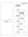
- FIG. 4 is a functional configuration diagram of a station design device according to the embodiment.
- the station design device 30 has an input unit 31, a candidate extraction unit 33, a derivation unit 35, a selection unit 37, and an output unit 39. Each of these units has a function that is realized by an instruction from the CPU 301 in FIG. 2 based on a program.
- the station design device 30 also has a storage unit 41 constructed from a RAM 303 or an SSD 304.
- the input unit 31 inputs design environment information and design condition information from the communication terminal 50 .
- the "design environment information” includes information showing the size of the area for which the station is designed, the size and location of structures, whether or not there is obstruction, a 3D map of the area, etc.
- the "design condition information” includes information indicating the type of wireless communication method (5G, Wi-Fi, etc.) to be installed as a base station, the number of base stations that can be installed (inventory number, etc.), the positions (candidate base station installation positions) and directions in which base stations can be installed within the area targeted for station design, and the evaluation positions for communication quality (signal strength) within the area targeted for station design.
- the "wireless communication method” may also be simply referred to as the "communication method.”
- the area for which station placement is designed may, for example, be one floor of a building or a location section of an outdoor exhibition hall. Also, for example, one floor may be divided into multiple areas, with different modes set for each area.
- the information included in the design environment information and the design condition information may be other than the examples given above.
- FIG. 5 is a conceptual diagram of the station placement design target area.
- an indoor area is described, but an outdoor area may also be used.
- multiple installation position candidates c1 to c6 are set at various points on the ceiling, radio wave quality evaluation positions e1 at various points on the floor, and structures s1, etc.
- installation position candidates c1 to c6 are collectively referred to as “installation position candidates c.”
- the evaluation position e1 and the like are collectively referred to as “evaluation position e.”
- structure s1 and the like are collectively referred to as “structure s.”
- the numbers of installation position candidates c, evaluation positions e, and structures s shown in FIG. 5 are merely examples, and are not limited to the numbers shown in FIG. 5.
- the station placement design device 30 of the embodiment selects one or more optimal installation position candidates c for the 5G base station from the multiple installation position candidates c.
- the station placement design device 30 may also select one or more optimal installation position candidates c for the Wi-Fi base station from the multiple installation position candidates c.
- the candidate extraction unit 33 estimates the received power (radio wave intensity) by performing radio wave propagation estimation (simulation) such as ray tracing using a 3D model. Specifically, the candidate extraction unit 33 estimates the received power at each evaluation position for each combination by performing radio wave propagation estimation for each evaluation position at which 5G radio waves can be received from each base station related to each combination of 5G antennas of a predetermined type when installed in a predetermined installation direction at a predetermined installation position candidate based on the design environment information and design condition information.
- radio wave propagation estimation simulation
- the throughput may be predicted from a conversion table of received power and throughput that is prepared in advance by acquiring experimental data or by link level simulation, for example.
- the derivation unit 35 uses the evaluation function f to derive a design result evaluation value by using a conversion table corresponding to each wireless communication method based on the estimated received power value of each wireless communication method included in the design result candidate d i according to the following (Equation 1).
- the derivation unit 35 calculates the sum of the design result evaluation values at each evaluation position for each design result candidate di . Instead of calculating the sum, the minimum value of the design result evaluation value at each evaluation position may be derived for each design result candidate di.
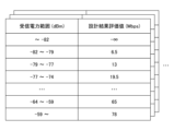
- FIG. 6 is a diagram showing a conversion table for each wireless communication method.
- the wireless communication methods include Wi-Fi (wireless LAN) standards such as 2.4 GHz band, 5 GHz band, and 6 GHz band, and cellular standards such as 4G, 5G, and 6G.
- Wi-Fi wireless LAN
- cellular standards such as 4G, 5G, and 6G.
- the reception power range and the design result evaluation value r i are associated and managed. Therefore, when different bands are used even if the same standard is used, such as a conversion table for the Wi-Fi standard in the 2.4 GHz band and a conversion table for the Wi-Fi standard in the 5 GHz band, the derivation unit 35 refers to different conversion tables.
- the present embodiment treats them as different wireless communication methods, and the conversion tables are also different.
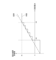
- FIG. 7 is a graph of the values in the conversion table.
- the solid line indicates the values according to the proposal of this embodiment (present proposal), and the dashed line indicates the values according to the conventional technology.
- the design result evaluation value becomes a constant value of - ⁇ .
- a lower limit specified value e.g., -82 dBm
- a single design result evaluation value corresponds to each of the predetermined ranges that differ in stages.
- the design result evaluation value corresponds to a constant value of 78 Mbps.
- the upper limit specified value is an example of a first specified value
- the corresponding design result evaluation value is an example of a first design result evaluation value
- the lower limit specified value is an example of a second specified value
- the corresponding design result evaluation value is an example of a second design result evaluation value.
- the selection unit 37 selects as design results a top predetermined number of design result candidates di having the highest sum of the design result evaluation value ri from among the design result candidates di extracted by the candidate extraction unit 33. Note that when the derivation unit 35 derives the minimum value of the design result evaluation value without calculating the sum of the design result evaluation value, the selection unit 37 selects the design result having the largest minimum value of the design result evaluation value.
- the output unit 39 outputs the final design result. Examples of the output include displaying on a display connected to the station design device 30, printing on a printer or the like connected to the station design device 30, or transmitting to the communication terminal 50 via the communication network 100.
- Fig. 8 is a flowchart showing a station placement design method executed by the station placement design device according to the embodiment.
- the input unit 31 inputs design environment information and design condition information from a communication terminal 50 or the like.
- the derivation unit 35 derives each design result evaluation value ri based on the value of the received power included in the design result candidate d i using the evaluation function f, and calculates the sum of the design result evaluation values ri at each evaluation position for each design result candidate d i .
- the selection unit 37 selects, as design results, a top predetermined number of design result candidates d i having high design result evaluation values r i from among the extracted design result candidates d i .
- the present invention is not limited to the above-described embodiment, and may have the following configurations or processes (operations).
- the station design device 30 can be realized by a computer and a program, but this program can also be recorded on a (non-temporary) recording medium or provided via the communication network 100.
- a notebook computer is shown as an example of a communication terminal 50, but this is not limited thereto.
- the communication terminal 50 may be a desktop computer, a tablet terminal, a smartphone, a smartwatch, a car navigation device, a refrigerator, a microwave oven, etc.
- Each CPU 301, 501 may be multiple, not just single.
- the candidate extraction unit 33 estimates the received power at each evaluation position e by radio wave propagation estimation (simulation) such as ray tracing using a 3D model, but this is not limited to this.
- the radio wave propagation estimation unit 32 may, for example, actually measure and predict the received power (radio wave intensity) by calibrating the radio wave propagation estimation result based on actual measurement data at each evaluation position (part of it).
Landscapes
- Engineering & Computer Science (AREA)
- Computer Networks & Wireless Communication (AREA)
- Signal Processing (AREA)
- Mobile Radio Communication Systems (AREA)
Abstract
Le but de la présente divulgation est de réaliser une conception de placement de station correspondant à la caractéristique de transmission d'un système de communication sans fil. À cet effet, dans la présente divulgation, l'invention selon la revendication 1 concerne un dispositif de conception de placement de station servant à réaliser une conception relative au placement d'une station de base pour une communication sans fil, le dispositif de conception de placement de station comprenant une unité de dérivation qui dérive une première valeur d'évaluation de résultat de conception qui est une valeur constante si la valeur de la puissance reçue à une position d'évaluation pendant la conception est supérieure ou égale à une première valeur prédéterminée.
Priority Applications (2)
| Application Number | Priority Date | Filing Date | Title |
|---|---|---|---|
| JP2025525886A JPWO2024252641A1 (fr) | 2023-06-08 | 2023-06-08 | |
| PCT/JP2023/021429 WO2024252641A1 (fr) | 2023-06-08 | 2023-06-08 | Dispositif de conception de placement de station, procédé de conception de placement de station et programme |
Applications Claiming Priority (1)
| Application Number | Priority Date | Filing Date | Title |
|---|---|---|---|
| PCT/JP2023/021429 WO2024252641A1 (fr) | 2023-06-08 | 2023-06-08 | Dispositif de conception de placement de station, procédé de conception de placement de station et programme |
Publications (1)
| Publication Number | Publication Date |
|---|---|
| WO2024252641A1 true WO2024252641A1 (fr) | 2024-12-12 |
Family
ID=93795728
Family Applications (1)
| Application Number | Title | Priority Date | Filing Date |
|---|---|---|---|
| PCT/JP2023/021429 Pending WO2024252641A1 (fr) | 2023-06-08 | 2023-06-08 | Dispositif de conception de placement de station, procédé de conception de placement de station et programme |
Country Status (2)
| Country | Link |
|---|---|
| JP (1) | JPWO2024252641A1 (fr) |
| WO (1) | WO2024252641A1 (fr) |
Citations (4)
| Publication number | Priority date | Publication date | Assignee | Title |
|---|---|---|---|---|
| JP2001285923A (ja) * | 2000-03-31 | 2001-10-12 | Mitsubishi Electric Corp | 基地局配置パターン決定方法 |
| JP2006246016A (ja) * | 2005-03-03 | 2006-09-14 | Nippon Telegr & Teleph Corp <Ntt> | 伝送速度評価システム、伝送速度評価方法、伝送速度評価プログラムおよび記録媒体 |
| JP2019033441A (ja) * | 2017-08-09 | 2019-02-28 | 富士通株式会社 | 管理装置、無線通信システムおよび管理方法 |
| JP2020170932A (ja) * | 2019-04-02 | 2020-10-15 | 日本電信電話株式会社 | 無線性能評価方法および無線性能評価システム |
-
2023
- 2023-06-08 JP JP2025525886A patent/JPWO2024252641A1/ja active Pending
- 2023-06-08 WO PCT/JP2023/021429 patent/WO2024252641A1/fr active Pending
Patent Citations (4)
| Publication number | Priority date | Publication date | Assignee | Title |
|---|---|---|---|---|
| JP2001285923A (ja) * | 2000-03-31 | 2001-10-12 | Mitsubishi Electric Corp | 基地局配置パターン決定方法 |
| JP2006246016A (ja) * | 2005-03-03 | 2006-09-14 | Nippon Telegr & Teleph Corp <Ntt> | 伝送速度評価システム、伝送速度評価方法、伝送速度評価プログラムおよび記録媒体 |
| JP2019033441A (ja) * | 2017-08-09 | 2019-02-28 | 富士通株式会社 | 管理装置、無線通信システムおよび管理方法 |
| JP2020170932A (ja) * | 2019-04-02 | 2020-10-15 | 日本電信電話株式会社 | 無線性能評価方法および無線性能評価システム |
Also Published As
| Publication number | Publication date |
|---|---|
| JPWO2024252641A1 (fr) | 2024-12-12 |
Similar Documents
| Publication | Publication Date | Title |
|---|---|---|
| US11227082B2 (en) | Installation location determination device and method for installation location determination of radio device | |
| US8233910B2 (en) | Wireless communication device, wireless communication method and program | |
| US10295649B2 (en) | Wireless signal identification | |
| JP6635902B2 (ja) | 基地局、通信端末、ドローン、プログラム | |
| US8731561B2 (en) | Area detection apparatus, area detection method and area detection recording medium | |
| US12004110B2 (en) | Automated detection of a radio node location change | |
| JP7823769B2 (ja) | 置局設計装置、及びプログラム | |
| WO2022172332A1 (fr) | Dispositif de prise en charge de placement de station de base, procédé de prise en charge de placement de station de base et programme | |
| JP2019205127A (ja) | 電波伝搬推定装置および電波伝搬推定方法 | |
| WO2024252641A1 (fr) | Dispositif de conception de placement de station, procédé de conception de placement de station et programme | |
| JP6998724B2 (ja) | 無線通信システムの評価装置 | |
| WO2024252523A1 (fr) | Dispositif de conception de placement de station, procédé de conception de placement de station et programme | |
| CN110120851B (zh) | 一种上报信道质量信息的方法、装置及系统 | |
| CN108307485A (zh) | 无线网络扫描方法、装置、终端设备及存储介质 | |
| CN114071623A (zh) | 一种5g波束快速切换的方法、装置、设备和存储介质 | |
| WO2025120855A1 (fr) | Dispositif de conception de placement de station, procédé de conception de placement de station et programme | |
| WO2024100810A1 (fr) | Appareil et programme de conception de placement de station | |
| JP7068807B2 (ja) | 無線通信システムの評価装置 | |
| WO2024236756A1 (fr) | Dispositif de conception de placement de station, procédé de conception de placement de station et programme | |
| WO2019010777A1 (fr) | Procédé de sélection de point de fréquence et dispositif associé | |
| JP5953562B2 (ja) | 無線中継システム及び無線中継装置 | |
| JP6998721B2 (ja) | 無線通信システムの評価装置 | |
| US12463696B2 (en) | Cellular network over the air user equipment beam management emulation and testing | |
| WO2025120824A1 (fr) | Système de conception d'installation de station, dispositif de conception d'installation de station, procédé de conception d'installation de station et programme | |
| WO2024252684A1 (fr) | Dispositif de conception de placement de station, procédé de conception de placement de station et programme |
Legal Events
| Date | Code | Title | Description |
|---|---|---|---|
| 121 | Ep: the epo has been informed by wipo that ep was designated in this application |
Ref document number: 23940739 Country of ref document: EP Kind code of ref document: A1 |
|
| ENP | Entry into the national phase |
Ref document number: 2025525886 Country of ref document: JP Kind code of ref document: A |
|
| NENP | Non-entry into the national phase |
Ref country code: DE |