WO2024252837A1 - Unité de support et système de transport linéaire - Google Patents
Unité de support et système de transport linéaire Download PDFInfo
- Publication number
- WO2024252837A1 WO2024252837A1 PCT/JP2024/017135 JP2024017135W WO2024252837A1 WO 2024252837 A1 WO2024252837 A1 WO 2024252837A1 JP 2024017135 W JP2024017135 W JP 2024017135W WO 2024252837 A1 WO2024252837 A1 WO 2024252837A1
- Authority
- WO
- WIPO (PCT)
- Prior art keywords
- base plate
- mounting
- modules
- module
- linear transport
- Prior art date
- Legal status (The legal status is an assumption and is not a legal conclusion. Google has not performed a legal analysis and makes no representation as to the accuracy of the status listed.)
- Ceased
Links
Images





Classifications
-
- B—PERFORMING OPERATIONS; TRANSPORTING
- B23—MACHINE TOOLS; METAL-WORKING NOT OTHERWISE PROVIDED FOR
- B23P—METAL-WORKING NOT OTHERWISE PROVIDED FOR; COMBINED OPERATIONS; UNIVERSAL MACHINE TOOLS
- B23P21/00—Machines for assembling a multiplicity of different parts to compose units, with or without preceding or subsequent working of such parts, e.g. with program control
-
- B—PERFORMING OPERATIONS; TRANSPORTING
- B23—MACHINE TOOLS; METAL-WORKING NOT OTHERWISE PROVIDED FOR
- B23Q—DETAILS, COMPONENTS, OR ACCESSORIES FOR MACHINE TOOLS, e.g. ARRANGEMENTS FOR COPYING OR CONTROLLING; MACHINE TOOLS IN GENERAL CHARACTERISED BY THE CONSTRUCTION OF PARTICULAR DETAILS OR COMPONENTS; COMBINATIONS OR ASSOCIATIONS OF METAL-WORKING MACHINES, NOT DIRECTED TO A PARTICULAR RESULT
- B23Q37/00—Metal-working machines, or constructional combinations thereof, built-up from units designed so that at least some of the units can form parts of different machines or combinations; Units therefor in so far as the feature of interchangeability is important
-
- B—PERFORMING OPERATIONS; TRANSPORTING
- B23—MACHINE TOOLS; METAL-WORKING NOT OTHERWISE PROVIDED FOR
- B23Q—DETAILS, COMPONENTS, OR ACCESSORIES FOR MACHINE TOOLS, e.g. ARRANGEMENTS FOR COPYING OR CONTROLLING; MACHINE TOOLS IN GENERAL CHARACTERISED BY THE CONSTRUCTION OF PARTICULAR DETAILS OR COMPONENTS; COMBINATIONS OR ASSOCIATIONS OF METAL-WORKING MACHINES, NOT DIRECTED TO A PARTICULAR RESULT
- B23Q41/00—Combinations or associations of metal-working machines not directed to a particular result according to classes B21, B23, or B24
- B23Q41/02—Features relating to transfer of work between machines
-
- B—PERFORMING OPERATIONS; TRANSPORTING
- B23—MACHINE TOOLS; METAL-WORKING NOT OTHERWISE PROVIDED FOR
- B23Q—DETAILS, COMPONENTS, OR ACCESSORIES FOR MACHINE TOOLS, e.g. ARRANGEMENTS FOR COPYING OR CONTROLLING; MACHINE TOOLS IN GENERAL CHARACTERISED BY THE CONSTRUCTION OF PARTICULAR DETAILS OR COMPONENTS; COMBINATIONS OR ASSOCIATIONS OF METAL-WORKING MACHINES, NOT DIRECTED TO A PARTICULAR RESULT
- B23Q41/00—Combinations or associations of metal-working machines not directed to a particular result according to classes B21, B23, or B24
- B23Q41/04—Features relating to relative arrangements of machines
-
- B—PERFORMING OPERATIONS; TRANSPORTING
- B23—MACHINE TOOLS; METAL-WORKING NOT OTHERWISE PROVIDED FOR
- B23Q—DETAILS, COMPONENTS, OR ACCESSORIES FOR MACHINE TOOLS, e.g. ARRANGEMENTS FOR COPYING OR CONTROLLING; MACHINE TOOLS IN GENERAL CHARACTERISED BY THE CONSTRUCTION OF PARTICULAR DETAILS OR COMPONENTS; COMBINATIONS OR ASSOCIATIONS OF METAL-WORKING MACHINES, NOT DIRECTED TO A PARTICULAR RESULT
- B23Q7/00—Arrangements for handling work specially combined with or arranged in, or specially adapted for use in connection with, machine tools, e.g. for conveying, loading, positioning, discharging, sorting
- B23Q7/14—Arrangements for handling work specially combined with or arranged in, or specially adapted for use in connection with, machine tools, e.g. for conveying, loading, positioning, discharging, sorting co-ordinated in production lines
-
- B—PERFORMING OPERATIONS; TRANSPORTING
- B65—CONVEYING; PACKING; STORING; HANDLING THIN OR FILAMENTARY MATERIAL
- B65G—TRANSPORT OR STORAGE DEVICES, e.g. CONVEYORS FOR LOADING OR TIPPING, SHOP CONVEYOR SYSTEMS OR PNEUMATIC TUBE CONVEYORS
- B65G54/00—Non-mechanical conveyors not otherwise provided for
- B65G54/02—Non-mechanical conveyors not otherwise provided for electrostatic, electric, or magnetic
Definitions
- the present invention relates to a platform unit and linear transport system that can combine multiple platforms on which various industrial robots and machine tools are mounted to create any production line.
- Patent Document 1 discloses a production system that allows the configuration of a production line to be easily rearranged.
- This production system is composed of multiple production cells that perform workpiece processing or assembly work, and these production cells are arranged in series to form a production line.
- Each production cell is configured by housing a stand with a robot arm inside a booth, which is a frame body, and each stand is provided with a base plate as a workspace.
- processing or assembly work is performed on the stand's base plate, and the robot arm is responsible for handling the workpieces in each booth and transporting the workpieces between adjacent production cells.
- the configuration of the production line can be easily rearranged by arbitrarily swapping the production cells or rearranging their order.
- the base plate of the stand in each production cell must be connected to that of the stand of the adjacent production cell, and the connected base plates must be smoothly continuous as one surface.
- the present invention has been made in consideration of these problems, and its purpose is to provide a mounting unit that allows the base plates of each mounting module to be easily connected together to form a single mounting surface when multiple mounting modules are connected to form a production line, and also allows multiple mounting modules to be easily replaced or rearranged.
- Another object of the present invention is to provide a linear transport system that can be easily reconstructed on the platform unit even when a platform unit is constructed by replacing or rearranging multiple platform modules.
- the present invention is a mounting unit that can be used by connecting multiple mounting modules, and each mounting module comprises a mounting body, a base plate that is arranged above the top plate of the mounting body and serves as a mounting surface for mechanical devices, a floating member that is arranged between the base plate and the top plate of the mounting body and can freely change the height and inclination of the base plate relative to the top plate, a connection guide member that is arranged on a side end of the base plate, and a receiving member that is arranged on the side end of the base plate opposite the connection guide member and has a connection slot into which the connection guide member fits. Then, by fitting the connection guide member of one mounting module arranged adjacent to another mounting module with the receiving member of the other mounting module, a single mounting surface is formed in which the base plates of these mounting modules are connected to each other.
- the linear transport system of the present invention arranges linear transport modules with linear guide track rails positioned and fixed on each base plate of a plurality of mount modules included in the mount unit, and connects the plurality of mount modules to form the mount unit, thereby forming a guide track in which the track rails of each linear transport module are connected in series in the longitudinal direction, and a linear guide slider attached to at least one of the track rails can freely move on the mount unit along the guide track.
- a floating member is provided between the top plate of the mounting body and the base plate of each mounting module, and the height and inclination of the base plate relative to the mounting body can be freely changed. Therefore, when connecting the base plates of two adjacent mounting modules, by engaging a connection guide member provided at a side end of one base plate with a receiving member provided at a side end of the other base plate, the action of the floating member makes it possible to easily match the height and inclination of one base plate to those of the other base plate, and the two base plates can be connected to each other to form a single mounting surface.
- linear transport module when multiple mounting modules are connected to form a mounting unit, the linear transport modules can be connected in series on a single mounting surface where multiple base plates are connected, making it possible to easily construct a linear transport system while easily replacing or rearranging the mounting modules.
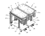
- FIG. 1 is a perspective view showing an example of an embodiment of a gantry unit of the present invention.
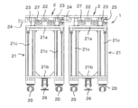
- FIG. 2 is a front view of the stand unit shown in FIG. 1 .
- FIG. 4 is an enlarged front view showing the floating member.
- 13 is an enlarged front view showing a connection guide member and a receiving member in a coupled state.
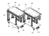
- FIG. FIG. 13 is a perspective view showing the process of connecting two rack modules.
- 1 is a perspective view showing an example of a linear transport module that constitutes the linear transport system of the present invention
- FIG. 7 is a front view of the linear transport module shown in FIG. 6 .
- 7 is an exploded perspective view of a linear transport system constructed using the linear transport module shown in FIG. 6.
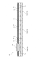
- 1 is a side view showing a linear transport system configured by arranging three linear transport modules in series.
- FIG. FIG. 13 is a perspective view showing how the platform modules are connected to construct a linear transport system.
- FIG. 1 is a perspective view showing an example of an embodiment of a mounting unit to which the present invention is applied.
- This mounting unit 1 can be used by connecting multiple mounting modules 2 in a row, and FIG. 1 shows two mounting modules 2 connected together.
- Each mounting module 2 is provided with a base plate, and by mounting various processing machines, robot arms, etc. on the base plate, it is possible to share either the processing or assembly process for the workpiece.
- the mounting unit 1 can be provided with a linear transport system that passes through the multiple mounting modules 2, and by using this linear transport system, the workpiece to be processed or assembled can be freely transported along the connection direction of the multiple mounting modules 2.
- the gantry unit 1 constitutes a production line that can carry out various types of processing and assembly on a workpiece while transporting the workpiece along the connection direction of the multiple gantry modules 2. Also, by rearranging the arrangement of the multiple gantry modules 2, the order of various types of processing and assembly on the workpiece can be changed as desired, making it easy to rearrange the configuration of the production line.
- the linear transport system that transports the workpiece while passing between the multiple gantry modules 2 will be described later.
- each mounting module 2 constituting the mounting unit 1 comprises a mounting body 21 equipped with casters 20 and capable of moving freely, a base plate 22 arranged above the top plate 21a of the mounting body 21, a plurality of floating members 23 that can freely change the height and inclination of the base plate 22 relative to the top plate 21a, a connection guide member 24 provided at one end of the base plate 22, and a receiving member 25 provided on the base plate 22 on the opposite side to the connection guide member 24.
- the connection guide member 24 and the receiving member 25 form a pair, and two adjacent mounting modules 2 are connected to each other by inserting the connection guide member 24 into a connection slot provided in the receiving member 25.
- the stand body 21 is formed in a generally rectangular shape with the top plate 21a supported by a number of posts 21c on a bottom plate 21b on which the casters 20 are provided.
- the space between the bottom plate 21b and the top plate 21a can be used as a storage space for various processing machines and robot arm controllers and power supplies that are arranged on the base plate 22.
- a foot-operated anti-movement stopper 26 is provided under the bottom plate 21b, and by stepping on the pedal, the fixed legs come into strong contact with the floor surface, allowing the stand body 21 to be fixed on the floor surface.
- each floating member 3 includes a guide rod 30, a lower spherical bearing 31 that connects the guide rod 30 to the top plate 21a in a tiltable manner, an upper spherical bearing 32 that connects the guide rod to the base plate 22 in a tiltable manner, and a compression spring 33 that is provided between the lower spherical bearing 31 and the upper spherical bearing 32 and elastically supports the base plate 22 against the top plate 21a.
- the guide rod 30 is fixed to the lower spherical bearing 31, but slidably mounted to the upper spherical bearing 32.
- the compression spring 33 is compressed in response to the load acting on the base plate 22, and when the base plate 22 descends relative to the gantry body 21, the tip of the guide rod 30 protrudes from the base plate.
- the guide rod 30 and the compression spring 33 are covered by a cylindrical case 34 provided between the top plate 21a and the base plate 22, and this cylindrical case 34 expands and contracts in response to the rise and fall of the base plate 22 relative to the top plate 21a. Therefore, when a load acts on the base plate 22, the attitude of the base plate 22, i.e., the height and inclination, can be freely changed relative to the top plate 21a of the gantry body 21 in response to the load.
- a plurality of locking members 27 are provided adjacent to the floating member 23 between the top plate 21a and the base plate 22 so that the position of the base plate 22 can be temporarily fixed after the position of the base plate 22 has changed.
- Each locking member 27 maintains the base plate 22 at a desired height against the biasing force of the compression spring 33 of the floating member 23, and when the screw plate is tightened, the height of the base plate 22 relative to the top plate 21a decreases according to the amount of rotation. Therefore, if the locking members 27 are adjusted while the base plate 22 is pressed down toward the top plate 21a, the height of the base plate 22 can be temporarily fixed to the height before the load on the base plate 22 is removed, even after the load on the base plate 22 is removed.
- FIG 4 is an enlarged front view showing the state in which the connection guide member 24 and the receiving member 25 are combined.
- the connection guide member 24 is a rod-shaped member that is long and extends along one side of the base plate 22, and its cross section perpendicular to the longitudinal direction is rectangular. This connection guide member 24 is held at a position spaced apart from the side of the base plate 22 by a plurality of support members 24a arranged at a predetermined interval.
- the receiving member 25 is provided on the underside of the base plate 22 at a position opposite the connection guide member 24 across the base plate 22. Therefore, when two rack modules 2A, 2B are placed adjacent to each other, the connection guide member 24 of one rack module 2A and the receiving member 25 of the other rack module 2B are adjacent to each other.
- the receiving member 25 has a connecting slot 25a into which the connecting guide member 24 can be inserted along its longitudinal direction, and when the connecting guide member 24 is accommodated in the connecting slot 25a, it fits tightly into the receiving member 25, so that the two are integrated without rattling.
- the receiving member 25 is provided with a number of guide rollers that come into contact with the connection guide member 24 from four directions, namely, above, below, left and right. These guide rollers are arranged at predetermined intervals along the longitudinal direction of the receiving member 25, and while facilitating the insertion and removal of the connection guide member 24 into the connection slot 25a, they also eliminate any gaps between the connection slot 25a and the connection guide member 25, achieving a tight fit of the connection guide member 24 into the receiving member 25.
- FIG. 5 is a perspective view showing the connection of two adjacent mounting modules 2A, 2B.
- one mounting module 2B is fixed to the floor surface using the movement prevention stoppers 26, and the other mounting module 2A is moved in the X direction relative to the floor surface on the casters 20 to temporarily connect these mounting modules 2A, 2B.
- one mounting module 2A is moved in a direction perpendicular to the connection direction while the connection guide member 24 of that mounting module 2A is inserted into the receiving member 25 of the other mounting module 2B, thereby connecting the base plates 22 of the two mounting modules 2A, 2B to each other.
- connection guide member 24 of one mounting module 2A fits into the receiving member 25 of the other mounting module 2B, and the connection guide member 24, which has a rectangular cross section, is restrained by the guide rollers from the four directions, top, bottom, left, and right, inside the connection slot 25a.
- the floating mechanism 23 provided on each mounting module 2A, 2B causes the height and inclination of the base plate 22 of one mounting module 2A to mimic those of the base plate 22 of the other mounting module 2B, and the base plates 22 of these mounting modules 2A, 2B form a single, smoothly continuous mounting surface.
- the locking members 27 are adjusted to temporarily fix the base plate 22 to the mounting body 21, and then, as shown in FIG. 1, the fixing plate 4 is placed between the two connected base plates 22 and screwed to the base plate 22.
- the base plates 22 of the mounting modules 2A, 2B are integrated together to form a single mounting surface with matching heights and inclinations.
- connection guide member 24, and the receiving member 25 were not present, when connecting two mounting modules 2A and 2B to each other, adjustment work would be required to match the height and inclination of the base plate 22 of one mounting module 2A to the base plate 22 of the other mounting module 2B. Normally, such adjustment work would be performed by individually adjusting the height of the four corners of the base plate 22, which is a very time-consuming task. In contrast, with the mounting unit 1 of this embodiment, it is possible to easily match the height and inclination of the base plates 22 of the mounting modules 2A and 2B by simply connecting two mounting modules 2A and 2B arranged adjacent to each other using the connecting member 24 and the receiving member 25.
- FIGS. 6 and 7 are perspective and front views showing an example of a linear conveying module 10 for constructing the linear conveying system LS of the present invention.
- the linear conveying system is configured by arranging multiple linear conveying modules 10 shown in FIG. 6 in series on the mounting surface of the machine device.
- the linear conveying module 10 includes a module base 11 that is bolted to the mounting surface, a track rail 12 that is fixed to the module base 11, a slider 13 that is attached to the track rail 12, and a carriage 14 that is fixed to the slider 13.
- the track rail 12 and the slider 13 form a linear guide, and the slider 13 is attached to the track rail 12 via a number of rolling elements and has an infinite circulation path for the number of rolling elements. Therefore, the slider 13 can freely reciprocate in the longitudinal direction of the track rail 12, and the carriage 14 that is fixed to the slider 13 can freely move on the module base 11 along the longitudinal direction of the track rail 12.
- the track rail 12 is positioned relative to the module base 11, and when the module base 11 is positioned and fixed to the mounting surface of a machine device, the track rail 12 is positioned relative to the mounting surface, and the carriage 14 can be moved with high precision on the mounting surface.
- any known linear guide can be selected and used depending on the required movement accuracy and load bearing capacity of the carriage 14.
- a thrust force is applied to the carriage 14 by the linear motor 7 along the longitudinal direction of the track rail 12.
- Coil members 7a serving as stators of the linear motor 7 are arranged along the track rail 12 on the module base 11, while magnet members 7b serving as movers of the linear motor 7 are provided on the carriage 14.
- the magnet members 7b are structured such that N poles and S poles are arranged alternately along the movement direction of the carriage 14.
- a linear scale 8a is provided on the carriage 14, while an encoder 8b is provided on the module base 11 at a position opposite the linear scale 8a, such that an output signal according to the amount of movement of the carriage 14 relative to the module base 11 can be obtained from the encoder 8b. Therefore, by controlling the drive signal applied to the linear motor 7 based on the output signal of the encoder 8b, it is possible to arbitrarily control the amount of movement of the carriage 14 on the module base 11.
- the combination of the linear scale 8a and encoder 8b can be any type, such as magnetic or optical.
- linear conveying modules 10 are arranged in series along the longitudinal direction of the track rail 12, and are used with the end faces of adjacent linear conveying modules 10 butted against each other.
- FIG. 9 is a side view showing a linear transport system LS configured by arranging three linear transport modules 10A, 10B, and 10C in series along the longitudinal direction of the track rail 12.
- the carriage 14 and the slider 13 are provided only on one linear module 10A among the three linear modules 10A, 10B, and 10C, and the slider 13 can reciprocate over the entire length of the linear transport system LS while moving between the track rails 12 arranged on each linear module 10A, 10B, and 10C.
- FIG. 9 shows an example in which three linear modules 10A, 10B, and 10C are arranged in series, the number of linear modules to be arranged can be determined arbitrarily depending on the scale of the required linear transport system.
- each linear transport module 10 the total length of the track rail 12 is set slightly shorter than the total length of the module base 11, and a part of the rail mounting surface 15 is exposed at both ends of the module base 11. Therefore, when two linear transport modules 10 are arranged in series and fixed to the mounting surface of a machine device, the end of the track rail 12 of one linear transport module 10 and the end of the track rail 12 of the other linear transport module 10 are separated by a gap.
- a connecting rail 9 is arranged at the boundary between the linear transport module 10A and the linear transport module 10B and the boundary between the linear transport module 10B and the linear transport module 10C, and the connecting rail 9 is fixed to the rail mounting surface 15 of each linear transport module 10 so as to straddle the two adjacent linear transport modules 10.
- the track rail 12 of the three linear transport modules 10A, 10B, and 10C arranged in series is configured as a single guide track.
- a linear transport system LS formed by multiple linear transport modules 10 can also include multiple carriages 14, in which case each carriage 14 can be given an individual motion independent of the other carriages 14.
- Figure 10 is a perspective view showing how the multiple mount modules 2 described above are connected to form a mount unit 1, and a linear transport system LS is constructed on the mount unit 1.
- the linear transport modules 10A, 10B are fixed to the base plate 22 of each mount module 2A, 2B so that they are positioned in the same straight line.
- a predetermined gap is created between the linear transport module 10A fixed to the base plate 22 of one mount module 2A and the linear transport module 10B fixed to the base plate 22 of the other mount module 2B, and this gap is, for example, the width of one of the linear transport modules.
- the linear transport module 10C is inserted between the linear transport modules 10A and 10B so as to straddle the boundary between these frame modules, and the linear transport module 10C is fixed to each base plate 22, so that the three linear transport modules 10A, 10B, and 10C are aligned in series.
- the connecting rails 9 are fixed so as to straddle the adjacent linear transport modules 10, and the track rails 12 included in each linear transport module 10 form a single guide track including the connecting rails 9.
- the carriage 14 fixed to the slider 13 is propelled by the linear motor 7 and can reciprocate over the two base modules 2A and 2B.
- a linear transport system LS capable of transporting workpieces over multiple base modules 2 can be constructed.
- the heights and inclinations of two adjacent base plates 22 can be easily matched simply by connecting two mounting modules 2A, 2B arranged adjacent to each other using the connecting member 24 and the receiving member 25, and a linear transport system LS can be easily constructed that can freely transport objects such as workpieces between one mounting module 2 and another mounting module 2.
Landscapes
- Engineering & Computer Science (AREA)
- Mechanical Engineering (AREA)
- Non-Mechanical Conveyors (AREA)
- Multi-Process Working Machines And Systems (AREA)
- Automatic Assembly (AREA)
Abstract
Dans la présente invention, chaque module de support (2) comprend : un corps de support (21) ; une plaque de base (22) servant de surface de montage d'un dispositif de machine ; un élément flottant (23) disposé entre la plaque de base (22) et une plaque supérieure (21a) du corps de support (21) et capable de modifier librement une hauteur et une inclinaison de la plaque de base (22) par rapport à la plaque supérieure (21a) ; un élément de guidage de raccordement (24) disposé au niveau d'une extrémité latérale de la plaque de base (22) ; et un élément de réception (25) disposé au niveau de l'extrémité latérale de la plaque de base (22) sur un côté opposé à l'élément de guidage de raccordement (24). L'élément de guidage de raccordement (24) de l'un des modules de support (2) disposés de manière adjacente et l'élément de réception (25) de l'autre des modules de support (2) sont ajustés l'un à l'autre pour constituer une surface de montage dans laquelle les plaques de base (22) de ces modules de support (2) sont continues les unes avec les autres.
Applications Claiming Priority (2)
| Application Number | Priority Date | Filing Date | Title |
|---|---|---|---|
| JP2023095305A JP2024176611A (ja) | 2023-06-09 | 2023-06-09 | 架台ユニット及びリニア搬送システム |
| JP2023-095305 | 2023-06-09 |
Publications (1)
| Publication Number | Publication Date |
|---|---|
| WO2024252837A1 true WO2024252837A1 (fr) | 2024-12-12 |
Family
ID=93795415
Family Applications (1)
| Application Number | Title | Priority Date | Filing Date |
|---|---|---|---|
| PCT/JP2024/017135 Ceased WO2024252837A1 (fr) | 2023-06-09 | 2024-05-08 | Unité de support et système de transport linéaire |
Country Status (3)
| Country | Link |
|---|---|
| JP (1) | JP2024176611A (fr) |
| TW (1) | TW202500309A (fr) |
| WO (1) | WO2024252837A1 (fr) |
Citations (7)
| Publication number | Priority date | Publication date | Assignee | Title |
|---|---|---|---|---|
| JPH037314A (ja) * | 1989-06-05 | 1991-01-14 | Minolta Camera Co Ltd | 射出成形装置 |
| JP2003062739A (ja) * | 2001-08-28 | 2003-03-05 | Ibiden Co Ltd | 生産ラインシステム、生産ラインシステムの制御方法、ワーク処理システム |
| JP2008023637A (ja) * | 2006-07-19 | 2008-02-07 | Yokogawa Electric Corp | 移送システム |
| JP2008254093A (ja) * | 2007-04-03 | 2008-10-23 | Jtekt Corp | 加圧治具集約設備 |
| JP2011083113A (ja) * | 2009-10-07 | 2011-04-21 | Thk Co Ltd | リニアモータアクチュエータ |
| JP2011224742A (ja) * | 2010-04-21 | 2011-11-10 | Canon Inc | ロボットセル |
| JP2020075334A (ja) * | 2018-11-08 | 2020-05-21 | 株式会社Fdkエンジニアリング | 架台、および架台の設置方法 |
-
2023
- 2023-06-09 JP JP2023095305A patent/JP2024176611A/ja active Pending
-
2024
- 2024-05-08 WO PCT/JP2024/017135 patent/WO2024252837A1/fr not_active Ceased
- 2024-05-20 TW TW113118503A patent/TW202500309A/zh unknown
Patent Citations (7)
| Publication number | Priority date | Publication date | Assignee | Title |
|---|---|---|---|---|
| JPH037314A (ja) * | 1989-06-05 | 1991-01-14 | Minolta Camera Co Ltd | 射出成形装置 |
| JP2003062739A (ja) * | 2001-08-28 | 2003-03-05 | Ibiden Co Ltd | 生産ラインシステム、生産ラインシステムの制御方法、ワーク処理システム |
| JP2008023637A (ja) * | 2006-07-19 | 2008-02-07 | Yokogawa Electric Corp | 移送システム |
| JP2008254093A (ja) * | 2007-04-03 | 2008-10-23 | Jtekt Corp | 加圧治具集約設備 |
| JP2011083113A (ja) * | 2009-10-07 | 2011-04-21 | Thk Co Ltd | リニアモータアクチュエータ |
| JP2011224742A (ja) * | 2010-04-21 | 2011-11-10 | Canon Inc | ロボットセル |
| JP2020075334A (ja) * | 2018-11-08 | 2020-05-21 | 株式会社Fdkエンジニアリング | 架台、および架台の設置方法 |
Also Published As
| Publication number | Publication date |
|---|---|
| TW202500309A (zh) | 2025-01-01 |
| JP2024176611A (ja) | 2024-12-19 |
Similar Documents
| Publication | Publication Date | Title |
|---|---|---|
| US11718488B2 (en) | Linear motor conveyor system with diverter and method for design and configuration thereof | |
| US6099217A (en) | Device for spatially moving a body with three to six degrees of freedom in a controlled manner | |
| US5903125A (en) | Positioning system | |
| US7845257B2 (en) | Ultra-precision machine tool | |
| US8109395B2 (en) | Gantry positioning system | |
| US6327929B1 (en) | Two dimensional drive system | |
| US6495935B1 (en) | Linear motor drive unit | |
| JP5722865B2 (ja) | 工作機械用ガイドキャリッジ・アセンブリ | |
| US7234675B2 (en) | Vertical guide unit and stage system with the same unit | |
| WO2018055709A1 (fr) | Dispositif de transporteur linéaire | |
| JP2001343058A (ja) | 幅広構造の駆動装置 | |
| JP7292819B2 (ja) | コンベアテーブル移載装置、搬送システムおよびコンベアテーブル移載方法 | |
| JPH07124831A (ja) | リニアガイド装置 | |
| US4676492A (en) | Shallow X-Y table positioning device having large travel capability | |
| WO2024252837A1 (fr) | Unité de support et système de transport linéaire | |
| WO2000000323A1 (fr) | Bati pour machine-outil | |
| CN222254704U (zh) | 组合式直线轨道装置 | |
| CN117145861A (zh) | 组合式直线轨道装置及其组合方法 | |
| JP2024176662A (ja) | リニア搬送システム | |
| JP7614445B2 (ja) | コンベアテーブル搬送システムおよびコンベアテーブル搬送方法 | |
| JPH0680529U (ja) | 駆動装置及びこれを具備したxy駆動装置 | |
| CN120858236A (zh) | 输送模块、间隔件及程序 | |
| JPH11280761A (ja) | 直動転がり案内ユニット及びそれを用いたxyテーブル装置 | |
| US20250282564A1 (en) | Transport system | |
| JP2883628B2 (ja) | X―yテーブル装置 |
Legal Events
| Date | Code | Title | Description |
|---|---|---|---|
| 121 | Ep: the epo has been informed by wipo that ep was designated in this application |
Ref document number: 24819074 Country of ref document: EP Kind code of ref document: A1 |
|
| NENP | Non-entry into the national phase |
Ref country code: DE |